Embed Size (px)
Citation preview

ENGG1100 Ch6: Introduction To Engineering Design (Digital
Logic)
Part 2 of digital logic KH WONG
ENGG1100. Ch6-Digital Logic (part2) v3h 1
Part 2
• Implementations of logic functions in programs– Method1: Logic Formula (use of IF-Then-Else)– Method2: Truth table (Use of Switch-case) – Examples– **For both methods, you don’t need to write the
full programs, you only need to understand and modify the examples given.
• Video link http://www.youtube.com/channel/UCjlkiXFReY2Ubv6WX8m4F8A?feature=watch
ENGG1100. Ch6-Digital Logic (part2) v3h 2

Method 1: to implement logic operations in a program using
Logic Formula (use of IF-Then-Else)
ENGG1100. Ch6-Digital Logic (part2) v3h 3

Sensors of our robot
• Sensors– S1,S2,S3 each can be ‘1’ or ‘0’– Magnetic field detected =>Si=0– No Magnetic field detected =>Si=1
ENGG1100. Ch6-Digital Logic (part2) v3h
44
S2 S3 S1
The robot is facing you
Motors of our robot
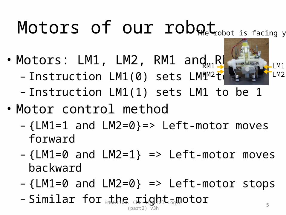
• Motors: LM1, LM2, RM1 and RM2– Instruction LM1(0) sets LM1 to be 0– Instruction LM1(1) sets LM1 to be 1
• Motor control method– {LM1=1 and LM2=0}=> Left-motor moves forward – {LM1=0 and LM2=1} => Left-motor moves backward – {LM1=0 and LM2=0} => Left-motor stops– Similar for the right-motor
ENGG1100. Ch6-Digital Logic (part2) v3h 55
RM1RM2
LM1LM2
The robot is facing you

In the lab : use switches to simulate sensors;use LEDs to simulate motors
• Testing hardware setup in our robot system• LM1 is an output for a Light Emitting Diode LED
– When LM1=1 it is on– When LM1=0 it is off– Same for LM2,RM1 and RM2 etc
• S1 is a switch– When depressed S1=0– When released S1=1– Same for S2,S3 and S4
ENGG1100. Ch6-Digital Logic (part2) v3h 6Simulate sensors S1,S2 etc
Simulate MotorsLM1,LM2RM1,EM2
Programing procedures
• Details in the document– “Document B: A tutorial of how to use the controller board”, of
Engg1100 Lab manual 5 from elearninghttps://elearn.cuhk.edu.hk/webapps/login/
• Edit program• Compile• Download to the SMART-car-board• Run the program• Demo video in http://
www.youtube.com/channel/UCjlkiXFReY2Ubv6WX8m4F8A?feature=watch
ENGG1100. Ch6-Digital Logic (part2) v3h 7
Method 1 (Use of If-then-else): This program will enable the robot to follow the magnetic path
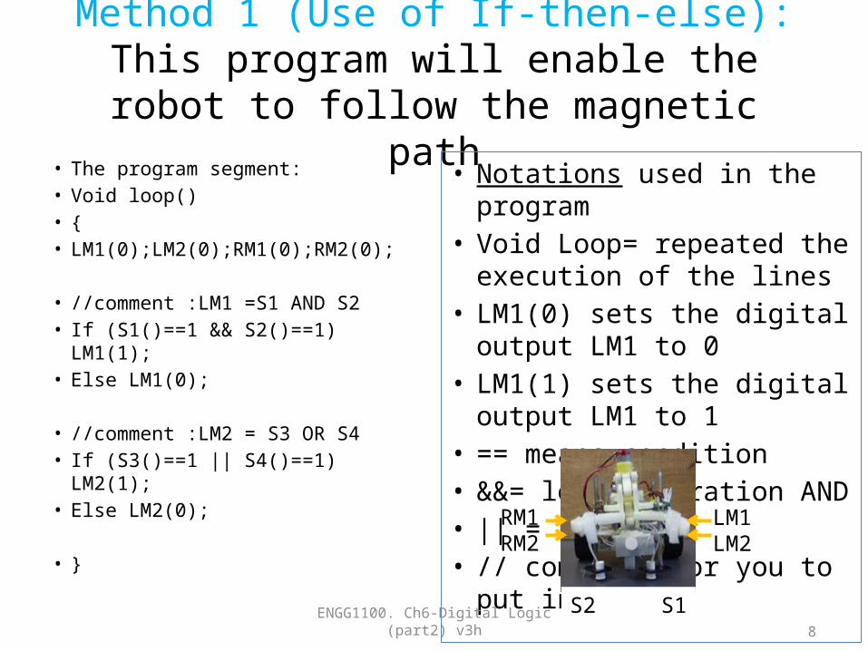
• The program segment:• Void loop()• {• LM1(0);LM2(0);RM1(0);RM2(0);
• //comment :LM1 =S1 AND S2• If (S1()==1 && S2()==1) LM1(1);• Else LM1(0);
• //comment :LM2 = S3 OR S4• If (S3()==1 || S4()==1) LM2(1);• Else LM2(0);
• }
• Notations used in the program• Void Loop= repeated the
execution of the lines• LM1(0) sets the digital output
LM1 to 0• LM1(1) sets the digital output
LM1 to 1• == means condition• &&= logic operation AND• || = Logic OR• // comment, for you to put in
notesENGG1100. Ch6-Digital Logic (part2) v3h
8
S2 S1
RM1RM2
LM1LM2
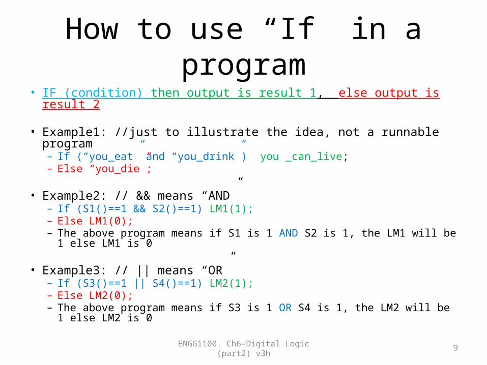
How to use “If” in a program• IF (condition) then output is result 1, else output is result 2
• Example1: //just to illustrate the idea, not a runnable program– If (“you_eat” and “you_drink”) you _can_live;– Else “you_die”;
• Example2: // && means “AND”– If (S1()==1 && S2()==1) LM1(1);– Else LM1(0);– The above program means if S1 is 1 AND S2 is 1, the LM1 will be 1 else LM1 is 0
• Example3: // || means “OR”– If (S3()==1 || S4()==1) LM2(1);– Else LM2(0);– The above program means if S3 is 1 OR S4 is 1, the LM2 will be 1 else LM2 is 0
ENGG1100. Ch6-Digital Logic (part2) v3h 9
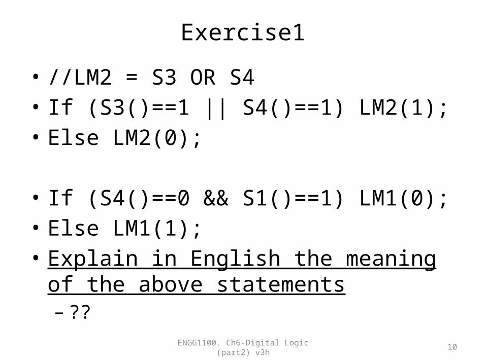
Exercise1
• //LM2 = S3 OR S4• If (S3()==1 || S4()==1) LM2(1);• Else LM2(0);
• If (S4()==0 && S1()==1) LM1(0);• Else LM1(1);• Explain in English the meaning of the above
statements– ??
ENGG1100. Ch6-Digital Logic (part2) v3h 10
Method 2 : to implement logic operation in a program using
truth table (Use of Switch-Case)
ENGG1100. Ch6-Digital Logic (part2) v3h 11
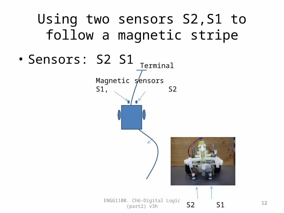
Using two sensors S2,S1 to follow a magnetic stripe
• Sensors: S2 S1
ENGG1100. Ch6-Digital Logic (part2) v3h 12
Magnetic sensorsS1, S2
Terminal
12S2 S1

Robot specifications of the sensor input and motor outputs
• Inputs:– S1 S2 are magnetic sensors
• S1 =‘1’ if it detects no magnetic material• S1 =‘0’ if it detects magnetic material
• Outputs for left motor (similar to right motor) :– LM1, LM2=“10” left motor moves forward– LM1, LM2=“01” left motor moves backward– LM1, LM2=“00” or “11” left motor stops
ENGG1100. Ch6-Digital Logic (part2) v3h 13
Magnetic sensorsS1, S2
Magnetic stripe
Robot car
Terminal

Motor control
• Motor control outputs for both motors– Robot forward: LM1, LM2, RM1, RM2=“1010”– Robot turns right: LM1, LM2, RM1, RM2=“1000”– Robot turns left: LM1, LM2, RM1, RM2=“0010”
ENGG1100. Ch6-Digital Logic (part2) v3h 14
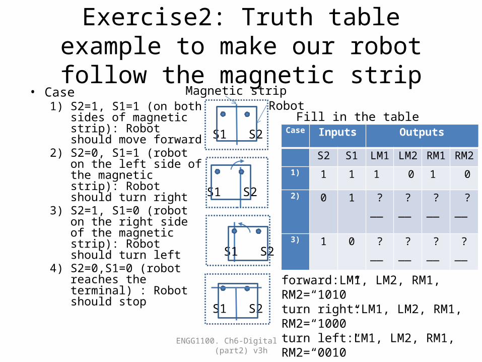
Exercise2: Truth table example to make our robot follow the magnetic strip
• Case1) S2=1, S1=1 (on both
sides of magnetic strip): Robot should move forward
2) S2=0, S1=1 (robot on the left side of the magnetic strip): Robot should turn right
3) S2=1, S1=0 (robot on the right side of the magnetic strip): Robot should turn left
4) S2=0,S1=0 (robot reaches the terminal) : Robot should stop
ENGG1100. Ch6-Digital Logic (part2) v3h 15
Case Inputs Outputs
S2 S1 LM1 LM2 RM1 RM2
1) 1 1 1 0 1 0
2) 0 1 ?__ ?__ ?__ ?__
3) 1 0 ?__ ?__ ?__ ?__
4) 0 0 ?__
?__
?__
?__
Magnetic strip
S1 S2
S1 S2
S1 S2
forward:LM1, LM2, RM1, RM2=“1010”turn right:LM1, LM2, RM1, RM2=“1000”turn left:LM1, LM2, RM1, RM2=“0010”S1 S2
Fill in the tableRobot
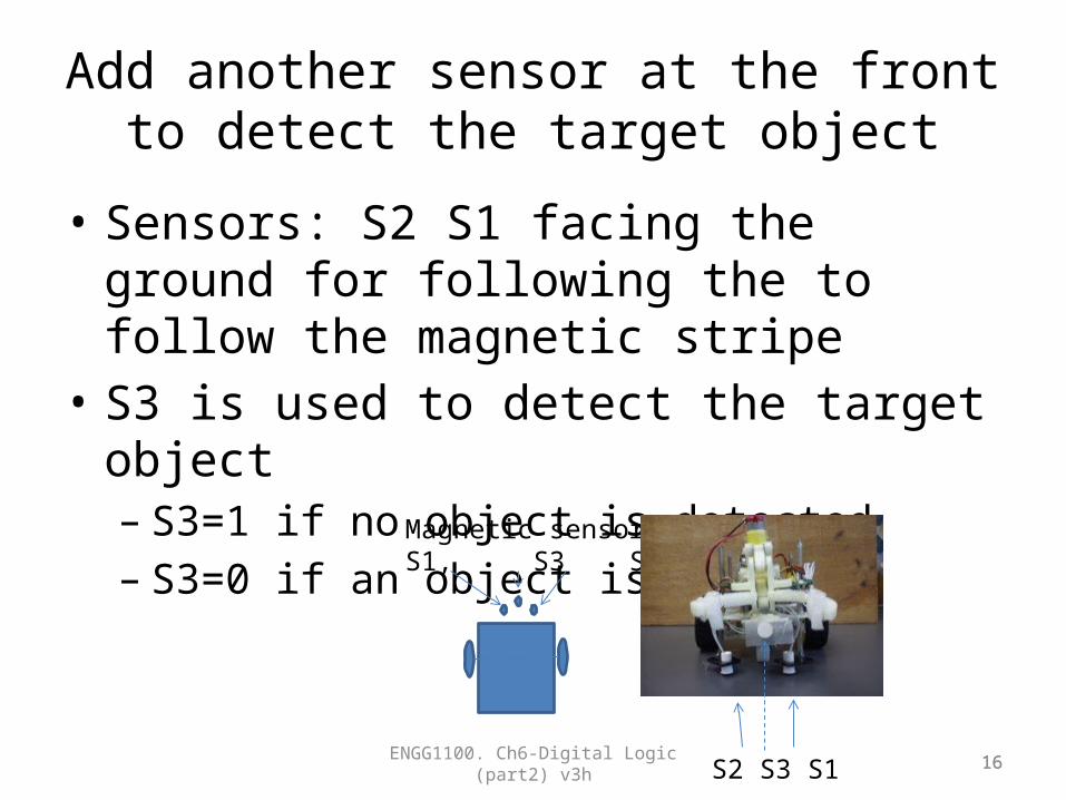
Add another sensor at the front to detect the target object
• Sensors: S2 S1 facing the ground for following the to follow the magnetic stripe
• S3 is used to detect the target object– S3=1 if no object is detected– S3=0 if an object is detected
ENGG1100. Ch6-Digital Logic (part2) v3h 16
Magnetic sensorsS1, S3 S2
16S2 S3 S1
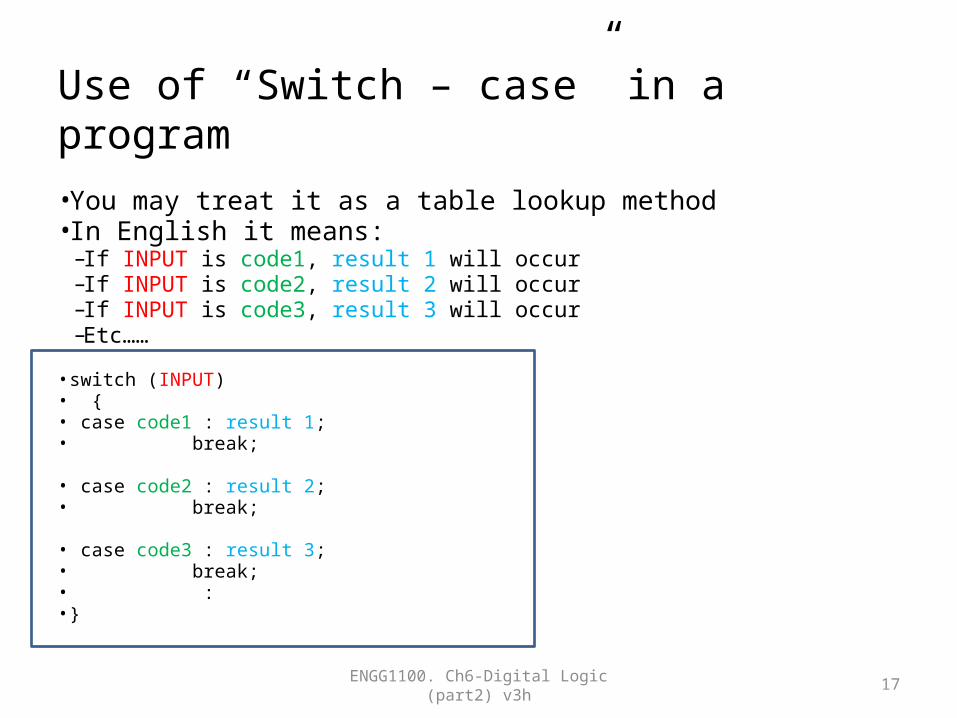
Use of “Switch – case” in a program
• You may treat it as a table lookup method• In English it means:
– If INPUT is code1, result 1 will occur– If INPUT is code2, result 2 will occur– If INPUT is code3, result 3 will occur– Etc……
• switch (INPUT) • {• case code1 : result 1;• break;
• case code2 : result 2;• break;
• case code3 : result 3;• break;• :• }
ENGG1100. Ch6-Digital Logic (part2) v3h 17
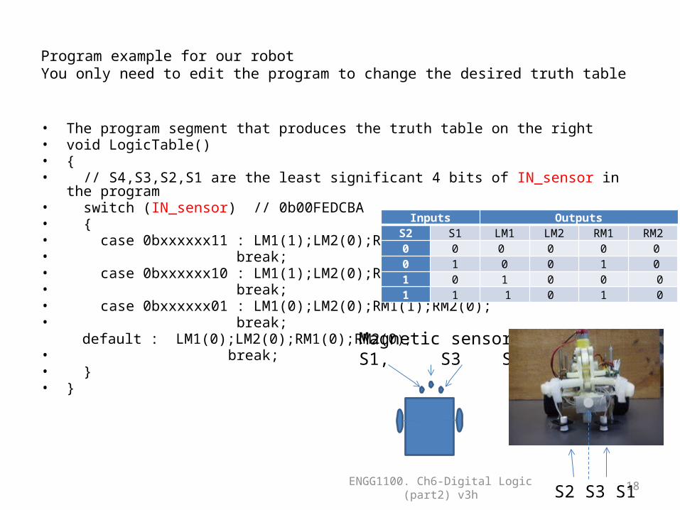
Program example for our robotYou only need to edit the program to change the desired truth table
• The program segment that produces the truth table on the right• void LogicTable()• {• // S4,S3,S2,S1 are the least significant 4 bits of IN_sensor in the program• switch (IN_sensor) // 0b00FEDCBA• {• case 0bxxxxxx11 : LM1(1);LM2(0);RM1(1);RM2(0);• break;• case 0bxxxxxx10 : LM1(1);LM2(0);RM1(0);RM2(0);• break;• case 0bxxxxxx01 : LM1(0);LM2(0);RM1(1);RM2(0);• break;
default : LM1(0);LM2(0);RM1(0);RM2(0);• break;• } • }
ENGG1100. Ch6-Digital Logic (part2) v3h 18
Inputs OutputsS2 S1 LM1 LM2 RM1 RM20 0 0 0 0 00 1 0 0 1 01 0 1 0 0 0 1 1 1 0 1 0
Magnetic sensorsS1, S3 S2
S2 S3 S1
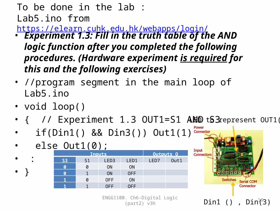
To be done in the lab : Lab5.ino from https://elearn.cuhk.edu.hk/webapps/login/
• Experiment 1.3: Fill in the truth table of the AND logic function after you completed the following procedures. (Hardware experiment is required for this and the following exercises)
• //program segment in the main loop of Lab5.ino• void loop()• { // Experiment 1.3 OUT1=S1 AND S3• if(Din1() && Din3()) Out1(1);• else Out1(0);• :• }
ENGG1100. Ch6-Digital Logic (part2) v3h 19Din1 () , Din(3)
LED to represent OUT1()
Inputs Outputs QS3 S1 LED3 LED1 LED7 Out10 0 ON ON 0 1 ON OFF 1 0 OFF ON 1 1 OFF OFF

Appendix1:Answer for the exercise1
• //LM2 = S3 OR S4• If (S3()==1 || S4()==1) LM2(1);• Else LM2(0);
• If (S4()==0 && S1()==1) LM1(0);• Else LM1(1);• Explain in English the meaning of the above
statements– ?? ans: if S3 is 1 OR S4 is 1 LM2 is 1, else LM2 is 0– ans: if S4 is 0 AND S1 is 1 LM1 is 0, else LM2 is 1
ENGG1100. Ch6-Digital Logic (part2) v3h 20
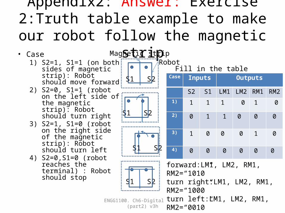
Appendix2: Answer: Exercise 2:Truth table example to make our robot follow the
magnetic strip• Case
1) S2=1, S1=1 (on both sides of magnetic strip): Robot should move forward
2) S2=0, S1=1 (robot on the left side of the magnetic strip): Robot should turn right
3) S2=1, S1=0 (robot on the right side of the magnetic strip): Robot should turn left
4) S2=0,S1=0 (robot reaches the terminal) : Robot should stop
ENGG1100. Ch6-Digital Logic (part2) v3h 21
Case Inputs Outputs
S2 S1 LM1 LM2 RM1 RM2
1) 1 1 1 0 1 0
2) 0 1 1 0 0 0
3) 1 0 0 0 1 0
4) 0 0 0
0
0
0
Magnetic strip
S1 S2
S1 S2
S1 S2
forward:LM1, LM2, RM1, RM2=“1010”turn right:LM1, LM2, RM1, RM2=“1000”turn left:LM1, LM2, RM1, RM2=“0010”S1 S2
Fill in the tableRobot

Appendix 3: ReferenceMain loop of experiment5(lab5.ino)
from https://elearn.cuhk.edu.hk/webapps/login/• void loop()• {• // Experiment 1.3 OUT1=S1 AND S3• if(Din1() && Din3()) Out1(1);• else Out1(0);
• // Experiment 1.4 OUT3=S1 OR S3• if(Din1() || Din3()) Out3(1);• else Out3(0);• • // Experiment 2.1 OUT2=(S2 AND S3) AND S4• if((Din2() && Din3()) && Din4()) Out2(1);• else Out2(0);• • // Experiment 2.2 OUT4=(S2 AND S3) OR S4• if((Din2() && Din3()) || Din4()) Out4(1);• else Out4(0);
• }
ENGG1100. Ch6-Digital Logic (part2) v3h 22
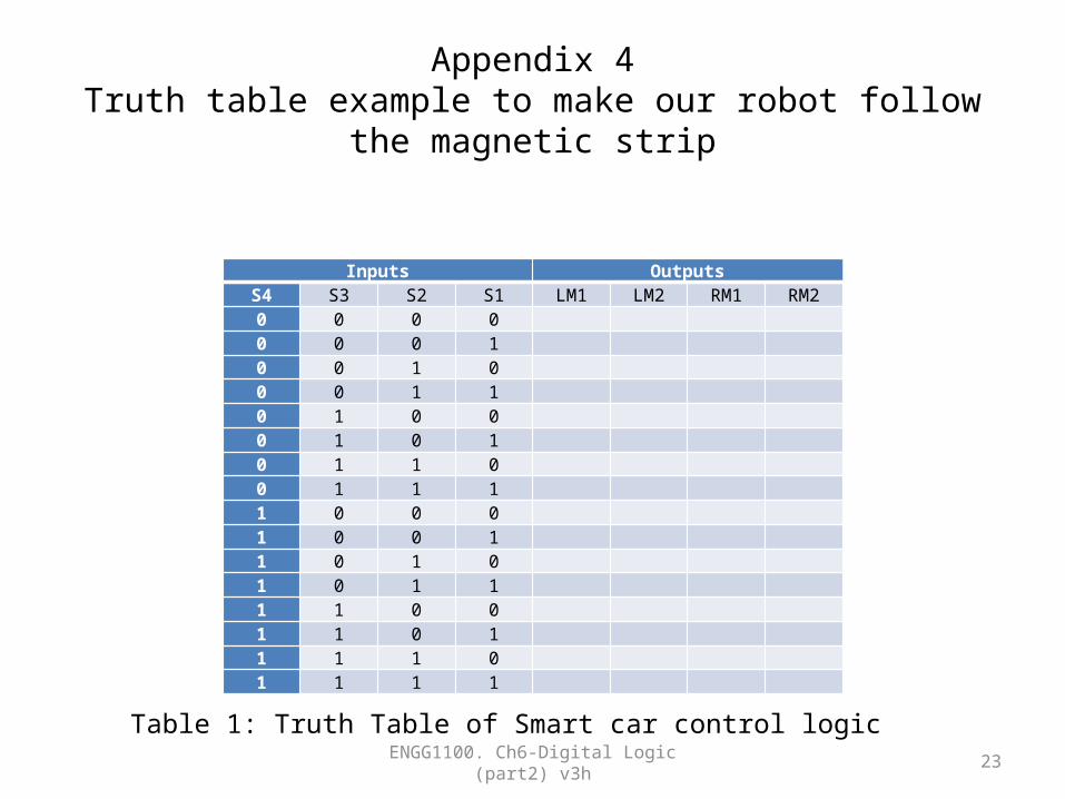
Appendix 4Truth table example to make our robot follow the magnetic strip
Inputs OutputsS4 S3 S2 S1 LM1 LM2 RM1 RM20 0 0 0 0 0 0 1 0 0 1 0 0 0 1 1 0 1 0 0 0 1 0 1 0 1 1 0 0 1 1 1 1 0 0 0 1 0 0 1 1 0 1 0 1 0 1 1 1 1 0 0 1 1 0 1 1 1 1 0 1 1 1 1
Table 1: Truth Table of Smart car control logicENGG1100. Ch6-Digital Logic (part2) v3h 23