Embed Size (px)
Citation preview
vertigineENG
OWNER’S MANUAL

Thank you for choosing a DEDAcciAi product. We in DEDAcciAi develop, manufacture, and constantly test our products in order to maintain the highest standards of quality.We ask for your collaboration to preserve and correctly use DEDAcciAi components.To achieve this, we invite you to read these instructions carefully and retain this manual for future use. if you sell your DEDAcciAi frame or components to someone else, please include this manual.
en
g
CONTENETS CONTENTS
inDEx ____________________________________________________________________ pag. 6
USE LiMiTS ________________________________________________________________ pag. 6
WHAT iS iMPORTAnT FOR YOUR SAFETY? _____________________________________ pag. 7
THE VERTIGINE FRAME KiT __________________________________________________ pag. 8
PARTS AnD ASSEMBLinG ____________________________________________________ pag. 11
eng

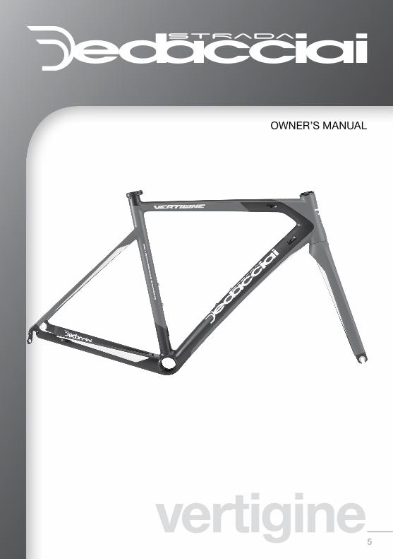
5vertigine
OWNER’S MANUAL
6
en
gINdEx
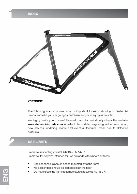
VERTIGINE
The following manual shows what is important to know about your Dedacciai Strada frame kit you are going to purchase and/or to equip as bicycle
We highly invite you to carefully read it and to periodically check the website www.dedacciaistrada.com in order to be updated regarding further information, new advices, updating review and eventual technical recall due to defective products.
USE LIMITS
Frame set respecting rules ISO 4210 – EN 14781Frame set for bicycles intended for use on roads with smooth surfaces
• Bags or panniers should not be mounted onto the frame• No passengers should be carried except the rider• Do not expose the frame to temperatures above 65 °C (150 F)
7
We highly suggest to equip your Dedacciai Strada frame kit to professional and qualified mechanic official Dedacciai.
Every year, or every 5.000 km, inspect and check-up the frame for the grease operation service, in that occasion it is important to check carefully the frame with particular regards to the connection between head tube and down tube, down tube to bottom bracket. Also inspect carefully the front fork with particular regards to the steering tube.
Before every ride, it is recommended that the entire bicycle is checked, with particular attention to the frame, in order to detect any possible cracks. Suspected cracks should be checked with your local dealer. The areas that require particular attention are the down tube-head tube joint and the seat tube-bottom bracket casing. Furthermore take care of the following listed points:
• Inspect that the fork rotates freely with the common headset tolerance. Check the stem to be correctly tightened to the steering tube.
• Check that the handlebar is tightened to the stem at the suggested Nm.
• Inspect the plate fixing bolts of the stem by checking the correct position and the integrity. Also check that the plate does not show any cracks or abrasions.
• Check the tightening bolts of the stem on the steering tube by checking that they are in the right position, the filets must not have no cracks or abrasions.
• Check the saddle stability on the seat post. If appears irregular movements, before tightening definetly, check further saddle and seat post in order to verify the components integrity.
• Ensure that the seat post is not able to rotate in the seat tube and it dont flex in the frame. If occurred, before tightening the seat clamp, disassemble the seat post and inspect it in order to verify its integrity.
AfTER A fALL OR AN ACCIdENT IT IS REqUIREd TO ChECk dEEpLy ALL ThE bICyCLE ANd fRAME!
We remind you that composite materials can suffer damage and can de-laminate in hidden areas after an impact or shock. They can break without warning. Both unusual noises and abnormal handling are signs of potential danger! These should not be underestimated. A qualified technician should check the bicycle!
WhAT IS IMpORTANT fOR yOUR SAfETy?
8
en
g
VERTIGINE is the fast and performing frame kit only suitable for road purpose on smooth asphalt.
VERTIGINE has been developed for all cycling enthusiasts which are looking for the quality/value combination. It weight less than one kg in order to allow superior components/groupset equipment.
The frame kit is suitable for both the electronic and mechanical devices through the light alloy cable stopper which are included in the kit. For the electronic shifting it is suggested to put the battery inside the seat post.
Each VERTIGINE frame carries a serial number, stamped underneath of the down tube, close to the bottom bracket. The serial number is used for traceability and warrantee purposes. Do not remove or grind the number.
4.1 MATERIAL
Toray Carbon layer as here described:
• TORAY 50T front monocoque
• TORAY 40T rear triangle
• Full Carbon bottom bracket
• Carbon drop out (rear drop-out with reinforced alloy body)
• Alloy front derailleur hanger
• Alloy rear derailleur hanger
4.2 WEIGhT
• 980 grams for M size in painted conditions
• F-24 fork of 365 grams in painted conditions
*Weight of painted frame, real weight may differ from the weight mentioned above by ± 7%
ThE VERTIGINE fRAME kIT
9
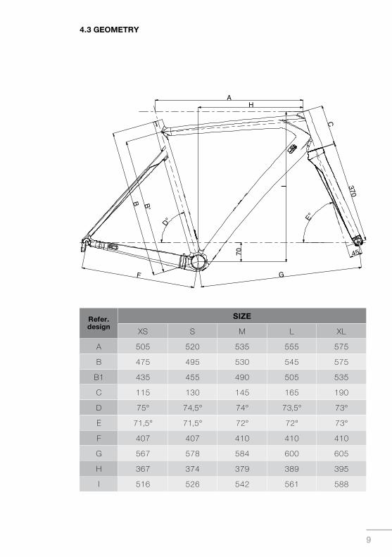
4.3 GEOMETRy
Refer.design
SIZE
xS S M L xL
A 505 520 535 555 575
B 475 495 530 545 575
B1 435 455 490 505 535
c 115 130 145 165 190
D 75° 74,5° 74° 73,5° 73°
E 71,5° 71,5° 72° 72° 73°
F 407 407 410 410 410
G 567 578 584 600 605
H 367 374 379 389 395
i 516 526 542 561 588
10
en
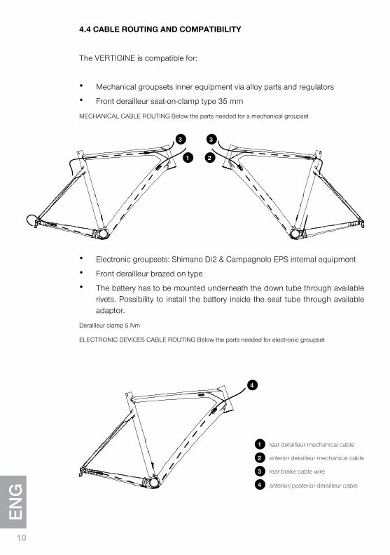
g4.4 CAbLE ROUTING ANd COMpATIbILITy
The VERTIGINE is compatible for:
• Mechanical groupsets inner equipment via alloy parts and regulators
• Front derailleur seat-on-clamp type 35 mm
MECHANICAL CABLE ROUTING Below the parts needed for a mechanical groupset
• Electronic groupsets: Shimano Di2 & Campagnolo EPS internal equipment
• Front derailleur brazed on type
• The battery has to be mounted underneath the down tube through available rivets. Possibility to install the battery inside the seat tube through available adaptor.
Derailleur clamp 5 Nm
ELECTRONIC DEVICES CABLE ROUTING Below the parts needed for electronic groupset
3
1
2
4
rear brake cable wire
anterior/posterior derailleur cable
rear derailleur mechanical cable
anterior derailleur mechanical cable
4
3 3
1 2
11
5.1 fORk
F-24 monocoque carbon tapered steering tube with the following features:
• carbon blades• carbon drop out • Finishing: External lamination UD• Steerer: 1”1/8 top 1”1/2 bottom, • Steerer tube length 330 mm• Rake 45 mm• Recommended compression plug: Dedacciai 23,5 mm part code n°EXP• Weight 365 grams
5.2 hEAdSET
45° Semi oversized angular contact bearing part code n° SSDIFF84.
• Upper bearing: 1 1/8” MSS118R• Lower bearing: 1 1/2” MSS112118R
pARTS ANd ASSEMbLING
12
en
g
20
en
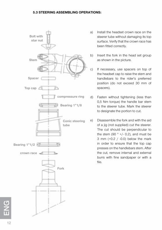
g5.3 STEERING ASSEMbLING OPERATIONS:
a) Install the headset crown race on the steerer tube without damaging its top surface. Verify that the crown race has been fitted correctly.
b) Insert the fork in the head set group
as shown in the picture. c) If necessary, use spacers on top of
the headset cap to raise the stem and handlebars to the rider’s preferred position (do not exceed 30 mm of spacers).
d) Fasten without tightening (less than
0,5 Nm torque) the handle bar stem to the steerer tube. Mark the steerer to designate the portion to cut.
e) Disassemble the fork and with the aid
of a jig (not supplied) cut the steerer. The cut should be perpendicular to the stem (90 ° +/- 0.2), and must be 3 mm (+0.2 / -0.0) below the mark in order to ensure that the top cap presses on the handlebars stem. After the cut, remove internal and external burrs with fine sandpaper or with a file.
bolt with star nut
Stem
Spacer
Top cap
bearing 1”1/8
bearing 1”1/2
crown race
Conic steering tube
Fork
compressure ring
1321
WARNING: the carbon dust and resin generated during cutting and sanding is harmful. Do not inhale it!
WARNING: wear gloves, glasses and mask during cutting operation, as the fibers released can be harmful and cause allergies.
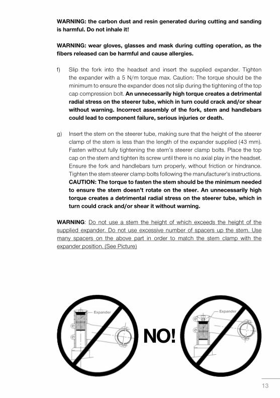
f) Slip the fork into the headset and insert the supplied expander. Tighten the expander with a 5 N/m torque max. caution: The torque should be the minimum to ensure the expander does not slip during the tightening of the top cap compression bolt. An unnecessarily high torque creates a detrimental radial stress on the steerer tube, which in turn could crack and/or shear without warning. Incorrect assembly of the fork, stem and handlebars could lead to component failure, serious injuries or death.
g) Insert the stem on the steerer tube, making sure that the height of the steerer
clamp of the stem is less than the length of the expander supplied (43 mm). Fasten without fully tightening the stem’s steerer clamp bolts. Place the top cap on the stem and tighten its screw until there is no axial play in the headset. Ensure the fork and handlebars turn properly, without friction or hindrance. Tighten the stem steerer clamp bolts following the manufacturer’s instructions. CAUTION: The torque to fasten the stem should be the minimum needed to ensure the stem doesn’t rotate on the steer. An unnecessarily high torque creates a detrimental radial stress on the steerer tube, which in turn could crack and/or shear it without warning.
WARNING: Do not use a stem the height of which exceeds the height of the supplied expander. Do not use excessive number of spacers up the stem. Use many spacers on the above part in order to match the stem clamp with the expander position. (See Picture)
Expander Expander
NO!
14
en
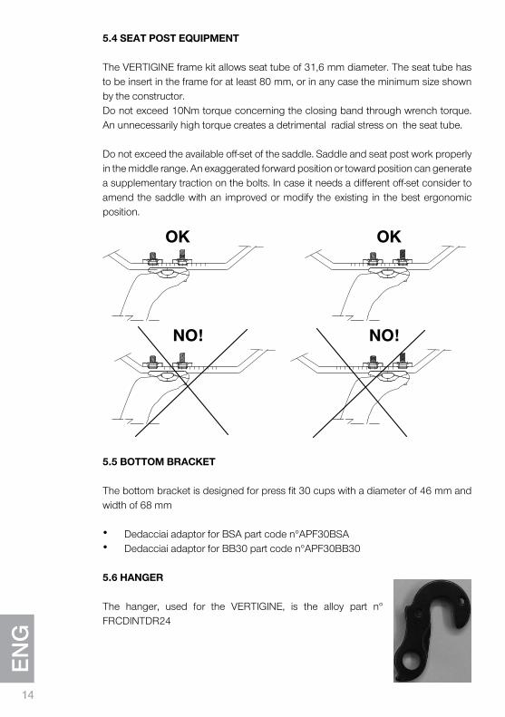
g5.4 SEAT pOST EqUIpMENT
The VERTIGINE frame kit allows seat tube of 31,6 mm diameter. The seat tube has to be insert in the frame for at least 80 mm, or in any case the minimum size shown by the constructor. Do not exceed 10Nm torque concerning the closing band through wrench torque. An unnecessarily high torque creates a detrimental radial stress on the seat tube.
Do not exceed the available off-set of the saddle. Saddle and seat post work properly in the middle range. An exaggerated forward position or toward position can generate a supplementary traction on the bolts. In case it needs a different off-set consider to amend the saddle with an improved or modify the existing in the best ergonomic position.
5.5 bOTTOM bRACkET
The bottom bracket is designed for press fit 30 cups with a diameter of 46 mm and width of 68 mm
• Dedacciai adaptor for BSA part code n°APF30BSA• Dedacciai adaptor for BB30 part code n°APF30BB30
5.6 hANGER
The hanger, used for the VERTIGINE, is the alloy part n° FRCDINTDR24
Ok
NO!
Ok
NO!

La DEDACCIAI si riserva il diritto di modificare parzialmente o totalmente i suoi prodotti, le istruzioni e la garanzia senza alcun preavviso per il Cliente.
DEDAcciAi reserves the right to partially or totally changeproducts, prices and warranty without notice.

Dedacciai Srl - Via Leonardo da Vinci, 1926010 campagnola cremasca (cR) - italyPh. +39 0373 74 [email protected]


![ATANASIE DEMOSTENE GENERAL DR. · 2020. 10. 13. · Suburbia: 17 NICULESCU IOSIF[Strada] Suburbia: 18 NOVACI[Strada] Suburbia: 14 NUTU ION SERG.[Strada] Suburbia: 2 OBEDENARU MIHAIL](https://img.pdfslide.us/doc/110x75/60dd474762b6e5038238fb0d/atanasie-demostene-general-dr-2020-10-13-suburbia-17-niculescu-iosifstrada.jpg)