Embed Size (px)
Citation preview
ABB Drives
Modbus Protocol ManualRS-485 Adapter Module FSCA-01

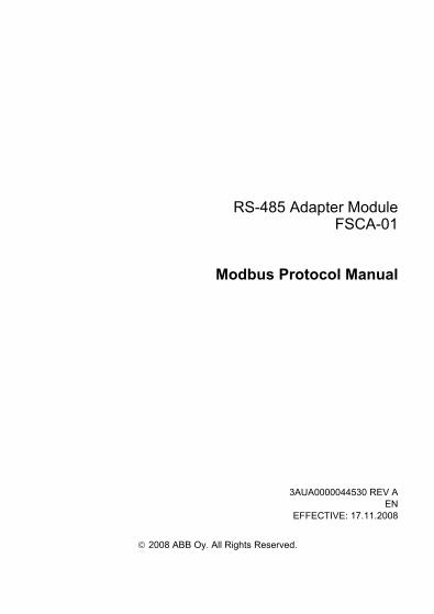
RS-485 Adapter ModuleFSCA-01
Modbus Protocol Manual
3AUA0000044530 REV AEN
EFFECTIVE: 17.11.2008
© 2008 ABB Oy. All Rights Reserved.

5
Safety instructions
OverviewThis chapter states the general safety instructions that must be followed when installing and operating the FSCA-01 RS-485 Adapter Module.
The material in this chapter must be studied before attempting any work on, or with, the unit.
In addition to the safety instructions given below, read the complete safety instructions of the specific drive you are working on.
General safety instructions
WARNING! All electrical installation and maintenance work on the drive should be carried out by qualified electricians.
The drive and adjoining equipment must be properly earthed.
Do not attempt any work on a powered drive. After switching off the mains, always allow the intermediate circuit capacitors 5 minutes to discharge before working on the frequency converter, the motor or the motor cable. It is good practice to check (with a voltage indicating instrument) that the drive is in fact discharged before beginning work.
The motor cable terminals of the drive are at a dangerously high voltage when mains power is applied, regardless of motor operation.
There can be dangerous voltages inside the drive from external control circuits even when the drive mains power is shut off. Exercise appropriate care when working on the unit. Neglecting these instructions can cause physical injury or death.
Safety instructions

6
Safety instructions
7
Table of contents
Safety instructions . . . . . . . . . . . . . . . . . . . . . . . . . . . . . . . . . . . . . . . . . . . . 5
Overview . . . . . . . . . . . . . . . . . . . . . . . . . . . . . . . . . . . . . . . . . . . . . . . . . . . . 5General safety instructions . . . . . . . . . . . . . . . . . . . . . . . . . . . . . . . . . . . . . . . 5
Table of contents . . . . . . . . . . . . . . . . . . . . . . . . . . . . . . . . . . . . . . . . . . . . . 7
Introduction . . . . . . . . . . . . . . . . . . . . . . . . . . . . . . . . . . . . . . . . . . . . . . . . . 9
Intended audience . . . . . . . . . . . . . . . . . . . . . . . . . . . . . . . . . . . . . . . . . . . . . 9Before you start . . . . . . . . . . . . . . . . . . . . . . . . . . . . . . . . . . . . . . . . . . . . . . . 9What this manual contains . . . . . . . . . . . . . . . . . . . . . . . . . . . . . . . . . . . . . . . 9Further information . . . . . . . . . . . . . . . . . . . . . . . . . . . . . . . . . . . . . . . . . . . . 10
Overview . . . . . . . . . . . . . . . . . . . . . . . . . . . . . . . . . . . . . . . . . . . . . . . . . . . 11
Overview . . . . . . . . . . . . . . . . . . . . . . . . . . . . . . . . . . . . . . . . . . . . . . . . . . . 11Modbus/RTU . . . . . . . . . . . . . . . . . . . . . . . . . . . . . . . . . . . . . . . . . . . . . . . . 11Modbus/RTU on FSCA-01 RS-485 Adapter Module . . . . . . . . . . . . . . . . . . 11
Compatibility . . . . . . . . . . . . . . . . . . . . . . . . . . . . . . . . . . . . . . . . . . . . . . . 12
Drive configuration . . . . . . . . . . . . . . . . . . . . . . . . . . . . . . . . . . . . . . . . . . 13
Overview . . . . . . . . . . . . . . . . . . . . . . . . . . . . . . . . . . . . . . . . . . . . . . . . . . . 13Modbus connection configuration . . . . . . . . . . . . . . . . . . . . . . . . . . . . . . . . 13Control locations . . . . . . . . . . . . . . . . . . . . . . . . . . . . . . . . . . . . . . . . . . . . . 21
Master configuration . . . . . . . . . . . . . . . . . . . . . . . . . . . . . . . . . . . . . . . . . 23
Overview . . . . . . . . . . . . . . . . . . . . . . . . . . . . . . . . . . . . . . . . . . . . . . . . . . . 23Configuring the system . . . . . . . . . . . . . . . . . . . . . . . . . . . . . . . . . . . . . . . . 23Modbus register maps . . . . . . . . . . . . . . . . . . . . . . . . . . . . . . . . . . . . . . . . . 23
Table of contents
8
Communication profiles . . . . . . . . . . . . . . . . . . . . . . . . . . . . . . . . . . . . . . . 25
Overview . . . . . . . . . . . . . . . . . . . . . . . . . . . . . . . . . . . . . . . . . . . . . . . . . . . . 25Communication profiles . . . . . . . . . . . . . . . . . . . . . . . . . . . . . . . . . . . . . . . . 25ABB Drives communication profile . . . . . . . . . . . . . . . . . . . . . . . . . . . . . . . . 27
Control Word and Status Word . . . . . . . . . . . . . . . . . . . . . . . . . . . . . . . . . 27References . . . . . . . . . . . . . . . . . . . . . . . . . . . . . . . . . . . . . . . . . . . . . . . . 27Actual values . . . . . . . . . . . . . . . . . . . . . . . . . . . . . . . . . . . . . . . . . . . . . . . 29
Communication . . . . . . . . . . . . . . . . . . . . . . . . . . . . . . . . . . . . . . . . . . . . . . 35
Overview . . . . . . . . . . . . . . . . . . . . . . . . . . . . . . . . . . . . . . . . . . . . . . . . . . . . 35Register addressing . . . . . . . . . . . . . . . . . . . . . . . . . . . . . . . . . . . . . . . . . . . 35Function codes . . . . . . . . . . . . . . . . . . . . . . . . . . . . . . . . . . . . . . . . . . . . . . . 36Encapsulated interface transport / Read device identification . . . . . . . . . . . 37Exception codes . . . . . . . . . . . . . . . . . . . . . . . . . . . . . . . . . . . . . . . . . . . . . . 38Communication profiles . . . . . . . . . . . . . . . . . . . . . . . . . . . . . . . . . . . . . . . . 39
ABB Drives Profile - Classic . . . . . . . . . . . . . . . . . . . . . . . . . . . . . . . . . . . 39ABB Drives Profile - Enhanced . . . . . . . . . . . . . . . . . . . . . . . . . . . . . . . . . 40Transparent 16-bit . . . . . . . . . . . . . . . . . . . . . . . . . . . . . . . . . . . . . . . . . . . 42Transparent 32-bit . . . . . . . . . . . . . . . . . . . . . . . . . . . . . . . . . . . . . . . . . . . 44
Diagnostics . . . . . . . . . . . . . . . . . . . . . . . . . . . . . . . . . . . . . . . . . . . . . . . . . 47
LED indications . . . . . . . . . . . . . . . . . . . . . . . . . . . . . . . . . . . . . . . . . . . . . . . 47Internal error code registers . . . . . . . . . . . . . . . . . . . . . . . . . . . . . . . . . . . . . 48
Definitions . . . . . . . . . . . . . . . . . . . . . . . . . . . . . . . . . . . . . . . . . . . . . . . . . . 49
Table of contents
9
Introduction
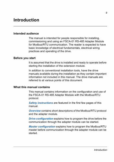
Intended audienceThe manual is intended for people responsible for installing, commissioning and using an FSCA-01 RS-485 Adapter Module for Modbus/RTU communication. The reader is expected to have basic knowledge of electrical fundamentals, electrical wiring practices and operating of the drive.
Before you startIt is assumed that the drive is installed and ready to operate before starting the installation of the extension module.
In addition to conventional installation tools, have the drive manuals available during the installation as they contain important information not included in this manual. The drive manuals are referred to at various points of this document.
What this manual containsThis manual contains information on the configuration and use of the FSCA-01 RS-485 Adapter Module with the Modbus/RTU protocol.
Safety instructions are featured in the first few pages of this manual.
Overview contains short descriptions of the Modbus/RTU protocol and the adapter module.
Drive configuration explains how to program the drive before the communication through the adapter module can be started.
Master configuration explains how to program the Modbus/RTU master before communication through the adapter module can be started.
Introduction
10
Communication profiles describes the communication profiles used in the communication between the Modbus/RTU master, the adapter module and the drive.
Communication contains a description of the Modbus/RTU functionality supported by the adapter module.
Diagnostics explains how to trace faults with the status LEDs on the adapter module.
Definitions explains definitions and abbreviations concerning Modbus/RTU on the adapter module.
Further informationFurther information on the Modbus/RTU protocol is available on the world wide web from www.modbus.org.
Introduction
11
Overview
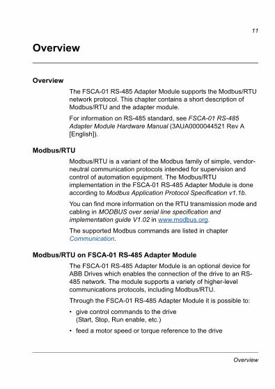
Overview The FSCA-01 RS-485 Adapter Module supports the Modbus/RTU network protocol. This chapter contains a short description of Modbus/RTU and the adapter module.
For information on RS-485 standard, see FSCA-01 RS-485 Adapter Module Hardware Manual (3AUA0000044521 Rev A [English]).
Modbus/RTU Modbus/RTU is a variant of the Modbus family of simple, vendor-neutral communication protocols intended for supervision and control of automation equipment. The Modbus/RTU implementation in the FSCA-01 RS-485 Adapter Module is done according to Modbus Application Protocol Specification v1.1b.
You can find more information on the RTU transmission mode and cabling in MODBUS over serial line specification and implementation guide V1.02 in www.modbus.org.
The supported Modbus commands are listed in chapter Communication.
Modbus/RTU on FSCA-01 RS-485 Adapter ModuleThe FSCA-01 RS-485 Adapter Module is an optional device for ABB Drives which enables the connection of the drive to an RS-485 network. The module supports a variety of higher-level communications protocols, including Modbus/RTU.
Through the FSCA-01 RS-485 Adapter Module it is possible to:
• give control commands to the drive(Start, Stop, Run enable, etc.)
• feed a motor speed or torque reference to the drive
Overview
12
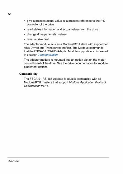
• give a process actual value or a process reference to the PID controller of the drive
• read status information and actual values from the drive
• change drive parameter values
• reset a drive fault.
The adapter module acts as a Modbus/RTU slave with support for ABB Drives and Transparent profiles. The Modbus commands that the FSCA-01 RS-485 Adapter Module supports are discussed in chapter Communication.
The adapter module is mounted into an option slot on the motor control board of the drive. See the drive documentation for module placement options.
CompatibilityThe FSCA-01 RS-485 Adapter Module is compatible with all Modbus/RTU masters that support Modbus Application Protocol Specification v1.1b.
Overview
13
Drive configuration
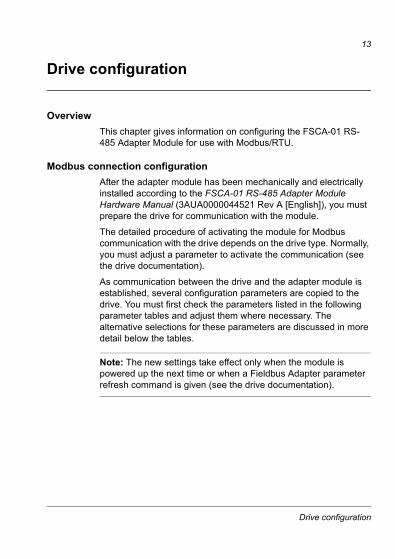
OverviewThis chapter gives information on configuring the FSCA-01 RS-485 Adapter Module for use with Modbus/RTU.
Modbus connection configurationAfter the adapter module has been mechanically and electrically installed according to the FSCA-01 RS-485 Adapter Module Hardware Manual (3AUA0000044521 Rev A [English]), you must prepare the drive for communication with the module.
The detailed procedure of activating the module for Modbus communication with the drive depends on the drive type. Normally, you must adjust a parameter to activate the communication (see the drive documentation).
As communication between the drive and the adapter module is established, several configuration parameters are copied to the drive. You must first check the parameters listed in the following parameter tables and adjust them where necessary. The alternative selections for these parameters are discussed in more detail below the tables.
Note: The new settings take effect only when the module is powered up the next time or when a Fieldbus Adapter parameter refresh command is given (see the drive documentation).
Drive configuration
14
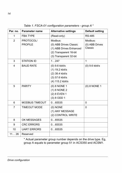
Table 1. FSCA-01 configuration parameters - group A *
* Actual parameter group number depends on the drive type. Eg, group A equals to parameter group 51 in ACS350 and ACSM1.
Par. no. Parameter name Alternative settings Default setting
1 FBA TYPE (Read-only) RS-485
2 PROTOCOL/PROFILE
Modbus:(0) ABB Drives Classic(1) ABB Drives Enhanced(2) Transparent 16-bit(3) Transparent 32-bit
Modbus:(0) ABB Drives Classic
3 STATION ID 1…247 1
4 BAUD RATE (0) 9.6 kbit/s(1) 19.2 kbit/s(2) 38.4 kbit/s(3) 57.6 kbit/s(4) 115.2 kbit/s
(0) 9.6 kbit/s
5 PARITY (0) 8 NONE 1(1) 8 NONE 2(2) 8 EVEN 1(3) 8 ODD 1
(0) 8 NONE 1
6 MODBUS TIMEOUT 0…65535 0
7 TIMEOUT MODE (0) NONE(1) ANY MESSAGE(2) CONTROL WRITE
0
8 OK MESSAGES 0…65535
9 CRC ERRORS 0…65535
10 UART ERRORS 0…65535
11… 26 Reserved
Drive configuration
15
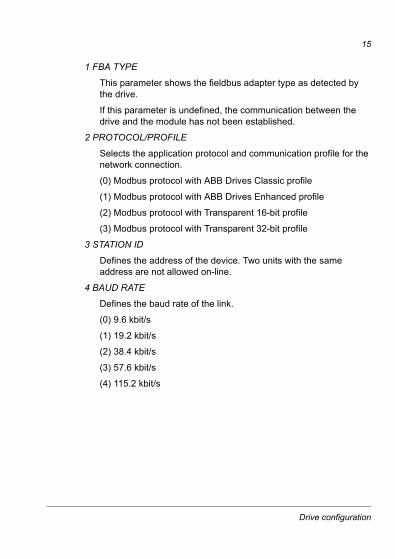
1 FBA TYPE
This parameter shows the fieldbus adapter type as detected by the drive.
If this parameter is undefined, the communication between the drive and the module has not been established.
2 PROTOCOL/PROFILE
Selects the application protocol and communication profile for the network connection.
(0) Modbus protocol with ABB Drives Classic profile
(1) Modbus protocol with ABB Drives Enhanced profile
(2) Modbus protocol with Transparent 16-bit profile
(3) Modbus protocol with Transparent 32-bit profile
3 STATION ID
Defines the address of the device. Two units with the same address are not allowed on-line.
4 BAUD RATE
Defines the baud rate of the link.
(0) 9.6 kbit/s
(1) 19.2 kbit/s
(2) 38.4 kbit/s
(3) 57.6 kbit/s
(4) 115.2 kbit/s
Drive configuration
16
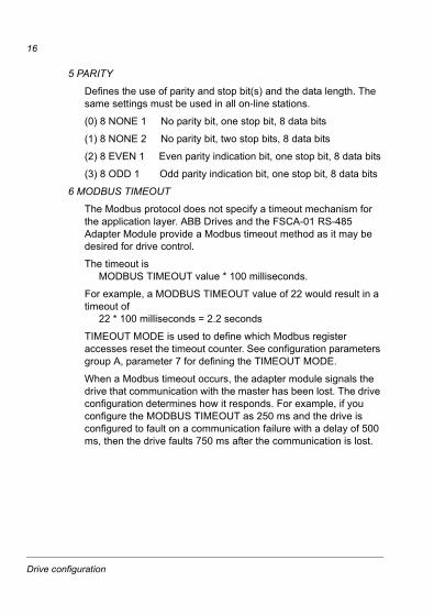
5 PARITY
Defines the use of parity and stop bit(s) and the data length. The same settings must be used in all on-line stations.
(0) 8 NONE 1 No parity bit, one stop bit, 8 data bits
(1) 8 NONE 2 No parity bit, two stop bits, 8 data bits
(2) 8 EVEN 1 Even parity indication bit, one stop bit, 8 data bits
(3) 8 ODD 1 Odd parity indication bit, one stop bit, 8 data bits
6 MODBUS TIMEOUT
The Modbus protocol does not specify a timeout mechanism for the application layer. ABB Drives and the FSCA-01 RS-485 Adapter Module provide a Modbus timeout method as it may be desired for drive control.
The timeout is MODBUS TIMEOUT value * 100 milliseconds.
For example, a MODBUS TIMEOUT value of 22 would result in a timeout of 22 * 100 milliseconds = 2.2 seconds
TIMEOUT MODE is used to define which Modbus register accesses reset the timeout counter. See configuration parameters group A, parameter 7 for defining the TIMEOUT MODE.
When a Modbus timeout occurs, the adapter module signals the drive that communication with the master has been lost. The drive configuration determines how it responds. For example, if you configure the MODBUS TIMEOUT as 250 ms and the drive is configured to fault on a communication failure with a delay of 500 ms, then the drive faults 750 ms after the communication is lost.
Drive configuration
17
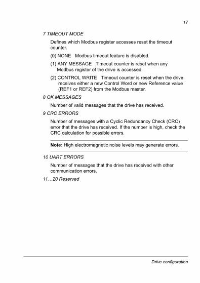
7 TIMEOUT MODE
Defines which Modbus register accesses reset the timeout counter.
(0) NONE Modbus timeout feature is disabled.
(1) ANY MESSAGE Timeout counter is reset when any Modbus register of the drive is accessed.
(2) CONTROL WRITE Timeout counter is reset when the drive receives either a new Control Word or new Reference value (REF1 or REF2) from the Modbus master.
8 OK MESSAGES
Number of valid messages that the drive has received.
9 CRC ERRORS
Number of messages with a Cyclic Redundancy Check (CRC) error that the drive has received. If the number is high, check the CRC calculation for possible errors.
Note: High electromagnetic noise levels may generate errors.
10 UART ERRORS
Number of messages that the drive has received with other communication errors.
11…20 Reserved
Drive configuration
18
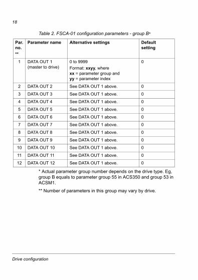
Table 2. FSCA-01 configuration parameters - group B*
* Actual parameter group number depends on the drive type. Eg, group B equals to parameter group 55 in ACS350 and group 53 in ACSM1.
** Number of parameters in this group may vary by drive.
Par. no.**
Parameter name Alternative settings Defaultsetting
1 DATA OUT 1 (master to drive)
0 to 9999Format: xxyy, where xx = parameter group and yy = parameter index
0
2 DATA OUT 2 See DATA OUT 1 above. 0
3 DATA OUT 3 See DATA OUT 1 above. 0
4 DATA OUT 4 See DATA OUT 1 above. 0
5 DATA OUT 5 See DATA OUT 1 above. 0
6 DATA OUT 6 See DATA OUT 1 above. 0
7 DATA OUT 7 See DATA OUT 1 above. 0
8 DATA OUT 8 See DATA OUT 1 above. 0
9 DATA OUT 9 See DATA OUT 1 above. 0
10 DATA OUT 10 See DATA OUT 1 above. 0
11 DATA OUT 11 See DATA OUT 1 above. 0
12 DATA OUT 12 See DATA OUT 1 above. 0
Drive configuration
19
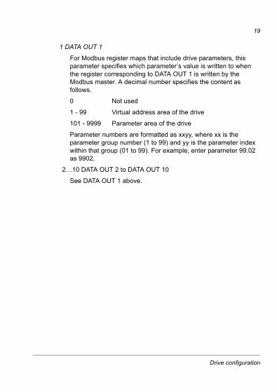
1 DATA OUT 1
For Modbus register maps that include drive parameters, this parameter specifies which parameter’s value is written to when the register corresponding to DATA OUT 1 is written by the Modbus master. A decimal number specifies the content as follows.
0 Not used
1 - 99 Virtual address area of the drive
101 - 9999 Parameter area of the drive
Parameter numbers are formatted as xxyy, where xx is the parameter group number (1 to 99) and yy is the parameter index within that group (01 to 99). For example, enter parameter 99.02 as 9902.
2…10 DATA OUT 2 to DATA OUT 10
See DATA OUT 1 above.
Drive configuration
20
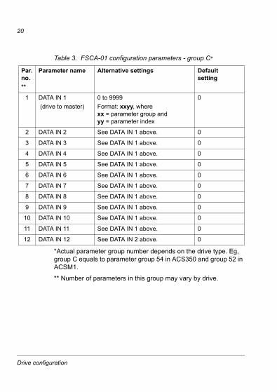
Table 3. FSCA-01 configuration parameters - group C*
*Actual parameter group number depends on the drive type. Eg, group C equals to parameter group 54 in ACS350 and group 52 in ACSM1.
** Number of parameters in this group may vary by drive.
Par. no.**
Parameter name Alternative settings Defaultsetting
1 DATA IN 1 (drive to master)
0 to 9999Format: xxyy, where xx = parameter group and yy = parameter index
0
2 DATA IN 2 See DATA IN 1 above. 0
3 DATA IN 3 See DATA IN 1 above. 0
4 DATA IN 4 See DATA IN 1 above. 0
5 DATA IN 5 See DATA IN 1 above. 0
6 DATA IN 6 See DATA IN 1 above. 0
7 DATA IN 7 See DATA IN 1 above. 0
8 DATA IN 8 See DATA IN 1 above. 0
9 DATA IN 9 See DATA IN 1 above. 0
10 DATA IN 10 See DATA IN 1 above. 0
11 DATA IN 11 See DATA IN 1 above. 0
12 DATA IN 12 See DATA IN 2 above. 0
Drive configuration
21
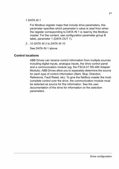
1 DATA IN 1
For Modbus register maps that include drive parameters, this parameter specifies which parameter’s value is read from when the register corresponding to DATA IN 1 is read by the Modbus master. For the content, see configuration parameter group B table, parameter 1 (DATA OUT 1).
2…10 DATA IN 2 to DATA IN 10
See DATA IN 1 above.
Control locationsABB Drives can receive control information from multiple sources including digital inputs, analogue inputs, the drive control panel and a communication module (eg, the FSCA-01 RS-485 Adapter Module). ABB Drives allow you to separately determine the source for each type of control information (Start, Stop, Direction, Reference, Fault Reset, etc). To give the fieldbus master the most complete control over the drive, the communication module must be selected as source for this information. See the user documentation of the drive for information on the selection parameters.
Drive configuration

22
Drive configuration
23
Master configuration
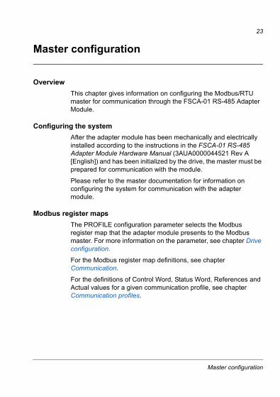
OverviewThis chapter gives information on configuring the Modbus/RTU master for communication through the FSCA-01 RS-485 Adapter Module.
Configuring the systemAfter the adapter module has been mechanically and electrically installed according to the instructions in the FSCA-01 RS-485 Adapter Module Hardware Manual (3AUA0000044521 Rev A [English]) and has been initialized by the drive, the master must be prepared for communication with the module.
Please refer to the master documentation for information on configuring the system for communication with the adapter module.
Modbus register mapsThe PROFILE configuration parameter selects the Modbus register map that the adapter module presents to the Modbus master. For more information on the parameter, see chapter Drive configuration.
For the Modbus register map definitions, see chapter Communication.
For the definitions of Control Word, Status Word, References and Actual values for a given communication profile, see chapter Communication profiles.
Master configuration

24
Master configuration
25
Communication profiles
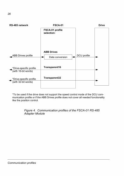
OverviewThis chapter describes the communication profiles used in the communication between the Modbus/RTU master, the FSCA-01 RS-485 Adapter Module and the drive.
Communication profilesThe communication profiles are ways of conveying control commands (Control Word, Status Word, References and Actual values) between the Modbus master and the drive.
You can configure the FSCA-01 RS-485 Adapter Module to provide either the ABB Drives Profile or one of the two Transparent modes for 16 and 32 bit words respectively. For the ABB Drives Profile, the adapter module converts the data to the DCU profile. For detailed information, see the drive documentation. For the Transparent modes, no data conversion takes place.
Communication profiles
26
Figure 4. Communication profiles of the FSCA-01 RS-485 Adapter Module
FSCA-01 Drive
FSCA-01 profile selection:
ABB Drives profile DCU profileData conversion
ABB Drives
*Drive-specific profile(with 16-bit words)
Transparent32*Drive-specific profile(with 32-bit words)
RS-485 network
*To be used if the drive does not support the speed control mode of the DCU com-munication profile or if the ABB Drives profile does not cover all needed functionality like the position control.
Transparent16
Communication profiles
27
ABB Drives communication profile
Control Word and Status WordThe Control Word is the principal means for controlling the drive from a fieldbus system. The fieldbus client station sends the Control Word to the drive through the adapter module. The drive switches between its states according to the bit-coded instructions of the Control Word and returns status information to the client in the Status Word.
The contents of the Control Word and the Status Word are detailed in Tables 7 and 8 respectively. The drive states are presented in the ABB Drives profile state machine (Figure 9).
ReferencesReferences are 16-bit words containing a sign bit and a 15-bit integer. A negative reference (indicating reversed direction of rotation) is formed by calculating the two’s complement from the corresponding positive reference.
ABB Drives can receive control information from multiple sources including analogue and digital inputs, the drive control panel and a communication module (eg, the FSCA-01 RS-485 Adapter Module). To have the drive controlled through the fieldbus, the module must be defined as the source for control information, eg, Reference.
Communication profiles
28
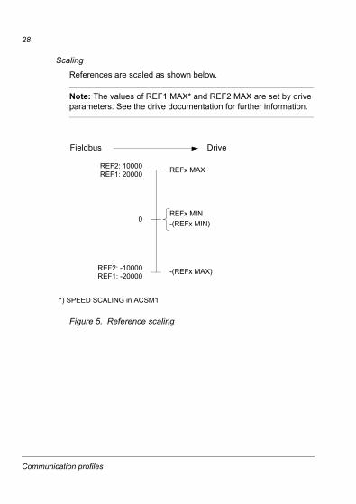
Scaling
References are scaled as shown below.
Note: The values of REF1 MAX* and REF2 MAX are set by drive parameters. See the drive documentation for further information.
Figure 5. Reference scaling
REFx MIN-(REFx MIN)
REFx MAX
-(REFx MAX)
0
REF2: -10000REF1: -20000
REF2: 10000REF1: 20000
DriveFieldbus
*) SPEED SCALING in ACSM1
Communication profiles
29
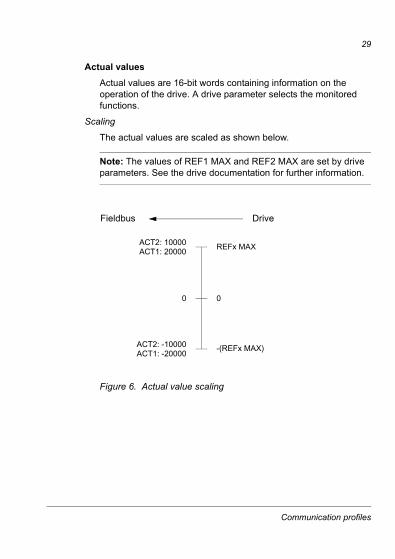
Actual valuesActual values are 16-bit words containing information on the operation of the drive. A drive parameter selects the monitored functions.
Scaling
The actual values are scaled as shown below.
Note: The values of REF1 MAX and REF2 MAX are set by drive parameters. See the drive documentation for further information.
Figure 6. Actual value scaling
0
REFx MAX
-(REFx MAX)
0
ACT2: -10000ACT1: -20000
ACT2: 10000ACT1: 20000
DriveFieldbus
Communication profiles
30
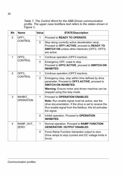
Table 7. The Control Word for the ABB Drives communication profile. The upper case boldface text refers to the states shown in Figure 9.
Bit Name Value STATE/Description
0 OFF1_CONTROL
1 Proceed to READY TO OPERATE.
0 Stop along currently active deceleration ramp. Proceed to OFF1 ACTIVE; proceed to READY TO SWITCH ON unless other interlocks (OFF2, OFF3) are active.
1 OFF2_CONTROL
1 Continue operation (OFF2 inactive).
0 Emergency OFF, coast to stop.Proceed to OFF2 ACTIVE, proceed to SWITCH-ON INHIBITED.
2 OFF3_CONTROL
1 Continue operation (OFF3 inactive).
0 Emergency stop, stop within time defined by drive parameter. Proceed to OFF3 ACTIVE; proceed to SWITCH-ON INHIBITED.Warning: Ensure motor and driven machine can be stopped using this stop mode.
3 INHIBIT_OPERATION
1 Proceed to OPERATION ENABLED.Note: Run enable signal must be active; see the drive documentation. If the drive is set to receive the Run enable signal from the fieldbus, this bit activates the signal.
0 Inhibit operation. Proceed to OPERATION INHIBITED.
4 RAMP_OUT_ZERO
1 Normal operation. Proceed to RAMP FUNCTION GENERATOR: OUTPUT ENABLED.
0 Force Ramp Function Generator output to zero. Drive ramps to stop (current and DC voltage limits in force).
Communication profiles
31
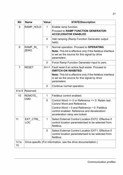
5 RAMP_HOLD 1 Enable ramp function.Proceed to RAMP FUNCTION GENERATOR: ACCELERATOR ENABLED.
0 Halt ramping (Ramp Function Generator output held).
6 RAMP_IN_ZERO
1 Normal operation. Proceed to OPERATING.Note: This bit is effective only if the fieldbus interface is set as the source for this signal by drive parameters.
0 Force Ramp Function Generator input to zero.
7 RESET 0=>1 Fault reset if an active fault exists. Proceed to SWITCH-ON INHIBITED.Note: This bit is effective only if the fieldbus interface is set as the source for this signal by drive parameters.
0 Continue normal operation.
8 to 9 Reserved.
10 REMOTE_CMD
1 Fieldbus control enabled.
0 Control Word <> 0 or Reference <> 0: Retain last Control Word and Reference.Control Word = 0 and Reference = 0: Fieldbus control enabled. Reference and deceleration/acceleration ramp are locked.
11 EXT_CTRL_LOC
1 Select External Control Location EXT2. Effective if control location parameterised to be selected from fieldbus.
0 Select External Control Location EXT1. Effective if control location parameterised to be selected from fieldbus.
12 to 15
Drive-specific (For information, see the drive documentation.)
Bit Name Value STATE/Description
Communication profiles
32
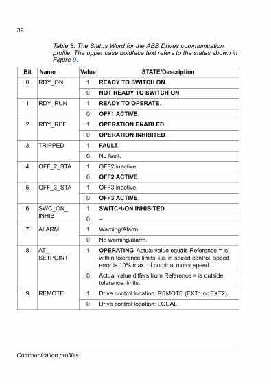
Table 8. The Status Word for the ABB Drives communication profile. The upper case boldface text refers to the states shown in Figure 9.
Bit Name Value STATE/Description
0 RDY_ON 1 READY TO SWITCH ON.
0 NOT READY TO SWITCH ON.
1 RDY_RUN 1 READY TO OPERATE.
0 OFF1 ACTIVE.
2 RDY_REF 1 OPERATION ENABLED.
0 OPERATION INHIBITED.
3 TRIPPED 1 FAULT.
0 No fault.
4 OFF_2_STA 1 OFF2 inactive.
0 OFF2 ACTIVE.
5 OFF_3_STA 1 OFF3 inactive.
0 OFF3 ACTIVE.
6 SWC_ON_INHIB
1 SWITCH-ON INHIBITED.
0 –
7 ALARM 1 Warning/Alarm.
0 No warning/alarm.
8 AT_SETPOINT
1 OPERATING. Actual value equals Reference = is within tolerance limits, i.e. in speed control, speed error is 10% max. of nominal motor speed.
0 Actual value differs from Reference = is outside tolerance limits.
9 REMOTE 1 Drive control location: REMOTE (EXT1 or EXT2).
0 Drive control location: LOCAL.
Communication profiles
33
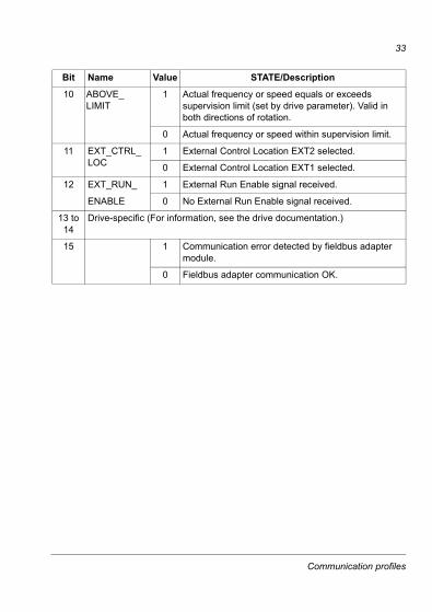
10 ABOVE_LIMIT
1 Actual frequency or speed equals or exceeds supervision limit (set by drive parameter). Valid in both directions of rotation.
0 Actual frequency or speed within supervision limit.
11 EXT_CTRL_LOC
1 External Control Location EXT2 selected.
0 External Control Location EXT1 selected.
12 EXT_RUN_ 1 External Run Enable signal received.
ENABLE 0 No External Run Enable signal received.
13 to 14
Drive-specific (For information, see the drive documentation.)
15 1 Communication error detected by fieldbus adapter module.
0 Fieldbus adapter communication OK.
Bit Name Value STATE/Description
Communication profiles
34
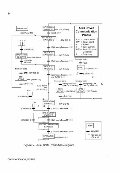
Figure 9. ABB State Transition Diagram
MAINS OFF
Power ON (CW Bit0=0)
(SW Bit6=1)
(SW Bit0=0)
from any state
(CW=xxxx x1xx xxxx x110)
(SW Bit1=1)
n(f)=0 / I=0
(SW Bit2=0)
A B C D
(CW Bit3=0)
operationinhibited
OFF1 (CW Bit0=0)
(SW Bit1=0)
(SW Bit0=1)
(CW Bit3=1and
SW Bit12=1)
C D
(CW Bit5=0)
(SW Bit2=1)
(SW Bit5=0)
from any state from any stateEmergency StopOFF3 (CW Bit2=0)
n(f)=0 / I=0
Emergency OFFOFF2 (CW Bit1=0)
(SW Bit4=0)
B
B C D
(CW Bit4=0)
(CW=xxxx x1xx xxx1 1111)
(CW=xxxx x1xx xx11 1111)
D
(CW Bit6=0)
A
C(CW=xxxx x1xx x111 1111)
(SW Bit8=1)D
from any state
Fault
(SW Bit3=1)
(CW Bit7=1)
(CW=xxxx x1xx xxxx x111)
(CW=xxxx x1xx xxxx 1111and SW Bit12=1)
CW = Control WordSW = Status Wordn = SpeedI = Input CurrentRFG = Ramp Function
Generatorf = Frequency
ABB DrivesCommunication
Profile
SWITCH-ON INHIBITED
NOT READY TO SWITCH ON
READY TO SWITCH ON
READY TO OPERATE
OPERATION INHIBITED
OFF1 ACTIVE
OPERATION ENABLED
RFG: OUTPUT ENABLED
RFG: ACCELERATOR ENABLED
OPERATION
OFF2 ACTIVE
FAULT
OFF3 ACTIVE
state
condition
rising edgethe bitof
Communication profiles
35
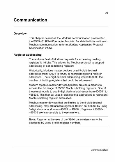
Communication
OverviewThis chapter describes the Modbus communication protocol for the FSCA-01 RS-485 Adapter Module. For detailed information on Modbus communication, refer to Modbus Application Protocol Specification v1.1b.
Register addressingThe address field of Modbus requests for accessing holding registers is 16 bits. This allows the Modbus protocol to support addressing of 65536 holding registers
Historically, Modbus master devices used 5-digit decimal addresses from 40001 to 49999 to represent holding register addresses. The 5-digit decimal addressing limited to 9999 the number of holding registers that could be addressed.
Modern Modbus master devices typically provide a means to access the full range of 65536 Modbus holding registers. One of these methods is to use 6-digit decimal addresses from 400001 to 465536. This manual uses 6-digit decimal addressing to represent Modbus holding register addresses.
Modbus master devices that are limited to the 5-digit decimal addressing, may still access registers 400001 to 409999 by using 5-digit decimal addresses 40001 to 49999. Registers 410000-465536 are inaccessible to these masters.
Note: Register addresses of the 32-bit parameters cannot be accessed by using 5-digit register numbers.
Communication
36
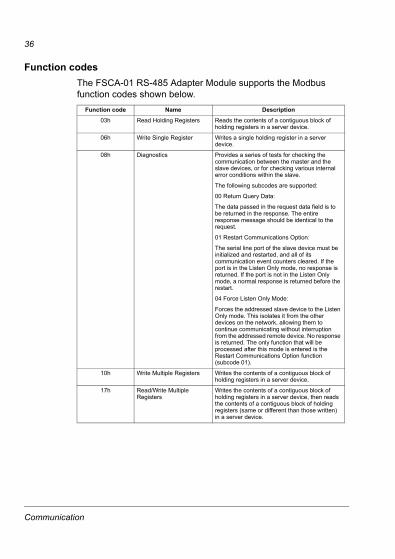
Function codesThe FSCA-01 RS-485 Adapter Module supports the Modbus function codes shown below.
Function code Name Description
03h Read Holding Registers Reads the contents of a contiguous block of holding registers in a server device.
06h Write Single Register Writes a single holding register in a server device.
08h Diagnostics Provides a series of tests for checking the communication between the master and the slave devices, or for checking various internal error conditions within the slave.
The following subcodes are supported:
00 Return Query Data:
The data passed in the request data field is to be returned in the response. The entire response message should be identical to the request.
01 Restart Communications Option:
The serial line port of the slave device must be initialized and restarted, and all of its communication event counters cleared. If the port is in the Listen Only mode, no response is returned. If the port is not in the Listen Only mode, a normal response is returned before the restart.
04 Force Listen Only Mode:
Forces the addressed slave device to the Listen Only mode. This isolates it from the other devices on the network, allowing them to continue communicating without interruption from the addressed remote device. No response is returned. The only function that will be processed after this mode is entered is the Restart Communications Option function (subcode 01).
10h Write Multiple Registers Writes the contents of a contiguous block of holding registers in a server device.
17h Read/Write Multiple Registers
Writes the contents of a contiguous block of holding registers in a server device, then reads the contents of a contiguous block of holding registers (same or different than those written) in a server device.
Communication
37
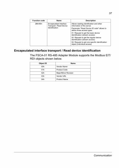
Encapsulated interface transport / Read device identificationThe FSCA-01 RS-485 Adapter Module supports the Modbus EIT/RDI objects shown below.
2Bh/0Eh Encapsulated Interface Transport / Read Device Identification
Allows reading identification and other information of the server. Parameter "Read Device ID code" allows to define three access types:01: Request to get the basic device identification (stream access)02: Request to get the regular device identification (stream access)04: Request to get one specific identification object (individual access)
Object ID Name
00h Vendor Name
01h Product Code
02h Major/Minor Revision
03h Vendor URL
04h Product Name
Function code Name Description
Communication

38
Exception codesThe FSCA-01 RS-485 Adapter Module supports the Modbus exception codes shown below.
Exception code Name Description
01h ILLEGAL FUNCTION The function code received in the query is not an allowable action for the server.
02h ILLEGAL DATA ADDRESSS
The data address received in the query is not an allowable address for the server.
03h ILLEGAL DATA VALUE A value contained in the query data field is not an allowable value for the server.
04h SLAVE DEVICE FAILURE An unrecoverable error occurred while the server was attempting to perform the requested action.
06h SLAVE DEVICE BUSY The slave is engaged in processing a long-duration command. The master should retransmit the message later when the server is free.
Communication
39
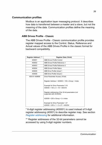
Communication profilesModbus is an application layer messaging protocol. It describes how data is transferred between a master and a slave, but not the meaning of the data. Communication profiles define the meaning of the data.
ABB Drives Profile - ClassicThe ABB Drives Profile - Classic communication profile provides register mapped access to the Control, Status, Reference and Actual values of the ABB Drives Profile in the classic format for backward compatibility.
* 6-digit register addressing (400001) is used instead of 5-digit register addressing (40001) to describe register map. See section Register addressing for additional information.
** Register addresses of the 32-bit parameters cannot be accessed by using 5-digit register numbers.
Register Address*, ** Register Data (16-bit)
400001 ABB Drives Profile Control
400002 ABB Drives Profile Reference 1
400003 ABB Drives Profile Reference 2
400004 ABB Drives Profile Status
400005 ABB Drive Profile Actual 1
400006 ABB Drive Profile Actual 2
400101-409999 Drive Parameter Access (16-bit)
Register Address = 400000 + 100 x Group + Index
Example for Drive Parameter 3.18400000 + 100 x 3 + 18 = 400318
Register addressing of the 32-bit parameters (not supported with ACS350):
420000 + 200 x Group + 2 x Index
Example for Drive Parameter 1.27420000 + 200 x 1 + 2 x 27 = 420254
Communication
40
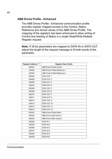
ABB Drives Profile - EnhancedThe ABB Drives Profile - Enhanced communication profile provides register mapped access to the Control, Status, Reference and Actual values of the ABB Drives Profile. The mapping of the registers has been enhanced to allow writing of Control and reading of Status in a single Read/Write Multiple Register request.
Note: If 32-bit parameters are mapped to DATA IN or DATA OUT, adjust the length of the request message to fit both words of the parameter.
Register Address*, ** Register Data (16-bit)
400001 ABB Drives Profile Control
400002 ABB Drives Profile Reference 1
400003 ABB Drives Profile Reference 2
400004 DATA OUT 1
400005 DATA OUT 2
400006 DATA OUT 3
400007 DATA OUT 4
400008 DATA OUT 5
400009 DATA OUT 6
400010 DATA OUT 7
400011 DATA OUT 8
400012 DATA OUT 9
400013 DATA OUT 10
400014 DATA OUT 11
400015 DATA OUT 12
400051 ABB Drives Profile Status
400052 ABB Drive Profile Actual 1
400053 ABB Drive Profile Actual 2
400054 DATA IN 1
400055 DATA IN 2
400056 DATA IN 3
400057 DATA IN 4
400058 DATA IN 5
400059 DATA IN 6
Communication
41
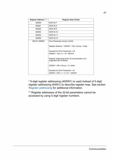
* 6-digit register addressing (400001) is used instead of 5-digit register addressing (40001) to describe register map. See section Register addressing for additional information.
** Register addresses of the 32-bit parameters cannot be accessed by using 5-digit register numbers.
400060 DATA IN 7
400061 DATA IN 8
400062 DATA IN 9
400063 DATA IN 10
400064 DATA IN 11
400065 DATA IN 12
400101-409999 Drive Parameter Access (16-bit)
Register Address = 400000 + 100 x Group + Index
Example for Drive Parameter 3.18400000 + 100 x 3 + 18 = 400318
Register addressing of the 32-bit parameters (not supported with ACS350):
420000 + 200 x Group + 2 x Index
Example for Drive Parameter 1.27420000 + 200 x 1 + 2 x 27 = 420254
Register Address*, ** Register Data (16-bit)
Communication
42
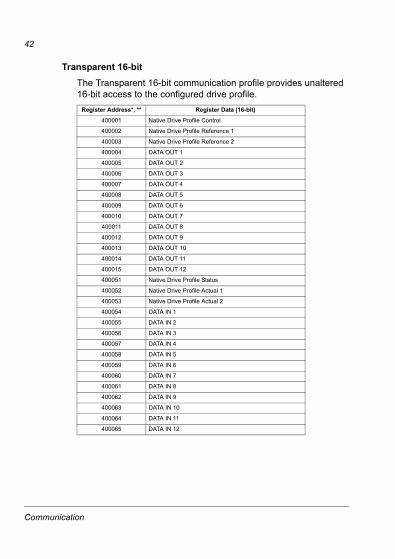
Transparent 16-bitThe Transparent 16-bit communication profile provides unaltered 16-bit access to the configured drive profile.
Register Address*, ** Register Data (16-bit)
400001 Native Drive Profile Control
400002 Native Drive Profile Reference 1
400003 Native Drive Profile Reference 2
400004 DATA OUT 1
400005 DATA OUT 2
400006 DATA OUT 3
400007 DATA OUT 4
400008 DATA OUT 5
400009 DATA OUT 6
400010 DATA OUT 7
400011 DATA OUT 8
400012 DATA OUT 9
400013 DATA OUT 10
400014 DATA OUT 11
400015 DATA OUT 12
400051 Native Drive Profile Status
400052 Native Drive Profile Actual 1
400053 Native Drive Profile Actual 2
400054 DATA IN 1
400055 DATA IN 2
400056 DATA IN 3
400057 DATA IN 4
400058 DATA IN 5
400059 DATA IN 6
400060 DATA IN 7
400061 DATA IN 8
400062 DATA IN 9
400063 DATA IN 10
400064 DATA IN 11
400065 DATA IN 12
Communication
43
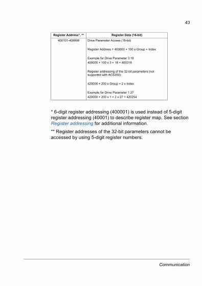
* 6-digit register addressing (400001) is used instead of 5-digit register addressing (40001) to describe register map. See section Register addressing for additional information.
** Register addresses of the 32-bit parameters cannot be accessed by using 5-digit register numbers.
400101-409999 Drive Parameter Access (16-bit)
Register Address = 400000 + 100 x Group + Index
Example for Drive Parameter 3.18400000 + 100 x 3 + 18 = 400318
Register addressing of the 32-bit parameters (not supported with ACS350):
420000 + 200 x Group + 2 x Index
Example for Drive Parameter 1.27420000 + 200 x 1 + 2 x 27 = 420254
Register Address*, ** Register Data (16-bit)
Communication
44
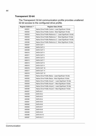
Transparent 32-bitThe Transparent 32-bit communication profile provides unaltered 32-bit access to the configured drive profile.
Register Address*,** Register Data (16-bit)
400001 Native Drive Profile Control - Least Significant 16-bits
400002 Native Drive Profile Control - Most Significant 16-bits
400003 Native Drive Profile Reference 1 - Least Significant 16-bits
400004 Native Drive Profile Reference 1 - Most Significant 16-bits
400005 Native Drive Profile Reference 2 - Least Significant 16-bits
400006 Native Drive Profile Reference 2 - Most Significant 16-bits
400007 DATA OUT 1
400008 DATA OUT 2
400009 DATA OUT 3
400010 DATA OUT 4
400011 DATA OUT 5
400012 DATA OUT 6
400013 DATA OUT 7
400014 DATA OUT 8
400015 DATA OUT 9
400016 DATA OUT 10
400017 DATA OUT 11
400018 DATA OUT 12
400051 Native Drive Profile Status - Least Significant 16-bits
400052 Native Drive Profile Status - Most Significant 16-bits
400053 Native Drive Profile Actual 1 - Least Significant 16-bits
400054 Native Drive Profile Actual 1 - Most Significant 16-bits
400055 Native Drive Profile Actual 2 - Least Significant 16-bits
400056 Native Drive Profile Actual 2 - Most Significant 16-bits
400057 DATA IN 1
400058 DATA IN 2
400059 DATA IN 3
400060 DATA IN 4
400061 DATA IN 5
400062 DATA IN 6
400063 DATA IN 7
400064 DATA IN 8
400065 DATA IN 9
400066 DATA IN 10
400067 DATA IN 11
Communication
45
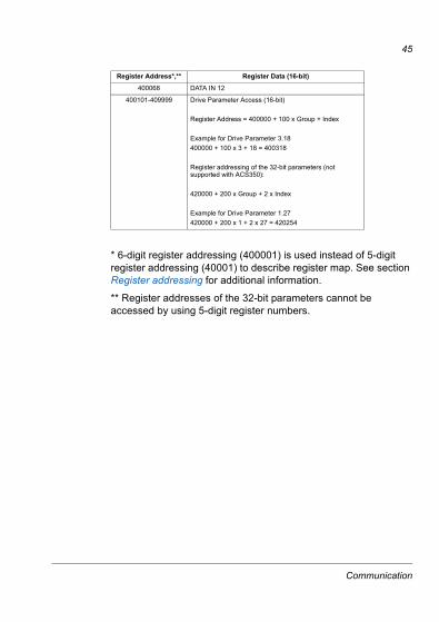
* 6-digit register addressing (400001) is used instead of 5-digit register addressing (40001) to describe register map. See section Register addressing for additional information.
** Register addresses of the 32-bit parameters cannot be accessed by using 5-digit register numbers.
400068 DATA IN 12
400101-409999 Drive Parameter Access (16-bit)
Register Address = 400000 + 100 x Group + Index
Example for Drive Parameter 3.18400000 + 100 x 3 + 18 = 400318
Register addressing of the 32-bit parameters (not supported with ACS350):
420000 + 200 x Group + 2 x Index
Example for Drive Parameter 1.27420000 + 200 x 1 + 2 x 27 = 420254
Register Address*,** Register Data (16-bit)
Communication

46
Communication
47
Diagnostics
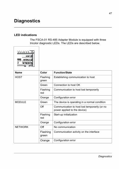
LED indicationsThe FSCA-01 RS-485 Adapter Module is equipped with three tricolor diagnostic LEDs. The LEDs are described below.
Name Color Function/State
HOST Flashing green
Establishing communication to host
Green Connection to host OK
Flashing red
Communication to host lost temporarily
Orange Configuration error
MODULE Green The device is operating in a normal condition
Off Communication to host lost temporarily (or no power applied to the device)
Flashing red
Start-up initialization
Orange Configuration error
NETWORK Off No communication
Flashing green
Communication activity on the interface
Orange Configuration error
Diagnostics
48
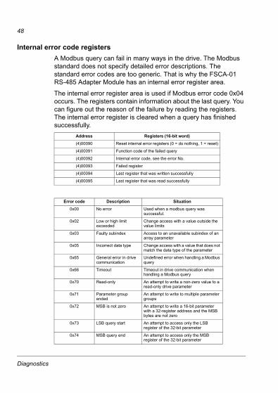
Internal error code registersA Modbus query can fail in many ways in the drive. The Modbus standard does not specify detailed error descriptions. The standard error codes are too generic. That is why the FSCA-01 RS-485 Adapter Module has an internal error register area.
The internal error register area is used if Modbus error code 0x04 occurs. The registers contain information about the last query. You can figure out the reason of the failure by reading the registers. The internal error register is cleared when a query has finished successfully.
Address Registers (16-bit word)
(4)00090 Reset internal error registers (0 = do nothing, 1 = reset)
(4)00091 Function code of the failed query
(4)00092 Internal error code, see the error No.
(4)00093 Failed register
(4)00094 Last register that was written successfully
(4)00095 Last register that was read successfully
Error code Description Situation
0x00 No error Used when a modbus query was successful.
0x02 Low or high limit exceeded
Change access with a value outside the value limits
0x03 Faulty subindex Access to an unavailable subindex of an array parameter
0x05 Incorrect data type Change access with a value that does not match the data type of the parameter
0x65 General error in drive communication
Undefined error when handling a Modbus query
0x66 Timeout Timeout in drive communication when handling a Modbus query
0x70 Read-only An attempt to write a non-zero value to a read-only drive parameter
0x71 Parameter group ended
An attempt to write to multiple parameter groups
0x72 MSB is not zero An attempt to write a 16-bit parameter with a 32-register address and the MSB bytes are not zero
0x73 LSB query start An attempt to access only the LSB register of the 32-bit parameter
0x74 MSB query end An attempt to access only the MSB register of the 32-bit parameter
Diagnostics
49
Definitions
Communication Module
Communication Module is a name for a device (eg, a fieldbus adapter) through which the drive is connected to an external serial communication network (eg, a fieldbus). A drive parameter activates the communication with the communication module.
Parameter
A parameter is an operating instruction for the drive. Parameters can be read and programmed using the drive control panel, or through the FSCA-01 RS-485 Adapter Module.
Definitions

50
Definitions

ABB OyAC DrivesP.O. Box 184FI-00381 HELSINKIFINLANDTelephone +358 10 22 11Fax +358 10 22 22681Internet http://www.abb.com
ABB Inc.Automation TechnologiesDrives & Motors16250 West Glendale DriveNew Berlin, WI 53151USATelephone 262 785-3200
800-HELP-365Fax 262 780-5135
3AU
A00
0004
4530
RE
V A
EN
EFF
EC
TIV
E: 1
7.11
.200
8

![INTERPRETATION OF STATUTES TRAINING [RE-ISSUE] · training in interpretation of statutes for 40 delegates of the FSCA. 5. Background 5.1 The FSCA has identified a need to provide](https://img.pdfslide.us/doc/110x75/5e78455783be2a65cc5c830b/interpretation-of-statutes-training-re-issue-training-in-interpretation-of-statutes.jpg)


![SUPPLY, DELIVER AND OFFLOAD DIESEL TO THE FSCA … · TITLE FSCA201920-R008 [SUPPLY, DELIVER AND OFFLOAD DIESEL TO THE FSCA GENERATORS] [RE-ISSUE][30 MAY 2019] INITIAL HERE BIDDER’S](https://img.pdfslide.us/doc/110x75/5ffb2b3decafa87a0542d5fd/supply-deliver-and-offload-diesel-to-the-fsca-title-fsca201920-r008-supply-deliver.jpg)