Embed Size (px)
Citation preview

ABB Drives
Hardware ManualRS-485 Adapter ModuleFSCA-01

RS-485 Adapter ModuleFSCA-01
Hardware Manual
3AUA0000044521 REV AEN
EFFECTIVE: 17.11.2008
© 2008 ABB Oy. All Rights Reserved.


5
Safety instructions
OverviewThis chapter states the general safety instructions that must be followed when installing and operating the FSCA-01 RS-485 Adapter Module.
The material in this chapter must be studied before attempting any work on, or with, the unit.
In addition to the safety instructions given below, read the complete safety instructions of the specific drive you are working on.
General safety instructions
WARNING! All electrical installation and maintenance work on the drive should be carried out by qualified electricians.
The drive and adjoining equipment must be properly earthed.
Do not attempt any work on a powered drive. After switching off the mains, always allow the intermediate circuit capacitors 5 minutes to discharge before working on the frequency converter, the motor or the motor cable. It is good practice to check (with a voltage indicating instrument) that the drive is in fact discharged before beginning work.
The motor cable terminals of the drive are at a dangerously high voltage when mains power is applied, regardless of motor operation.
There can be dangerous voltages inside the drive from external control circuits even when the drive mains power is shut off. Exercise appropriate care when working on the unit. Neglecting these instructions can cause physical injury or death.
Safety instructions

6
Safety instructions

7
Table of contents
Safety instructions . . . . . . . . . . . . . . . . . . . . . . . . . . . . . . . . . . . . . . . . . . . . 5
Overview . . . . . . . . . . . . . . . . . . . . . . . . . . . . . . . . . . . . . . . . . . . . . . . . . . . . 5General safety instructions . . . . . . . . . . . . . . . . . . . . . . . . . . . . . . . . . . . . . . . 5
Table of contents . . . . . . . . . . . . . . . . . . . . . . . . . . . . . . . . . . . . . . . . . . . . . 7
Introduction . . . . . . . . . . . . . . . . . . . . . . . . . . . . . . . . . . . . . . . . . . . . . . . . . 9
Intended audience . . . . . . . . . . . . . . . . . . . . . . . . . . . . . . . . . . . . . . . . . . . . . 9Before you start . . . . . . . . . . . . . . . . . . . . . . . . . . . . . . . . . . . . . . . . . . . . . . . 9What this manual contains . . . . . . . . . . . . . . . . . . . . . . . . . . . . . . . . . . . . . . 10
Overview . . . . . . . . . . . . . . . . . . . . . . . . . . . . . . . . . . . . . . . . . . . . . . . . . . . 11
Overview . . . . . . . . . . . . . . . . . . . . . . . . . . . . . . . . . . . . . . . . . . . . . . . . . . . 11RS-485 standard . . . . . . . . . . . . . . . . . . . . . . . . . . . . . . . . . . . . . . . . . . . . . 11FSCA-01 RS-485 Adapter Module . . . . . . . . . . . . . . . . . . . . . . . . . . . . . . . . 12
Compatibility . . . . . . . . . . . . . . . . . . . . . . . . . . . . . . . . . . . . . . . . . . . . . . . 13Delivery check . . . . . . . . . . . . . . . . . . . . . . . . . . . . . . . . . . . . . . . . . . . . . 13
Mechanical installation . . . . . . . . . . . . . . . . . . . . . . . . . . . . . . . . . . . . . . . 15
Mounting . . . . . . . . . . . . . . . . . . . . . . . . . . . . . . . . . . . . . . . . . . . . . . . . . . . 15
Electrical installation . . . . . . . . . . . . . . . . . . . . . . . . . . . . . . . . . . . . . . . . . 17
Overview . . . . . . . . . . . . . . . . . . . . . . . . . . . . . . . . . . . . . . . . . . . . . . . . . . . 17General cabling instructions . . . . . . . . . . . . . . . . . . . . . . . . . . . . . . . . . . . . . 17RS-485 connection . . . . . . . . . . . . . . . . . . . . . . . . . . . . . . . . . . . . . . . . . . . . 17Bus termination . . . . . . . . . . . . . . . . . . . . . . . . . . . . . . . . . . . . . . . . . . . . . . 18
Technical data . . . . . . . . . . . . . . . . . . . . . . . . . . . . . . . . . . . . . . . . . . . . . . 19
FSCA-01 . . . . . . . . . . . . . . . . . . . . . . . . . . . . . . . . . . . . . . . . . . . . . . . . . . . 19
Table of contents

8
RS-485 link . . . . . . . . . . . . . . . . . . . . . . . . . . . . . . . . . . . . . . . . . . . . . . . . . . 20
Definitions . . . . . . . . . . . . . . . . . . . . . . . . . . . . . . . . . . . . . . . . . . . . . . . . . . 21
Table of contents

9
Introduction
Intended audienceThe manual is intended for people responsible for installing, commissioning and using the FSCA-01 RS-485 Adapter Module. The reader is expected to have a basic knowledge of electrical fundamentals, electrical wiring practices and operating of the drive.
Before you startIt is assumed that the drive is installed and ready to operate before starting the installation of the extension module.
In addition to conventional installation tools, have the drive manuals available during the installation as they contain important information not included in this manual. The drive manuals are referred to at various points of this document.
Introduction

10
What this manual containsThis manual contains information on the wiring and installation of the FSCA-01 RS-485 Adapter Module.
Safety instructions are featured in the first few pages of this manual.
Overview contains short descriptions of the RS-485 networking, the adapter module and a delivery checklist.
Mechanical installation contains placing and mounting instructions for the module.
Electrical installation contains wiring, bus termination and earthing instructions.
Technical data contains information on physical dimensions, configurable settings and connectors of the module.
Definitions explains definitions and abbreviations concerning the FSCA-01 RS-485 Adapter Module and RS-485.
Introduction

11
Overview
Overview This chapter contains a short description of the RS-485 standard and the FSCA-01 RS-485 Adapter Module, and a delivery checklist.
RS-485 standardRS-485 is a serial interface standard for communication over a twisted-pair cable. Because the RS-485 signal transmission is differential, it provides better protection against noise and longer transmission distances than the RS-232. RS-485 is a half-duplex multi-drop network, which means that multiple devices may reside on line. Only one transmitter may be active at any given time.
The RS-485 standard specifies only the electrical characteristics of the bus system. The communication protocol and communication speed depend on the used application. For example, the electrical characteristics of the PROFIBUS and MODBUS are based on the RS-485 standard.
The RS-485 transmission line consists of two wires, A and B. The signal transmission is based on the voltage difference between the wires. The minimum detected voltage difference is 200 mV. The potential difference between the two wires determines the logic state bit: when B is at a higher voltage than A, the state is defined as bit 1 (data high) and when A is at a higher voltage than B, the state is defined as bit 0 (data low).
The common mode voltage between RS-485 network devices is limited to -5…+12 V. A ground wire and cable shield should be connected to prevent the common mode voltage between the network devices from drifting outside the allowable limits.
The RS-485 bus cable should be terminated with a 120 ohm resistor on both ends to prevent signal reflection. When no device on the network is transmitting, noise can be falsely interpreted as
Overview

12
communication data. To avoid this, a termination can be included with a fail-safe circuit (pull-up and pull-down resistors). The circuit forces the bus into a known idle state when no device is transmitting.
FSCA-01 RS-485 Adapter ModuleThe FSCA-01 RS-485 Adapter Module is an optional device for ABB Drives which enables the connection of the drive to a RS-485 network. The adapter module provides galvanic isolation between the drive and RS-485 network and converts the serial communication signals of the drive to the RS-485 signal levels.
The adapter module has a built-in bus termination with fail-safe circuitry. The termination can be activated with a jumper.
The adapter module is mounted into an option slot on the motor control board of the drive. See the drive documentation for module placement options.
Protocols used to access these functionalities over RS-485 connection (for example, Modbus/RTU) and configuration of the FSCA-01 RS-485 Adapter Module to use them are described in the respective Protocol Manual.
Overview
13
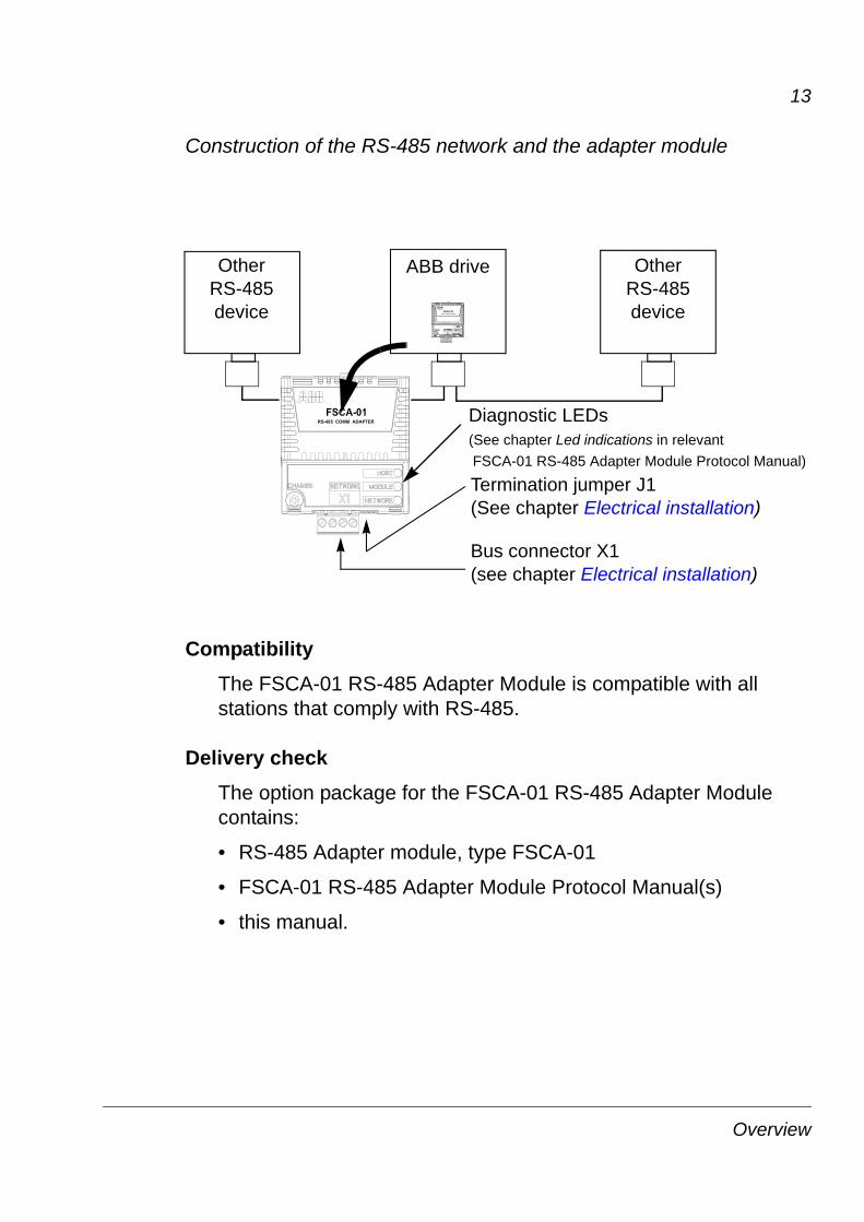
Construction of the RS-485 network and the adapter module
CompatibilityThe FSCA-01 RS-485 Adapter Module is compatible with all stations that comply with RS-485.
Delivery checkThe option package for the FSCA-01 RS-485 Adapter Module contains:
• RS-485 Adapter module, type FSCA-01
• FSCA-01 RS-485 Adapter Module Protocol Manual(s)
• this manual.
Bus connector X1(see chapter Electrical installation)
Diagnostic LEDs(See chapter Led indications in relevant
Other RS-485 device
ABB drive Other RS-485 device
Termination jumper J1(See chapter Electrical installation)
FSCA-01 RS-485 Adapter Module Protocol Manual)
Overview

14
Overview
15
Mechanical installation
WARNING! Follow the safety instructions given in this manual and the drive documentation.
MountingInsert the FSCA-01 RS-485 Adapter Module into an available fieldbus adapter slot. Hold the module in place with plastic pins and one screw. The screw also provides the electrical connection between the module and drive frame for cable shield termination.
On installation of the module, the signal and power connection to the drive is made through a 20-pin connector. (All drives do not use all the available signals so the connector on the drive may have fewer pins.)
Mounting procedure:
• Insert the module carefully into its position on the drive.
• Fasten the screw.
Note: Correct installation of the screw is essential for fulfilling the EMC requirements and for proper operation of the module.
Mechanical installation
16
Mechanical installation

17
Electrical installation
OverviewThis chapter contains:
• general cabling instructions
• instructions for connecting the FSCA-01 RS-485 Adapter Module to the RS-485 network
• instructions for setting the bus termination.
WARNING! Before installation, switch off the drive power supply. Wait 5 minutes to ensure that the capacitor bank of the drive is discharged. Switch off all dangerous voltages connected from external control circuits to the inputs and outputs of the drive.
General cabling instructionsArrange the bus cables as far away from the motor cables as possible. Avoid parallel runs. Use bushings at cable entries.
RS-485 connectionConnect the RS-485 cable to connector X1 on the FSCA-01 RS-485 Adapter Module.
X1 Description
1 SHLD Bus cable shield. Connected internally to GND_B via an RC filter and directly to CH_GND (chassis).
2 DATA_B Data positive
3 DATA_A Data negative
4 GND_B Isolated signal ground
1 2 3 4
Electrical installation

18
Bus terminationBus termination is required to prevent signal reflections from the bus cable ends. The FSCA-01 RS-485 Adapter Module is equipped with internal bus termination, which is configurable with jumper J1 pins. Termination should be activated on devices located at bus ends and deactivated on other devices. See the figure below.
RS-485 device
ON
RS-485 device
OFF
RS-485 device
ONOFFTerm. Term. Term. Term.
J1
Terminationactivated
Terminationactivated
Terminationdeactivated
Terminationdeactivated
J1J1 J1
RS-485 device
Electrical installation

19
Technical data
FSCA-01Enclosure:
Mounting: Into the option slot on the drive
Degree of protection: IP20
Ambient conditions: The applicable ambient conditions specified for the drive in its manuals are in effect.
Indicators: Three LEDs (HOST, MODULE, NETWORK)
Connectors:• 20-pin connector to drive
• 4-pin detachable screw connector to bus
• 6-pin jumper block for bus termination configuration.
Technical data

20
Power supply: +3.3 V ±5% max. 400 mA (supplied by the drive)
General:• Estimated min. lifetime: 100 000 h
• All materials UL/CSA-approved
• Complies with EMC standards EN 61000-6-4:2001 and EN 61800-3
• Bus interface functionally isolated from drive.
RS-485 linkCompatible Devices: All RS-485 compliant devices
Medium: Shielded twisted pair cable, impedance 100 to 150 ohm
• Termination: 120 ohms (built in the FSCA-01 RS-485 Adapter Module)
Topology: Trunk line, drop lines allowed
Serial Communication Type: Asynchronous, half-duplex RS-485
Protocol: Depends on the used application. Typically Modbus.
Technical data

21
Definitions
Communication Module
Communication Module is a name for a device (for example, a fieldbus adapter) through which the drive is connected to an external serial communication network (for example, a fieldbus). The communication with the communication module is activated by a drive parameter.
FSCA-01 RS-485 Adapter Module
The FSCA-01 RS-485 Adapter Module is one of the optional fieldbus adapter modules available for ABB Drives. The FSCA-01 RS-485 Adapter Module is a device through which an ABB drive is connected to an RS-485 network.
Parameter
A parameter is an operating instruction for the drive. Parameters can be read and programmed using the drive control panel, or through the FSCA-01 RS-485 Adapter Module.
Definitions

22
Definitions


ABB OyAC DrivesP.O. Box 184FI-00381 HELSINKIFINLANDTelephone +358 10 22 11Fax +358 10 22 22681Internet http://www.abb.com
ABB Inc.Automation TechnologiesDrives & Motors16250 West Glendale DriveNew Berlin, WI 53151USATelephone 262 785-3200
800-HELP-365Fax 262 780-5135
3AU
A00
0004
4521
RE
V A
EN
EFF
EC
TIV
E: 1
7.11
.200
8


![SUPPLY, DELIVER AND OFFLOAD DIESEL TO THE FSCA … · TITLE FSCA201920-R008 [SUPPLY, DELIVER AND OFFLOAD DIESEL TO THE FSCA GENERATORS] [RE-ISSUE][30 MAY 2019] INITIAL HERE BIDDER’S](https://img.pdfslide.us/doc/110x75/5ffb2b3decafa87a0542d5fd/supply-deliver-and-offload-diesel-to-the-fsca-title-fsca201920-r008-supply-deliver.jpg)


![WELCOME [infinitus.co.za]€¦ · certificate Will send steps ... (FSCA), announced that the Financial Services Board (FSB) had been “transformed” into the FSCA as of 1 April](https://img.pdfslide.us/doc/110x75/5fbf5772848b0b7e9575f515/welcome-certificate-will-send-steps-fsca-announced-that-the-financial.jpg)