Embed Size (px)
Citation preview

cod.
354
0M63
0 —
07/
2008
(Re
v. 0
0)
ENERGY TOP B
INSTRUCTIONS FOR USE, INSTALLATION AND MAINTENANCE
B
Declaration of conformityManufacturer: FERROLI S.p.A.
Address: Via Ritonda 78/a 37047 San Bonifacio VR Italy
declares that this unit complies with the following EU directives:• Gas Appliance Directive 90/396• Efficiency Directive 92/42• Low Voltage Directive 73/23 (amended by 93/68)• Electromagnetic Compatibility Directive 89/336 (amended by 93/68)
President and Legal Representative Cav. del Lavoro
Dante Ferroli
B This symbol indicates "Caution" and is placed next to all safety warnings. Strictly followthese instructions in order to avoid danger and damage to persons, animals and things.
A This symbols calls attention to a note or important notice.
ENERGY TOP B
51ENcod. 3540M630 - 07/2008 (Rev. 00)
• Carefully read the warnings in this instruction book-let since they provide important information on safeinstallation, use and maintenance.
• This instruction booklet is an integral part of theproduct and must be carefully kept by the user for fu-ture reference.
• If the unit is sold or transferred to another owner or ifit is to be moved, always make sure that the bookletaccompanies the boiler so that it can be consultedby the new owner and/or installer.
• Installation and maintenance must be carried out byprofessionally qualified personnel, according to cur-rent regulations and the manufacturer's instructions.
• Incorrect installation or poor maintenance can causedamage or physical injury. The manufacturer de-clines any responsibility for damage caused by er-rors in installation and use or by failure to follow themanufacturer's instructions.
• Before carrying out any cleaning or maintenance op-eration, disconnect the unit from the electrical powersupply using the switch and/or the special cut-off de-vices.
• In case the unit breaks down and/or functions poorly,deactivate it, do not make any attempt to repair it ordirectly intervene. Contact professionally qualifiedpersonnel. Any repair/replacement of products mustonly be carried out by qualified professional person-nel using exclusively genuine parts. Failure to com-ply with the above could affect the safety of the unit.
• Periodical maintenance carried out by qualified per-sonnel is essential for guaranteeing good operationof the unit.
• This unit must only be used for the purpose for whichit was designed. Any other use is considered im-proper and therefore hazardous.
• After removing the packing, check the integrity of thecontents. Packing materials must not be left within thereach of children as they are potentially hazardous.
• In case of doubt do not use the unit, and contact thesupplier.
• The images shown in this manual are a simplifiedrepresentation of the product. In this representationthere may be slight, unimportant differences with thesupplied product.
ENERGY TOP B
52cod. 3540M630 - 07/2008 (Rev. 00)
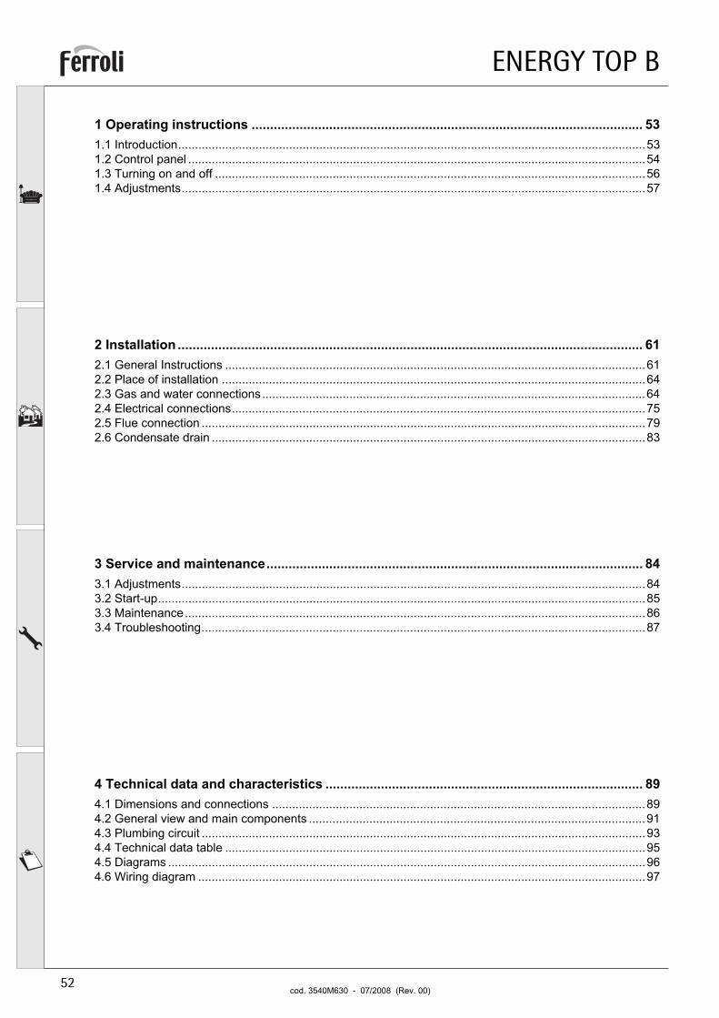
1 Operating instructions .......................................................................................................... 531.1 Introduction...........................................................................................................................................531.2 Control panel ........................................................................................................................................541.3 Turning on and off ................................................................................................................................561.4 Adjustments..........................................................................................................................................57
2 Installation .............................................................................................................................. 612.1 General Instructions .............................................................................................................................612.2 Place of installation ..............................................................................................................................642.3 Gas and water connections..................................................................................................................642.4 Electrical connections...........................................................................................................................752.5 Flue connection ....................................................................................................................................792.6 Condensate drain .................................................................................................................................83
3 Service and maintenance...................................................................................................... 843.1 Adjustments..........................................................................................................................................843.2 Start-up.................................................................................................................................................853.3 Maintenance.........................................................................................................................................863.4 Troubleshooting....................................................................................................................................87
4 Technical data and characteristics ...................................................................................... 894.1 Dimensions and connections ...............................................................................................................894.2 General view and main components ....................................................................................................914.3 Plumbing circuit ....................................................................................................................................934.4 Technical data table .............................................................................................................................954.5 Diagrams ..............................................................................................................................................964.6 Wiring diagram .....................................................................................................................................97
ENERGY TOP B
53ENcod. 3540M630 - 07/2008 (Rev. 00)
1. Operating instructions1.1 Introduction
Dear Customer,
Thank you for choosing ENERGY TOP B, a latest-generation heat generator featuring FERROLIadvanced design andcutting-edge technology. Please read this manual carefully since it provides important information on safe installation,use and maintenance.
ENERGY TOP B is a high-efficiency modular premix condensing heat generator for heating with very low emissions, running on natural gas or LPG and arranged for installation in cascade.
Each module ENERGY TOP B is equipped with one (version ENERGY TOP B 80 - 125) or two (version ENERGY TOPB 160 - 250) aluminium finned tube exchangers with steel premix burners, housed in a vertical cabinet in epoxy powdercoated steel resistant to atmospheric agents.
The plumbing circuits of the exchangers, each equipped with its own local circulating pump, run into system deliveryand return manifolds inside the module. The control system has a microprocessor, user interface with a large displayand advanced cascade control functions.
ENERGY TOP B
54 ENcod. 3540M630 - 07/2008 (Rev. 00)
1.2 Control panel
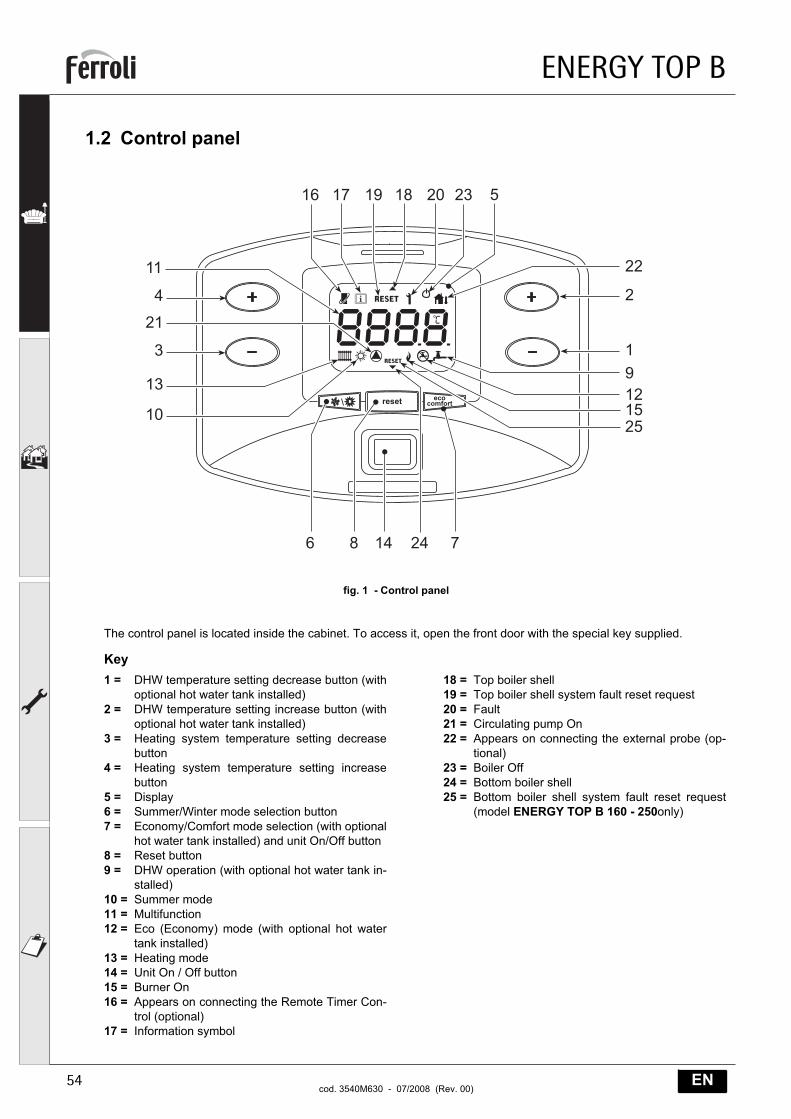
fig. 1 - Control panel
The control panel is located inside the cabinet. To access it, open the front door with the special key supplied.
Key1 = DHW temperature setting decrease button (with
optional hot water tank installed)2 = DHW temperature setting increase button (with
optional hot water tank installed)3 = Heating system temperature setting decrease
button4 = Heating system temperature setting increase
button5 = Display6 = Summer/Winter mode selection button7 = Economy/Comfort mode selection (with optional
hot water tank installed) and unit On/Off button8 = Reset button9 = DHW operation (with optional hot water tank in-
stalled)10 = Summer mode11 = Multifunction12 = Eco (Economy) mode (with optional hot water
tank installed)13 = Heating mode14 = Unit On / Off button15 = Burner On16 = Appears on connecting the Remote Timer Con-
trol (optional)17 = Information symbol
18 = Top boiler shell19 = Top boiler shell system fault reset request20 = Fault21 = Circulating pump On22 = Appears on connecting the external probe (op-
tional)23 = Boiler Off24 = Bottom boiler shell25 = Bottom boiler shell system fault reset request
(model ENERGY TOP B 160 - 250only)
�� �� ����
�
�
��
�
���
��
�
��
��
� ��
��
�
�
����
����� ���������
�
��
ENERGY TOP B
55ENcod. 3540M630 - 07/2008 (Rev. 00)
Indication during operation
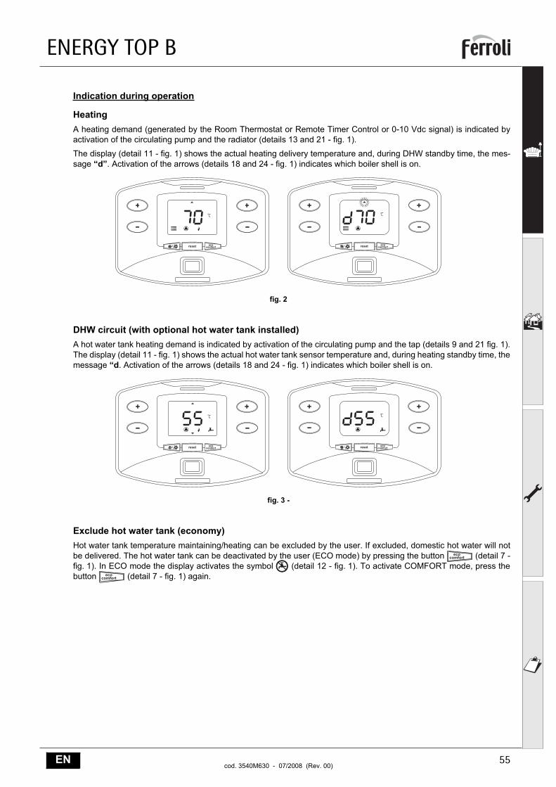
HeatingA heating demand (generated by the Room Thermostat or Remote Timer Control or 0-10 Vdc signal) is indicated byactivation of the circulating pump and the radiator (details 13 and 21 - fig. 1).
The display (detail 11 - fig. 1) shows the actual heating delivery temperature and, during DHW standby time, the mes-sage “d”. Activation of the arrows (details 18 and 24 - fig. 1) indicates which boiler shell is on.
fig. 2
DHW circuit (with optional hot water tank installed)A hot water tank heating demand is indicated by activation of the circulating pump and the tap (details 9 and 21 fig. 1).The display (detail 11 - fig. 1) shows the actual hot water tank sensor temperature and, during heating standby time, themessage “d. Activation of the arrows (details 18 and 24 - fig. 1) indicates which boiler shell is on.
fig. 3 -
Exclude hot water tank (economy)Hot water tank temperature maintaining/heating can be excluded by the user. If excluded, domestic hot water will notbe delivered. The hot water tank can be deactivated by the user (ECO mode) by pressing the button (detail 7 -fig. 1). In ECO mode the display activates the symbol (detail 12 - fig. 1). To activate COMFORT mode, press thebutton (detail 7 - fig. 1) again.
����� ��������� ����� ���
������
����� ��������� ����� ���
������
ENERGY TOP B
56 ENcod. 3540M630 - 07/2008 (Rev. 00)
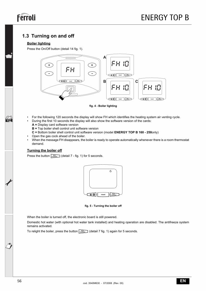
1.3 Turning on and offBoiler lightingPress the On/Off button (detail 14 fig. 1).
fig. 4 - Boiler lighting
• For the following 120 seconds the display will show FH which identifies the heating system air venting cycle.• During the first 10 seconds the display will also show the software version of the cards:
A = Display card software versionB = Top boiler shell control unit software versionC = Bottom boiler shell control unit software version (model ENERGY TOP B 160 - 250only)
• Open the gas cock ahead of the boiler.• When the message FH disappears, the boiler is ready to operate automatically whenever there is a room thermostat
demand.
Turning the boiler offPress the button (detail 7 - fig. 1) for 5 seconds.
fig. 5 - Turning the boiler off
When the boiler is turned off, the electronic board is still powered.
Domestic hot water (with optional hot water tank installed) and heating operation are disabled. The antifreeze systemremains activated.
To relight the boiler, press the button (detail 7 fig. 1) again for 5 seconds.
����� ���������
����� ���������
����� ���������
����� ���������
�
�
����� ���������
ENERGY TOP B
57ENcod. 3540M630 - 07/2008 (Rev. 00)
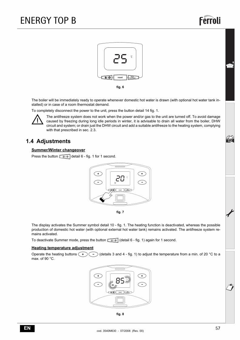
fig. 6
The boiler will be immediately ready to operate whenever domestic hot water is drawn (with optional hot water tank in-stalled) or in case of a room thermostat demand.
To completely disconnect the power to the unit, press the button detail 14 fig. 1.
BThe antifreeze system does not work when the power and/or gas to the unit are turned off. To avoid damagecaused by freezing during long idle periods in winter, it is advisable to drain all water from the boiler, DHWcircuit and system; or drain just the DHW circuit and add a suitable antifreeze to the heating system, complyingwith that prescribed in sec. 2.3.
1.4 AdjustmentsSummer/Winter changeoverPress the button detail 6 - fig. 1 for 1 second.
fig. 7
The display activates the Summer symbol detail 10 - fig. 1. The heating function is deactivated, whereas the possibleproduction of domestic hot water (with optional external hot water tank) remains activated. The antifreeze system re-mains activated.
To deactivate Summer mode, press the button (detail 6 - fig. 1) again for 1 second.
Heating temperature adjustmentOperate the heating buttons (details 3 and 4 - fig. 1) to adjust the temperature from a min. of 20 °C to amax. of 90 °C.
fig. 8
����� ���������
����� ���������
����� ���������
���������������
����������������
���
ENERGY TOP B
58 ENcod. 3540M630 - 07/2008 (Rev. 00)
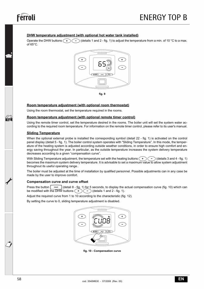
DHW temperature adjustment (with optional hot water tank installed)Operate the DHW buttons (details 1 and 2 - fig. 1) to adjust the temperature from a min. of 10 °C to a max.of 65°C.
fig. 9
Room temperature adjustment (with optional room thermostat)Using the room thermostat, set the temperature required in the rooms.
Room temperature adjustment (with optional remote timer control)Using the remote timer control, set the temperature desired in the rooms. The boiler unit will set the system water ac-cording to the required room temperature. For information on the remote timer control, please refer to its user's manual.
Sliding TemperatureWhen the optional external probe is installed the corresponding symbol (detail 22 - fig. 1) is activated on the controlpanel display (detail 5 - fig. 1). The boiler control system operates with "Sliding Temperature”. In this mode, the temper-ature of the heating system is adjusted according outside weather conditions, in order to ensure high comfort and en-ergy saving throughout the year. In particular, as the outside temperature increases the system delivery temperaturedecreases according to a given “compensation curve”.
With Sliding Temperature adjustment, the temperature set with the heating buttons (details 3 and 4 - fig. 1)becomes the maximum system delivery temperature. It is advisable to set a maximum value to allow system adjustmentthroughout its useful operating range..
The boiler must be adjusted at the time of installation by qualified personnel. Possible adjustments can in any case bemade by the user to improve comfort.
Compensation curve and curve offsetPress the button (detail 8 - fig. 1) for 5 seconds, to display the actual compensation curve (fig. 10) which canbe modified with the DHW buttons (details 1 and 2 - fig. 1).
Adjust the required curve from 1 to 10 according to the characteristic (fig. 12).
By setting the curve to 0, sliding temperature adjustment is disabled.
fig. 10 - Compensation curve
����� ���������
���������������
�����
����� ���������
���������������
����������������
ENERGY TOP B
59ENcod. 3540M630 - 07/2008 (Rev. 00)
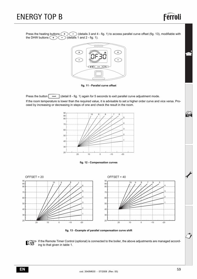
Press the heating buttons (details 3 and 4 - fig. 1) to access parallel curve offset (fig. 13), modifiable withthe DHW buttons (details 1 and 2 - fig. 1).
fig. 11 - Parallel curve offset
Press the button (detail 8 - fig. 1) again for 5 seconds to exit parallel curve adjustment mode.
If the room temperature is lower than the required value, it is advisable to set a higher order curve and vice versa. Pro-ceed by increasing or decreasing in steps of one and check the result in the room.
fig. 12 - Compensation curves
fig. 13 - Example of parallel compensation curve shift
AIf the Remote Timer Control (optional) is connected to the boiler, the above adjustments are managed accord-ing to that given in table 1.
����� ���������
�����������������
�����������������
�����
��
��
��
��
�
��
��
���
�� �� � ��� ���
�
�
�
�
�
��� �
��
��
��
��
�
��
��
���
�� �� � ��� ���
�
�
�
�
�
��� �
�� �� � ��� �����
��
��
��
�
��
��
���
�
�
�
����� �
����������� �����������
ENERGY TOP B
60 ENcod. 3540M630 - 07/2008 (Rev. 00)
Table. 1
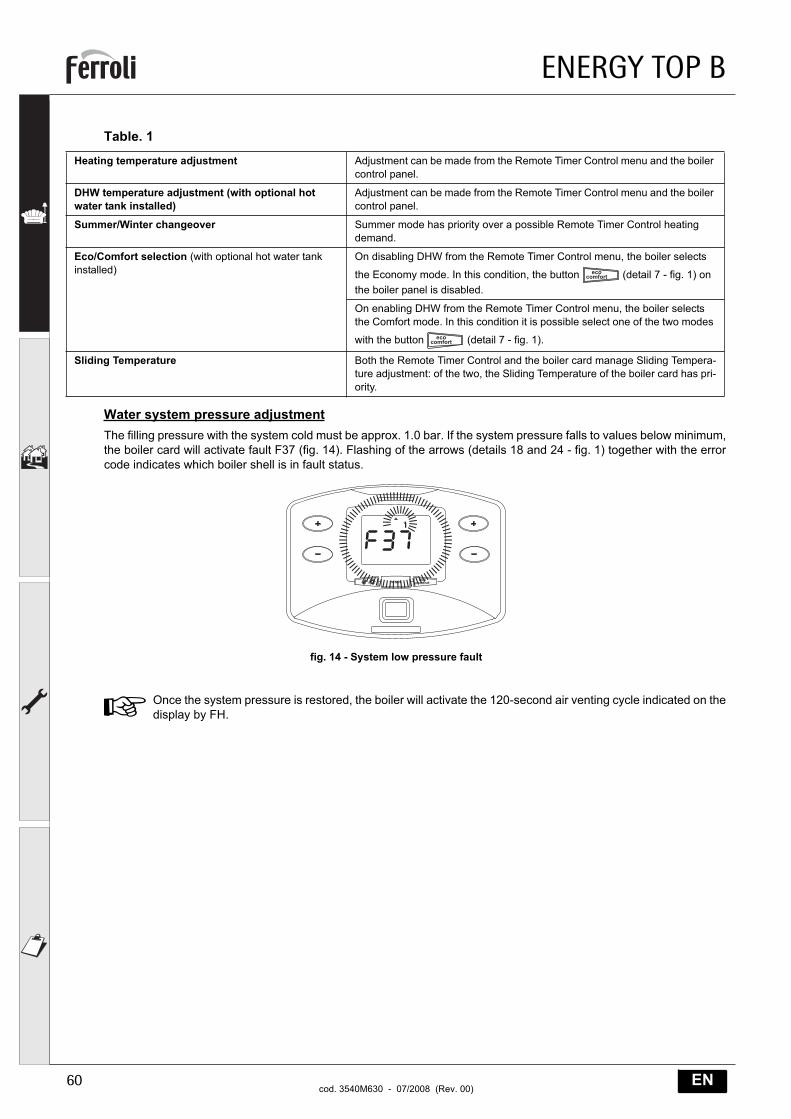
Water system pressure adjustmentThe filling pressure with the system cold must be approx. 1.0 bar. If the system pressure falls to values below minimum,the boiler card will activate fault F37 (fig. 14). Flashing of the arrows (details 18 and 24 - fig. 1) together with the errorcode indicates which boiler shell is in fault status.
fig. 14 - System low pressure fault
AOnce the system pressure is restored, the boiler will activate the 120-second air venting cycle indicated on thedisplay by FH.
Heating temperature adjustment Adjustment can be made from the Remote Timer Control menu and the boiler control panel.
DHW temperature adjustment (with optional hot water tank installed)
Adjustment can be made from the Remote Timer Control menu and the boiler control panel.
Summer/Winter changeover Summer mode has priority over a possible Remote Timer Control heating demand.
Eco/Comfort selection (with optional hot water tank installed)
On disabling DHW from the Remote Timer Control menu, the boiler selects
the Economy mode. In this condition, the button (detail 7 - fig. 1) on the boiler panel is disabled.
On enabling DHW from the Remote Timer Control menu, the boiler selects the Comfort mode. In this condition it is possible select one of the two modes
with the button (detail 7 - fig. 1).
Sliding Temperature Both the Remote Timer Control and the boiler card manage Sliding Tempera-ture adjustment: of the two, the Sliding Temperature of the boiler card has pri-ority.
����� ���������
������������������
�������������
���������
������
�������
�������������������������������������������������������
ENERGY TOP B
61ENcod. 3540M630 - 07/2008 (Rev. 00)
2. Installation2.1 General Instructions
THE BOILER MUST ONLY BE INSTALLED BY QUALIFIED PERSONNEL, IN COMPLIANCE WITH ALL THE IN-STRUCTIONS GIVEN IN THIS TECHNICAL MANUAL, THE PROVISIONS OF CURRENT LAW, THE NATIONAL ANDLOCAL REGULATIONS, AND THE RULES OF PROPER WORKMANSHIP.
ENERGY TOP B is a heat generator arranged to operate alone or in cascade (bank). When two or more generatorsare installed in cascade with the original kits ENERGY TOP B, respecting the prescriptionsFERROLIof this manual,they can be considered as a single heat generator of total power equal to the sum of the powers of all the units con-nected in cascade.
All the requirements of the current standards and regulations applicable to this “equivalent” total heating capacity gen-erator must be met. In particular, the place of installation, safety devices and fume exhaust system must be adequatefor the total heating capacity of the bank of units.
In fact, each ENERGY TOP B is a complete and independent heat generator, equipped with its own safety devices. Incase of overtemperature, no water or no circulation in the unit , the protection devices cause the unit to shutdown , pre-venting its operation.
The installation instructions given in the following sections concern both the single unit and connection in cascade.
Given below are the possible configurations for connection in cascade.
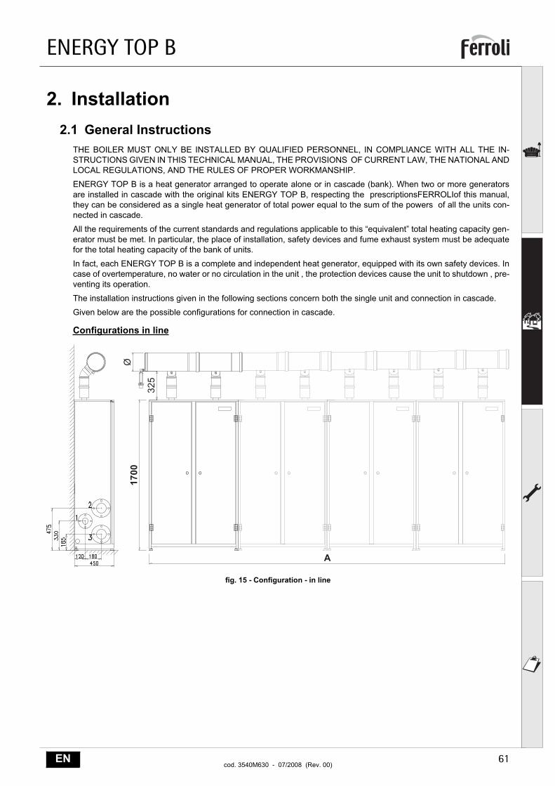
Configurations in line
fig. 15 - Configuration - in line
����
�
���
�
ENERGY TOP B
62 ENcod. 3540M630 - 07/2008 (Rev. 00)
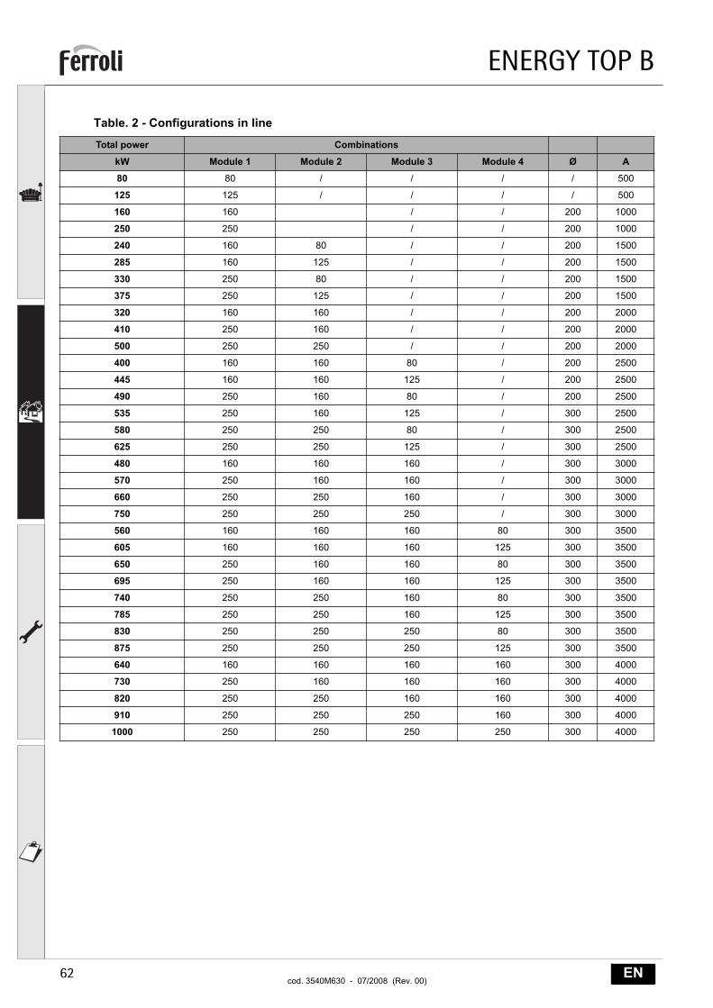
Table. 2 - Configurations in line
Total power Combinations
kW Module 1 Module 2 Module 3 Module 4 Ø A
80 80 / / / / 500
125 125 / / / / 500
160 160 / / 200 1000
250 250 / / 200 1000
240 160 80 / / 200 1500
285 160 125 / / 200 1500
330 250 80 / / 200 1500
375 250 125 / / 200 1500
320 160 160 / / 200 2000
410 250 160 / / 200 2000
500 250 250 / / 200 2000
400 160 160 80 / 200 2500
445 160 160 125 / 200 2500
490 250 160 80 / 200 2500
535 250 160 125 / 300 2500
580 250 250 80 / 300 2500
625 250 250 125 / 300 2500
480 160 160 160 / 300 3000
570 250 160 160 / 300 3000
660 250 250 160 / 300 3000
750 250 250 250 / 300 3000
560 160 160 160 80 300 3500
605 160 160 160 125 300 3500
650 250 160 160 80 300 3500
695 250 160 160 125 300 3500
740 250 250 160 80 300 3500
785 250 250 160 125 300 3500
830 250 250 250 80 300 3500
875 250 250 250 125 300 3500
640 160 160 160 160 300 4000
730 250 160 160 160 300 4000
820 250 250 160 160 300 4000
910 250 250 250 160 300 4000
1000 250 250 250 250 300 4000
ENERGY TOP B
63ENcod. 3540M630 - 07/2008 (Rev. 00)
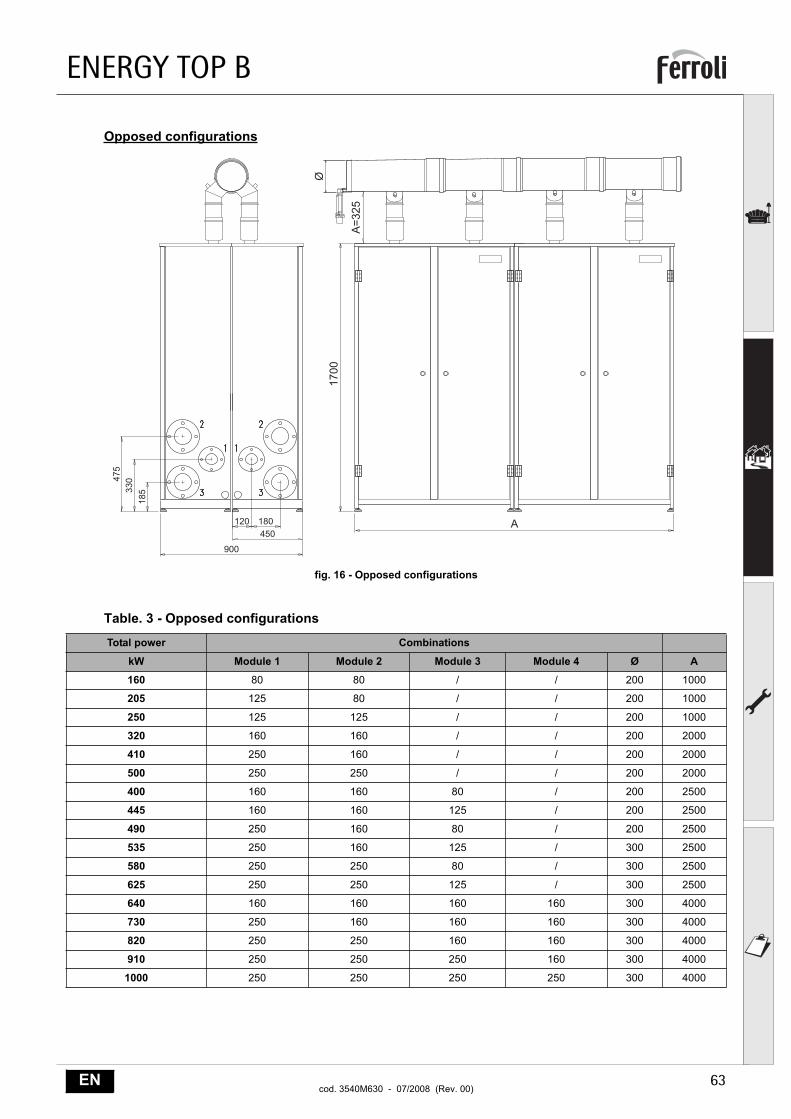
Opposed configurations
fig. 16 - Opposed configurations
Table. 3 - Opposed configurations
Total power Combinations
kW Module 1 Module 2 Module 3 Module 4 Ø A
160 80 80 / / 200 1000
205 125 80 / / 200 1000
250 125 125 / / 200 1000
320 160 160 / / 200 2000
410 250 160 / / 200 2000
500 250 250 / / 200 2000
400 160 160 80 / 200 2500
445 160 160 125 / 200 2500
490 250 160 80 / 200 2500
535 250 160 125 / 300 2500
580 250 250 80 / 300 2500
625 250 250 125 / 300 2500
640 160 160 160 160 300 4000
730 250 160 160 160 300 4000
820 250 250 160 160 300 4000
910 250 250 250 160 300 4000
1000 250 250 250 250 300 4000
����
���
��
�
�
���������
���
���
���
��
ENERGY TOP B
64 ENcod. 3540M630 - 07/2008 (Rev. 00)
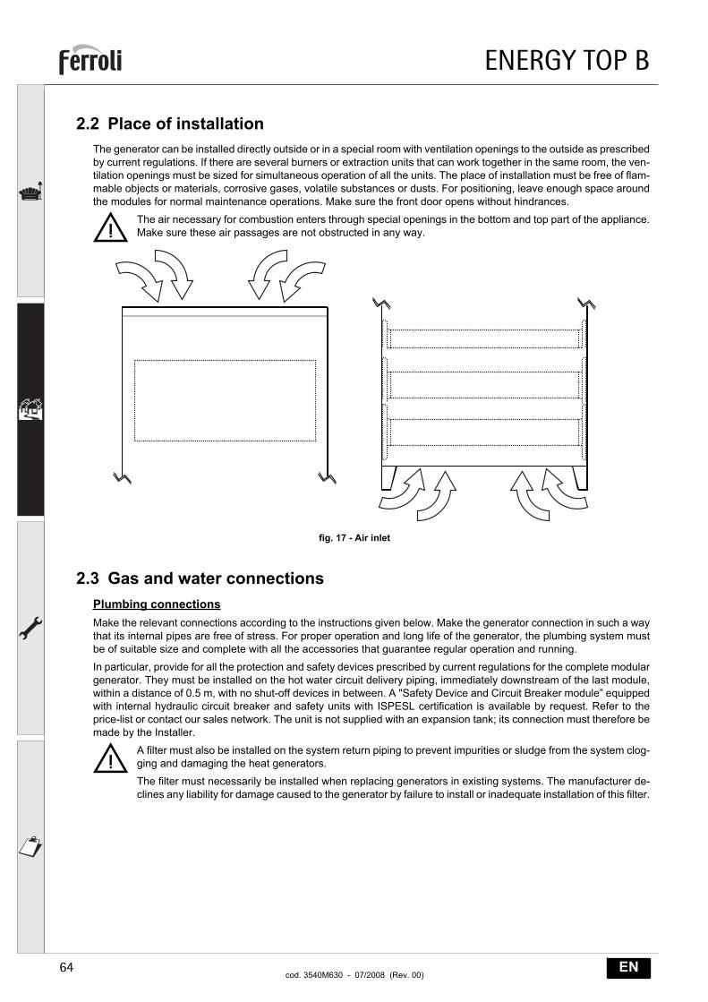
2.2 Place of installationThe generator can be installed directly outside or in a special room with ventilation openings to the outside as prescribedby current regulations. If there are several burners or extraction units that can work together in the same room, the ven-tilation openings must be sized for simultaneous operation of all the units. The place of installation must be free of flam-mable objects or materials, corrosive gases, volatile substances or dusts. For positioning, leave enough space aroundthe modules for normal maintenance operations. Make sure the front door opens without hindrances.
BThe air necessary for combustion enters through special openings in the bottom and top part of the appliance.Make sure these air passages are not obstructed in any way.
fig. 17 - Air inlet
2.3 Gas and water connectionsPlumbing connectionsMake the relevant connections according to the instructions given below. Make the generator connection in such a waythat its internal pipes are free of stress. For proper operation and long life of the generator, the plumbing system mustbe of suitable size and complete with all the accessories that guarantee regular operation and running.
In particular, provide for all the protection and safety devices prescribed by current regulations for the complete modulargenerator. They must be installed on the hot water circuit delivery piping, immediately downstream of the last module,within a distance of 0.5 m, with no shut-off devices in between. A "Safety Device and Circuit Breaker module” equippedwith internal hydraulic circuit breaker and safety units with ISPESL certification is available by request. Refer to theprice-list or contact our sales network. The unit is not supplied with an expansion tank; its connection must therefore bemade by the Installer.
BA filter must also be installed on the system return piping to prevent impurities or sludge from the system clog-ging and damaging the heat generators.
The filter must necessarily be installed when replacing generators in existing systems. The manufacturer de-clines any liability for damage caused to the generator by failure to install or inadequate installation of this filter.
ENERGY TOP B
65ENcod. 3540M630 - 07/2008 (Rev. 00)
Water system characteristicsIn the presence of water harder than 25° Fr, it is advisable to use suitably treated water, in order to avoid possible scalingin the boiler caused by hard water, or corrosion produced by aggressive water. Due to its low thermal conductivity, scal-ing even just a few mm thick causes significant overheating of the generator walls, with consequent serious problems.
Water treatment is indispensable in case of very large systems (containing large amounts of water) or with frequent in-troduction of replenishing water in the system. If partial or total emptying of the system becomes necessary in thesecases, it is advisable to refill with treated water.
Gas connectionThe gas must be connected to the corresponding union with a rigid metal pipe.
The gas meter must be adequate for the simultaneous use of all units connected to it. Carry out the generator gas con-nection in accordance with current regulations. The diameter of the gas pipe leaving the generator does not determinethe diameter of the pipe between the unit and the meter; it must be chosen according to its length and pressure loss.
BMake sure to install a fuel shutoff valve externally with respect to the modules, enabling the gas to be turnedoff even without opening the single modules equipped with key closing.
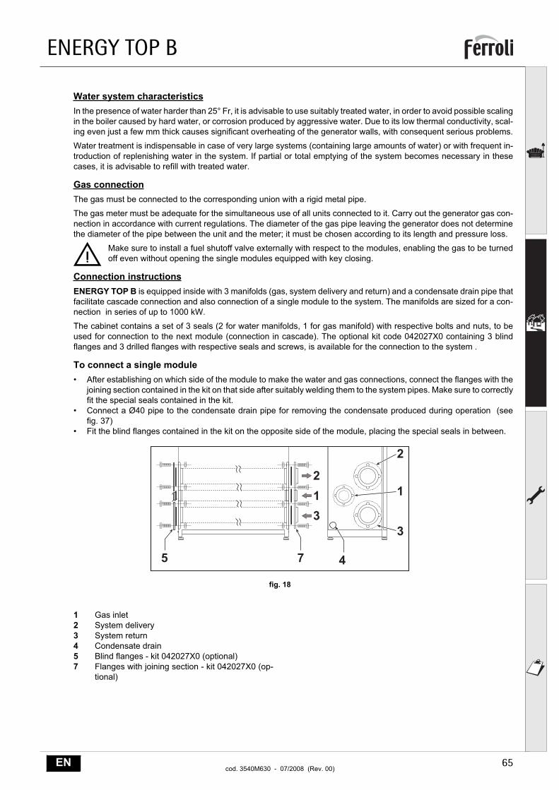
Connection instructionsENERGY TOP B is equipped inside with 3 manifolds (gas, system delivery and return) and a condensate drain pipe thatfacilitate cascade connection and also connection of a single module to the system. The manifolds are sized for a con-nection in series of up to 1000 kW.
The cabinet contains a set of 3 seals (2 for water manifolds, 1 for gas manifold) with respective bolts and nuts, to beused for connection to the next module (connection in cascade). The optional kit code 042027X0 containing 3 blindflanges and 3 drilled flanges with respective seals and screws, is available for the connection to the system .
To connect a single module• After establishing on which side of the module to make the water and gas connections, connect the flanges with the
joining section contained in the kit on that side after suitably welding them to the system pipes. Make sure to correctlyfit the special seals contained in the kit.
• Connect a Ø40 pipe to the condensate drain pipe for removing the condensate produced during operation (seefig. 37)
• Fit the blind flanges contained in the kit on the opposite side of the module, placing the special seals in between.
fig. 18
1 Gas inlet2 System delivery3 System return4 Condensate drain5 Blind flanges - kit 042027X0 (optional)7 Flanges with joining section - kit 042027X0 (op-
tional)
�
�
�
���
�
�
�
ENERGY TOP B
66 ENcod. 3540M630 - 07/2008 (Rev. 00)
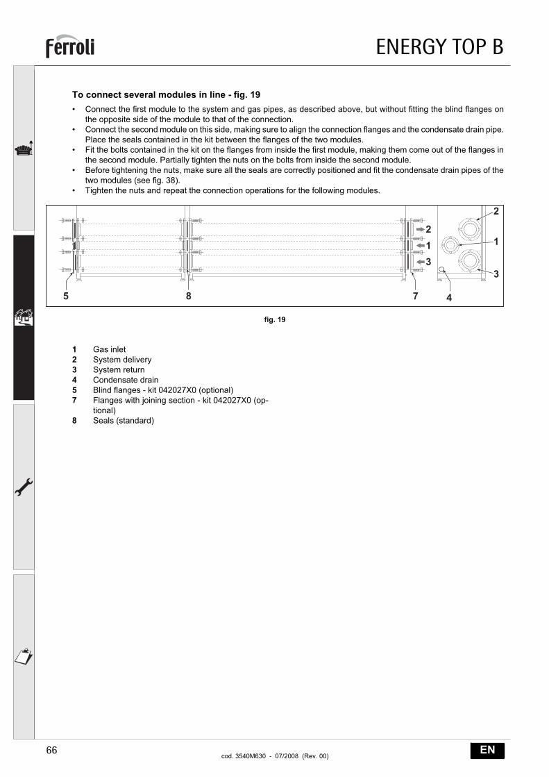
To connect several modules in line - fig. 19• Connect the first module to the system and gas pipes, as described above, but without fitting the blind flanges on
the opposite side of the module to that of the connection.• Connect the second module on this side, making sure to align the connection flanges and the condensate drain pipe.
Place the seals contained in the kit between the flanges of the two modules.• Fit the bolts contained in the kit on the flanges from inside the first module, making them come out of the flanges in
the second module. Partially tighten the nuts on the bolts from inside the second module.• Before tightening the nuts, make sure all the seals are correctly positioned and fit the condensate drain pipes of the
two modules (see fig. 38).• Tighten the nuts and repeat the connection operations for the following modules.
fig. 19
1 Gas inlet2 System delivery3 System return4 Condensate drain5 Blind flanges - kit 042027X0 (optional)7 Flanges with joining section - kit 042027X0 (op-
tional)8 Seals (standard)
�
�
�
��
�
�
�
��
ENERGY TOP B
67ENcod. 3540M630 - 07/2008 (Rev. 00)
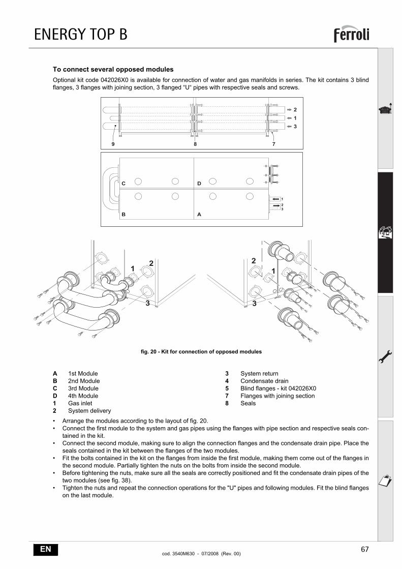
To connect several opposed modulesOptional kit code 042026X0 is available for connection of water and gas manifolds in series. The kit contains 3 blindflanges, 3 flanges with joining section, 3 flanged “U“ pipes with respective seals and screws.
fig. 20 - Kit for connection of opposed modules
A 1st ModuleB 2nd ModuleC 3rd ModuleD 4th Module1 Gas inlet2 System delivery
3 System return4 Condensate drain5 Blind flanges - kit 042026X07 Flanges with joining section8 Seals
• Arrange the modules according to the layout of fig. 20.• Connect the first module to the system and gas pipes using the flanges with pipe section and respective seals con-
tained in the kit.• Connect the second module, making sure to align the connection flanges and the condensate drain pipe. Place the
seals contained in the kit between the flanges of the two modules.• Fit the bolts contained in the kit on the flanges from inside the first module, making them come out of the flanges in
the second module. Partially tighten the nuts on the bolts from inside the second module.• Before tightening the nuts, make sure all the seals are correctly positioned and fit the condensate drain pipes of the
two modules (see fig. 38).• Tighten the nuts and repeat the connection operations for the "U" pipes and following modules. Fit the blind flanges
on the last module.
�
��
�
��
�
�
�
�
��
��
�
��
�
ENERGY TOP B
68 ENcod. 3540M630 - 07/2008 (Rev. 00)
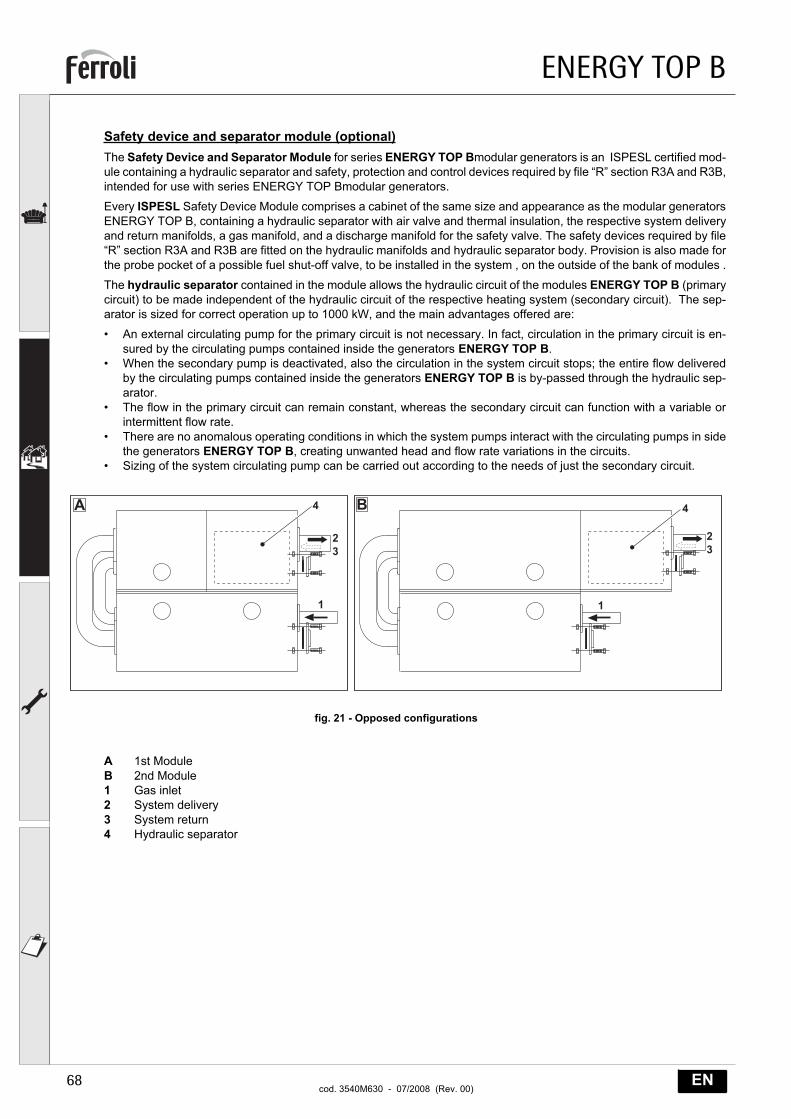
Safety device and separator module (optional)The Safety Device and Separator Module for series ENERGY TOP Bmodular generators is an ISPESL certified mod-ule containing a hydraulic separator and safety, protection and control devices required by file “R” section R3A and R3B,intended for use with series ENERGY TOP Bmodular generators.
Every ISPESL Safety Device Module comprises a cabinet of the same size and appearance as the modular generatorsENERGY TOP B, containing a hydraulic separator with air valve and thermal insulation, the respective system deliveryand return manifolds, a gas manifold, and a discharge manifold for the safety valve. The safety devices required by file“R” section R3A and R3B are fitted on the hydraulic manifolds and hydraulic separator body. Provision is also made forthe probe pocket of a possible fuel shut-off valve, to be installed in the system , on the outside of the bank of modules .
The hydraulic separator contained in the module allows the hydraulic circuit of the modules ENERGY TOP B (primarycircuit) to be made independent of the hydraulic circuit of the respective heating system (secondary circuit). The sep-arator is sized for correct operation up to 1000 kW, and the main advantages offered are:
• An external circulating pump for the primary circuit is not necessary. In fact, circulation in the primary circuit is en-sured by the circulating pumps contained inside the generators ENERGY TOP B.
• When the secondary pump is deactivated, also the circulation in the system circuit stops; the entire flow deliveredby the circulating pumps contained inside the generators ENERGY TOP B is by-passed through the hydraulic sep-arator.
• The flow in the primary circuit can remain constant, whereas the secondary circuit can function with a variable orintermittent flow rate.
• There are no anomalous operating conditions in which the system pumps interact with the circulating pumps in sidethe generators ENERGY TOP B, creating unwanted head and flow rate variations in the circuits.
• Sizing of the system circulating pump can be carried out according to the needs of just the secondary circuit.
fig. 21 - Opposed configurations
A 1st ModuleB 2nd Module1 Gas inlet2 System delivery3 System return4 Hydraulic separator
�� � �
� �
��
��
ENERGY TOP B
69ENcod. 3540M630 - 07/2008 (Rev. 00)
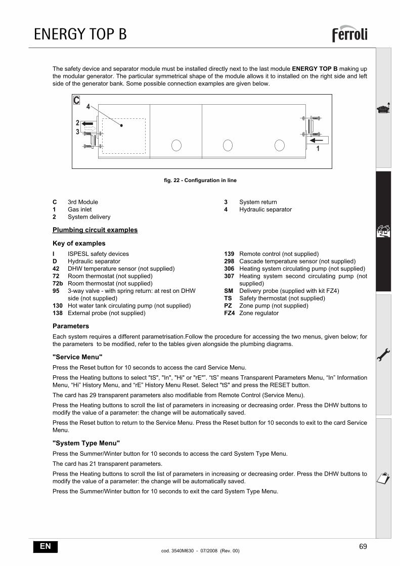
The safety device and separator module must be installed directly next to the last module ENERGY TOP B making upthe modular generator. The particular symmetrical shape of the module allows it to installed on the right side and leftside of the generator bank. Some possible connection examples are given below.
fig. 22 - Configuration in line
C 3rd Module1 Gas inlet2 System delivery
3 System return4 Hydraulic separator
Plumbing circuit examples
Key of examplesI ISPESL safety devicesD Hydraulic separator42 DHW temperature sensor (not supplied)72 Room thermostat (not supplied)72b Room thermostat (not supplied)95 3-way valve - with spring return: at rest on DHW
side (not supplied)130 Hot water tank circulating pump (not supplied)138 External probe (not supplied)
139 Remote control (not supplied)298 Cascade temperature sensor (not supplied)306 Heating system circulating pump (not supplied)307 Heating system second circulating pump (not
supplied)SM Delivery probe (supplied with kit FZ4)TS Safety thermostat (not supplied)PZ Zone pump (not supplied)FZ4 Zone regulator
ParametersEach system requires a different parametrisation.Follow the procedure for accessing the two menus, given below; forthe parameters to be modified, refer to the tables given alongside the plumbing diagrams.
"Service Menu"Press the Reset button for 10 seconds to access the card Service Menu.
Press the Heating buttons to select "tS", "In", "Hi" or "rE"”. “tS” means Transparent Parameters Menu, “In” InformationMenu, “Hi” History Menu, and “rE” History Menu Reset. Select "tS" and press the RESET button.
The card has 29 transparent parameters also modifiable from Remote Control (Service Menu).
Press the Heating buttons to scroll the list of parameters in increasing or decreasing order. Press the DHW buttons tomodify the value of a parameter: the change will be automatically saved.
Press the Reset button to return to the Service Menu. Press the Reset button for 10 seconds to exit to the card ServiceMenu.
"System Type Menu"Press the Summer/Winter button for 10 seconds to access the card System Type Menu.
The card has 21 transparent parameters.
Press the Heating buttons to scroll the list of parameters in increasing or decreasing order. Press the DHW buttons tomodify the value of a parameter: the change will be automatically saved.
Press the Summer/Winter button for 10 seconds to exit the card System Type Menu.
�
��
�
ENERGY TOP B
70 ENcod. 3540M630 - 07/2008 (Rev. 00)
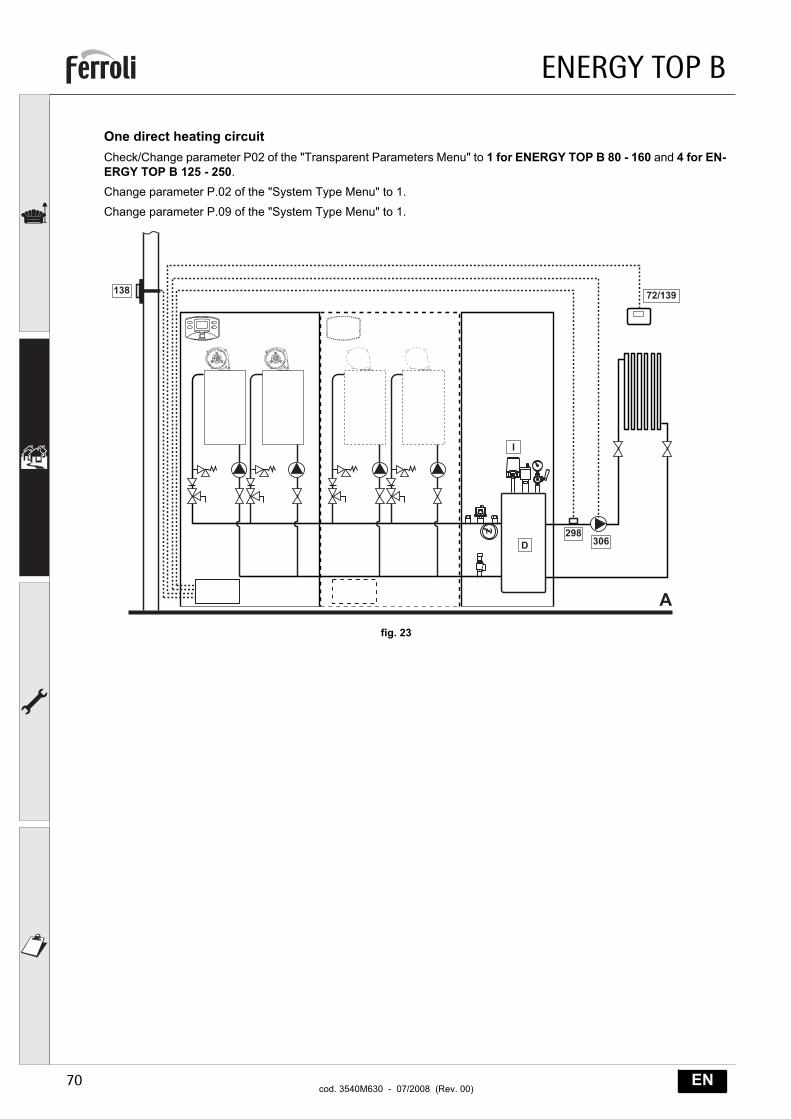
One direct heating circuitCheck/Change parameter P02 of the "Transparent Parameters Menu" to 1 for ENERGY TOP B 80 - 160 and 4 for EN-ERGY TOP B 125 - 250.
Change parameter P.02 of the "System Type Menu" to 1.
Change parameter P.09 of the "System Type Menu" to 1.
fig. 23
�
�
�
���
���
������
���
ENERGY TOP B
71ENcod. 3540M630 - 07/2008 (Rev. 00)
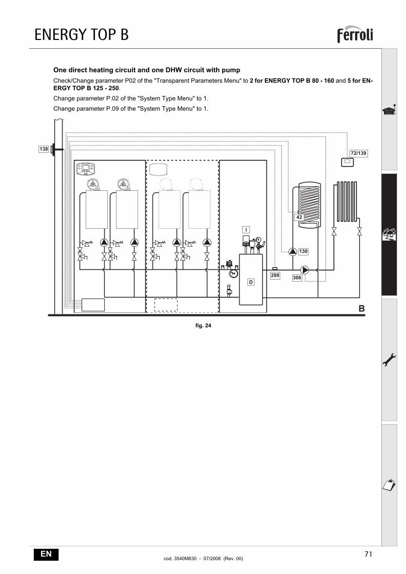
One direct heating circuit and one DHW circuit with pumpCheck/Change parameter P02 of the "Transparent Parameters Menu" to 2 for ENERGY TOP B 80 - 160 and 5 for EN-ERGY TOP B 125 - 250.
Change parameter P.02 of the "System Type Menu" to 1.
Change parameter P.09 of the "System Type Menu" to 1.
fig. 24
�
�
�
���
��� ���
��
���
������
ENERGY TOP B
72 ENcod. 3540M630 - 07/2008 (Rev. 00)
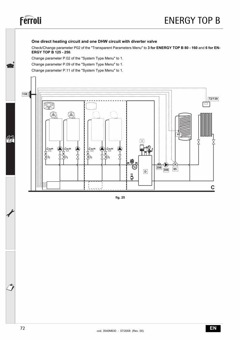
One direct heating circuit and one DHW circuit with diverter valveCheck/Change parameter P02 of the "Transparent Parameters Menu" to 3 for ENERGY TOP B 80 - 160 and 6 for EN-ERGY TOP B 125 - 250.
Change parameter P.02 of the "System Type Menu" to 1.
Change parameter P.09 of the "System Type Menu" to 1.
Change parameter P.11 of the "System Type Menu" to 1.
fig. 25
�
�
���
������ ��
��
������
ENERGY TOP B
73ENcod. 3540M630 - 07/2008 (Rev. 00)
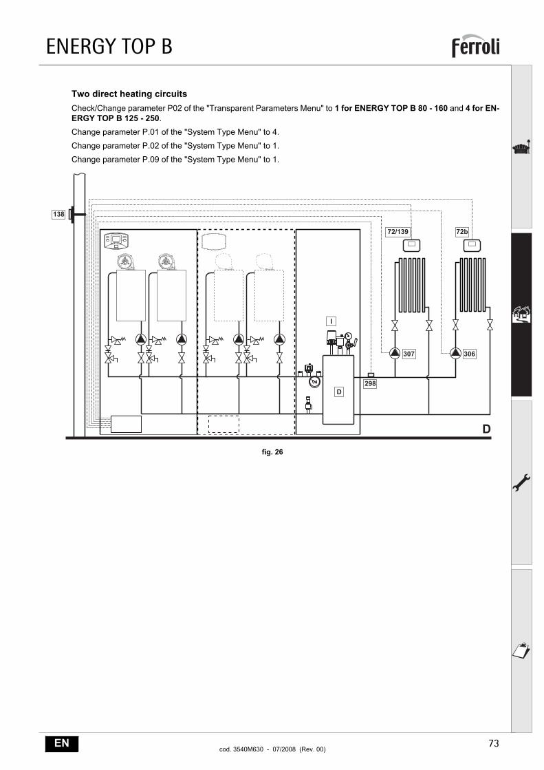
Two direct heating circuitsCheck/Change parameter P02 of the "Transparent Parameters Menu" to 1 for ENERGY TOP B 80 - 160 and 4 for EN-ERGY TOP B 125 - 250.
Change parameter P.01 of the "System Type Menu" to 4.
Change parameter P.02 of the "System Type Menu" to 1.
Change parameter P.09 of the "System Type Menu" to 1.
fig. 26
�
�
�
���
��� ���
���
���������
ENERGY TOP B
74 ENcod. 3540M630 - 07/2008 (Rev. 00)
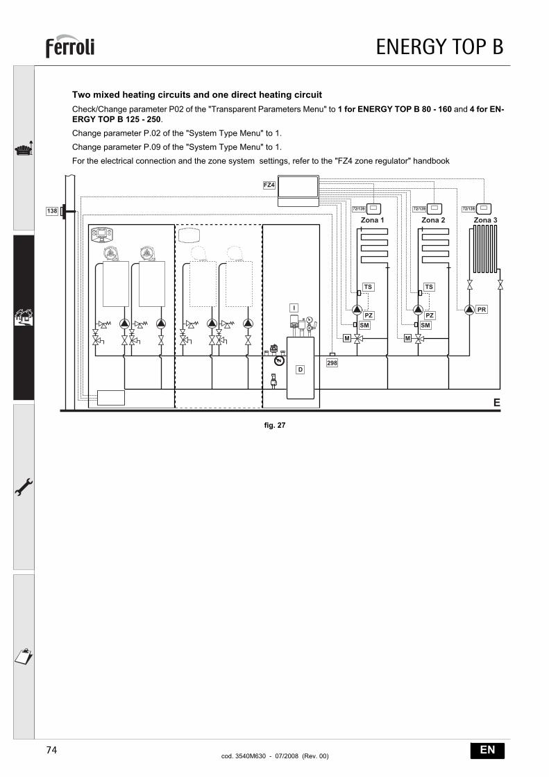
Two mixed heating circuits and one direct heating circuitCheck/Change parameter P02 of the "Transparent Parameters Menu" to 1 for ENERGY TOP B 80 - 160 and 4 for EN-ERGY TOP B 125 - 250.
Change parameter P.02 of the "System Type Menu" to 1.
Change parameter P.09 of the "System Type Menu" to 1.
For the electrical connection and the zone system settings, refer to the "FZ4 zone regulator" handbook
fig. 27
�
���� � ���� � ���� �
! !
�
�
"!
���
���
#�
$"
"!
#�
$"
#%
&��
������ ������ ������
ENERGY TOP B
75ENcod. 3540M630 - 07/2008 (Rev. 00)
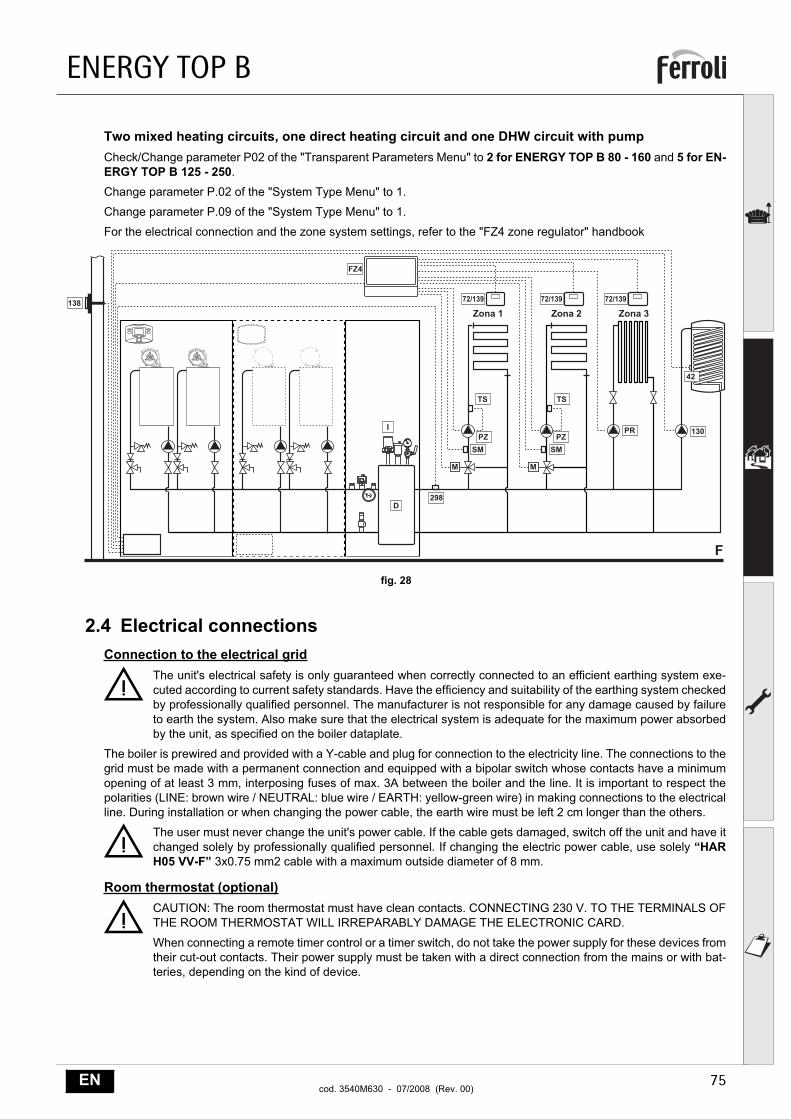
Two mixed heating circuits, one direct heating circuit and one DHW circuit with pumpCheck/Change parameter P02 of the "Transparent Parameters Menu" to 2 for ENERGY TOP B 80 - 160 and 5 for EN-ERGY TOP B 125 - 250.
Change parameter P.02 of the "System Type Menu" to 1.
Change parameter P.09 of the "System Type Menu" to 1.
For the electrical connection and the zone system settings, refer to the "FZ4 zone regulator" handbook
fig. 28
2.4 Electrical connectionsConnection to the electrical grid
BThe unit's electrical safety is only guaranteed when correctly connected to an efficient earthing system exe-cuted according to current safety standards. Have the efficiency and suitability of the earthing system checkedby professionally qualified personnel. The manufacturer is not responsible for any damage caused by failureto earth the system. Also make sure that the electrical system is adequate for the maximum power absorbedby the unit, as specified on the boiler dataplate.
The boiler is prewired and provided with a Y-cable and plug for connection to the electricity line. The connections to thegrid must be made with a permanent connection and equipped with a bipolar switch whose contacts have a minimumopening of at least 3 mm, interposing fuses of max. 3A between the boiler and the line. It is important to respect thepolarities (LINE: brown wire / NEUTRAL: blue wire / EARTH: yellow-green wire) in making connections to the electricalline. During installation or when changing the power cable, the earth wire must be left 2 cm longer than the others.
BThe user must never change the unit's power cable. If the cable gets damaged, switch off the unit and have itchanged solely by professionally qualified personnel. If changing the electric power cable, use solely “HARH05 VV-F” 3x0.75 mm2 cable with a maximum outside diameter of 8 mm.
Room thermostat (optional)
BCAUTION: The room thermostat must have clean contacts. CONNECTING 230 V. TO THE TERMINALS OFTHE ROOM THERMOSTAT WILL IRREPARABLY DAMAGE THE ELECTRONIC CARD.
When connecting a remote timer control or a timer switch, do not take the power supply for these devices fromtheir cut-out contacts. Their power supply must be taken with a direct connection from the mains or with bat-teries, depending on the kind of device.
&
���� � ���� � ���� �
! !
�
�
"!
���
"!
#%#�
���
��
���
#�
$" $"
������
&��
������ ������
ENERGY TOP B
76 ENcod. 3540M630 - 07/2008 (Rev. 00)
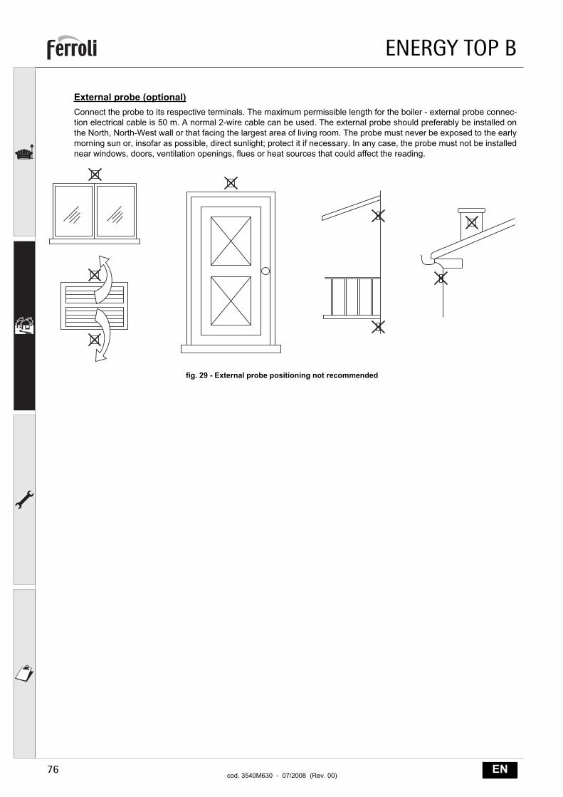
External probe (optional)Connect the probe to its respective terminals. The maximum permissible length for the boiler - external probe connec-tion electrical cable is 50 m. A normal 2-wire cable can be used. The external probe should preferably be installed onthe North, North-West wall or that facing the largest area of living room. The probe must never be exposed to the earlymorning sun or, insofar as possible, direct sunlight; protect it if necessary. In any case, the probe must not be installednear windows, doors, ventilation openings, flues or heat sources that could affect the reading.
fig. 29 - External probe positioning not recommended
ENERGY TOP B
77ENcod. 3540M630 - 07/2008 (Rev. 00)
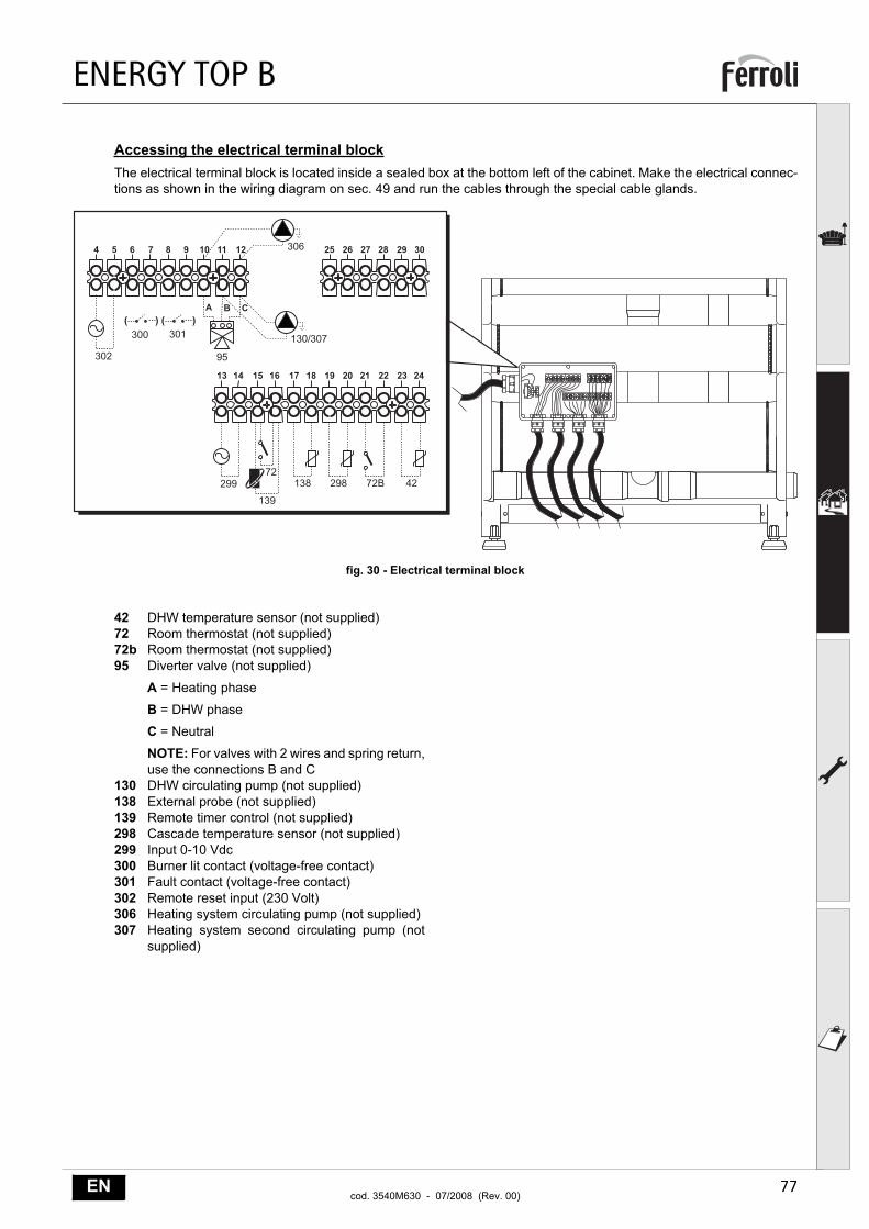
Accessing the electrical terminal blockThe electrical terminal block is located inside a sealed box at the bottom left of the cabinet. Make the electrical connec-tions as shown in the wiring diagram on sec. 49 and run the cables through the special cable glands.
fig. 30 - Electrical terminal block
42 DHW temperature sensor (not supplied)72 Room thermostat (not supplied)72b Room thermostat (not supplied)95 Diverter valve (not supplied)
A = Heating phase
B = DHW phase
C = Neutral
NOTE: For valves with 2 wires and spring return,use the connections B and C
130 DHW circulating pump (not supplied)138 External probe (not supplied)139 Remote timer control (not supplied)298 Cascade temperature sensor (not supplied)299 Input 0-10 Vdc300 Burner lit contact (voltage-free contact)301 Fault contact (voltage-free contact)302 Remote reset input (230 Volt)306 Heating system circulating pump (not supplied)307 Heating system second circulating pump (not
supplied)
� � � � � � �� �� ��
�� �� �� �� �� �� �� �� �� �� �� ��
' '' '��� ���
����
�
��
����� �� ��
�� �� �� �� �� ��
���
�������
��
� �
ENERGY TOP B
78 ENcod. 3540M630 - 07/2008 (Rev. 00)
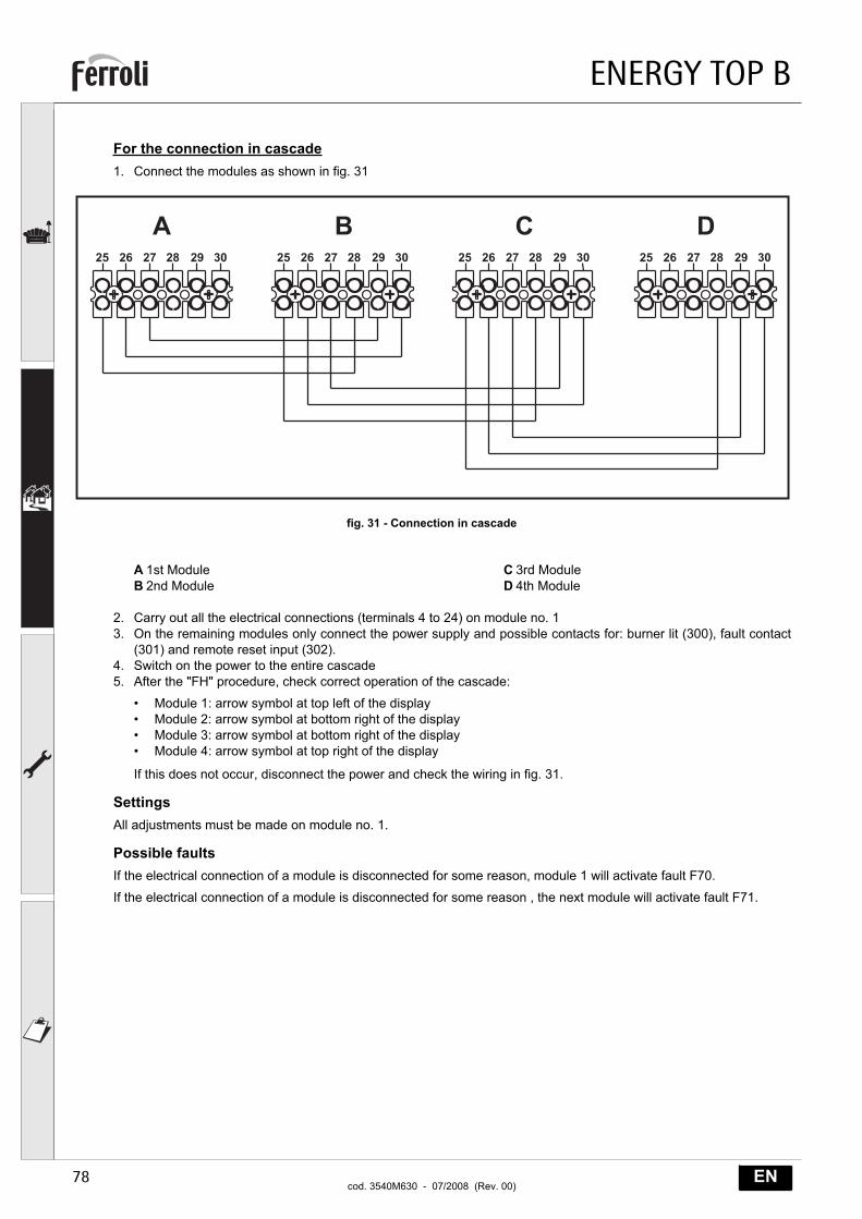
For the connection in cascade1. Connect the modules as shown in fig. 31
fig. 31 - Connection in cascade
A 1st ModuleB 2nd Module
C 3rd ModuleD 4th Module
2. Carry out all the electrical connections (terminals 4 to 24) on module no. 13. On the remaining modules only connect the power supply and possible contacts for: burner lit (300), fault contact
(301) and remote reset input (302).4. Switch on the power to the entire cascade5. After the "FH" procedure, check correct operation of the cascade:
• Module 1: arrow symbol at top left of the display• Module 2: arrow symbol at bottom right of the display• Module 3: arrow symbol at bottom right of the display• Module 4: arrow symbol at top right of the display
If this does not occur, disconnect the power and check the wiring in fig. 31.
SettingsAll adjustments must be made on module no. 1.
Possible faultsIf the electrical connection of a module is disconnected for some reason, module 1 will activate fault F70.
If the electrical connection of a module is disconnected for some reason , the next module will activate fault F71.
�� �� �� �� �� �� �� �� �� �� �� �� �� �� �� �� �� �� �� �� �� �� �� ��
� � �
ENERGY TOP B
79ENcod. 3540M630 - 07/2008 (Rev. 00)
2.5 Flue connectionImportantThe unit is a B23 type with combustion air drawn from the installation room and fume exhaust by means of a fan (oper-ation with flue under pressure) and must be connected to one of the discharge systems indicated below. Before pro-ceeding with installation, check and carefully comply with the local regulations and provisions. Also comply with theprovisions concerning the positioning of wall and/or roof terminals and the minimum distances from windows, walls, ven-tilation openings, etc.
Manifold, ducts and flue must be suitably sized, designed and made in compliance with the current standards. Theymust be made of suitable materials, i.e. resistant to heat and corrosion, smooth on the inside and hermetic. In particular,joints must be condensate-proof. Also provide for suitable condensate drainage points, connected through a trap to pre-vent the condensate produced in the flues from running into the generators.
BThe unit is equipped with one (models ENERGY TOP B 80 - 125) or two (models ENERGY TOP B 160 - 250)separate Ø80 flue connections for the two burner - exchanger units.
The combustion circuits of the two units are completely independent. When joining the two fume outlets to asingle flue or manifold (in case of a single module or connection in cascade) it is necessary to install a fumeanti-backflow valveon each outlet to prevent operation anomalies or the creation of hazardous conditions.Make sure to use the optional FERROLIkits , provided with special anti-backflow valves.
ABefore carrying out the flue connection, make sure to fill the condensate trap with approx. 0.5 litres of waterthrough the flue connections.
Connection with separate pipesSeparate Ø80 ducts can be connected directly to the unit. Insert the seal 1KWMA84A on the Ø80 pipes leaving the unitand make it adhere to the upper wall of the cabinet.
Before proceeding with installation, make sure the maximum permissible length has not been exceeded, by means ofa simple calculation:
1. Establish the layout of the system of split flues, including accessories and outlet terminals for each of the two burner/exchanger bodies.
2. Consult the table 5 and identify the losses in meq (equivalent metres) of every component, according to the instal-lation position.
3. Check that the sum total of losses is less than or equal to the maximum permissible length in table 4.
Table. 4 - Max. length separate ducts
Table. 5 - Accessories
Separate ducts
For each single Exchanger/Burner Body
Max. permissible length 20 meq
Losses in meq
Fume exhaust
Vertical Horizontal
Ø 80 PIPE 1 m M/F 1KWMA83W 1.6 2.0
BEND 45° M/F 1KWMA65W 1.8
90° M/F 1KWMA01W 2.0
PIPE SECTION with test point 1KWMA70W 0.3
TERMINAL fumes, wall with antiwind 1KWMA86A 5.0
FLUE Split air/fumes 80/80 1KWMA84U 5.0
ENERGY TOP B
80 ENcod. 3540M630 - 07/2008 (Rev. 00)
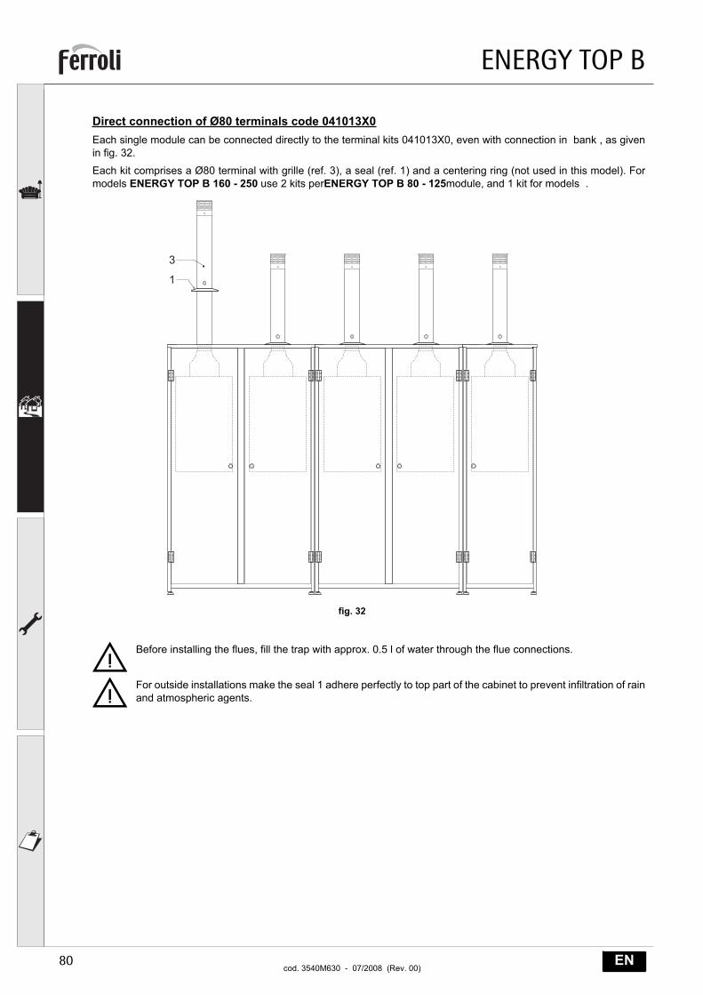
Direct connection of Ø80 terminals code 041013X0Each single module can be connected directly to the terminal kits 041013X0, even with connection in bank , as givenin fig. 32.
Each kit comprises a Ø80 terminal with grille (ref. 3), a seal (ref. 1) and a centering ring (not used in this model). Formodels ENERGY TOP B 160 - 250 use 2 kits perENERGY TOP B 80 - 125module, and 1 kit for models .
fig. 32
BBefore installing the flues, fill the trap with approx. 0.5 l of water through the flue connections.
BFor outside installations make the seal 1 adhere perfectly to top part of the cabinet to prevent infiltration of rainand atmospheric agents.
�
�
ENERGY TOP B
81ENcod. 3540M630 - 07/2008 (Rev. 00)
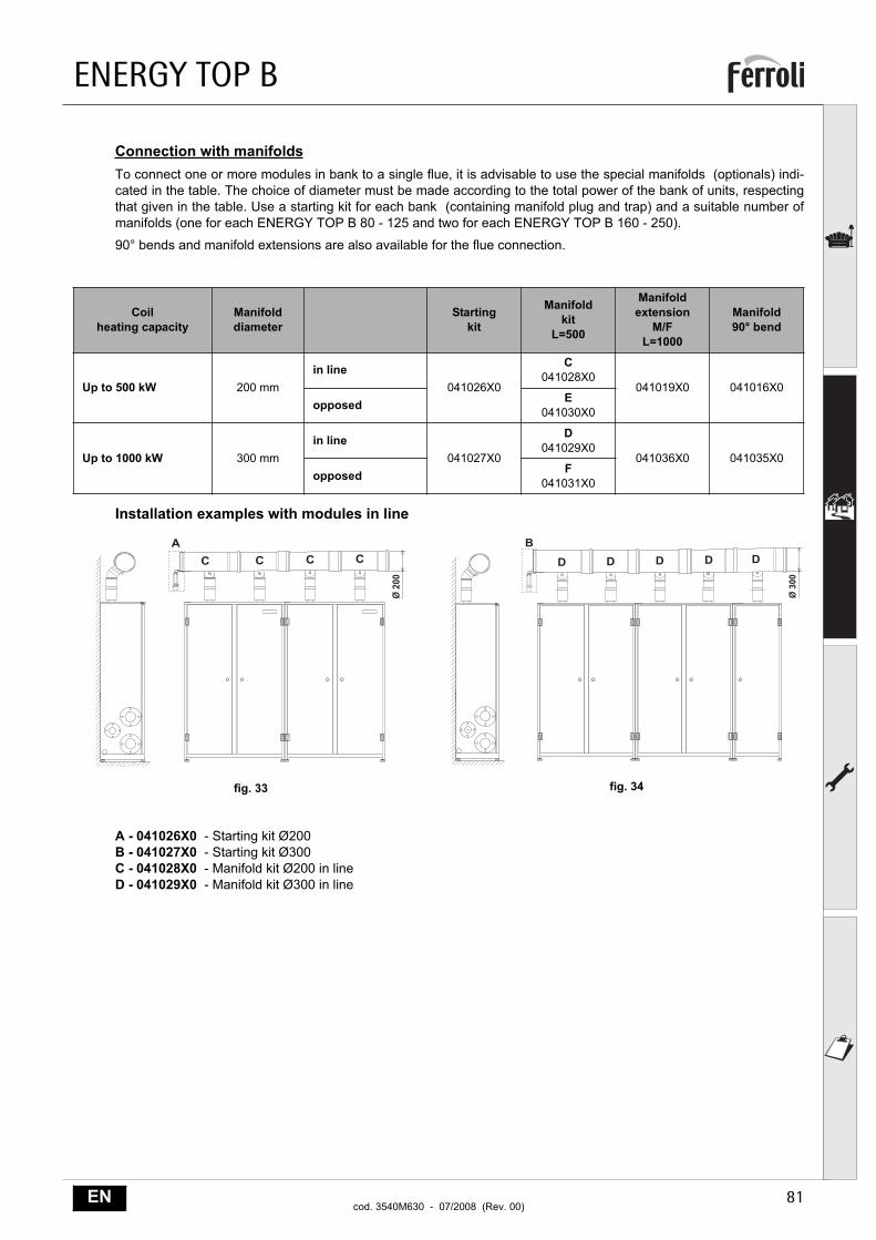
Connection with manifoldsTo connect one or more modules in bank to a single flue, it is advisable to use the special manifolds (optionals) indi-cated in the table. The choice of diameter must be made according to the total power of the bank of units, respectingthat given in the table. Use a starting kit for each bank (containing manifold plug and trap) and a suitable number ofmanifolds (one for each ENERGY TOP B 80 - 125 and two for each ENERGY TOP B 160 - 250).
90° bends and manifold extensions are also available for the flue connection.
Installation examples with modules in line
fig. 33 fig. 34
A - 041026X0 - Starting kit Ø200B - 041027X0 - Starting kit Ø300C - 041028X0 - Manifold kit Ø200 in lineD - 041029X0 - Manifold kit Ø300 in line
Coilheating capacity
Manifolddiameter
Startingkit
Manifoldkit
L=500
Manifoldextension
M/FL=1000
Manifold90° bend
Up to 500 kW 200 mmin line
041026X0
C041028X0
041019X0 041016X0opposed E
041030X0
Up to 1000 kW 300 mmin line
041027X0
D041029X0
041036X0 041035X0opposed F
041031X0
( �
��
�
( �
��
�
�
� � � �
ENERGY TOP B
82 ENcod. 3540M630 - 07/2008 (Rev. 00)
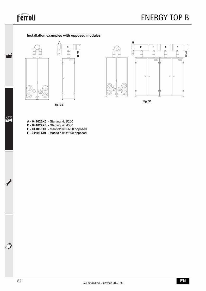
Installation examples with opposed modules
fig. 35fig. 36
A - 041026X0 - Starting kit Ø200B - 041027X0 - Starting kit Ø300E - 041030X0 - Manifold kit Ø200 opposedF - 041031X0 - Manifold kit Ø300 opposed
�
( �
��
�
( �
��
&
�
& & &
ENERGY TOP B
83ENcod. 3540M630 - 07/2008 (Rev. 00)
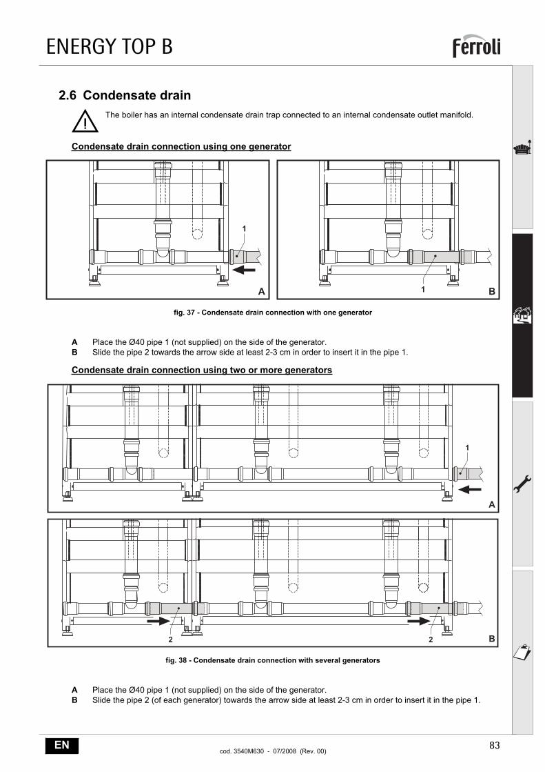
2.6 Condensate drain
BThe boiler has an internal condensate drain trap connected to an internal condensate outlet manifold.
Condensate drain connection using one generator
fig. 37 - Condensate drain connection with one generator
A Place the Ø40 pipe 1 (not supplied) on the side of the generator.B Slide the pipe 2 towards the arrow side at least 2-3 cm in order to insert it in the pipe 1.
Condensate drain connection using two or more generators
fig. 38 - Condensate drain connection with several generators
A Place the Ø40 pipe 1 (not supplied) on the side of the generator.B Slide the pipe 2 (of each generator) towards the arrow side at least 2-3 cm in order to insert it in the pipe 1.
�
� � �
��
�
�
�
ENERGY TOP B
84 ENcod. 3540M630 - 07/2008 (Rev. 00)
3. Service and maintenanceAll adjustment, conversion, start-up and maintenance operations described below must only be carried out by Qualified Per-sonnel (meeting the professional technical requirements prescribed by current regulations) such as those of the Local After-Sales Technical Service.
FERROLI declines any liability for damage and/or injury caused by unqualified and unauthorised persons tampering withthe unit.
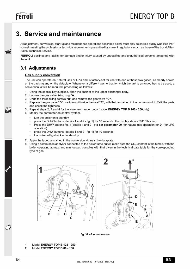
3.1 AdjustmentsGas supply conversionThe unit can operate on Natural Gas or LPG and is factory-set for use with one of these two gases, as clearly shownon the packing and on the dataplate. Whenever a different gas to that for which the unit is arranged has to be used, aconversion kit will be required, proceeding as follows:
1. Using the special key supplied, open the cabinet of the upper exchanger body.2. Loosen the gas valve fixing ring “A.3. Undo the three fixing screws “B” and remove the gas valve “C“.4. Replace the gas valve “D” positioning it inside the seal “E”, with that contained in the conversion kit. Refit the parts
and check the tightness.5. Repeat steps 2, 3 and 4 for the lower exchanger body (model ENERGY TOP B 160 - 250only)6. Modify the parameter on control system.
• turn the boiler onto standby• press the DHW buttons (details 1 and 2 - fig. 1) for 10 seconds: the display shows “P01“ flashing.• Press the DHW buttons fig. 1 (details 1 and 2 - ) to set parameter 00 (for natural gas operation) or 01 (for LPG
operation).• press the DHW buttons (details 1 and 2 - fig. 1) for 10 seconds.• the boiler will go back onto standby
7. Apply the label, contained in the conversion kit, near the dataplate.8. Using a combustion analyser connected to the boiler fume outlet, make sure the CO2 content in the fumes, with the
boiler operating at max. and min. output, complies with that given in the technical data table for the correspondingtype of gas.
fig. 39 - Gas conversion
1 Model ENERGY TOP B 125 - 2502 Model ENERGY TOP B 80 - 160
�
�
�
�
� � �
�
��
ENERGY TOP B
85ENcod. 3540M630 - 07/2008 (Rev. 00)
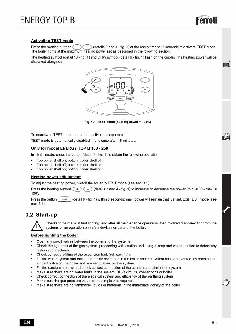
Activating TEST modePress the heating buttons (details 3 and 4 - fig. 1) at the same time for 5 seconds to activate TEST mode.The boiler lights at the maximum heating power set as described in the following section.
The heating symbol (detail 13 - fig. 1) and DHW symbol (detail 9 - fig. 1) flash on the display; the heating power will bedisplayed alongside.
fig. 40 - TEST mode (heating power = 100%)
To deactivate TEST mode, repeat the activation sequence.
TEST mode is automatically disabled in any case after 15 minutes.
Only for model ENERGY TOP B 160 - 250In TEST mode, press the button (detail 7 - fig. 1) to obtain the following operation:
• Top boiler shell on; bottom boiler shell off.• Top boiler shell off; bottom boiler shell on.• Top boiler shell on; bottom boiler shell on.
Heating power adjustmentTo adjust the heating power, switch the boiler to TEST mode (see sec. 3.1).
Press the heating buttons (details 3 and 4 - fig. 1) to increase or decrease the power (min. = 00 - max. =100).
Press the button (detail 8 - fig. 1) within 5 seconds; max. power will remain that just set. Exit TEST mode (seesec. 3.1).
3.2 Start-up
BChecks to be made at first lighting, and after all maintenance operations that involved disconnection from thesystems or an operation on safety devices or parts of the boiler:
Before lighting the boiler• Open any on-off valves between the boiler and the systems.• Check the tightness of the gas system, proceeding with caution and using a soap and water solution to detect any
leaks in connections.• Check correct prefilling of the expansion tank (ref. sec. 4.4).• Fill the water system and make sure all air contained in the boiler and the system has been vented, by opening the
air vent valve on the boiler and any vent valves on the system. • Fill the condensate trap and check correct connection of the condensate elimination system.• Make sure there are no water leaks in the system, DHW circuits, connections or boiler.• Check correct connection of the electrical system and efficiency of the earthing system• Make sure the gas pressure value for heating is that required.• Make sure there are no flammable liquids or materials in the immediate vicinity of the boiler
����� ���������
��������������������� �����������������������
�����
ENERGY TOP B
86 ENcod. 3540M630 - 07/2008 (Rev. 00)
Checks during operation• Turn the unit on as described in sec. 1.3.• Make sure the fuel circuit and water systems are tight.• Check the efficiency of the flue and air-fume ducts while the boiler is working.• Check the correct tightness and functionality of the condensate elimination system and trap.• Make sure the water is circulating properly between the boiler and the systems.• Make sure the gas valve modulates correctly in the heating and domestic hot water production phases.• Check proper boiler lighting by doing several tests, turning it on and off with the room thermostat or remote control.• Using a combustion analyser connected to the boiler fume outlet, check that the CO2 content in the fumes, with the
boiler operating at max. and min. output, corresponds to that given in the technical data table for the correspondingtype of gas.
• Make sure the fuel consumption indicated on the meter matches that given in the technical data table on sec. 4.4.• Check the correct programming of the parameters and carry out any necessary customization (compensation curve,
power, temperatures, etc.).
3.3 MaintenancePeriodical checkTo keep the unit working properly over time, it is necessary to have qualified personnel make an annual check that in-cludes the following tests:
• The control and safety devices (gas valve, flow meter, thermostats, etc.) must function correctly.• The fume extraction circuit must be fully efficient.• The airtight chamber must be sealed• The air-fume end piece and ducts must be free of obstructions and leaks• The condensate evacuation system must be efficient with no leakage or obstructions.• The burner and exchanger must be clean and free of scale. When cleaning, do not use chemical products or wire
brushes.• The electrode must be free of scale and properly positioned.• The gas and water systems must be airtight.• The water pressure in the cold water system must be about 1 bar; otherwise, bring it to that value.• The circulation pump must not be blocked.• The expansion tank must be filled.• The gas flow and pressure must correspond to that given in the respective tables.
AThe boiler casing, panel and aesthetic parts can be cleaned with a soft damp cloth, possibly soaked in soapywater. Do not use any abrasive detergents and solvents.
ENERGY TOP B
87ENcod. 3540M630 - 07/2008 (Rev. 00)
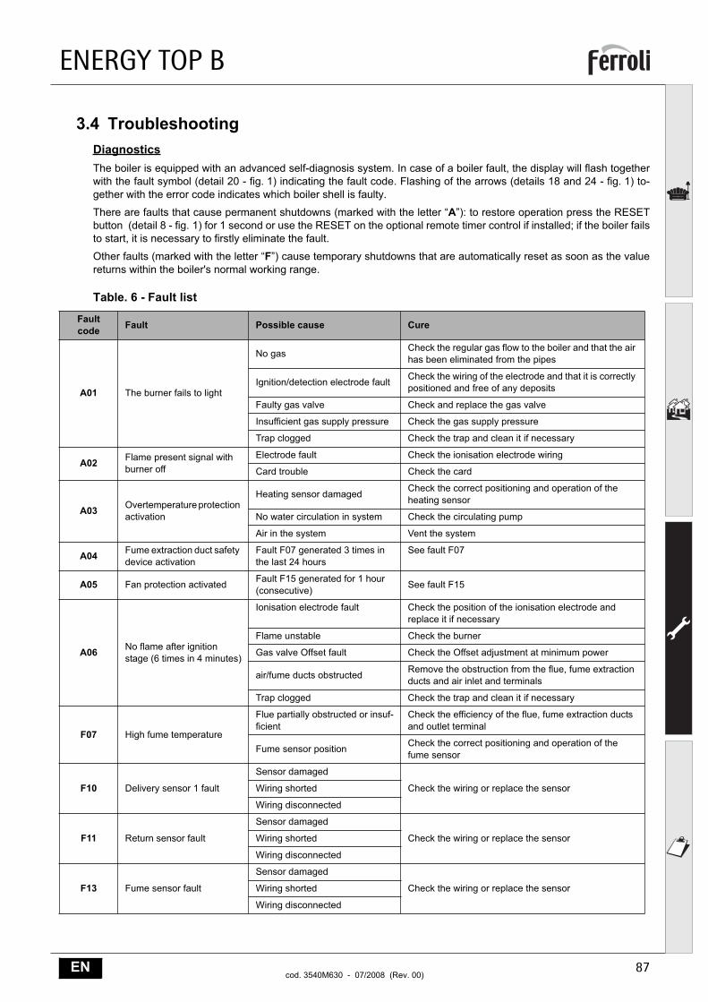
3.4 TroubleshootingDiagnosticsThe boiler is equipped with an advanced self-diagnosis system. In case of a boiler fault, the display will flash togetherwith the fault symbol (detail 20 - fig. 1) indicating the fault code. Flashing of the arrows (details 18 and 24 - fig. 1) to-gether with the error code indicates which boiler shell is faulty.
There are faults that cause permanent shutdowns (marked with the letter “A”): to restore operation press the RESETbutton (detail 8 - fig. 1) for 1 second or use the RESET on the optional remote timer control if installed; if the boiler failsto start, it is necessary to firstly eliminate the fault.
Other faults (marked with the letter “F”) cause temporary shutdowns that are automatically reset as soon as the valuereturns within the boiler's normal working range.
Table. 6 - Fault list
Fault code Fault Possible cause Cure
A01 The burner fails to light
No gas Check the regular gas flow to the boiler and that the air has been eliminated from the pipes
Ignition/detection electrode fault Check the wiring of the electrode and that it is correctly positioned and free of any deposits
Faulty gas valve Check and replace the gas valve
Insufficient gas supply pressure Check the gas supply pressure
Trap clogged Check the trap and clean it if necessary
A02 Flame present signal with burner off
Electrode fault Check the ionisation electrode wiring
Card trouble Check the card
A03 Overtemperature protection activation
Heating sensor damaged Check the correct positioning and operation of the heating sensor
No water circulation in system Check the circulating pump
Air in the system Vent the system
A04 Fume extraction duct safety device activation
Fault F07 generated 3 times in the last 24 hours
See fault F07
A05 Fan protection activated Fault F15 generated for 1 hour (consecutive) See fault F15
A06 No flame after ignition stage (6 times in 4 minutes)
Ionisation electrode fault Check the position of the ionisation electrode and replace it if necessary
Flame unstable Check the burner
Gas valve Offset fault Check the Offset adjustment at minimum power
air/fume ducts obstructed Remove the obstruction from the flue, fume extraction ducts and air inlet and terminals
Trap clogged Check the trap and clean it if necessary
F07 High fume temperature
Flue partially obstructed or insuf-ficient
Check the efficiency of the flue, fume extraction ducts and outlet terminal
Fume sensor position Check the correct positioning and operation of the fume sensor
F10 Delivery sensor 1 fault
Sensor damaged
Check the wiring or replace the sensorWiring shorted
Wiring disconnected
F11 Return sensor fault
Sensor damaged
Check the wiring or replace the sensorWiring shorted
Wiring disconnected
F13 Fume sensor fault
Sensor damaged
Check the wiring or replace the sensorWiring shorted
Wiring disconnected
ENERGY TOP B
88 ENcod. 3540M630 - 07/2008 (Rev. 00)
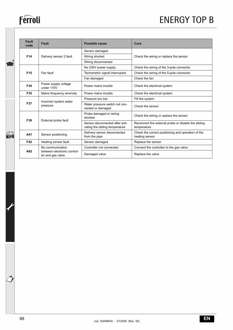
F14 Delivery sensor 2 fault
Sensor damaged
Check the wiring or replace the sensorWiring shorted
Wiring disconnected
F15 Fan fault
No 230V power supply Check the wiring of the 3-pole connector
Tachometric signal interrupted Check the wiring of the 5-pole connector
Fan damaged Check the fan
F34 Power supply voltage under 170V Power mains trouble Check the electrical system
F35 Mains frequency anomaly Power mains trouble Check the electrical system
F37 Incorrect system water pressure
Pressure too low Fill the system
Water pressure switch not con-nected or damaged Check the sensor
F39 External probe fault
Probe damaged or wiring shorted Check the wiring or replace the sensor
Sensor disconnected after acti-vating the sliding temperature
Reconnect the external probe or disable the sliding temperature
A41 Sensor positioning Delivery sensor disconnected from the pipe
Check the correct positioning and operation of the heating sensor
F42 Heating sensor fault Sensor damaged Replace the sensor
A62No communication between electronic control-ler and gas valve
Controller not connected Connect the controller to the gas valve
Damaged valve Replace the valve
Fault code Fault Possible cause Cure
ENERGY TOP B
89ENcod. 3540M630 - 07/2008 (Rev. 00)
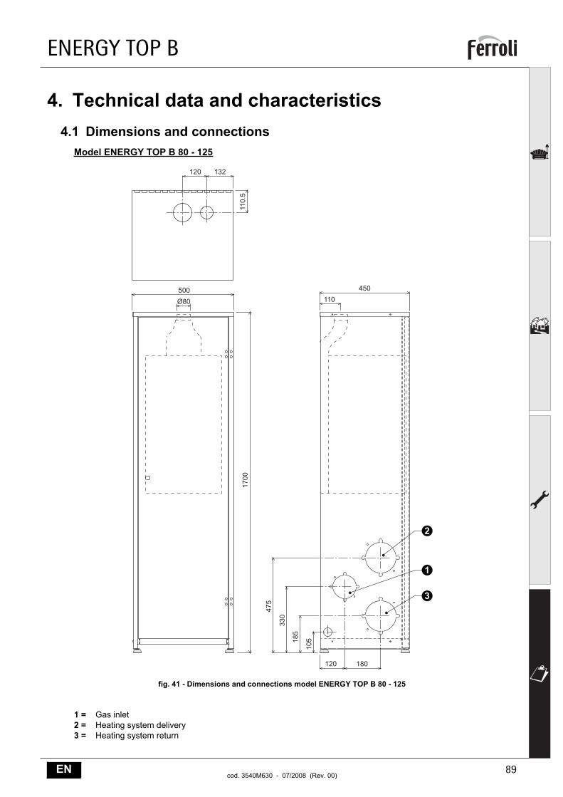
4. Technical data and characteristics4.1 Dimensions and connections
Model ENERGY TOP B 80 - 125
fig. 41 - Dimensions and connections model ENERGY TOP B 80 - 125
1 = Gas inlet2 = Heating system delivery3 = Heating system return
��� ���
����
�
���
��� ���
���
����
���
���
���
���
��� ���
�
�
�
ENERGY TOP B
90 ENcod. 3540M630 - 07/2008 (Rev. 00)
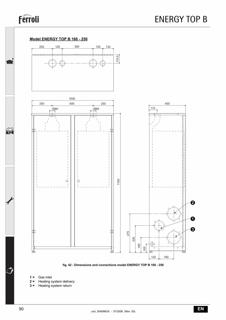
Model ENERGY TOP B 160 - 250
fig. 42 - Dimensions and connections model ENERGY TOP B 160 - 250
1 = Gas inlet2 = Heating system delivery3 = Heating system return
���
����
���
���
����
���
���
���
���
��� ���
�
�
�
���
��� ������
��� ���
����
�
��� ������
ENERGY TOP B
91ENcod. 3540M630 - 07/2008 (Rev. 00)
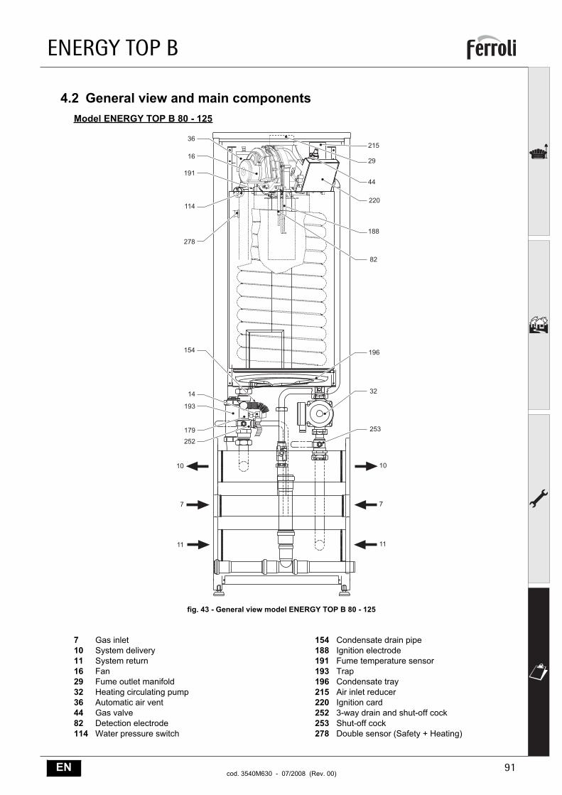
4.2 General view and main componentsModel ENERGY TOP B 80 - 125
fig. 43 - General view model ENERGY TOP B 80 - 125
7 Gas inlet10 System delivery11 System return16 Fan29 Fume outlet manifold32 Heating circulating pump36 Automatic air vent44 Gas valve82 Detection electrode114 Water pressure switch
154 Condensate drain pipe 188 Ignition electrode191 Fume temperature sensor193 Trap196 Condensate tray 215 Air inlet reducer220 Ignition card252 3-way drain and shut-off cock 253 Shut-off cock 278 Double sensor (Safety + Heating)
��
�
��
��
�
��
��
��
�
��
���
���
��
�
����
�
��
���
���
���
���
���
��
��
ENERGY TOP B
92 ENcod. 3540M630 - 07/2008 (Rev. 00)
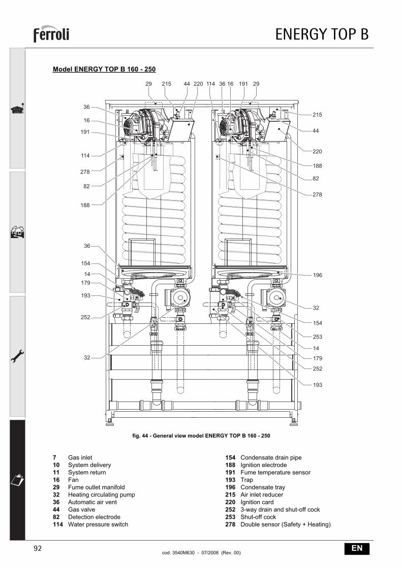
Model ENERGY TOP B 160 - 250
fig. 44 - General view model ENERGY TOP B 160 - 250
7 Gas inlet10 System delivery11 System return16 Fan29 Fume outlet manifold32 Heating circulating pump36 Automatic air vent44 Gas valve82 Detection electrode114 Water pressure switch
154 Condensate drain pipe 188 Ignition electrode191 Fume temperature sensor193 Trap196 Condensate tray 215 Air inlet reducer220 Ignition card252 3-way drain and shut-off cock 253 Shut-off cock 278 Double sensor (Safety + Heating)
�
�
��
���
���
��
���
� ��� �� ��� ��� � � �� �
���
��
���
�
��
���
���
���
��
�
���
��
���
��
���
��
���
��
��
��
��
ENERGY TOP B
93ENcod. 3540M630 - 07/2008 (Rev. 00)
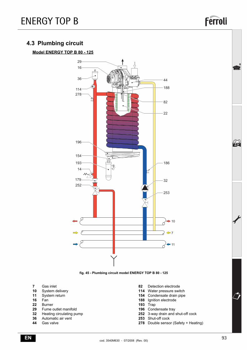
4.3 Plumbing circuitModel ENERGY TOP B 80 - 125
fig. 45 - Plumbing circuit model ENERGY TOP B 80 - 125
7 Gas inlet10 System delivery11 System return16 Fan22 Burner29 Fume outlet manifold32 Heating circulating pump36 Automatic air vent44 Gas valve
82 Detection electrode114 Water pressure switch154 Condensate drain pipe 188 Ignition electrode193 Trap196 Condensate tray 252 3-way drain and shut-off cock 253 Shut-off cock 278 Double sensor (Safety + Heating)
�
�
���
��
���
��
�
�
���
��
��
���
��
���
���
��
��
��
��
��
�
ENERGY TOP B
94 ENcod. 3540M630 - 07/2008 (Rev. 00)
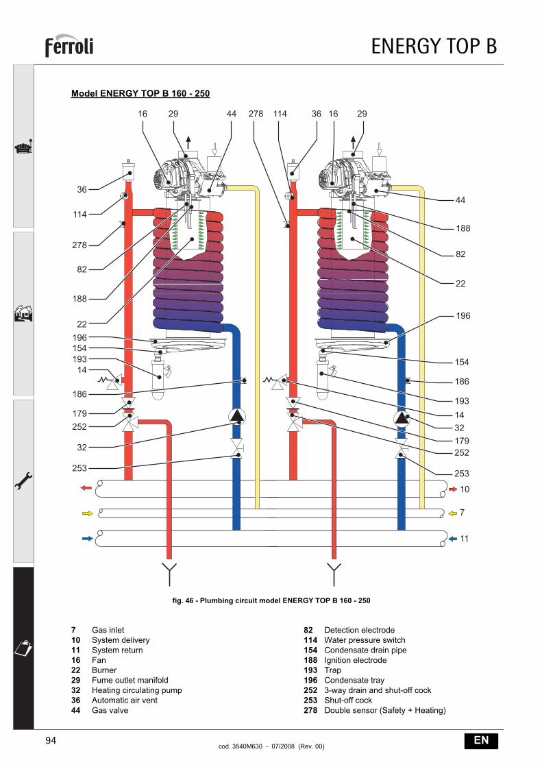
Model ENERGY TOP B 160 - 250
fig. 46 - Plumbing circuit model ENERGY TOP B 160 - 250
7 Gas inlet10 System delivery11 System return16 Fan22 Burner29 Fume outlet manifold32 Heating circulating pump36 Automatic air vent44 Gas valve
82 Detection electrode114 Water pressure switch154 Condensate drain pipe 188 Ignition electrode193 Trap196 Condensate tray 252 3-way drain and shut-off cock 253 Shut-off cock 278 Double sensor (Safety + Heating)
��
���
��
��
�
���
��
��
��
���
���
��
�
��
� � �� ��� ��� � � �
�
���
���
��
���
��
������
��
���
��
���
��
��
��
��
ENERGY TOP B
95ENcod. 3540M630 - 07/2008 (Rev. 00)
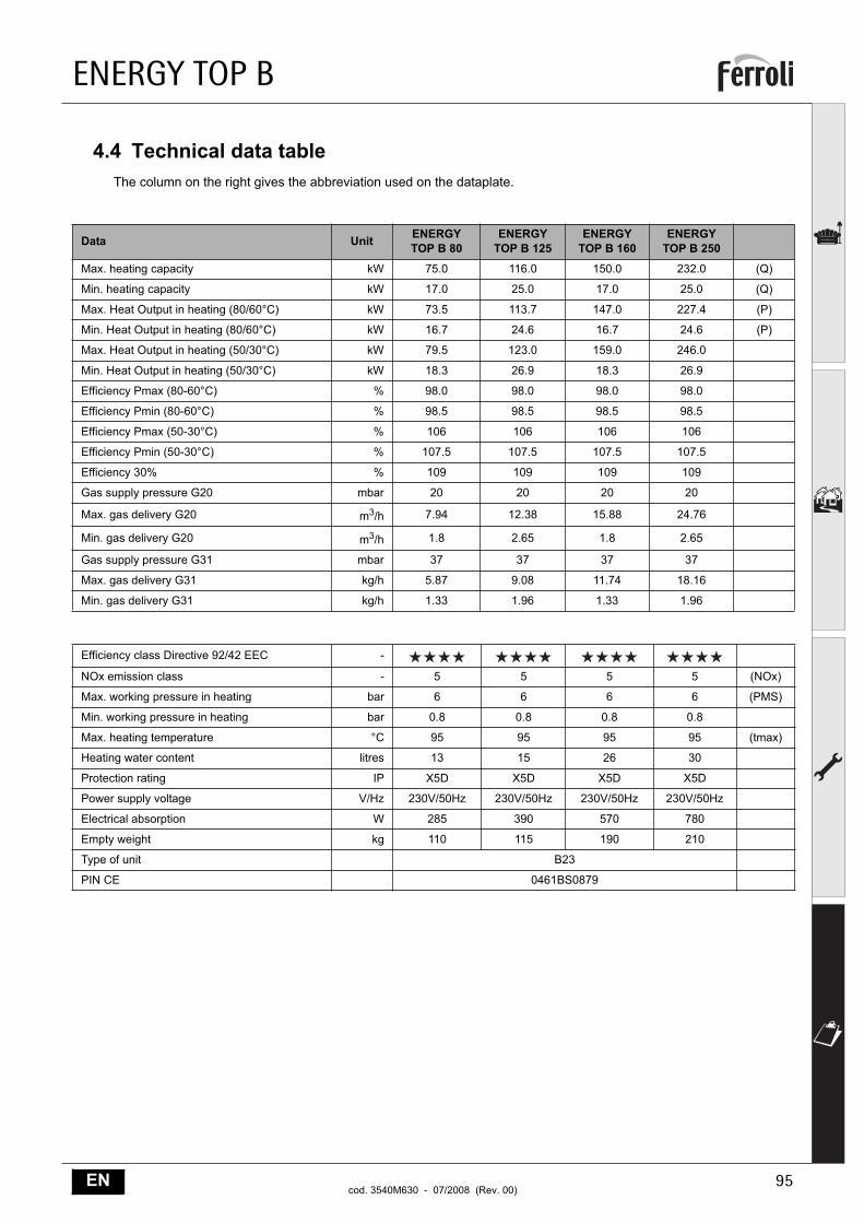
4.4 Technical data tableThe column on the right gives the abbreviation used on the dataplate.
Data Unit ENERGY TOP B 80
ENERGY TOP B 125
ENERGYTOP B 160
ENERGY TOP B 250
Max. heating capacity kW 75.0 116.0 150.0 232.0 (Q)
Min. heating capacity kW 17.0 25.0 17.0 25.0 (Q)
Max. Heat Output in heating (80/60°C) kW 73.5 113.7 147.0 227.4 (P)
Min. Heat Output in heating (80/60°C) kW 16.7 24.6 16.7 24.6 (P)
Max. Heat Output in heating (50/30°C) kW 79.5 123.0 159.0 246.0
Min. Heat Output in heating (50/30°C) kW 18.3 26.9 18.3 26.9
Efficiency Pmax (80-60°C) % 98.0 98.0 98.0 98.0
Efficiency Pmin (80-60°C) % 98.5 98.5 98.5 98.5
Efficiency Pmax (50-30°C) % 106 106 106 106
Efficiency Pmin (50-30°C) % 107.5 107.5 107.5 107.5
Efficiency 30% % 109 109 109 109
Gas supply pressure G20 mbar 20 20 20 20
Max. gas delivery G20 m3/h 7.94 12.38 15.88 24.76
Min. gas delivery G20 m3/h 1.8 2.65 1.8 2.65
Gas supply pressure G31 mbar 37 37 37 37
Max. gas delivery G31 kg/h 5.87 9.08 11.74 18.16
Min. gas delivery G31 kg/h 1.33 1.96 1.33 1.96
Efficiency class Directive 92/42 EEC -
NOx emission class - 5 5 5 5 (NOx)
Max. working pressure in heating bar 6 6 6 6 (PMS)
Min. working pressure in heating bar 0.8 0.8 0.8 0.8
Max. heating temperature °C 95 95 95 95 (tmax)
Heating water content litres 13 15 26 30
Protection rating IP X5D X5D X5D X5D
Power supply voltage V/Hz 230V/50Hz 230V/50Hz 230V/50Hz 230V/50Hz
Electrical absorption W 285 390 570 780
Empty weight kg 110 115 190 210
Type of unit B23
PIN CE 0461BS0879
ENERGY TOP B
96 ENcod. 3540M630 - 07/2008 (Rev. 00)
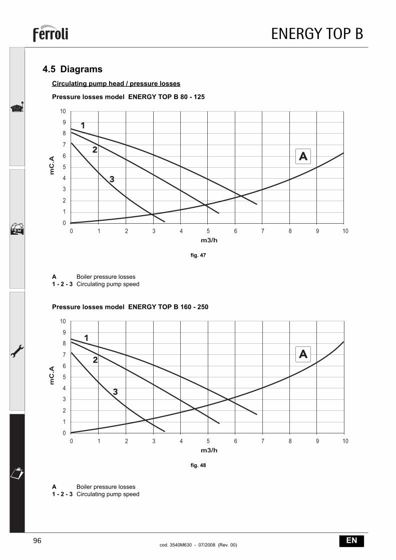
4.5 DiagramsCirculating pump head / pressure losses
Pressure losses model ENERGY TOP B 80 - 125
fig. 47
A Boiler pressure losses1 - 2 - 3 Circulating pump speed
Pressure losses model ENERGY TOP B 160 - 250
fig. 48
A Boiler pressure losses1 - 2 - 3 Circulating pump speed
�
�
�
�
�� � � � � � �
�
)�
���*
�
�
�
�
�
�
�
��
� ��
��
�
�
� � � � � � �
���*
� ���
�
)�
�
�
�
�
�
�
�
��
ENERGY TOP B
97ENcod. 3540M630 - 07/2008 (Rev. 00)
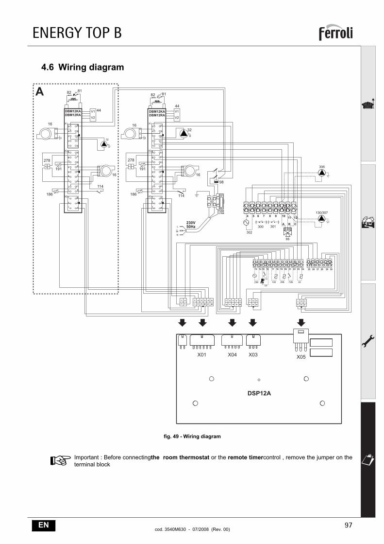
4.6 Wiring diagram
fig. 49 - Wiring diagram
AImportant : Before connectingthe room thermostat or the remote timercontrol , remove the jumper on theterminal block
$+$
+
���,��-.
�
���
��
�� ���
�
��
�� ��
��
��
��
��
��
��
�
�
�
� � � � � �
� � � �� �� ��
� � �
� � �
� � � � �
� � � � ��
&/"��)���
$+$
+
��!��0�
�
���
��
��
���
�
��
�� ��
��
��
��
��
��
��
�
�� �� �� �� �� ��
� �
� �
� � �
� � �
�"#���
��� ��� ��� ���
�� �� �� �� �� �� �� �� �� �� �� ��
���
��
��� �� ��
� � � � � � �� �� ��' '' '��� ���
�
���
�������
���
� �
��!��%���!��0���!��%�
��
ENERGY TOP B
98 ENcod. 3540M630 - 07/2008 (Rev. 00)
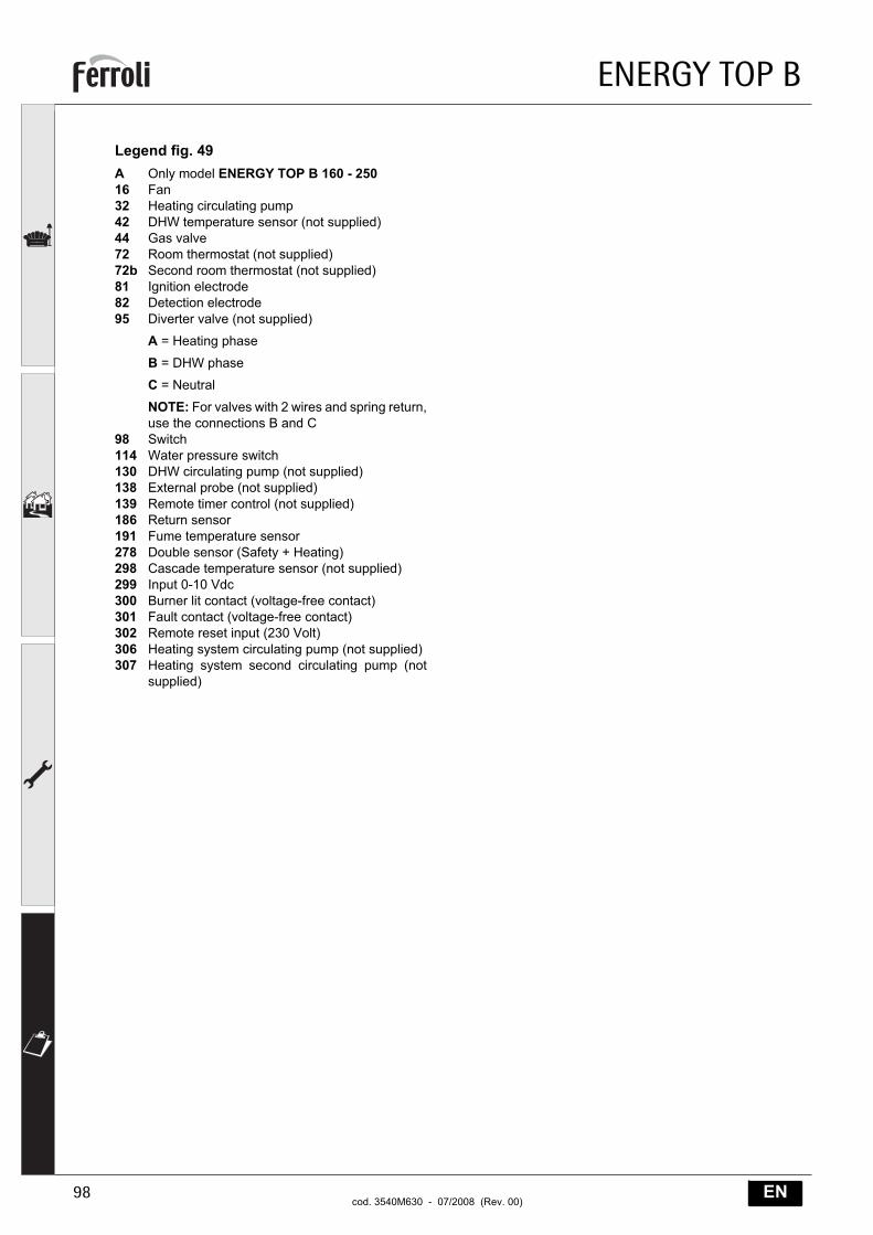
Legend fig. 49A Only model ENERGY TOP B 160 - 25016 Fan32 Heating circulating pump42 DHW temperature sensor (not supplied)44 Gas valve72 Room thermostat (not supplied)72b Second room thermostat (not supplied)81 Ignition electrode82 Detection electrode95 Diverter valve (not supplied)
A = Heating phase
B = DHW phase
C = Neutral
NOTE: For valves with 2 wires and spring return,use the connections B and C
98 Switch114 Water pressure switch130 DHW circulating pump (not supplied)138 External probe (not supplied)139 Remote timer control (not supplied)186 Return sensor191 Fume temperature sensor278 Double sensor (Safety + Heating)298 Cascade temperature sensor (not supplied)299 Input 0-10 Vdc300 Burner lit contact (voltage-free contact)301 Fault contact (voltage-free contact)302 Remote reset input (230 Volt)306 Heating system circulating pump (not supplied)307 Heating system second circulating pump (not
supplied)
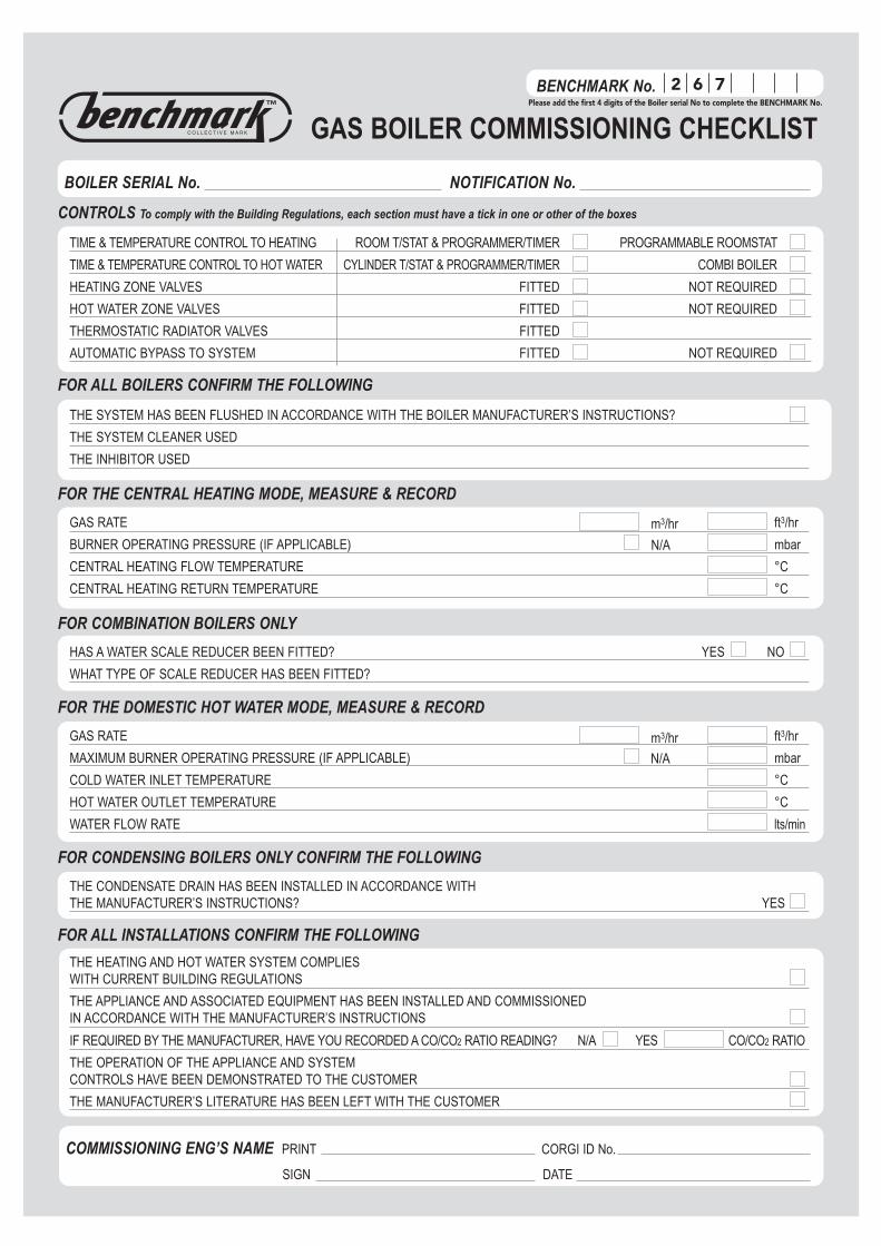
BENCHMARK
CONTROLS To comply with the Building Regulations, each section must have a tick in one or other of the boxes
TIME & TEMPERATURE CONTROL TO HEATING ROOM T/STAT & PROGRAMMER/TIMER PROGRAMMABLE ROOMSTAT
TIME & TEMPERATURE CONTROL TO HOT WATER CYLINDER T/STAT & PROGRAMMER/TIMER COMBI BOILER
HEATING ZONE VALVES FITTED NOT REQUIRED
HOT WATER ZONE VALVES FITTED NOT REQUIRED
THERMOSTATIC RADIATOR VALVES FITTED
AUTOMATIC BYPASS TO SYSTEM FITTED NOT REQUIRED
FOR ALL BOILERS CONFIRM THE FOLLOWING
THE SYSTEM HAS BEEN FLUSHED IN ACCORDANCE WITH THE BOILER MANUFACTURER’S INSTRUCTIONS?
THE SYSTEM CLEANER USED
THE INHIBITOR USED
FOR THE CENTRAL HEATING MODE, MEASURE & RECORD
GAS RATE ft3/hr
BURNER OPERATING PRESSURE (IF APPLICABLE) mbar
CENTRAL HEATING FLOW TEMPERATURE °C
CENTRAL HEATING RETURN TEMPERATURE °C
FOR COMBINATION BOILERS ONLY
HAS A WATER SCALE REDUCER BEEN FITTED? YES NO
WHAT TYPE OF SCALE REDUCER HAS BEEN FITTED?
FOR THE DOMESTIC HOT WATER MODE, MEASURE & RECORD
GAS RATE ft3/hr
MAXIMUM BURNER OPERATING PRESSURE (IF APPLICABLE) mbar
COLD WATER INLET TEMPERATURE °C
HOT WATER OUTLET TEMPERATURE °C
WATER FLOW RATE lts/min
FOR CONDENSING BOILERS ONLY CONFIRM THE FOLLOWING
THE CONDENSATE DRAIN HAS BEEN INSTALLED IN ACCORDANCE WITH THE MANUFACTURER’S INSTRUCTIONS? YES
FOR ALL INSTALLATIONS CONFIRM THE FOLLOWING
THE HEATING AND HOT WATER SYSTEM COMPLIES WITH CURRENT BUILDING REGULATIONS
THE APPLIANCE AND ASSOCIATED EQUIPMENT HAS BEEN INSTALLED AND COMMISSIONEDIN ACCORDANCE WITH THE MANUFACTURER’S INSTRUCTIONS
IF REQUIRED BY THE MANUFACTURER, HAVE YOU RECORDED A CO/CO2 RATIO READING? N/A YES CO/CO2 RATIO
THE OPERATION OF THE APPLIANCE AND SYSTEM CONTROLS HAVE BEEN DEMONSTRATED TO THE CUSTOMER
THE MANUFACTURER’S LITERATURE HAS BEEN LEFT WITH THE CUSTOMER
m3/hr
m3/hr
COMMISSIONING ENG’S NAME PRINT CORGI ID No.
SIGN DATE
BOILER SERIAL No. NOTIFICATION No.
BENCHMARK No.
GAS BOILER COMMISSIONING CHECKLISTC O L L E C T I V E M A R K
N/A
N/A
2 6 7Please add the first 4 digits of the Boiler serial No to complete the BENCHMARK No.
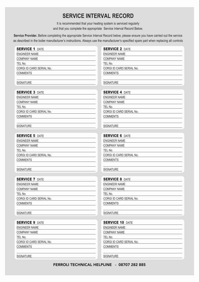
SERVICE INTERVAL RECORDIt is recommended that your heating system is serviced regularly
and that you complete the appropriate Service Interval Record Below.
Service Provider. Before completing the appropriate Service Interval Record below, please ensure you have carried out the service
as described in the boiler manufacturer’s instructions. Always use the manufacturer’s specified spare part when replacing all controls
SERVICE 1 DATE
ENGINEER NAME
COMPANY NAME
TEL No.
CORGI ID CARD SERIAL No.
COMMENTS
SIGNATURE
SERVICE 2 DATE
ENGINEER NAME
COMPANY NAME
TEL No.
CORGI ID CARD SERIAL No.
COMMENTS
SIGNATURE
SERVICE 3 DATE
ENGINEER NAME
COMPANY NAME
TEL No.
CORGI ID CARD SERIAL No.
COMMENTS
SIGNATURE
SERVICE 4 DATE
ENGINEER NAME
COMPANY NAME
TEL No.
CORGI ID CARD SERIAL No.
COMMENTS
SIGNATURE
SERVICE 5 DATE
ENGINEER NAME
COMPANY NAME
TEL No.
CORGI ID CARD SERIAL No.
COMMENTS
SIGNATURE
SERVICE 6 DATE
ENGINEER NAME
COMPANY NAME
TEL No.
CORGI ID CARD SERIAL No.
COMMENTS
SIGNATURE
SERVICE 7 DATE
ENGINEER NAME
COMPANY NAME
TEL No.
CORGI ID CARD SERIAL No.
COMMENTS
SIGNATURE
SERVICE 8 DATE
ENGINEER NAME
COMPANY NAME
TEL No.
CORGI ID CARD SERIAL No.
COMMENTS
SIGNATURE
SERVICE 9 DATE
ENGINEER NAME
COMPANY NAME
TEL No.
CORGI ID CARD SERIAL No.
COMMENTS
SIGNATURE
SERVICE 10 DATE
ENGINEER NAME
COMPANY NAME
TEL No.
CORGI ID CARD SERIAL No.
COMMENTS
SIGNATURE
FERROLI TECHNICAL HELPLINE - 08707 282 885

Phone numbers:
Installer
Service Engineer
BECAUSE OF OUR CONSTANT ENDEAVOUR FOR IMPROVEMENT DETAILSMAY VARY SLIGHTLY FROM THOSE QUOTED IN THESE INSTRUCTIONS.
ALL SPECIFICATIONS SUBJECT TO CHANGE
Please note - to avoid incurring unnecessary expense, in the event of a boiler shut down, check this is not caused by lack of electricity supply, gas supply or low water pressure before calling our
Customer Service Helpline.
Lichfield Road, Branston Industrial Estate, Burton Upon Trent, Staffordshire DE14 3HDTel. 08707 282 885 - Fax 08707 282 886
EIRE only: HEATOVENT Greenhills Industrial Estate,
Greenhills Road, Walkinstown, Dublin 12, IRELANDTel 014508166 - Fax 014508501
Should you require any assistance during the installationcall our Technical Service Helpline on
08707 282 885 option 1Should you require a service engineer to visit
call our service centre on08707 282 885 option 2
(For U.K. and Northern Ireland)
For EIRE only call HEATOVENT on014508166