Embed Size (px)
Citation preview

A DOUBLY-FED INDUCTION GENERATOR AND
ENERGY STORAGE SYSTEM FOR WIND
POWER APPLICATIONS
by
Chad Abbey
B.Eng. (University of Alberta, Edmonton, Alberta)
A thesis submitted to the Department of Electrical and Computer
Engineering in partial fulfillment of the requirements of the degree of
Master in Engineering
Department of Electrical and Computer Engineering,
McGill University,
Montréal, Québec, Canada
August 2004
© Chad Abbey, 2004

1+1 Library and Archives Canada
Bibliothèque et Archives Canada
Published Heritage Branch
Direction du Patrimoine de l'édition
395 Wellington Street Ottawa ON K1A ON4 Canada
395, rue Wellington Ottawa ON K1A ON4 Canada
NOTICE: The author has granted a nonexclusive license allowing Library and Archives Canada to reproduce, publish, archive, preserve, conserve, communicate to the public by telecommunication or on the Internet, loan, distribute and sell th es es worldwide, for commercial or noncommercial purposes, in microform, paper, electronic and/or any other formats.
The author retains copyright ownership and moral rights in this thesis. Neither the thesis nor substantial extracts from it may be printed or otherwise reproduced without the author's permission.
ln compliance with the Canadian Privacy Act some supporting forms may have been removed from this thesis.
While these forms may be included in the document page count, their removal does not represent any loss of content from the thesis.
• •• Canada
AVIS:
Your file Votre référence ISBN: 0-494-06539-7 Our file Notre référence ISBN: 0-494-06539-7
L'auteur a accordé une licence non exclusive permettant à la Bibliothèque et Archives Canada de reproduire, publier, archiver, sauvegarder, conserver, transmettre au public par télécommunication ou par l'Internet, prêter, distribuer et vendre des thèses partout dans le monde, à des fins commerciales ou autres, sur support microforme, papier, électronique et/ou autres formats.
L'auteur conserve la propriété du droit d'auteur et des droits moraux qui protège cette thèse. Ni la thèse ni des extraits substantiels de celle-ci ne doivent être imprimés ou autrement reproduits sans son autorisation.
Conformément à la loi canadienne sur la protection de la vie privée, quelques formulaires secondaires ont été enlevés de cette thèse.
Bien que ces formulaires aient inclus dans la pagination, il n'y aura aucun contenu manquant.


Abstract
Wind generation has become the most important alternate energy source and has
experienced increased growth in Europe during the past decade while more recently, the
same trends have been exhibited in North America. Although it has great potential as an
alternative to less environmentally friendly energy sources, there are various technical
challenges that cause wind to be regarded negatively by many utilities. Others are hesitant
to accept its widespread implementation, particularly when the penetration of wind in a
given area is high.
The problems of wind are associated with dependence on the local environrnental
conditions. Variability of the wind speed causes oscillations in the output power of the
wind generators, resulting in a variety of consequences within the power system and in its
operation. Although sorne power control can be enacted using mechanical means, this
usually implies a decrease in overall power capture and during calm conditions, these
solutions can no longer offer any improvement over the situation. For these reasons,
added to the fact that reactive power and weak system interconnection are often relevant
concerns, wind parks are often susceptible to voltage and transient instability problems.
This work presents the addition of an energy storage system to a wind turbine design.
The control philosophy of the conventional generator and its representation are discussed
initially, followed by a modification of the turbine design to incorporate the storage
system. The conventional and energy storage designs are compared on a single machine
basis as well as on the system level.
Various advantages are exhibited for the wind turbine with energy storage. Firstly, the
generator is capable of accurately controlling the output power of the generator and
inevitably of the wind park. Reactive power requirements are also reduced as a result of a
more stable voltage at the point of interconnection. In addition, improved transient
performance is exhibited for various local disturbances.
11

Résumé
Au cours des dix dernières années, les éoliennes sont devenues la méthode la plus
importante de génération d'énergie électrique alternative en Europe et, plus récemment,
en Amérique du Nord. Bien que la production d'électricité par le vent ait beaucoup
d'avantages au niveau de l'impact sur l'environnement, il existe plusieurs inconvénients
techniques à considérer. Plusieurs compagnies d'électricité hésitent donc à intégrer cette
forme d'électricité, surtout dans certaines régions où il y a une forte concentration
d'éoliennes.
Les problèmes associés avec la production d'électricité utilisant le vent sont reliés aux
conditions environnementales, notamment la vitesse du vent. Les fluctuations de la
vitesse du vent causent des oscillations dans l'énergie produite par les génératrices, ce qui
peut avoir des impacts négatifs sur le réseau électrique. Bien qu'il existe des méthodes
mécaniques pour limiter l'impact de cette variation, leur utilisation entraîne une réduction
de l'énergie totale fournie. De plus, pendant les périodes généralement calmes, ces
solutions ne s'avèrent pas efficaces. Ajoutés aux demandes de puissance réactives et au
fait que souvent l'interconnexion est faite à un système faible, les parcs d'éoliennes ont
souvent des problèmes d'instabilité transitoire et de contrôle de tension.
Ce mémoire présente l'addition d'un système de stockage d'énergie à une éolienne.
La théorie du contrôle d'une génératrice conventionnelle et sa représentation sont
discutées, suivie par la modification pour l'incorporation du système de stockage
d'énergie. Basés sur les deux topologies, les performances des deux systèmes sont
comparées au niveau d'une seule machine et au niveau de parc d'éoliennes.
Les caractéristiques et avantages de l'éolienne associée à un stockage d'énergie sont
présentes. La génératrice peut précisément contrôler sa puissance réelle et les demandes
de puissance réactive sont réduites grâce à un contrôle de la tension au point de
raccordement. De plus, le comportement performance transitoire suite à des défauts sur le
réseau est nettement améliorée.
111

Acknowledgements
l would like to thank my supervisor and friend, Géza J06s, for his guidance and help
during my master's studies. He has greatly helped me by providing his insight,
knowledge, and perspective when required while giving me the space and time to grow
on my own. Through his aid l have been able to enrich my theoretical knowledge while
maintaining a grasp on the needs of the industry through continued communication with
our partners in the field.
l am very grateful to my friends and colleagues in the Power Research Group in
McGill University for their support and friendship, in particular, Prof. Boon Teck Ooi
whose advice and expertise were greatly appreciated. As well, l would like to thank Prof.
Francisco Galiana, Lianwei Jiao, Fengquan Zhou, Alaa Abdul Samad, Cuauhtemoc
Rodriguez, Baike Shen, François Bouffard, Ming Zou, Natalia Alguacil, José Arroyo
Sanchez, Yougjun Ren, Hugo Gil, Khalil El-Aroudi, José Restrepo, and Sameh El
Khatib.
l would like to extend my thanks and appreciation to my colleagues at Hydro-Québec,
Bahram Khodabakhchian, Jean Mahsehdijan, and Alain Vallée, arnong others, for their
advice, guidance, and friendship. Their involvement has helped to give me an industry
perspective and added relevance to my work.
The financial support from the Natural Sciences and Engineering Research Council of
Canada and McGill University are gratefully acknowledged.
Finally l would like to thank my parents, Bonnie and Thomas, as well as my two
brothers, Josh and Tyler, and sister, Chelsea for their continued support. Also, special
thanks to my lovely girlfriend, Valérie and to her parents, Jacques and Sylvie Chénard.
Their love and support helped to make it all possible.
IV
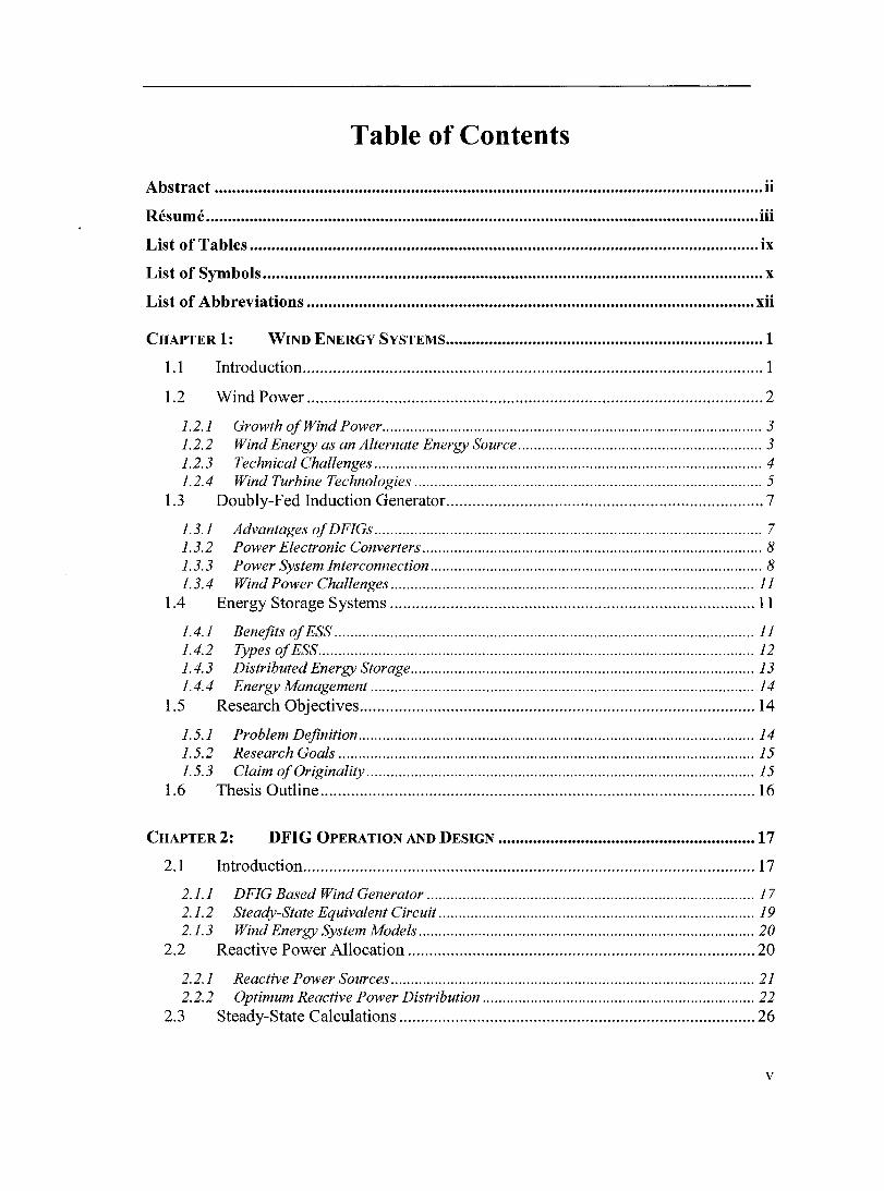
Table of Contents
Abstract .............................................................................................................................. ii
Résumé ............................................................................................................................... iii
List of Tables ..................................................................................................................... ix
List of Symbols ................................................................................................................... x
List of Abbreviations ....................................................................................................... xii
CHAPTER1: WIND ENERGY SySTEMS ......................................................................... 1
1.1
1.2
1.2.1 1.2.2 1.2.3 1.2.4
1.3
1.3.1 1.3.2 1.3.3 1.3.4
1.4
1.4.1 1.4.2 1.4.3 1.4.4
1.5
1.5.1 1.5.2 1.5.3
1.6
Introduction .......................................................................................................... 1
Wind Power ......................................................................................................... 2
Growth ofWind Power ................................................. .............................................. 3 Wind Energy as an Alternate Energy Source .............. ............................................... 3 Technical Challenges ................................................................................................. 4 Wind Turbine Technologies .............. ......................................................................... 5
Doubly-Fed Induction Generator ......................................................................... 7
Advantages of DFIGs ................................................................................................. 7 Power Electronic Converters ..................................................................................... 8 Power System Interconnection ................................................................................... 8 Wind Power Challenges ........................................................................................... Il
Energy Storage Systems .................................................................................... Il
Benefits of ESS ......................................................................................................... Il Types of ESS .......... ................................................................................................... 12 Distributed Energy Storage ............................................... ....................................... 13 Energy Management ................................................................................................ 14
Research Objectives ........................................................................................... 14
Problem Definition ........ ........................................................................................... 14 Research Goals ........................................................................................................ 15 Claim of Originality ........... ...................................................................................... 15
Thesis Outline .................................................................................................... 16
CHAPTER2: DFIG OPERATION AND DESIGN ........................................................... 17
2.1
2.1.1 2.1.2 2.1.3
2.2
2.2.1 2.2.2
2.3
Introduction ........................................................................................................ 17
DFIG Based Wind Generator .................................................................................. 17 Steady-State Equivalent Circuit .. ............................................................................. 19 Wind Energy System Models .................................................................................... 20
Reactive Power Allocation ................................................................................ 20
Reactive Power Sources .... ....................................................................................... 21 Optimum Reactive Power Distribution .................................................................... 22
Steady-State Calculations .................................................................................. 26
v

2.4 Conclusions ........................................................................................................ 29
CHAPTER3: TRANSIENT MODELS AND CONTROL .................................................... 30
3.1
3.2
3.2.1 3.2.2 3.2.3
3.3
3.3.1 3.3.2
3.4
3.4.1 3.4.2 3.4.3
3.5
Introduction ........................................................................................................ 30
Converter Controls ............................................................................................. 30
Current Control ..................................................................... ................................... 30 Real and Reactive Power Control.. .......................................................................... 32 Line Side Converter Control .................................................................................... 34
Higher Leve1 Control SignaIs ............................................................................ 34
Speed Control .................................................................... ....................................... 34 Ac Voltage Regulation ................................................................ .............................. 35
Control Verification ........................................................................................... 36
Decoupled Control of Ps and Qs .............................................................................. 36 Speed Control ............................................................................. .............................. 38 Dc Voltage Regulation ............................................................................................. 40
Conclusions ........................................................................................................ 41
CHAPTER4: INTEGRATION OF ENERGY STORAGE ................................................... 42
4.1
4.2
4.2.1 4.2.2 4.2.3
4.3
4.3.1 4.3.2
4.4
Introduction ........................................................................................................ 42
Energy Storage System ...................................................................................... 43
DFIG and ESS System and Rating ........................................................................... 44 Energy Storage Control ........................................................................................... 45 Energy Storage Limitations ............................................ .......................................... 47
System Characteristics ....................................................................................... 49
Normal Operating Characteristics ............................................................ ............... 50 Contingency Operating Characteristics ................................................................... 53
Conclusions ........................................................................................................ 54
CHAPTER5: GRID INTERCONNECTION OF DFIGs .................................................... 55
5.1
5.2
5.3
5.3.1 5.3.2
5.4
5.4.1 5.4.2
5.5
Introduction ........................................................................................................ 55
Wind Park Interconnection ................................................................................ 55
Normal Wind Farm Operation ........................................................................... 56
Real Power Production ............................................................................................ 57 Voltage Regulation ............................................................................... .................... 58
Power System Disturbances .............................................................................. 59
Asymmetrical Fau/ts ................................................................................ ................. 60 Three-Phase to Ground Fau/ts ......................................................................... ........ 63
Conclusions ........................................................................................................ 64
vi

CHAPTER6: CONCLUSIONS AND FUTURE WORK ..•.....•.•.•............•.•...•..•.•..•.•..•....•.•.. 66
6.1
6.2
6.2.1 6.2.2 6.2.3
6.3
6.3.1 6.3.2 6.3.3
Summary ............................................................................................................ 66
Conclusions ........................................................................................................ 66
Doubly-Fed Induction Generator ............................................. ................................ 67 Energy Storage ................................ ......................................................................... 67 Alternate Topologies ... ............................................................................................. 68
Future Work ....................................................................................................... 69
Energy Management .............................. .................................................................. 69 Storage Deviee Energy Management ............................................ ........................... 70 Distributed Generation and MicroGrids ............................................ ...................... 70
References ......................................................................................................................... 72
Appendix A: Wind Models ............................................................................................. 77
Appendix B: Mode) Parameters ..................................................................................... 81
Appendix C: Wind Park sec ........................................................................................ 82
Appendix D: Droop Characteristic ................................................................................ 83
Appendix E: EMTP-RV Models ..................................................................................... 84
VIl
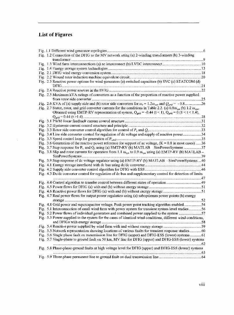
List of Figures
Fig. 1.1 Different wind generator topologies ................................................................................................... 6 Fig. 1.2 Connection of the DFIG to the MV network using (a) 2-winding transformers (b) 3-winding
transformer ........................................................................................................................................ 9 Fig. 1.3 Wind farm interconnections (a) ac interconnect (b) LVDC interconnect.. ...................................... l0 Fig. 1.4 Energy storage system technologies ................................................................................................ 13 Fig. 2.1 DFIG wind energy conversion system ............................................................................................. 18 Fig. 2.2 W ound rotor induction machine equiva1ent circuit.. ........................................................................ 20 Fig. 2.3 Reactive power options for wind generators (a) switched capacitors (b) SVC (c) STATCOM (d)
DFIG ................................................................................................................................................ 21 Fig. 2.4 Reactive power sources in the DFIG ............................................................................................... 22 Fig. 2.5 Maximum kV A ratings of converters as a function of the proportion of reactive power supplied
from rotor side converter ................................................................................................................. 25 Fig. 2.6 KV A of (a) supply side and (b) rotor side converters for W r = 1.2wsyn and Qgrid = - 0.8 ................. 26 Fig. 2.7 Stator, rotor, and grid converter currents for the conditions in Table 2.2. (a) 0.8cosyn (b) 1.2 cosyn '
Obtained using EMTP-RV representation of system, Qgrid = -0.44 (t < 1), Qgrid = 0 (1 < t < 1.4), Qgrid = 0.44 (t > 1.4) .......................................................................................................................... 28
Fig. 3.1 PWM linear feedback current control structure ............................................................................... 31 Fig. 3.2 Hysteresis current control structure and princip le ........................................................................... 32 Fig. 3.3 Rotor side converter control algorithm for control of Ps and Qs ...................................................... 33 Fig. 3.4 Line side converter control for regulation of dc voltage and supply of reactive power.. ................. 34 Fig. 3.5 Speed controlloop for generation of Ps,ref ........................................................................................ 35 Fig. 3.6 Generation of the reactive power reference for support of ac voltage, (K = 0.8 in most cases) ...... 36 Fig. 3.7 Step response for Ps and Qs using (a) EMTP-RV (b) MATLAB - SimPowerSystems .................. 37 Fig. 3.8 Slip and rotor currents for operation from 1.1 cosyn to 0.9 cosyn using (a) EMTP-RV (b) MATLAB-
SimPowerSystems ........................................................................................................................... 39 Fig. 3.9 Step response of dc voltage regulator using (a) EMTP-RV (b) MATLAB - SimPowerSystems .. .40 Fig. 4.1 Energy storage interfaced with dc bus using dc/dc converter .......................................................... 44 Fig. 4.2 Supply side converter control algorithm for DFIG with ESS .......................................................... 46 Fig. 4.3 Dc/dc converter control for regulation of dc bus and supplementary control for detection oflimits
......................................................................................................................................................... 47 Fig. 4.4 Control algorithm to transfer control between different states of operation .................................... 49 Fig. 4.5 Power flows for DFIG (a) with and (b) without energy storage ...................................................... 51 Fig. 4.6 Reactive power flows for DFIG (a) with and (b) without energy storage ....................................... 51 Fig. 4.7 Real power flows for output power regulation using (a) suboptimum power points (b) energy
storage ............................................................................................................................................. 52 Fig. 4.8 Grid power and supercapacitor voltage. Peak power point tracking algorithm enabled .................. 54 Fig. 5.1 Interconnection of smaU wind farm with power system for transient system level studies ............. 56 Fig. 5.2 Power flows ofindividual generators and combined power supplied to the system ....................... 57 Fig. 5.3 Power supplied to the system for the cases ofidentical wind conditions, different wind conditions,
and DFIGs with energy storage ....................................................................................................... 58 Fig. 5.4 Reactive power supplied by wind farm with and without energy storage ....................................... 59 Fig. 5.5 Network representation showing locations ofvarious fauIts for transient response studies ............ 60 Fig. 5.6 Single phase fauIt on transmission line for DFIG (upper) and DFIG-ESS (lower) systems ............ 61 Fig. 5.7 Single-phase to ground fault on 50 km, MV line for DFIG (upper) and DFIG-ESS (lower) systems
......................................................................................................................................................... 62 Fig. 5.8 Phase-phase-ground faults at high voltage level for DFIG (upper) and DFIG-ESS (lower) systems
......................................................................................................................................................... 63 Fig. 5.9 Three phase permanent line to ground fault on dual transmission line ............................................ 64
V111

List of Tables
Table 1.1: Comparison of wind generator design characteristics and costs ..................................................... 7 Table 1.2 Summary of energy storage system characteristics ........................................................................ 13 Table 2.1 Control objectives for converters and DFIG-WECS ...................................................................... 18 Table 2.2 Steady-state operating conditions ofDFIG .................................................................................... 28 Table 4.1 Energy storage system control for normal and limiting operation ................................................ .44 Table 5.1 Fault information for system transient response studies ................................................................ 60
IX

List of Symbols
C: csc E: EESS:
Emax :
Emin
iband :
Iconv :
iconv,q
Ir :
irej :
irq :
Is :
IsMEs J: K: LSMES
ma : n: n max :
nmin :
Pconv :
Pconv,rej :
Pe :
pl: Pgrid
Pm :
Prated :
Ps :
Ps,rej :
Qconv :
Qconv,rej :
Qgrid :
Qgrid,rej :
Qs :
Qs,rej :
Rr : Rs : Sconv
Smax :
Sr :
Srating
Te :
Capacitance Supercapacitor capacitance Stored energy Energy storage system stored energy Maximum storage capability of energy storage system Minimum storage capability of energy storage system Hysteresis band for hysteresis current control Supply side current vector for DFIG system Reactive component of supply si de converter Rotor si de current vector for DFIG system Reference current waveform Reactive component of rotor current Stator side current vector for DFIG system SMES dc current Moment of inertia of machine Reactive compensation constant SMES equivalent inductance Modulation index Transformer tums ratio Maximum transformer tums ratio Minimum transformer tums ratio Supply side converter power delivered to system Reference supply side converter power delivered to system Electromechanical power of machine Power factor Power delivered to the grid from the DFIG Mechanical input power to the machine Rated power of the machine Stator power delivered to the grid Reference stator power delivered to the grid Reactive power delivered by the supply side converter Reference reactive power delivered by the supply side converter Reactive power delivered to the grid from the DFIG Reference reactive power delivered to the grid from the DFIG Reactive power delivered to the grid Reference reactive power delivered to the grid Rotor resistance ofDFIG as seen from the stator side Stator resistance of DFIG as seen from the stator si de Reactive power supplied from supply si de converter Magnitude of maximum slip Reactive power supplied from rotor side converter Converter k V A rating Electromagnetic torque
x

Tm : Vdc :
V ess :
Vess,max
V ess, min
VLL : Vm :
Vr,ind :
VSC: Vwind
Xm :
X r :
Xs :
~ : br :
OJm
OJm,rel :
OJr :
OJs :
OJsyn :
~echanicalinputtorque
Dc voltage Energy storage system voltage ~aximum energy storage system voltage ~inimum energy storage system voltage Line-to-line voltage Voltage vector across DFIG magnetizing branch Induced voltage from rotor si de Supercapacitor dc voltage Wind velocity ~agnetizing reactance of DFIG Rotor reactance ofDFIG as seen from the stator side Stator reactance ofDFIG as seen from the stator side Wind turbine blade pitch angle Angle of rotor side voltage vector relative to stator side voltage vector, both expressed on the synchronously rotating frame ~echanical rotor angle Electrical rotor angle Angle of stator voltage vector as obtained from PLL air density ~echanical rotor angular velo city Reference mechanical rotor angular velo city Electrical rotor angular velo city Angular velo city of grid voltage vector Synchronous angular velo city
Xl

List of Abbreviations
Ac BESS CHP Dc DFIO DFIO-ESS DO EMPT-RV ESS FACTS HV HVDC 10 IPP KVA MV PCC PI PLL PMSM PWM PV SMES STATCOM SVC UPS WECS VSC
Altemating CUITent Battery energy storage system Combined heat and power Direct CUITent Doubly-fed induction generator Doubly-fed induction generator and energy storage system Distributed generation Electromagnetic Transient Pro gram - Restructured Version Energy storage system Flexible AC transmission systems High voltage High voltage DC transmission Induction generator Independent power producer Kilo volt ampere Medium voltage Point of common coupling Proportional integral Phase locked loop Permanent magnet synchronous machine Pulse width modulation Photovoltaic Superconducting magnetic energy storage system Static synchronous compensator Static Var compensator Uninterruptible power suppl y Wind energy conversion system Voltage source converter
xu
Chapter 1.' Introduction
Chapter 1: Wind Energy Systems
1.1 Introduction
During the past decade and a half, wind power has received enonnous attention and
has been identified as the most promising of alternative energy sources. Fueled by the
search for environmentally friendly sources of electrical power and the need for reliable
and large capacity fonns of renewable energy, wind energy has doubled in global
capacity every three years since 1990 [1]. The financial gains associated with the low
price of coal as a means of cheap generation to supplement either hydro or nuc1ear has
been overshadowed by public pressure to limit greenhouse gas production. Wind
installations have not only become more competitive with new coal plants in tenns of cost
but now also promise similar reliability and ancillary services which until recently was
not possible.
However, there still exist various shortcomings associated with wind energy which
makes energy producers hesitate to invest, despite its merits. Not only do es it fail to offer
the efficiency of more conventional fonns of generation but its energy production is still
c10sely coupled to the environmental conditions, thereby making it inherently stochastic
by nature. This becomes one of the greatest barriers to its high penetration in the
conventional power system wherein the generation must always meet the demand, and
thus strictly requires predictable, dispatchable fonns of generation.
Wind and most other renewables are for the most part considered to be non
dispatchable [2]. Particularly when the wind generator is a distributed generator (DG), i.e.
a single wind generator connected to the grid and usually operated by an independent
power producer (lPP), the dependence of the output power on the wind speed is high. In
the case of a wind park, the net output power tends to have smaller oscillations as a result
of the averaging effect across aIl of the generators. As weIl, supervisory controls and
1
Chapter 1: Introduction
wind forecasting can help to reduce the power fluctuations [3], [4). Therefore, the issue of
power regulation is of even greater importance in small wind parks and for DGs.
The introduction of DGs into the power system, which at the moment is still relatively
limited, has given way to a new form of grid, where the power consumed at the loads may
be produced from a number of different sources, power producers, and at various
locations. This sets the framework for a possible grid of the future with a more elaborate
and variable structure and which will require the corresponding standards for
interconnection, protection, and controls in order to ensure its smooth and stable
operation.
The recent changes in the structure of the grid have been facilitated by deregulation of
the power system, the focus on these new forms of generation, and the interconnection of
previously isolated power systems. Although ratifications to the traditional structure and
ideology of the power system are underway, new generation must still adhere to
constraints set by the operators of the transmission and power delivery systems.
Therefore, in order to continue to experience its rapid growth worldwide, wind energy
conversion systems must strive to increase their dispatchability and their ability to
provide ancillary services.
1.2 Wind Power
Wind power is perhaps the field that has experienced the most attention within the
power industry during the past five years. The prime factor that has influenced its growth
is public pressure to reduce the harmful emissions, which are typically associated with
generators utilizing coal as their fuel source. Secondly, the availability of other forms of
generation, namely hydro and nuc1ear has determined the extent to which wind and other
alternative energy sources have been exercised. This perhaps explains the relative lack of
interest in wind in Québec, other Canadian provinces, and the United States where hydro
and nuc1ear are abundant. However, the growth of wind reflects the public opinion, the
resulting political movements and govemment incentives to support its development and
this has begun to push its growth in North America as well.
2

Chapter 1: Introduction
1.2.1 Growth ofWind Power
European countries have led the way in wind power utilization and the majority of the
expertise in this field has been developed through experience in wind parks in the
Scandinavian countries, the UK, France, Spain, and Greece [5]-[12]. Only recently has
wind power been developed substantially in North America and in other parts of the
world. However, this trend is likely to increase as political reforrn takes into account
greenhouse gases and technologies improve. Wind turbines presently have capacities of
up to 3 MW (with experimental versions up to 4.5 MW) and this could reach upwards of
5 MW in the next couple of years, while turbines rated at 10 MW are expected by 2020
[2].
Various sites have been identified as having good wind energy potential including
both on- and off-shore locations and the wind installations can be subjected to very
different system characteristics. Previously, wind energy has been considered only for
distributed generators, meant only to operate in isolated systems or to supplement the
demands of a specifie load. Distributed generators for the most part are assumed to have
little effect on the system as a whole and in North America, IEEE standards are usually
followed for their interconnection and protection practices [13]. However, with the
development of large capacity machines and a better understanding of high penetration of
wind on system dynamics [14],[15],[16], wind parks can now offer similar capacities as
sorne conventional generation plants. The consequence is that their effect on the grid is
greater and as a result they must aid in support and control of the system.
1.2.2 Wind Energy as an Alternate Energy Source
The greatest advantage ofwind is that it is an environrnentally friendly forrn of energy
production. Without this characteristic, its growth would be significantly hindered since
govemment incentives have helped to make it competitive in Europe and in North
America [1],[2]. Compared with other altemate energy sources such as photovoltaics
(PV), and combined heat and power (CHP) units, wind is also non-dispatchable, however
it has the advantage ofhigh capacity and is more well suited for large installations.
In addition, wind may serve as one of the larger capacity forrns of DG while it may be
supplemented by more controllable forrns of DG either in the forrn of PV or diesel.
3

Chapter 1.' Introduction
Modeling issues for wind and other fonns of DG have been addressed [16], [17] and
attempts are now being made to look at the potential of DG to benefit the system.
Photovoltaics and small CHP willlikely required wind and other larger capacity fonns of
DG like small hydropower (which are also currently more cost effective) in order to make
the case for DG as a means of replacing transmission upgrades a realistic solution.
1.2.3 Technical Challenges
As the penetration of wind increases, the way in which it interacts with the power
system becomes increasingly important. DGs are typically required to trip during
undervoltages and other system disturbances and are not required to aid in voltage or
frequency regulation [13]. However, for high penetrations of DG, these requirements are
like1y unreasonable and in sorne cases may even be detrimental to the stability of the
system. For instance, without voltage regulation controls, the voltage may often fluctuate
outside the acceptable operating range [2], and fast tripping of wind generators following
undervoltages have been shown to lead to voltage collapse [16], suggesting the need for
low-voltage ride through capability.
The problem of voltage regulation and reactive power control is even greater in the
case of a weak connection. The large source impedance results in significant fluctuations
in the voltage at the point of common coupling (PCC) due to changes in power flows and
in this case reactive compensation has been shown to be crucial [18]. Propagation of
hannonics in the system is re1atively unimportant compared with voltage stability issues.
The ability to smooth the power oscillations will result in a more stable tenninal voltage,
however, reactive compensation would still be a strict requirement, in steady-state but
even more importantly during transients.
The response of systems with increased levels of wind energy to various transients
has been investigated [15], [16], [19]. Unlike conventional systems, the 10ss of
synchronism is not a concem since the generators are typically all asynchronous, however
overspeed and undervoltage protection causes tripping of the turbines, which can often
lead to voltage instability or collapse. From these studies, it was shown that wind parks
composed of DFIGs typically demonstrate a higher leve1 of stability due to the ability for
reactive power compensation and a greater control of the generator speed. The effect of
4

Chapter 1: Introduction
additional energy storage may further improve the DFIGs tolerance to power system
disturbances. However, definition of the various protections for this system and an
assessment of the system performance under transients are required.
1.2.4 Wind Turbine Technologies
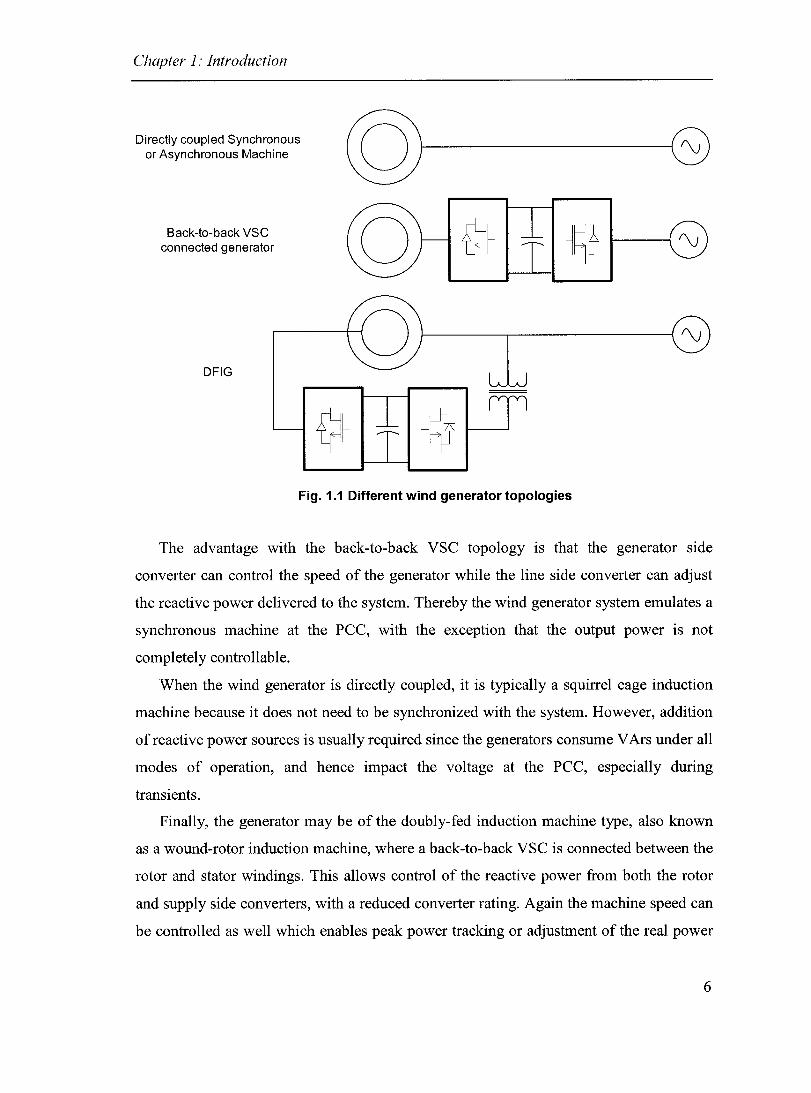
The main types of wind turbines are presented in Fig. 1.1. As mentioned, wind
generators differ from conventional generators in that variable speed generators are more
commonly used, due to the fact that optimum power capture is obtained at different rotor
speeds for different wind speeds. In addition, variable speed operation limits the
mechanical stresses on the blades resulting from wind gusts. Thus, the synchronous
generator is rarely used when directly coupled since it requires a mechanical means of
regulating the speed and lacks the benefits associated with a variable speed wind
generator.
Synchronous generators are, however, sometimes implemented and variable speed
operation is possible when the generator is connected to the system using a back-to-back
voltage source converter (VSC). Permanent magnet synchronous machines (PMSM) are
the most common choice and are typically implemented in stand-alone systems. PMSM
are often used since no field winding control is necessary and the gear-box can be
eliminated, making it low maintenance and therefore ideal for operation in remote
locations.
5
Chapter 1: Introduction
Directly coupled Synchronous or Asynchronous Machine
Back-to-back VSC connected generator
DFIG
CQ)I-----G
~I Fig. 1.1 Different wind generator topologies
The advantage with the back-to-back VSC topology is that the generator side
converter can control the speed of the generator while the line side converter can adjust
the reactive power delivered to the system. Thereby the wind generator system emulates a
synchronous machine at the PCC, with the exception that the output power is not
complete1y controllable.
When the wind generator is directly coupled, it is typically a squirrel cage induction
machine because it does not need to be synchronized with the system. However, addition
of reactive power sources is usually required since the generators consume VArs under all
modes of operation, and hence impact the voltage at the PCC, especially during
transients.
Finally, the generator may be of the doubly-fed induction machine type, also known
as a wound-rotor induction machine, where a back-to-back VSC is connected between the
rotor and stator windings. This allows control of the reactive power from both the rotor
and supply side converters, with a reduced converter rating. Again the machine speed can
be controlled as well which enables peak power tracking or adjustment of the real power
6

Chapter 1.' Introduction
output. However, the cost of the machine is greater than the case of a squirre! cage
induction machine and therefore, the additional controls come with an additional priee.
1.3 Doubly-Fed Induction Generator
The DFIG is currently the most popular machine topology for wind power
applications. The majority of large capacity machines (>1 MW) available from
manufacturers such as Vestas and General Electric-Wind are aIl DFIGs (although sorne
producers such as Entercon are favoring PMSM). The power electronic converters enable
control over the generator operating characteristics such as speed and reactive power,
features which are lacking or limited in squirre! cage induction machine. This allows for
variable speed operation for peak power point tracking or output power regulation. In
addition, the converter rating is significantly redueed compared with the stator connected
converter system.
1.3.1 Advantages of DFIGs
The main reasons that make the DFIG a popular choice for wind power applications
include its ability for variable speed operation, reactive power control, and redueed
converter ratings. Due to the fact that the rotor side presents voltages, which are at most
20% of the stator si de voltage, the minimum kVA rating of the converter is approximately
20% that of the case of a back-to-back converter connected machine. Table 1.1
summarizes the differences between the three main wind generator topologies.
Table 1.1: Comparison of wind generator design characteristics and
costs
using pitch angle
30-50% machine Two reactive power Pitch control and Low converter cost,
rating sources converter control machine expensive
Full machine rating Reactive power Pitch control and Machine inexpensive,
control converter control converter cost high
7

Chapter 1: Introduction
1.3.2 Power Electronic Converters
The converters that are connected between the rotor and the stator of the machine are
typically back-to-back VSC, however a matrix converter could be used altematively. The
advantages compared with the VSC connected machine is that the converter rating is
reduced by about factor of between 2 and 5, since the rating is now based upon rotor
voltages which are related to the speed range of the machine. The rotor voltages are
related to the stator voltages by:
(1.1 )
where the machine slip, s is a measure of the rotor speed relative to synchronous speed,
which is given by:
n,yn - n r S=--'--- (1.2)
The converter rating is then defined by the maximum speed and the maximum stator
CUITent and voltage at that speed. The tums ratio which exists across the machine has
been assumed to be 1 for simplicity and therefore, the rotor CUITent magnitude is equal to
the stator CUITent magnitude. If the upper speed limit is taken to be 1.2 of synchronous
speed then the minimum converter rating will be 20% that of the machine's rating.
However, for practical purposes a rating of 30-50% might be used taking into account
transient operation and the ability to deliver reactive power from the stator.
1.3.3 Power System Interconnection
The DFIG is connected to the medium voltage (MV) level of the power system by a
step-up transformer. Since the 1ine side converter typically requires an additiona1
transformer to match the converter output voltage to the li ne voltage, either two, 2-
winding transformers or one, 3-winding transformer may be used Fig. 1.2.
8

Chapter 1: Introduction
20/0.690 kV
(a) (b)
Fig. 1.2 Connection of the DFIG to the MV network using (a) 2-winding transformers (b)
3-winding transformer
Typically in a wind park, numerous wind generators would be connected to the MV
bus which would then be connected to the high voltage feeder via another transformer.
High voltage dc (HVDC) transmission systems have been considered for integration of
wind with the ac system, however, it seems to be only economically feasible for very
large installations, located far offshore [8],[9]. Recently low voltage dc transmission
(L VDC) has received interest as a possible compromise between HVDC and ac
interconnection, with the advantages of HVDC at a reduced cost [20]. However, in most
cases an ac intertie is the preferred method of interconnection. These wind park
arrangements are presented in Fig. 1.3.
Wind parks are typically only connected at a single point although reliability could be
improved if connection to multiple feeders was done. Particularly in the case of offshore
installations, the cost associated with multiple interties compounded with the strict
environmental regulations make the connection of a radial wind farm at a single point to
the transmission system the norm.
The interconnection of the wind farm is often to a weak system, which amplifies
many of the technical difficulties associated with wind generators [18]. In this case,
fluctuating output power results in a highly variable voltage at the PCC and therefore,
reactive power control is required to help regulate the system voltage. The response ofthe
system following faults in this case is also of great concem and the undervoltage and
overspeed protections must be carefully chosen [21].
9

Chapter 1: Introduction
Future wind park projects have been limited by a number of factors, most importantly,
issues related to transmission [1]. Since new installations are usually located away from
central generation and load centers, transmission problems have slowed their progress.
Although many sites have access to rural distribution networks, the transmission system
is usually very weak or inadequate to support large amounts of generation. The problem
is complicated further when the generation is unpredictable, resulting in similar changes
in the bus voltage. This emphasizes the need for reactive power control but also the
ability to smooth the power fluctuations due to the wind dynamics.
WG1
HV
(a)
GRID WGn-1
WGn
WG 1
(b)
WGn_1
Fig. 1.3 Wind farm interconnections (a) ac interconnect (b) LVDC interconnect
10
Chapter 1: Introduction
1.3.4 Wind Power Challenges
The challenges associated with operation of a wind farrn 1ead to a greater concem for
the operation under disturbances within the nearby power system. Asymmetric and
symmetric faults can 1ead to voltage instabilities and 10ss of synchronism in traditiona1
power systems. Since wind farrns are typically composed of on1y induction machines,
10ss of stability is no longer a concem. However, tripping of the generators due to
undervoltage and overspeed of the generators can result in voltage stability prob1ems and
even small disturbances may 1ead to widespread tripping and associated instabi1ities.
Reactive power compensation can he1p to improve transient stability and the integration
of energy storage into variable reactive power sources has shown to provide a further
increase in the transient stability of the system [22].
1.4 Energy Storage Systems
Although storage of energy is used extensive1y in 10w power applications, viable,
10w-cost energy storage devices still do not exist present1y. In the conventiona1 uti1ity,
power is produced at one location in the system and consumed at another, connection
between the two points being accompli shed by the transmission network. However, many
benefits can be realized through application of a short terrn energy storage device and
energy storage systems (ESS) have been utilized in various applications, despite their
consistent1y e1evated costs [19] ,[23 ],[24 ],[25].
1.4.1 Benefits ofESS
Energy storage has been used for vanous applications inc1uding transportation,
flexible ac transmission systems (F ACTS), and uninterruptib1e power supplies (UPS).
The main benefits can be summarized by:
(i) Instantaneous exchange of rea1 power with the system using power e1ectronic
interface.
(ii) Enab1es both storage and supp1y of energy
(iii) Short terrn supp1y prevents multiple switching ofback-up generators
11

Chapter 1: Introduction
(iv) Integration of ESS with FACTS has been shown to further llnprove the
transient stability
(v) Smoothing of the output power from non-dispatchable energy sources
The final two points can be taken advantage of for wind power applications.
Integration of energy storage into the wind energy conversion system (WECS) can
improve the ability to dispatch the wind generator. Aiso the transient stability of the wind
park is improved while the associated transmission system benefits from this design
choice.
1.4.2 Types of ESS
There exist numerous types of ESS, and each is modeled somewhat differently. Fig.
1.4 presents the four most common systems which are available today. Each of the
systems realizes the same goal, however, the manner in which they store energy is quite
different and consequently, their modeling and control differs significantly as well.
Various factors need to be considered when choosing the type of energy storage
system including: size, rating, speed, and cost. Sorne storage devices are better suited for
larger ratings and the speed of ex change of energy also typically differs. As is expected
the cost differs greatly between the various elements and for this reason, flywheels are
commonly used in higher power applications since it is the most competitive in this
respect. Table 1.2 summarizes the characteristics of the different technologies.
12

Chapter 1: Introduction
T ~ l'
-@
Battery Energy Storage System
(BESS)
Supercapacitors
Supermagnetic Energy Storage
System (SMES)
Flywheel
Fig. 1.4 Energy storage system technologies
Table 1.2 Summary of energy storage 'system characteristics
10MW MJ
1 2 5-100 1kJ-1O Seconds- 2000 - 5 - 20 E(t) = -CVsc kW MJ minutes 10000 2
1 2 1- 50 1-100 Seconds 300 - 1000 30-50 E(t) = 2' LsmeJsmes MW MJ
1 2 1 kW- 1 - 15 MJ Minutes 1000 - 0.3 - 2 E(t) = -JOJfiv
10MW 10000 2 .
1 - taken from [26], 2 -taken from [27],[28]
1.4.3 Distributed Energy Storage
In wind power applications, the location of the energy storage device may be either in
each of the generators or lumped at one point, such as in the dc bus of a static
compensator (STATCOM) connected at the PCC. In the case of a DFIG, the ·dc link is
already required, and therefore, it is reasonable to incorporate the ESS in the dc bus. In
13
Chapter 1: Introduction
this way the ESS device, in the form of BESS or supercapacitors is located within each of
the DFIGs.
For this arrangement, it could be argued that the system is more reliable compared to
the case where the ESS is concentrated at one location. This is due to the fact that if one
of the DFIGs is disconnected from the system, only a portion of the energy storage
capability of the system is lost. In the case where the STATCOM with ESS is out of
service, the wind farm reduces to the conventional case and all of the benefits of energy
storage are lost.
1.4.4 Energy Management
The addition of energy storage to a WECS introduces new complexity into the system
since now the limits of the storage device must be taken into account. Since the cost of
the storage device is a function of its rating, the system should be sized to be as small as
possible in order to minimize its price and physical dimensions. This requires that the
control system be able to handle extraneous conditions, whereby either the upper or lower
limits of the ESS are attained. Not only must the control be able to handle these
conditions but it must be able to transfer control back to normal operation to once again
reap the benefits of the ESS. Therefore, the advantages associated with energy storage
corne with an increase in both cost and control complexity.
1.5 Research Objectives
The focus ofthis research is on the utilization of the doubly-fed induction machine as
a wind powered generator. Furthermore, the integration of an energy storage device into
the wind generator design is considered. The study is conducted first on a single generator
system, followed by addition of the energy storage element and its control, and finally the
investigation of the system characteristics when connected to a distribution feeder.
1.5.1 Problem Definition
The problem of this research is to understand and implement the control of a wind
powered DFIG. Once the basic generator has been constructed and its control is verified,
then the energy storage is added. The secondary problem becomes the control of the ESS
14

Chapter 1: Introduction
itself, under both normal operating conditions and abnormal operation. Finally, the
benefits of this type of generator design on a system level needs to be evaluated.
1.5.2 Research Goals
The research should accomplish the following tasks:
1. Investigation of stator and rotor reactive power distribution and overall converter
rating minimization.
2. Integration and control of energy storage into the DFIG converter system.
3. Demonstrate that a DFIG and ESS can regulate the output power under normal
circumstances and thereby make wind energy dispatchable.
4. Demonstrate proper energy management under normal and abnorrnal conditions.
5. Investigate the operation of the system and show how energy storage can improve
transient stability and power quality.
6. Develop simulation models within EMTP-RV in collaboration with TransÉnergie
Technologie and Hydro-Québec, inc1uding technology transfer of documents and
models.
1.5.3 Claim of Originality
This thesis has contributed various original ideas in this field of study. The method of
reactive power distribution discussed within Chapter 2 was not looked at before as a
means of minimizing the converter ratings. As well, the application of energy storage to
the DFIG wind generator has not been looked at previously in the literature. Although the
idea of applying energy storage to fluctuating power generators is not unique, the
implernentation for this topology and the control philosophy, to the best of the author' s
knowledge is original.
15

Chapter 1: Introduction
1.6 Thesis Outline
The thesis is organized into a total of six chapters including this introduction. Chapter
2 introduces the details of the DFIG system and discusses the basis for its control.
Following this, the transient models are developed in Chapter 3 and the control is verified
using two simulation platforrns: EMTP-RV and MATLAB SimPowerSystems. Energy
storage is discussed in depth in Chapter 4 and its feasibility is demonstrated. Chapter 5
presents the operation of the system in a distribution network and the response following
syrnmetric and asymmetric faults is shown. Finally, Chapter 6 summarizes the benefits of
this system and further studies are outlined.
16
Chapter 2: DFIG Operation and Design
Chapter 2: DFIG Operation and Design
2.1 Introduction
The wound rotor induction machine or doubly-fed induction machine has limited
applications in the power industry, however, it has become the most popular choice
amongst the various wind generator options, especially for large capacity machines. The
ability to control the speed of the generator along with controllable power factor has been
shown to improve both the efficiency as well as the stability of this generator [29], [30],
[31]. This is accompli shed by decoupled control of the stator real and reactive powers
while the supply side converter maintains the dc bus voltage. Numerous control methods
have been developed which demonstrate these concepts [29] - [44].
This chapter discusses the steady-state operation of the DFlG which serves as the
foundation for the control of the real and reactive power. The DFlG system is introduced
and the various issues conceming the control are discussed. Reactive power sources are
presented and a method for allocation of reactive power between the two converters is
given. Steady-state calculations are performed for various operating points and the results
are compared to the EMTP-RV transient mode1s operating at these points. This provides
the theoretical basis from which the transient mode1s follow.
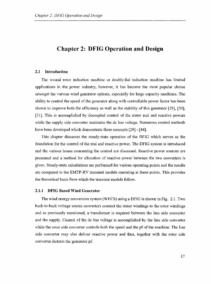
2.1.1 DFIG Based Wind Generator
The wind energy conversion system (WECS) using a DFlG is shown in Fig. 2.1. Two
back-to-back voltage source converters connect the stator windings to the rotor windings
and as previously mentioned, a transformer is required between the line side converter
and the supply. Control of the dc bus voltage is accomplished by the line side converter
while the rotor side converter controls both the speed and the pf of the machine. The line
side converter may also deliver reactive power and thus, together with the rotor si de
converter dictates the generator pf.
17

Chapter 2: DFIG Operation and Design
DFIG Gearbox
Fig. 2.1 DFIG wind energy conversion system
The ratings of each of the converters as well as of the generator itself must be respected and therefore, CUITent limits must be implemented in each of the two control algorithms as in [29]. The speed is limited as weIl in order to respect the mechanical limitations of the system. The surnrnary of the control objectives of the two converters as well as the machine are given be10w in Table 2.1.
Table 2.1 Control objectives for converters and DFIG-WECS
Regulate de bus Yes Yes No
18

Chapter 2: DFIG Operation and Design
2.1.2 Steady-State Equivalent Circuit
The induction machine can be represented by it steady-state equivalent circuit as is
given in aIl machine theory textbooks, such as [45]. It is presented in Fig. 2.2 in order to
develop the basis for decoupled control of Ps and Qs. From the equivalent circuit one can
derive the following equations which relate the steady-state quantities of the rotor and
stator sides.
(2.1)
If the stator si de voltage is used as the angle reference then the remainder of the
quantities can be defined assuming a fixed stator voltage magnitude and given the
required real and reactive power. From Ps and Qs, one can then define the magnitude and
phase of the cUITent, Is as follows:
P Re(i.) =_s
s V s
Im(i ) = _ Qs s V
s
(2.2)
(2.3)
Then using (2.1), the first and third row equations are used to find Ir, followed by the
second to find the required voltage applied at the rotor terminaIs. This apparently
elementary study forms the basis for transient control of the rotor side converter. Of
course there are various technicai issues related to synchronization of the various signaIs
and application of the necessary forward and reverse transformations, however, the
control algorithm follows from this simple analysis.
19

Chapter 2: DFIG Operation and Design
i)(' RJs N:1
+
V;sLor
Fig. 2.2 Wound rotor induction machine equivalent circuit
2.1.3 Wind Energy System Models
ln order to investigate the operation of a DFIG as a wind generator, all of the
necessary mode1s include realistic machine parameters, wind speed, input torque
characteristics, and the required protection settings are required. Accurate modeling of the
mechanical system is crucial especially in regards to the various time constants associated
with the wind turbine itse1f, the blades, and the pitch control. The mode1ing of these
components is discussed in detail in many of the literature and they will not be revisited
here. The machine parameters and basic wind mode1s are included in the Appendix for
the interested reader while greater details can be found in references [15].
2.2 Reactive Power Allocation
Reactive power control is an important issue, particularly in WECS which are
connected to weak networks. Voltage support capability is often required to maintain the
ac voltage within the limits of operation and improve recovery following disturbances and
is possible in MV networks when reactive power can be accurate1y controlled. The DFIG
is one type ofwind generator which has the ability to at the very least compensate for the
reactive power required by the induction machine. Various studies have shown that this
and other wind generators capable of reactive power control can improve the stability of
the system and its tolerance to disturbances [6], [18], [19].
20

Chapter 2: DFIG Operation and Design
(a) (b)
(c) (d)
Fig. 2.3 Reactive power options for wind generators (a) switched capacitors (b) SVC
(c) STATCOM (d) DFIG
2.2.1 Reactive Power Sources
One of the differences between squirre1 cage induction machines and synchronous
machines is that induction machines consume reactive power in aIl modes of operation
whereas for synchronous generators, the reactive power can be controlled to be leading or
lagging depending on whether the machine is over or under-excited. The DFIG possesses
the ability to control its power factor and additionally it is capable of supplying reactive
power from two separate sources: from the stator by control of the rotor si de converter or
from the suppl y side converter, in a manner analogous to a STATCOM. Since the
controls of these two converters are essentially decoupled, the reactive power can be
adjusted by independently adjusting the amount supplied from either of the two sources.
The combined VAr injection then determines the amount supplied to or absorbed from
the grid, Fig. 2.4.
21

Chapter 2: DFIG Operation and Design
Os ~ ..
GRID
Il Or Om
1~ 1~ ~ ..
Oconv
Fig. 2.4 Reactive power sources in the DFIG
2.2.2 Optimum Reactive Power Distribution
The manner in which the reactive power is allocated will result in different CUITent
magnitudes in the two converters and consequently, will affect their kVA ratings. Studies
performed by the author have shown that in order to minimize the combined CUITent
magnitude the majority of the reactive power should be supplied from the rotor side
converter, while approximate1y 20% is supplied from the suppl y side converter [46].
However, when generation is high and the real component of the machine CUITent is high,
the CUITent limits may curtail the reactive power supplied from the stator side and thus the
distribution becomes more equal. This allocation method is based on steady-state
considerations and therefore, the CUITent limits of two converters may cause discrepancies
under these extreme transient cases.
This section focuses on the de1egation of the reactive power compensation and
demonstrates that through proper division of the reactive power compensation between
the two converters, the overall rating of the two converters can be minimized. The
parameter, K will be refeITed to as the rotor side converter compensation constant and
will be defined as:
22

Chapter 2: DFIG Operation and Design
K = --=-Q-,-I' -QI' + Qconv
(2.4)
Where Qr and Qconv are defined as the reactive power injected into the machine from
the rotor side and the reactive power injected by the supply side converter, respectively,
Fig. 2.4. Note that the denominator represents the total reactive compensation supplied
because of the way Qconv has been defined. If the synchronously rotating frame is
considered, the reactive powers in (2.4) will be proportional to the currents irq and iconv,q.
The compensation constant will be chosen in order to minimize the combined complex
power of the rotor side and grid side converters.
2.2.2.1 Problem Definition
The greater of the two ratings was chosen as the minimizing function, since generally
in practice, the kV A ratings of the two converters should be matched. Matched converters
are typically standard and thus, a reduction in cost is possible if they are chosen to be
equal. Thus, the following function will be minimized:
(2.5)
Subject to the following constraints:
nmin :::;; n :::;; nmax (2.6)
i" il' satisfy (2.1), the steady-state equivalent circuit model (2.7)
Where n is the transformer tums ratio. The dc link voltage is chosen in order to ensure
control over the set speed range of 80 to 120% of synchronous speed. This implies that at
the maximum magnitude of slip, Smax, the machine will present an induced voltage, Vr,ind
on the rotor side of magnitude given by:
23

Chapter 2: DFIG Operation and Design
1 I
V, V/',ind =-
smax
(2.8)
The re1ationship between the line-to-line voltage and the dc voltage is approximately
given by:
(2.9)
Where, ma is the modulation index of the rotor side converter. Therefore, in order to
ensure control at the maximum magnitude of slip, and assuming the rotor side converter
operates in the linear modulation range with ma = 1, the dc voltage, Vdc is chosen using:
V = Smax V, de 0.612
(2.10)
The values of nmin and n max are chosen by assuming that the supply side converter
operates with a modulation index between 0.8 ~ ma ~ 1. Then, incorporating (2.9) into
(2.10) results in:
(2.11)
2.2.2.2 Optimum Allocation
The results of the optimization problem are summarized in Fig. 2.5. The maximum
rating of the two converters is p10tted over K for different values of the system reactive
power, Qgrid. This has been done assuming the generator is supplying its rated real power
(~ 0.92 pu). Only the case of slip = -20% is shown, the speed at which the maximum
converter currents results.
24

Chapter 2: DFIG Operation and Design
It can be noted that the majority of the compensation is supplied from the rotor side
converter (70-85%) however, a small percentage should come from the suppl y side
converter in order to minimize the maximum rating of the two VSCs. Considering only
the limiting case, when 0.8 pu is injected into the system (Qgrid = -0.8), it can be noted
that approximately 20% should be supplied from the line si de converter and thus, the
rating of the converter should based upon this value. It should also be noted that when
comparing the curves of ratings of the individual converters, they do in fact, become
equal at the minimum point as should be expected. This explains the discontinuity at this
point, as it is the intersection of these two curves.
0.7 ..
0.65
0) 0.5
C ........ 0.45 ro L- 0.4
::; 0.35
~ 0.3
0.25
0.2
. ~.
Ql Q2 Q3 0.4 Q5 Q6 0.7 0.8 Qg
Rotor compensation constant, K
Fig. 2.5 Maximum kVA ratings of converters as a function of the proportion of reactive
power supplied from rotor side converter
2.2.2.3 Comparison with Transient Model
Simulations in EMTP-RV were carried out to show that in fact a reduction in the kVA
rating is possible by sharing the reactive compensation between the two converters, Fig.
2.6. The kV As of the two converters were obtained for the limiting case of Qgrid = -0.8
while controlling the machine to 1.2 OJsyn (slip = -0.2). The complex powers are shown for
K = 1 and K = 0.8. In the latter case, it can be noted that the rating of the rotor side
25
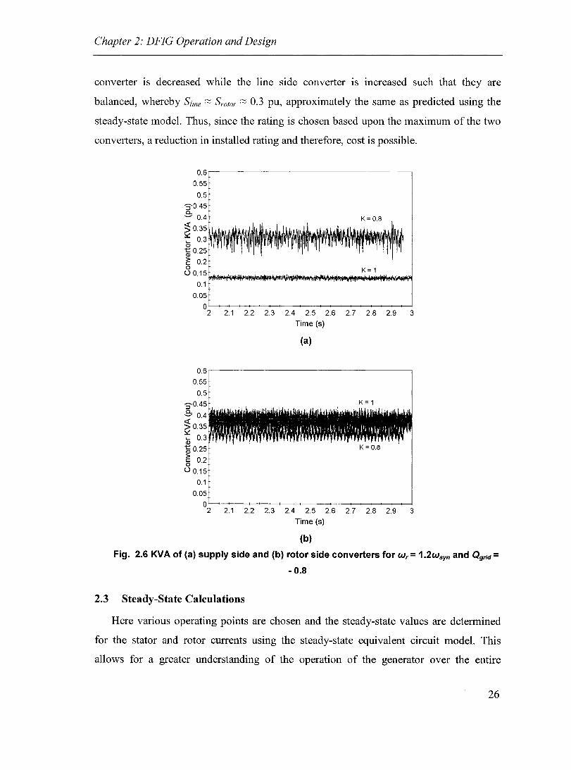
Chapter 2: DFIG Operation and Design
converter is decreased while the line side converter is increased such that they are
balanced, whereby Sline ;:::; Sr%r ;:::; 0.3 pu, approximately the same as predicted using the
steady-state model. Thus, since the rating is chosen based upon the maximum of the two
converters, a reduction in installed rating and therefore, cost is possible.
0.6'---~~~~~~~~~~~~~~~~-----,
0.55
0.5
'3'045 a. ~ 0.4 K= 0.8 :;; 0.35 ~ 0.3J11\1I\1I~II\II!lInll\ll1 <l)
~0.25
E 0.2
8 0.15*~~"'\!\_iIlW'I~._~r'JfiIN~~~K~=iII\I1~~W 0.1
0.05
O~~~~~--~~----~~~~--~--~ 2 2.1 2.2 2.3 24 2.5 2.6 2.7 2.8 2.9 3
Time (s)
(a)
0.6'--~~~~~~~~~~~~~~~~------,
0.55
0.5
'3'0.45
.3: 0.4
~0.35 ~ 45 0.3
~0.25 § 0.2 Ü 0.15
0.1
0.05
K= 1
K=0.8
O~~~~--~--------~~~~--~~~ 2 2.1 2.2 2.3 24 2.5 2.6 2.7 2.8 2.9 3
Time (s)
(b)
Fig. 2.6 KVA of (a) supply side and (b) rotor side converters for W r = 1.2wsyn and Qgrid = - 0.8
2.3 Steady-State Calculations
Here various operating points are chosen and the steady-state values are determined
for the stator and rotor currents using the steady-state equivalent circuit model. This
allows for a greater understanding of the operation of the generator over the entire
26

Chapter 2: DFIG Operation and Design
operating range. In order to perfonn the calculations, the following quantities are first
specified: the rotor speed, OJr, the power delivered to the grid, P gtid, and the reactive power
supplied to the grid, Qgtid. Then the remaining quantities can be calculated in steady-state
assuming the voltage at the PCC is 1 pu. The reactive power is divided between the two
sources as previously mentioned.
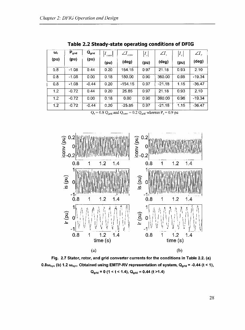
Using the same machine parameters as ln the transient models, the results for
operation with leading, lagging, and unit y power factor operation at super and
subsynchronous speeds are obtained. The results are shown in Table 2.2. The same list of
operating characteristics is then obtained using the transient model developed in EMTP
RV (discussed in detail in chapter 3). It can be noted that the transient wavefonns roughly
match the values obtained using the steady-state calculations, supporting the calculations
but also the validity of the transient models.
27
Chapter 2: DFIG Operation and Design
W r
(pu)
0.8
0.8
0.8
1.2
1.2
1.2
Table 2.2 Steady-state operating conditions of DFIG
Pgrid Qgrid IIconv 1 L.lconv 11,1 L.I, 11,.1 L.I,. (pu) (pu)
(pu) (deg) (pu) (deg) (pu) (deg)
-1.08 0.44 0.20 154.15 0.97 21.18 0.93 2.10
-1.08 0.00 0.18 180.00 0.90 360.00 0.98 -19.34
-1.08 -0.44 0.20 -154.15 0.97 -21.18 1.15 -36.47
-0.72 0.44 0.20 25.85 0.97 21.18 0.93 2.10
-0.72 0.00 0.18 0.00 0.90 360.00 0.98 -19.34
-0.72 -0.44 0.20 -25.85 0.97 -21.18 1.15 -36.47
Qs = 0.8 Qgrid and Qconv = 0.2 Qgrid whereas P s = 0.9 pu
:;-0.2 0.. ---> 0 c o .2-0.2
0.8 1
1 1.2 1.4
-1~--~--~--~~~ 0.8 1 1.2 1.4
1
-1 ~--~--~--~~~
0.8 1 1.2 1.4 time (8)
(a)
.-::J 0.. ---.~
0.8 1 1.2 1.4 1
-1~--~--~--~--~ 0.8 1 1.2 1.4
1
1 1.2 1.4 time (8)
(b)
Fig. 2.7 Stator, rotor, and grid converter currents for the conditions in Table 2.2. (a)
0.8wsyn (b) 1.2 w syn• Obtained using EMTP-RV representation of system, Qgrld = -0.44 (t < 1),
Qgrid = 0 (1 < t < 1.4), Qgrld = 0.44 (t >1.4)
28

Chapter 2: DFIG Operation and Design
2.4 Conclusions
In this chapter the steady-state models of the DFIG - WECS have been introduced.
The various sources of real and reactive power were presented and the control goals along
with the fundamental basis for deve10pment of the algorithm were given. Reactive power
is an important issue and the DFIG is able to control the reactive power from two sources.
It is shown that the majority of reactive power should be supplied from the rotor side
converter in order to reduce the overall kVA rating of the two converters. Comparison of
steady-state calculations with the transient models shows good agreement. Small
discrepancies result from the simplifications made when using the transformer equivalent
circuit while the EMTP-RV model utilizes the full state space representation of the
system. The instantaneous control of the DFIG can now be deve10ped following the
principles outlined in this chapter.
29

Chapter 3: Transient Models and Control
Chapter 3: Transient Models and Control
3.1 Introduction
The control of the DFIG consists of two separate control algorithms, which together
realize the overall function of the system. Through appropriate modulation of the rotor
side converter, decoupled control of Ps and Qs is possible. The supply side control is
responsible for regulating the dc bus voltage and thereby facilitates the flow of rotor
power either to or from the machine, depending on the sign of the slip. Higher-Ieve1
controls select the real and reactive power references in order to control the speed of the
machine and regulate the ac voltage, respectively. The controls are demonstrated using
EMTP-RV. As a means ofverifying the representation, a similar representation is built in
MATLAB - SimPowerSystems and the results are compared.
3.2 Converter Controls
As mentioned, the two converters are controlled separately using two separate control
algorithms. The rotor side control was deve10ped using the steady-state equivalent circuit
with PI compensation, however closely resembles the control structures discussed in
[30],[39] ,[44]. The line si de control follows from STATCOM or rectifier control theory
and will not be presented in depth.
3.2.1 Current Control
CUITent control techniques using an inverter can be grouped into two main classes: (i)
pulse-width modulation (PWM) based linear feedback control and (ii) hysteresis control.
A third category could include the numerous nonlinear control techniques, however, they
were not implemented in this case and thus will not be discussed further.
30

Chapter 3: Transient Models and Control
3.2.1.1 PWM Linear Feedback Control
In this control structure, the three phase currents are decomposed into their d and q
components. These components are compared with the reference signal and the error
signal is passed through a proportional integral (PI) or other linear compensator block,
whose output generates the d and q components of the modulating signaIs. A feedforward
signal may be included which can in sorne cases improve the transient response, Fig. 3.1.
abc to dq
id,ref -jlJ e
Fig. 3.1 PWM linear feedback current control structure
3.2.1.2 Hysteresis Current Control
In hysteresis current control, a small hysteresis band is added to the reference signal
Fig. 3.2. The gating signaIs are then chosen based upon the required slope of the
instantaneous line currents. In this way, the current remains within the band. Drawbacks
of this method include unpredictable switching frequency (making tuning of filtering
components difficult) and increased switch stresses, however, the control is very precise.
31

Chapter 3: Transient Models and Control
______ ~ (1) i >= iref + iband
Then di/dt < 0 iref
---r-_____ ++t--~ (2) i <= iref - iband
+
Then di/dt> 0 (3) iref - iband < i < iref + iband
Then di/dt = di/dt (k-1)
o
iref - iband
+
Fig. 3.2 Hysteresis current control structure and principle
3.2.2 Real and Reactive Power Control
The real and reactive power control of the stator is realized by the control of the rotor
side currents. In effect, Ps and Qs are first related to the rotor currents and then the rotor
currents are controlled through the appropriate gating of the rotor converter. Since control
is accompli shed on the synchronously rotating frame, this requires both the rotor angle
and suppl y voltage angle for synchronization.
The sequence of the control is outlined here:
a) Measure all required quantities including stator voltages, rotor and stator currents,
rotor angle
b) Extract the voltage angle using a phase-Iocked loop (PLL)
c) Perform the appropriate transformations to express all voltage and current
quantities on the synchronously rotating frame
d) Calculation of Ps and Qs
32

Chapter 3: Transient Models and Control
e) Generate the rotor CUITent references using the output ofthe output PI
compensator outputs
f) Rotor CUITent control using PI compensators for d and q components and the
feedforward terms based upon the steady-state equivalent circuit.
g) Transform the rotor voltage back to rotor side abc quantities
h) Modulation of the rotor voltages for generation of the gating signaIs
The control algorithm is represented in block diagram form in Fig. 3.3.
GRID
Supply Side Converter
1-------( >-----,-----\ rv
e-j(1J - 9r)
Vrq,ff irq,ref ird,ref
Feed-Forward Terms
RotorSide Converter
ei(1J - 9r)
DFIG
pa Calculation
Ps,ref
Speed Control
Fig. 3.3 Rotor side converter control algorithm for control of Ps and Qs
In Fig. 3.3, the rotor angle and speed are shown to be measured using an encoder,
however, these quantities can be estimated, thereby making the control sensorless, in that
only electrical transducers are required. This type of sensorless control was utilized,
following the work done in [39].
33
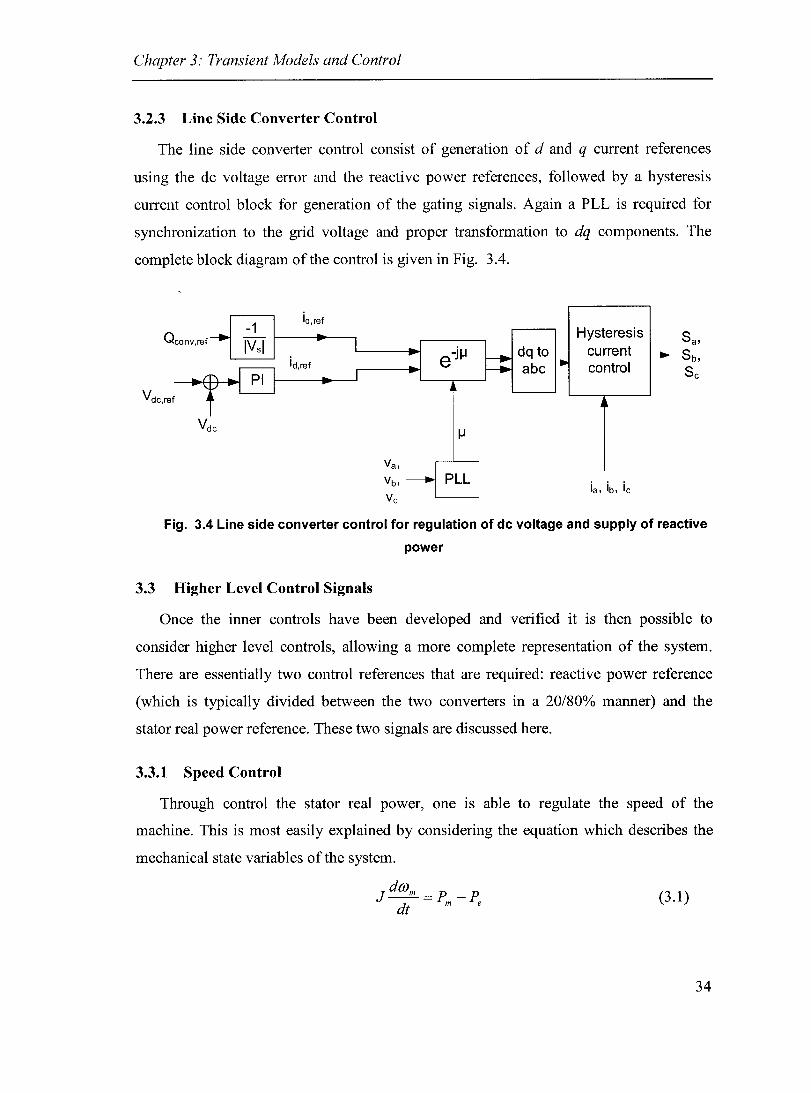
Chapter 3: Transient Models and Control
3.2.3 Line Side Converter Control
The line side converter control consist of generation of d and q current references
using the dc voltage error and the reactive power references, followed by a hysteresis
current control block for generation of the gating signaIs. Again a PLL is required for
synchronization to the grid voltage and proper transformation to dq components. The
complete block diagram of the control is given in Fig. 3.4.
iq,ref
Qconv,ref
Vdc,ref
-j IJ e dq to abc
Hysteresis current control
Fig. 3.4 Une side converter control for regulation of dc voltage and supply of reactive
power
3.3 Higher Level Control Signais
Once the inner controls have been developed and verified it is then possible to
consider higher level controls, allowing a more complete representation of the system.
There are essentially two control references that are required: reactive power reference
(which is typically divided between the two converters in a 20/80% manner) and the
stator real power reference. These two signaIs are discussed here.
3.3.1 Speed Control
Through control the stator real power, one is able to regulate the speed of the
machine. This is most easily explained by considering the equation which describes the
mechanical state variables of the system.
J dOJm = p -p dt m e
(3.1)
34

Chapter 3: Transient Models and Control
Here, it can be noted that if there is an imbalance between Pm and P e then the machine
will either accelerate or decelerate. Therefore, by setting Ps, the speed of the machine can
be regulated. Once the set speed has been reached, Ps automatically adjusts Pe = Pm and
the speed remains constant. The block diagram for the speed control is given in Fig. 3.5.
The speed reference is typically chosen in order to track the optimum power capture
points, which vary as the wind speed changes [30], [43]. Once the rating of the machine
has been reached, the pitch control is then used to limit the stator power to this value.
Vwind Peak Wnn,ref + Power 1 1 point 1
PI 1 -
tracking
Ps,ref [3
Fig. 3.5 Speed controlloop for generation of Ps,ref
3.3.2 Ac Voltage Regulation
The fluctuations in the ac voltage at the PCC depend upon the flows along the line,
which are dependent upon both P and Q. However, in cases where the XlR of the line is
large, the terminal voltage can be controlled through management of the reactive power at
the terminal bus. The basic concepts of reactive compensation are discussed in [47].
In squirrel cage generators, the machines consume reactive power irregardless of the
state of operation. Typically, capacitor compensation is used at the PCC in order to bring
up the voltage, however, this solution offers no ability to change the reactive power
delivered, with the exception of switching the banks in and out, with limited usefulness
under transient conditions.
The DFIG has two sources of reactive power and therefore, not only can the internaI
reactive power requirement be met but it is also possible to supply reactive power in order
to support the voltage at the PCC. Therefore, the reactive power reference is chosen based
upon the difference between the ac voltage magnitude and the reference Fig. 3.6. A 1-3%
droop has been incorporated in order to promote sharing of the compensation between
DFIGs connected in parallel.
35

Chapter 3: Transient Models and Control
1-K ... Vref Qconv
Q ± V rel .rT\ PI t • ." V Q K
K
Fig. 3.6 Generation of the reactive power reference for support of ac voltage, (K = 0.8
in most cases)
3.4 Control Verification
The DFIG system was developed in EMTP-RV since it enables representation of a
system with numerous nodes and therefore, facilitates system level studies while still
using the transient model. In order to present a means of verification, the simulation
results were compared with an average mode1 representation in MA TLAB -
SimPowerSystems. This was meant as a comparison only and the intent was only to
support the control results since SimPowerSystems is not as well suited for simulation of
large systems.
3.4.1 Decoupled Control of Ps and Qs
Here, the rotor si de control was tested, subjecting the control to step changes in real
and reactive power references. As can be noted the control responds quite well, however,
it is not completely decoupled as is to be expected. The existence of losses in the machine
and the magnetizing branch account for the resulting change in the real power as the
reactive power is changed. The coupling is limited and the control function is satisfactory.
The SimPowerSystem mode1 performs less well and the step change in Q used is
smaller, however, exhibits somewhat similar response in terms of a slight coupling
between P and Q. Tuning of the control parameters was not possible as the model was an
example within the software and access to these variables was limited.
36

Chapter 3: Transient Models and Control
1.5
1\ _.t.
1W r- I ~ :::J
E: v ,. -Cf)
a.. 0.5
~.5 1.5 2 time (5)
0.5 ft.
s-E: Cf)
0 a
---0.5 v
1.5 2 time (5)
(a)
1.5,--------...,--------,---------,
0.5
8.5 1.5 2 lime (5)
0.5
:::J
S 0 en a
-0.5
-Ù.~5-------~------~1~.5------~2
time(5)
(h)
Fig. 3.7 Step response for Ps and Qs using (a) EMTP-RV (b) MATLAB
SimPowerSystems
37

Chapter 3.' Transient Models and Control
3.4.2 Speed Control
The control of the DFIG must be able to change the speed of the machine, in order to
track the peak power points but also to limit the output power in sorne cases. Therefore,
the speed control was verified by varying the generator speed over the speed range:
O.9wsyn to 1.1wsyn, Fig. 3.8. As can be noted the generator follows weIl the intended
trajectory and the frequency of the rotor currents goes to dc as the generator passes
through synchronous speed. The SimPowerSystems model did not possess electrical
speed control however upon variation of the input torque the variations in rotor frequency
were obtained. Since the model is an average model it lacks the harmonics of the EMTP
RV case but fundamental frequency components are similar.
38
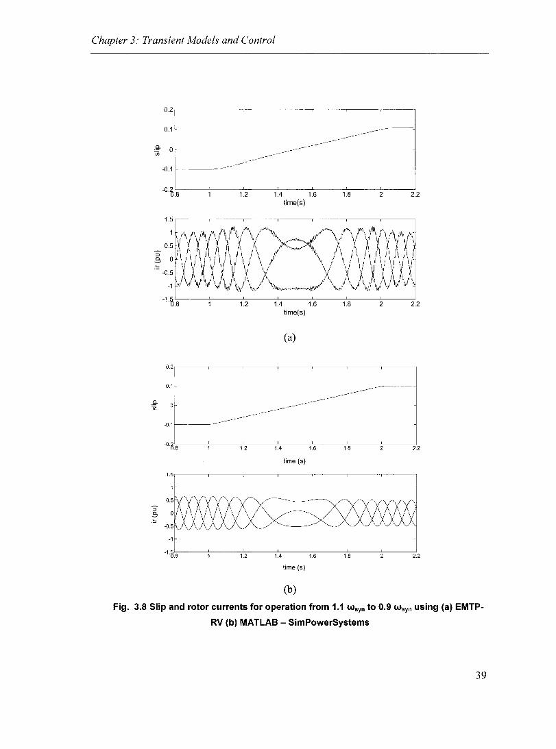
Chapter 3: Transient Models and Control
0.2,-------,-------r-----,--
0.1
,g- 0 Cf)
-0.1 f-----------
-0.2 0.8 1.2 1.4 1.6
time(s)
....
-1
1.2 1.4 1.6 time(s)
(a)
0.2
0.1
.9-en
-0.1
-0.0.8 1.2 1.4 1.6
lime (5)
1.5
-1
1.8 2 2.2
1.8 2 2.2
1.8 2 2.2
-1·8.':"s -----:--------:1""=".2------=-'1.4-:-------:1c':::.6------=-"1.-=-S -----=-2------::"2.2
lime (5)
(b)
Fig. 3.8 Slip and rotor currents for operation from 1.1 wsyn to 0.9 wsyn using (a) EMTP
RV (b) MATLAB - SimPowerSystems
39
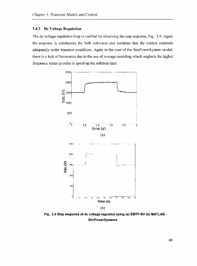
Chapter 3: Transient Models and Control
3.4.3 De Voltage Regulation
The dc voltage regulation loop is verified by observing the step response, Fig. 3.9. Again
the response is satisfactory for both softwares and confirms that the control responds
adequately under transient conditions. Again in the case of the SimPowerSystem model,
there is a lack ofharmonics due to the use of average modeling which neglects the higher
frequency terms in order to speed up the solution time.
2500.-----~--.----~--~----,
2000
---> 15001---~ L .........
C,,) "C
> 1000
500
°1~-~1~.2---1~.4~-~1.~6--~1.~8--~2
time (s)
(a)
2500
2000 r--
~ 1500 1..---
CJ
" > 1000
500
1~ 12 13 lA I~ lB I~ lB lB
time (s)
(b)
Fig. 3.9 Step response of de voltage regulator using (a) EMTP-RV (b) MATLAB
SimPowerSystems
40

Chapter 3: Transient Models and Control
3.5 Conclusions
In this chapter, the transient control models have been presented and were verified
using numerical simulations. The rotor si de and stator side control models, which are both
based upon inner current loops with outer loops for generation of the CUITent references,
were tested using both EMTP-RV and MATLAB - SimPowerSystems. The control
verification shows that the various control algorithms function as they should in all cases.
In addition, the SimPowerSystem simulations supported the results obtained in EMTP
RV, with similar results, where the inconsistencies are explained by the model
development differences (EMTP-RV being full transient model while SimPowerSystems
being an average model).
It should be noted that the cases tested were artificially generated and transients
occurring in the power systems may result in different responses due to conditions to
which the system has not been subjected here, such as inability to accurately measure the
system frequency and voltage or supply unbalances. In summary, the control verification
has shown that the control principles are reasonable, however, once connected to a
realistic power system, which is subjected to typical disturbances, the performance may
differ somewhat.
41

Chapter 4: Integration of Energy Storage
Chapter 4: Integration of Energy Storage
4.1 Introduction
The main drawback associated with wind energy, other than its relatively high
installation cost, is the fluctuation of its output power as a result of variations in the wind
speed. The DFIG can be used to smooth the output power by simply varying the torque
characteristics, using a combination of pitch control and variation of the generator speed,
with the end goal of regulating the supplied power. This is a technique commonly
employed by wind turbine manufacturers such as VESTAS and GE-Wind. However, this
requires operation at suboptimal points and therefore, a significant portion of the potential
power capture is wasted in order to schedule more accurately the generator output power.
Furthermore, it is only applicable at or above rated wind speeds and therefore, cannot
help during low wind conditions.
The use of the generator inertia to regulate the output power is relevant at higher wind
speeds when the output power approaches the rated value of the machine. In this case, the
generator is temporarily storing energy in the inertia of the rotating mass. When the
mechanical input power exceeds the required output, the generator speeds up and stores
energy, which is later released when the input power falls below the reference. Therefore,
the generator functions similar to a flywheel in this respect in order to regulate the output
power. This action, combined with pitch control to reduce the input torque at higher wind
speeds, allows sorne amount of power regulation.
The addition of energy storage has been considered for wind energy applications but
its implementation has been slowed by the high cost. It has been shown that energy
storage is capable of aiding in the regulation of the wind generator output power [50],
[52], [53], however, the implications of this design choice have not been investigated in
detail. Instead, these studies have focused mainly upon the technical requirements and
have failed to address the issues of energy management and the added performance of
42
Chapter 4: Integration of Energy Storage
wind generator. Integration of energy storage to DFIGs and induction generators have
been presented in [54] and [55], respectively, however, further studies are still necessary.
In the present work, the basis for incorporation of super-capacitors into a DFIG is
considered. A method of rating the energy storage element is provided and the controls
for normal operation and operation at the limits are presented. This topology possesses
the advantage that each of the wind turbines has its own energy storage, and therefore, it
could be argued that the overall reliability of the system is improved compared with
centralized energy storage. This is due to the fact that when a single generator is
unavailable, the energy storage capability of the system and consequently the ability to
dispatch a required amount of power is not lost.
·4.2 Energy Storage System
Introduction of energy storage into the design adds another degree of complexity and
the control is modified in order to account for the different modes of operation. Under
normal operation energy is exchanged with the system based upon the system
requirements: energy is stored when there is excess generation and is supplied when the
output power drops below the reference level. However, it is necessary to consider the
case when the storage element has reached either its upper or lower limit.
The control must be modified once the energy storage has completely supplied all of
its energy or it is saturated, i.e. it has stored its total capacity. In this case, the DFIG is
controlled as though the energy storage is no longer available and again the output power
reflects the variations in the wind. In addition, the control must then detect when to revert
back to normal operation in order to once again take advantage of the ESS. Furthermore,
the maximum amount of power that the device may store or supply should be considered,
however, this can be done indirectly through the CUITent limit of the line si de converter.
Table 4.1 summarizes the considerations for the ESS control during the different modes
of operation.
43

Chapter 4: Integration of Energy Storage
Table 4.1 Energy storage system control for normal and limiting
operation
Enerliy/~ti!'I'etl Operdtio,n Error signal Transfer of control , "), :::1>;/' ';\) >,,""
Upper limit Pgrid = 0.95 Pref
Lower limit P grid = 1.05 Pref
4.2.1 DFIG and ESS System and Rating
Through addition of energy storage in the dc bus, the hne si de converter can serve as
either a source or sink of real power. The ESS may be either directly connected across the
dc bus or altematively it may be interfaced with the bus using a de/dc converter. Fig. 4.1
shows the block diagram of the case where the ESS (in this case supercapacitors) is
connected to the dc bus using a 2-quadrant dcl dc converter as is used in [48]. For this
topology, the ESS regulates the dc voltage via the chopper while the line side converter
regulates the generator output power.
Pgrid Ps Pr Pess .-- .-- ---+ .-- ---+
if' .--
Pconv ! l Super-capacitor
$~
Fig. 4.1 Energy storage interfaeed with de bus using de/de eonverter
In this arrangement, the voltage across the ESS would vary between roughly 0 and
100% of V de, depending on the amount of energy stored. Once the voltage reaches one of
the boundaries, the storage device becomes either saturated or exhausted and the control
must be modified.
44
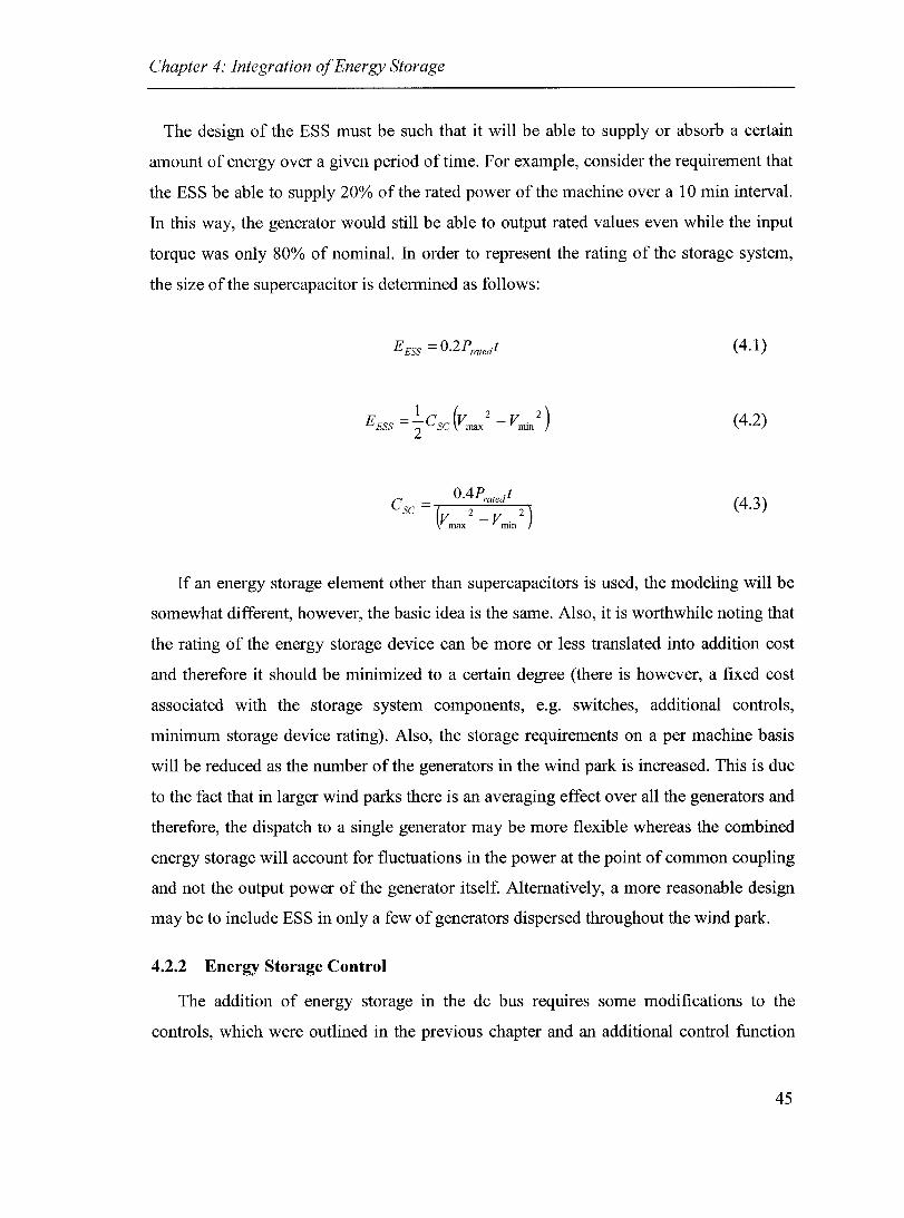
Chapter 4: Integration of Energy Storage
The design of the ESS must be such that it will be able to supply or absorb a certain
amount of energy over a given period oftime. For example, consider the requirement that
the ESS be able to supply 20% of the rated power of the machine over a 10 min interval.
In this way, the generator would still be able to output rated values even while the input
torque was only 80% of nominal. In order to represent the rating of the storage system,
the size ofthe supercapacitor is determined as follows:
E ESS = O.2Prated t (4.1)
1 (2 2) E ESS = le sc Vmax - ~nin (4.2)
(4.3)
If an energy storage element other than supercapacitors is used, the modeling will be
somewhat different, however, the basic idea is the same. AIso, it is worthwhile noting that
the rating of the energy storage device can be more or less translated into addition cost
and therefore it should be minimized to a certain degree (there is however, a fixed cost
associated with the storage system components, e.g. switches, additional controls,
minimum storage device rating). AIso, the storage requirements on a per machine basis
will be reduced as the number of the generators in the wind park is increased. This is due
to the fact that in larger wind parks there is an averaging effect over aIl the generators and
therefore, the dispatch to a single generator may be more flexible whereas the combined
energy storage will account for fluctuations in the power at the point of common coupling
and not the output power of the generator itself. Altemative1y, a more reasonable design
may be to inc1ude ESS in only a few of generators dispersed throughout the wind park.
4.2.2 Energy Storage Control
The addition of energy storage in the dc bus requires sorne modifications to the
controls, which were outlined in the previous chapter and an additional control function
45
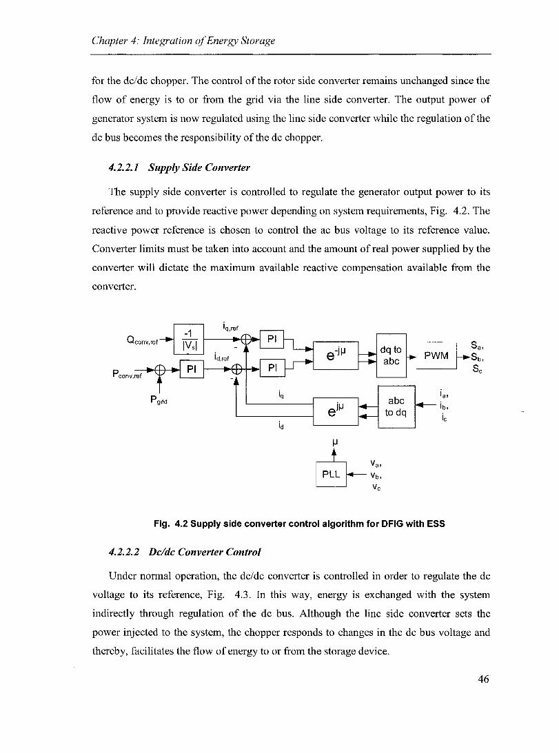
Chapter 4: Integration of Energy Storage
for the dc/dc chopper. The control ofthe rotor side converter remains unchanged since the
flow of energy is to or from the grid via the line si de converter. The output power of
generator system is now regulated using the line side converter while the regulation of the
dc bus becomes the responsibility of the dc chopper.
4.2.2.1 Supply Side Converter
The supply side converter is controlled to regulate the generator output power to its
reference and to provide reactive power depending on system requirements, Fig. 4.2. The
reactive power reference is chosen to control the ac bus voltage to its reference value.
Converter limits must be taken into account and the amount of real power supplied by the
converter will dictate the maximum available reactive compensation available from the
converter.
Qeonv,ref
-j IJ dq to Sa, e abc Sb,
Sc Peonv,ref
P9rid iq ia,
e jlJ ib,
ie id
IJ
&v" PLL Yb, Ve
Fig. 4.2 Supply side converter control algorithm for DFIG with ESS
4.2.2.2 De/de Converter Control
Under normal operation, the dc/dc converter is controlled in order to regulate the dc
voltage to its reference, Fig. 4.3. In this way, energy is exchanged with the system
indirectly through regulation of the dc bus. Although the line side converter sets the
power injected to the system, the chopper responds to changes in the dc bus voltage and
thereby, facilitates the flow of energy to or from the storage device.
46

Chapter 4: Integration of Energy Storage
ln range detector Supercapacitor-----..
Voltage Vess,min <= Vsc <= Vess,max
Gating signais
If outside range
signais blocked
Fig. 4.3 Dc/dc converter control for regulation of dc bus and supplementary control for
detection of limits
4.2.3 Energy Storage Limitations
The control of the DFIG system is unchanged with regards to the rotor si de converter
as a result of the addition of the ESS, whereas the supply side converter control enables
the transfer of energy to or from the storage device. The line side converter control is
modified in order to regulate the power supplied to the grid, P grid. Then the regulation of
the dc bus voltage is accompli shed by the de/dc converter, and in this way energy is
exchanged between the grid and the storage device.
However, due to abnorrnal wind speeds such as particularly storrny or calm
conditions, the ESS may reach either its maximum storage capability or become
completely discharged. Under these conditions, the control of the line side converter and
the de/dc converter must be modified.
First, the detection of the limiting condition is necessary, which can be accomplished
simply by monitoring of the ESS dc voltage. Once either the upper or lower limit is
reached the control of the two converters of interest change. The line side converter
becomes the dc-voltage regulator, the feedback signal and reference switching from the
generator powers to the dc voltage. The gating signaIs to the de/dc converter are then
blocked and the ESS is essentially disconnected from the system.
47

Chapter 4: Integration of Energy Storage
The condition to change back to the nonnal control algorithms is detected using the
voltage across the ESS and by monitoring the signal:
(4.4)
Ifthe expression in (4.4) is > 0 it suggests that energy could be stored and therefore if
VEss = Vess,min then the ESS control should be reactivated. On the other hand if (4.4) is < 0
and V ESS = Vess,max then the ESS control should be enabled such that energy is injected into
the system. In this way, the state of the ESS is constantly monitored and transfer between
nonnal and contingency operation is possible. In order to prevent oscillations between the
two states of operation, a small hysteresis band is introduced such that the conditions to
switch back to ESS control become the following:
V ess = Vess,min and Pgrid ~ 1.05Pgrid ,rel (4.5)
V ess = Vess,max and Pgrid ::::; O.95Pgrid ,rel (4.6)
The actual size of the bands could be adjusted based upon specific requirements, they
have been chosen arbitrarily as 5% above only to convey the concept. The block diagram
representation ofthe energy management is shown in Fig. 4.4.
48

Chapter 4: Integration of Energy Storage
Pgrid<= 1.05 Pgrid,ref
V ess <= Vess,min
P grid <= 0.95 P grid,ref
V ess >= Vess,max
+ P ---..1-++------, grid,ref - t
P grid
Vdc
Input Selector
{ °1 if Normal Operation
Limiting Operation
Bloek de/de gating signais if 1
id,conv,ref
Fig. 4.4 Control algorithm to transfer control between different states of operation
4.3 System Characteristics
The benefits of energy storage are demonstrated in the following section. Here the
DFIG and DFIG and ESS systems are compared to show how energy storage enables a
much greater control over the output power profile compared with the more conventional
case. The DFIG system is simulated using two control schemes: (i) tracking of the peak
power points and (ii) limited output power regulation using combined inertia and pitch
control. Here, the results are shown for a single generator only whereas the multiple
machine case is considered in Chapter 5.
The test system used in this study consists of a single machine connected to the
Thevenin equivalent representation of the grid. In order to highlight the need for reactive
power, the short circuit ratio (SCR) of the system is set to 6, characteristic of a weak
system. The reactive power reference is set in order to regulate the grid voltage using a
3% droop characteristic.
49

Chapter 4: Integration of Energy Storage
4.3.1 Normal Operating Characteristics
During nonnal operation, the line si de converter functions as the power regulator and
he1ps the DFIG to supply the required amount of power. In this way, the wind generator is
able to capture the maximum amount of power and at the same time deliver the
dispatched power to the grid. In addition, this is no way interferes with the reactive power
control of the generator, which continues to be decoupled from the real component and
can be used to he1p support the grid voltage.
Fig. 4.5 and Fig. 4.6 show the real and reactive power flows for the cases of the
DFIG with and without energy storage, respective1y. As can be noted the DFIG is able to
supply 0.9 pu of real power over the entire 50 second interval in the case where energy
storage is used. In the case without energy storage the output power fluctuates with the
changes in the wind. The reactive power flows are decoupled from the real power,
however, slight discrepancies between the reactive power flows can be noted in the two
cases. This can be explained by the fact that the real power flows play a role in the change
in the tenninal voltage. As the reactive power reference is chosen in order to regulate the
ac bus voltage it is no surprise that Q is highly variable in the case without energy storage
whereas it is fairly constant in the case with ESS.
50

Chapter 4: Integration of Energy Storage
1.5
-.. :::l c... ~0.5
5
1.5
--:::l c... ~0.5
o
5 10 15
Ps-------..
pgrid/
Peonv~
25 30
time (s) (a)
Peon,
20 25 30
time (s) (b)
35
35
40 45 50
40 45 50
Fig. 4.5 Power flows for DFIG (a) with and (b) without energy storage
0.2
0.1 Qeonv
-0.2
5 10 15 20 25 30 35 40 45 50 time (s)
(a)
0.2
0.1 Qeonv Qs -- \ :::l E;o °_0.1
25 30 35 time (s)
(b)
Fig. 4.6 Reactive power flows for DFIG (a) with and (b) without energy storage
51
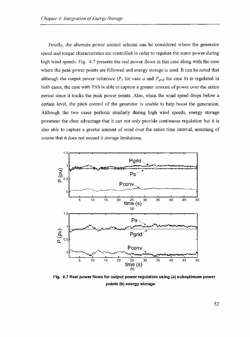
Chapter 4: Integration of Energy Storage
Finally, the altemate power control scheme can be considered where the generator
speed and torque characteristics are controlled in order to regulate the stator power during
high wind speeds. Fig. 4.7 presents the real power flows in this case along with the case
where the peak power points are followed and energy storage is used. It can be noted that
although the output power reference (Ps for case a and P grid for case b) is regulated in
both cases, the case with ESS is able to capture a greater amount of power over the entire
period since it tracks the peak power points. AIso, when the wind speed drops below a
certain level, the pitch control of the generator is unable to help boost the generation.
Although the two cases perforrn similarly during high wind speeds, energy storage
possesses the clear advantage that it can not only provide continuous regulation but it is
also able to capture a greater amount of wind over the entire time interval, assuming of
course that it does not exceed it storage limitations.
...-. ::J Cl. --
1.5
0... 0.5
...-. ::J Cl. --
o
0... 0.5
~ ~
V"
-5 10 15
5 10 15
Pgri~
PS/
Pcon~
. 20 25 30
time (S) (a)
Ps~
20 25 30 time (S)
(b)
"""'--V'-'~
. 35 40 45 50
35 40 45 50
Fig. 4.7 Real power flows for output power regulation using (a) suboptimum power
points (b) energy storage
52

Chapter 4: Integration of Energy Storage
4.3.2 Contingency Operating Characteristics
Although energy storage improves the ability to dispatch the wind generator, it cannot
realistically accomplish this feat at aIl times, due to the fact that the ESS has a finite limit
to both store and provide power. Therefore, the ability of the control to handle these
conditions as weIl as to be able to transfer control back to normal operation must be
verified. To accomplish this, the rating of the energy storage is reduced, thus causing it to
reach its limits with greater frequency. Altematively, the system could be tested using
long periods of low wind speeds followed by long periods of high wind speed, however,
it was deemed preferable to demonstrate both cases together and therefore, the former of
the two procedures was chosen.
Following reduction of the supercapacitor rating to 5%, the simulation was repeated to
verify that energy management control could successfully handle the limiting conditions.
Fig. 4.8 shows the response of the system when the energy storage rating has been
reduced. Here both the ESS voltage and grid power have been normalized in order to
present the results on the same axis.
As can be noted, the system fails to achieve the reference output of 0.9 pu when either
the upper or lower limitation of ESS is reached. At this point, dc regulation control is
transferred to the line side converter and the power exported to the grid then fluctuates
with the wind speed. Once the condition to reactivate the ESS is received, the line side
converter again regulates the output power to the specified reference. This confirms that
the system is not only able to handle these extraneous conditions but is also able to
transfer back to normal operation.
53
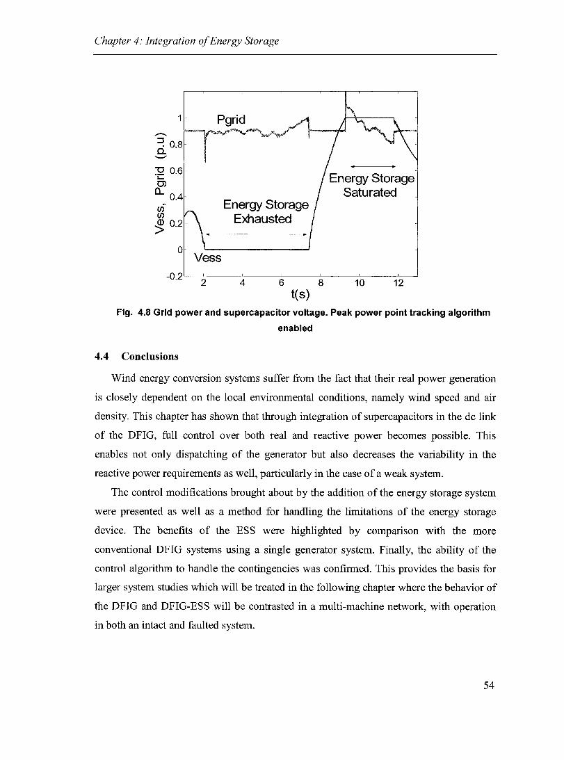
Chapter 4: Integration of Energy Storage
1
.-~ 0.8 a.
:g 0.6 ~
0> a.. 0.4 CI) CI)
~ 0.2
o Vess
Energy Storage Exhausted
Energy Storage Saturated
-0.2 '---2'-----4'-----6-'---------8-'-----1~0---1~2-----'
t(s)
Fig. 4.8 Grid power and supercapacitor voltage. Peak power point tracking algorithm
enabled
4.4 Conclusions
Wind energy conversion systems suffer from the fact that their real power generation
is c10sely dependent on the local environmental conditions, namely wind speed and air
density. This chapter has shown that through integration of supercapacitors in the dc link
of the DFlG, full control over both real and reactive power becomes possible. This
enables not only dispatching of the generator but also decreases the variability in the
reactive power requirements as well, particularly in the case of a weak system.
The control modifications brought about by the addition of the energy storage system
were presented as well as a method for handling the limitations of the energy storage
device. The benefits of the ESS were highlighted by comparison with the more
conventional DFlG systems using a single generator system. Finally, the ability of the
control algorithm to handle the contingencies was confirmed. This provides the basis for
larger system studies which will be treated in the following chapter where the behavior of
the DFlG and DFlG-ESS will be contrasted in a multi-machine network, with operation
in both an intact and faulted system.
54

Chapter 5: Grid Interconnection of DFIGs
Chapter 5: Grid Interconnection of DFIGs
5.1 Introduction
The impact of the interconnection of wind generation on the power system is of the
greatest interest from a utility perspective but also for the advocates of wind energy.
Transient simulations of high penetration wind energy systems can be used to propose
and test new technologies and methods that limit the disadvantages of wind, thereby
indirectly promoting its growth. The limiting factors to the increased growth of wind
energy technologies are technical as well as economic and political, and an improvement
in any of these areas will aid in the acceptance and further development of wind power.
Rere the proposed DFIG-ESS system is compared on a system level with the
conventional DFIG topology. Transient models of the two wind parks with identical
ratings are compared for a power system interconnection representative of a weak system.
The performance under normal operation as well as in response to a variety of potential
contingencies is considered.
5.2 Wind Park Interconnection
The wind park is connected to a 50 km, MV feeder that is in tum fed from a high
voltage (RV) transmission system via a 69/230 kV transformer, Fig. 5.1. The dual
transmission line also serves a local PQ load. The total installed capacity of the wind park
is 40 MW while its reactive power capability is rated at 0.5 pu or ±20 MV Ar.
The wind farm itself is composed of four turbines, each represented us mg the
transient models developed in the previous chapters. Aggregated models were used
assuming that each grouping of 10 turbines is subjected to identical wind conditions,
whereas the wind speed experienced by the neighboring aggregated turbines uses the
same wind data only delayed by 5 seconds. In this way, the averaging effect can be
observed while maintaining a reasonable length of simulation time.
55

Chapter 5: Grid Interconnection of DFIGs
Vwind1 ~ --+ HI Vwind2 L -~ jl
~~I VWind4 ==( --.J
--+~I
MV
50 km, 69 kV line
40 MW capacity DFIG wind park
HV
20 MW Load 0.97 pf
100 km, 230 kV dualline
Fig. 5.1 Interconnection of small wind farm with power system for transient system
level studies
The wind park is subjected to numerous tests in order to compare the steady-state
nature of the systems as weIl as its response to various disturbances. Each of the turbines
is equipped with protection settings and as mentioned, each of the aggregated models
experiences different wind conditions. Details regarding the generator parameters and
network data can be found in Appendix B.
5.3 Normal Wind Farm Operation
The operation of the two systems under typical conditions was considered first. Here,
the behavior of the wind parks over a 20 second window was simulated. The generators
actively participate in the support of the local MV bus and therefore, the response of the
real and reactive power flows are presented and analyzed.
56
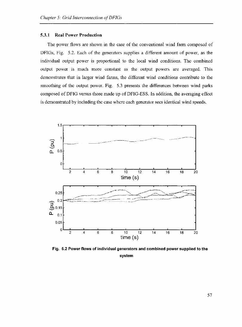
Chapter 5: Grid Interconnection of DFIGs
5.3.1 Real Power Production
The power flows are shown in the case of the conventional wind farm composed of
DFIGs, Fig. 5.2. Each of the generators supplies a different amount of power, as the
individual output power is proportion al to the local wind conditions. The combined
output power is much more constant as the output powers are averaged. This
demonstrates that in larger wind farms, the different wind conditions contribute to the
smoothing of the output power. Fig. 5.3 presents the differences between wind parks
composed of DFIG versus those made up of DFIG-ESS. In addition, the averaging effect
is demonstrated by induding the case where each generator sees identical wind speeds.
1.5r-,_----r_--~----~----~--~----_r----,_----r_--~
...--.. ::J 0.. --D.. 0.5
0
2 4 6 8 10 12 14 16 18 20
time (8)
0.25
...--.. 0.2 ::J
-.9:0.15
D.. 0.1
0.05
0 2 4 6 8 10 12 14 16 18 20
time (8)
Fig. 5.2 Power flows of individual generators and combined power supplied to the
system
57

Chapter 5: Grid Interconnection of DFIGs
-. :::J Cl. ---0...
1.4 Same Wind Speeds
1.2 /
0.8 ( 0.6 Different Wind Speeds Energy Storage Used
0.4
0.2
0
-0.2 2 4 6 8 10 12 14 16 18 20
time (8)
Fig. 5.3 Power supplied to the system for the cases of identical wind conditions,
different wind conditions, and DFIGs with energy storage
5.3.2 Voltage Regulation
Although the reactive power ratings of the two different wind generator topologies are
identical, the reactive power requirements depend close1y on the output power of the
generators. In the above cases, the reactive power reference is chosen to regulate the
voltage at the point of connection of the wind turbine to 1 pu, with a 3 % droop. Due to
the fluctuating output power in the case of the DFIG alone, the reactive power also
fluctuates in order to regulate the terminal voltage to the required reference. In the case of
the DFIG-ESS, the output power is held constant and with aIl other things being equal,
the reactive power supplied by the generator remains constant as well, Fig. 5.4. In
addition, the reactive power supplied is fairly small, since the real power is regulated
close to the rating of the machine, which allows a given margin for reactive power
capability under transient conditions.
58

Chapter 5: Grid Interconnection of DFIGs
0.5
0.4
0.3
0.2
0.1 ....-:::J DFIG with Energy Storage Cl. 0 --- / a
-0.1
-0.3
/ -0.4 DFIG
-0.5 2 4 6 8 10 12 14 16 18 20
time (s)
Fig. 5.4 Reactive power supplied by wind farm with and without energy storage
5.4 Power System Disturbances
The performance of the system in response to various disturbances was investigated
since the transient stability of the system depends on its ability to handle various
contingencies that can occur within the system. The various types of faults that can arise
are treated, inc1uding both permanent and temporary faults. The disturbances tested
follow in order of decreasing frequency and increasing severity. A summary of the faults
tested is inc1uded in Table 5.1 and the fault locations are presented in Fig. 5.5.
59
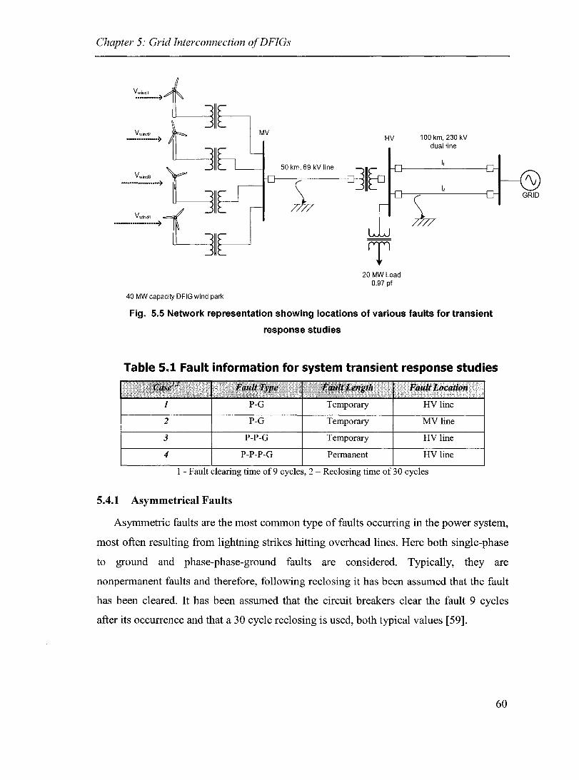
Chapter 5: Grid Interconnection of DFIGs
50 km, 69 kV line
40 MW capacity DFIG wind park
HV
20 MW Load 0.97 pf
100 km, 230 kV dualline
Fig. 5.5 Network representation showing locations of various faults for transient
response studies
Table 5.1 Fault information for system transient response studies
1 P-G Temporary HV line
2 P-G Temporary MV line
3 P-P-G Temporary HV line
4 P-P-P-G Permanent HV line
1 - F ault clearing time of 9 cycles, 2 - Reclosing time of 30 cycles
5.4.1 Asymmetrical Faults
Asymmetric faults are the most common type of faults occurring in the power system,
most often resulting from lightning strikes hitting overhead lines. Here both single-phase
to ground and phase-phase-ground faults are considered. Typically, they are
nonpermanent faults and therefore, following reclosing it has been assumed that the fault
has been cleared. It has been assumed that the circuit break ers clear the fault 9 cycles
after its occurrence and that a 30 cycle reclosing is used, both typical values [59].
60

Chapter 5: Grid Interconnection of DFIGs
5.4.1.1 Single-Phase to Ground
Single-phase to ground faults were considered on the HV transmission line as well as
on the MV distribution feeder. The case of the HV line is the least serious of all of the
faults considered since it is a dual transmission line, and the generators recover following
a short acceleration. Vpon rec1osing, there is a very small transient, so small it is hardly
noticeable, since the generators have already decelerated and the voltage has assumed its
normal operating value, Fig. 5.6. The conventional DFIGs performance resembles very
c10sely that of the DPlG with energy storage and no important differences can be noted.
1.5r----~.--~----~--~----~----~--_T----~--_,----~
--. :::J 0.. ---> 0.5
~.6 0.7
1.5
--. 11-- -:::J 0.. ---> 0.5
0 0.6 0.7
1
0.8 0.9
0.8 0.9
1.1
time(s)
1
1.1
time(s)
1.2
1.2
1.3 1.4 1.5 1.6
1.3 1.4 1.5 1.6
Fig. 5.6 Single phase fault on transmission line for DFIG (upper) and DFIG-ESS (Iower)
systems
The single phase fault on the MV line is a much more serious fault since it is located
much c10ser to the wind park itself and is the only connection between the park and the
rest of the system. As is sometimes done in protection systems, only the faulted phase is
opened, allowing continued connection of the two unfaulted phases and transmission of
power [59]. However, this implies unbalance operation of generators from the time of
61
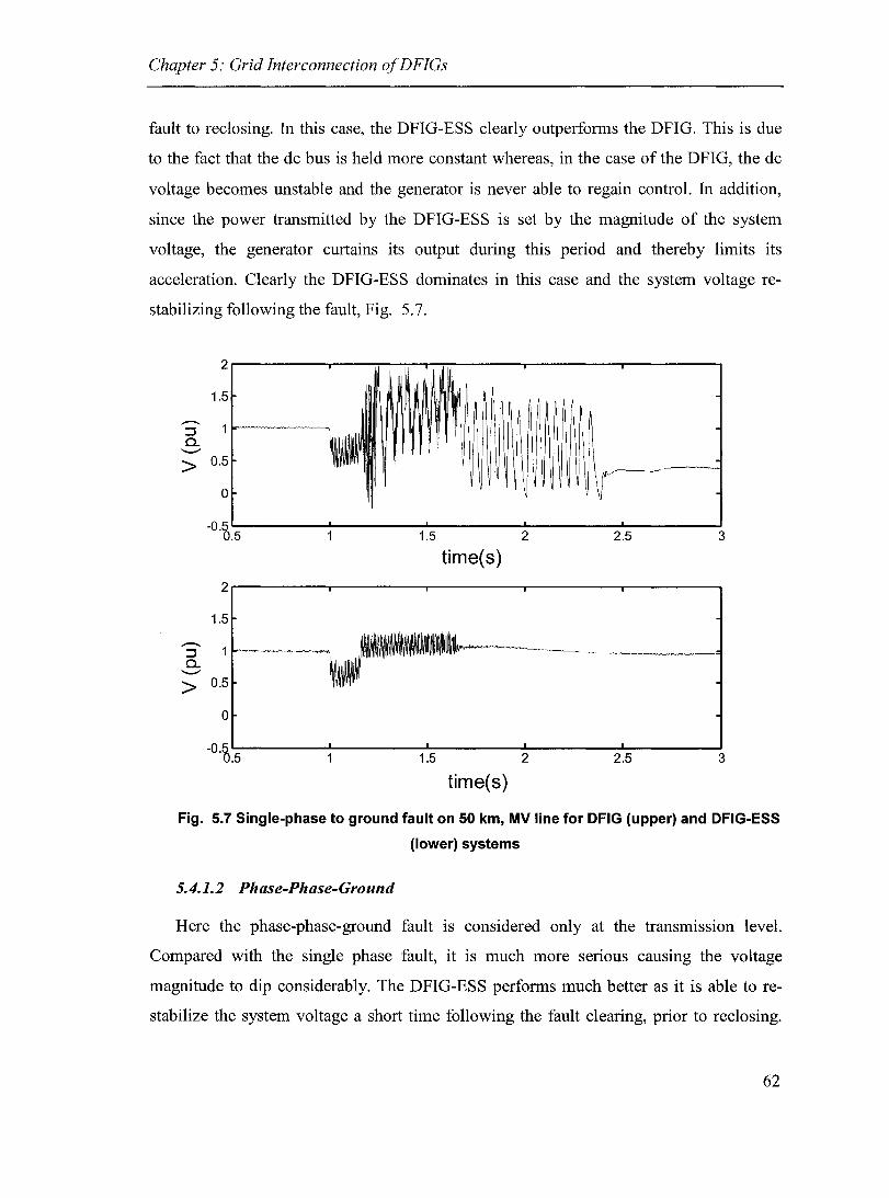
Chapter 5: Grid Interconnection of DFIGs
fault to reclosing. In this case, the DFIG-ESS clearly outperforms the DFIG. This is due
to the fact that the dc bus is held more constant whereas, in the case of the DFIG, the de
voltage becomes unstable and the generator is never able to regain control. In addition,
since the power transmitted by the DFIG-ESS is set by the magnitude of the system
voltage, the generator curtains its output during this period and thereby limits its
acceleration. Clearly the DFIG-ESS dominates in this case and the system voltage re
stabilizing following the fault, Fig. 5.7.
2
1.5
----::J a.
'"-""
> 0.5
0
-o.~ .5 1.5 2 2.5 3
time(s) 2
1.5
----::J a.
'"-""
> 0.5
0
-o.~ .5 1.5 2 2.5 3
time(s)
Fig. 5.7 Single-phase to ground fault on 50 km, MV line for DFIG (upper) and DFIG-ESS
(Iower) systems
5.4.1.2 Phase-Phase-Ground
Here the phase-phase-ground fault is considered only at the transmission level.
Compared with the single phase fault, it is much more serious causing the voltage
magnitude to dip considerably. The DFIG-ESS performs much better as it is able to re
stabilize the system voltage a short time following the fault clearing, prior to reclosing.
62
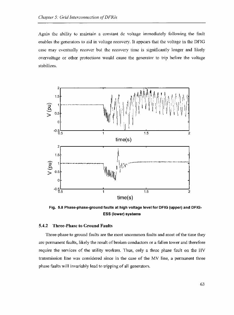
Chapter 5: Grid Interconnection of DFIGs
Again the ability to maintain a constant dc voltage immediately foIlowing the fault
enables the generators to aid in voltage recovery. It appears that the voltage in the DFIG
case may eventually recover but the recovery time is significantly longer and likely
overvoltage or other protections would cause the generator to trip before the voltage
stabilizes.
2
1.5
> 0.5
o
....--. ~ Co
---->
-0.5 0.5
2
1.5
0.5
0
-o.~ .5
~~~~~ ~ ~ ~:
,~ ~ ~
1.5 2
time(s)
1.5 2
time(s)
Fig. 5.8 Phase-phase-ground faults at high voltage level for DFIG (upper) and DFIG
ESS (Iower) systems
5.4.2 Three-Phase to Ground Faults
Three-phase to ground faults are the most uncommon faults and most of the time they
are permanent faults" likely the result ofbroken conductors or a fallen tower and therefore
require the services of the utility workers. Thus, only a three phase fault on the HV
transmission line was considered since in the case of the MV line, a permanent three
phase faults will invariably lead to tripping of aIl generators.
63

Chapter 5: Grid Interconnection of DFIGs
As in the previous two cases the DFIG-ESS system dominates and the system is
stablizes following the fault and the upon reclosing onto the fault. In the case of the
DFIG, voltage stability is lost and it never regains normal operation which would
eventually lead to tripping of the wind generators. Once again the loss of the dc voltage is
likely the root cause of the instability since the voltage stability is lost long before the
generator overspeed protection is activated.
2
1.5 -. ::l 0-
'-'"
> 0.5
0 -
-o.~ .5 1.5 2 2.5 3
time(s) 2
1.5 -. ::l 0-'-'"
> 0.5
0
-o.~ .5 1.5 2 2.5 3
time(s)
Fig. 5.9 Three phase permanent line to ground fault on dual transmission line
5.5 Conclusions
This chapter has highlighted the advantages of including energy storage in the design
of a DFIG based wind generator by considering the system level performance of a wind
park based on this technology. The performance of the wind generator is improved both
the areas of steady-state operating characteristics as weIl as the response to faults on the
system. The improvement of the transient performance appears to be due to the ability of
the DFIG-ESS to hold the dc bus voltage during faults and thereby continue to aid in
64

Chapter 5: Grid Interconnection of DFIGs
voltage support. The ability of the DFIG-ESS to curtail its output power during voltage
dips also helps to limit the acceleration of the machine and prevent the tripping of the
generator by the overspeed protection. However, the primary problem seems to be voltage
stability and not overspeed tripping. Also, the study reveals that asymmetrical faults
appear to be particularly problematic for the DFIG, perhaps as a result of unbalanced
operation.
This study is particularly interesting as is enables the study of a fairly large system
composed of DFIG generators and demonstrates the transient characteristics, offering
insight into the behaviour of unbalanced operation and the ability of the generator to
improve transient stability. It sets the framework for future studies to compare not only
the implementation of energy storage but perhaps more importantly the performance of
different wind generator topologies.
65
Chapter 6: Conclusions and Future Work
Chapter 6: Conclusions and Future Work
6.1 Summary
This work has contributed to the research on wind energy by exammmg the
advantages associated with the addition of an energy storage device to the DFlG design.
This was done first from the standpoint of a single machine and then was considered for
the case of a wind park. The research revealed benefits in terms of improved
controllability of output power and also improved response following local disturbances,
name1y symmetrical and asymmetrical faults. Although the work has given sorne insight
into what can be gained through the use of energy storage devices, there is still much to
be done in the areas of energy storage applications and wind energy.
6.2 Conclusions
Energy storage has long been considered for its use in conjunction with wind energy
conversion systems and in this work it has been studied using the DFlG topology. Just as
the DFlG is not always the chosen technology among wind turbine options, the type of
energy storage presented here wi11like1y not be suitable in aIl cases either. The technical
requirements associated with the integration of energy storage have been presented, from
the power electronics and control perspective.
Controllable output power is the main benefit to using an energy storage device.
Particularly in the case of a weak system, where the terminal voltage depends strongly on
the power flows, limiting the fluctuations in the output power can contribute to a more
stable voltage at the PCC and consequently to a reduction in fast reactive power
requirements. Furthermore, the ESS enables the maintenance of a firm dc bus voltage,
even during faults when short circuit CUITent contributions from the machine and the
inverter can cause steep drops or rises in the dc voltage.
66

Chapter 6: Conclusions and Future Work
Although mentioned briefly, the feasibility of this design was not examined in full,
something that would require extra attention in order for the DFIG-ESS hybrid to achieve
the same level of acceptance from the wind power industry that the conventional DFIG
has attained.
6.2.1 Doubly-Fed Induction Generator
The DFIG is one of the most popular choices for wind turbines due to the favorable
characteristics of variable speed operation, decoupled control of the real and reactive
power, speed control, and limited control over the output power. Therefore, the DFIG
became the logical choice for the study of integration of energy storage. In addition, it
requires a dc bus making the integration of energy storage easier since almost aIl ESS
require sorne kind of dc interconnection. A DFIG model was developed using both
EMTP-RV and MATLAB-SimPowerSystems and the control strategy was verified. The
allocation of reactive power was studied in detail and it was shown that the majority
should be delivered from the rotor si de converter in or to minimize CUITent flows and
consequently kVA ratings.
6.2.2 Energy Storage
Energy storage systems of large ratings are still relatively expensive, a characteristic
which slows their implementation in power system applications. There exist many
different technologies and here supercapacitors were applied in order to smooth the
fluctuations in the wind generator output power.
Following cross validation of the developed DFIG wind turbine model,
supercapacitors were added to the design, interfaced with the dc bus using a two-quadrant
dc/dc chopper. This design enabled the turbine to schedule the output power accurately,
while tracking the peak power points. In addition, the constant output power reduced the
fluctuations in reactive power requirements.
The benefits of energy storage were further demonstrated when comparing the system
level characteristics of the two generator designs. The DFIG-ESS showed more desirable
performance in terms of both steady-state operation and transient response. The energy
storage element enables the generator to maintain a more stable dc bus voltage even under
67

Chapter 6: Conclusions and Future Work
severe faults in the local power system. In addition, the DFIG-ESS can store sorne excess
power during local faults limiting the acceleration of the generator, and thereby
maintaining operation within the nonnallimits. Although voltage instability was observed
prior to over acceleration in the cases considered for the DFIG, overspeed tripping could
be greater factor for fault conditions not considered here or in the case of smaller
machines where the inertia of the machine is greatly reduced.
6.2.3 Alternate Topologies
Although the DFIG is one of the most promising technologies for wind power,
especially in the area of off-shore wind fanns, it will still have to compete with the other
fonns available, the direction in which industry seems to be headed. lnvestors may prefer
simpler technologies such as the squirrel cage induction machine or else the DFIG may
simply not be practical in sorne applications like distributed generation, where the size of
the turbine may be less than 1 MW. Furthennore the PMSM has been shown to be a
potential competitor in high power designs. However, in all these cases, energy storage
can still improve the system perfonnance, although the integration of the device may be
completely different from that presented.
The concept of distributed versus centralized energy storage can be illustrated by
comparing two different wind fanns: one composed of DFIG-ESS and another made up
of induction generators and a SMES. The two systems have similar characteristics from
the point of common coupling (PCC), however, they have very different structures,
controls, and protection. These concepts can be contrasted to learn more about not only
the operation of systems utilizing energy storage but also regarding the benefits of various
arrangements compared with their alternatives.
The application of energy storage and reactive power sources is becoming a subject
which is not only relevant to wind power but also to distributed generation and the
architecture of the future distribution networks. Before the implementation of energy
storage to even small wind power systems becomes a reality, reactive power and voltage
stability concerns will be increasingly investigated. The control of capacitor bank
switching and tap changing transfonners as well as the use of STATCOM and SVCs will
68

Chapter 6: Conclusions and Future Work
likely become very important issues in the near future whereas energy storage will follow
as a logical progression.
6.3 Future Work
The work presented here has only moderately investigated the application of energy
storage to wind power, with wind power being only one of a wide variety of possible
applications. Although the implementation of ESS to the DFIG has been outlined, the
same princip les and modeling are required for other energy storage devices but also for
other wind energy technologies. Following the development of the different systems, a
thorough comparison could be performed, looking at everything from performance
characteristics, to installation and operational costs, to the availability and practicality of
the various technologies.
6.3.1 Energy Management
The comparison of these different technologies invariably leads to issues regarding
control and management at a higher level. The problem of how to coordinate the flow of
energy as weIl as the dispatch of the various generators in a larger wind farm becomes a
complicated but interesting debate. Certainly there are optimal means of scheduling the
individual generators and the energy storage devices in order to achieve the desired
characteristics, while taking into account system losses, costs, and other limiting factors.
As weIl, due to the averaging effect in larger wind farrns the energy storage requirements
on a per machine basis are reduced. A systematic method for the rating of the storage
device from the single machine level to a large wind park needs to be developed. The
method used in the present work needs to be evaluated in terms of its relevance and the
resulting additional costs accrued.
As wind energy continues to grow worldwide, the effect of high penetration of wind
energy at the locallevel needs to be addressed further. Whether or not energy storage can
be used in order to limit the impact of high penetration of wind and also the spinning
reserve requirements needs to be determined. Moreover, the level at which wind energy
becomes important needs to be identified. How far this level can be extended by
69

Chapter 6: Conclusions and Future Work
incorporation of energy storage should be answered III order to have a method for
evaluation of its value and need.
6.3.2 Storage Deviee Energy Management
Additional work is required in the area of energy management for the storage device
itself, in particular how the energy flow is controlled. This is most evident when the
storage element reaches either the upper or lower limit. Likely the most favorable
characteristic will be obtained by curtailing the reference power once the storage device
approaches the lower limit. Likewise once the maximum storage capacity is neared the
output power reference should be increased. In this way, the time that the system remains
in normal operation can be extended using these slight variations on the general control
scheme. The transition between the states of operation will likely be smoothed as weIl
thereby contributing to an overall improvement in the performance of the system. These
studies could first be accompli shed for the single machine and then extended to the more
complicated case of a wind park where other methods may be required in order to
optimize aIl of the benefits of energy storage.
6.3.3 Distributed Generation and MieroGrids
The case of a single machine is most relevant for distributed generation and this
presents a wide range of possibilities in the area of energy storage applications. As the
penetration of distributed generators increases in the power system, the energy storage
requirements will undoubtedly increase in a similar fashion. Particularly in the area of
MicroGrids, where a section of the power system may be required to support itself while
temporarily disconnected from the grid, the need for energy storage devices is imperative
when the generation is based on intermittent power supply technologies, in order to avoid
any type of load shedding.
The growth of distributed or embedded generation will most likely be accompanied
by a growth in the energy storage industry or at least a renewed focus on the management
of energy. The interface ofthese technologies may not be limited DG alone, as the dc link
of variable speed drives or other self-commutated rectifiers may be utilized to integrate
either ESS or dc generation systems such as photovoltaics (PV). The move towards more
70

Chapter 6: Conclusions and Future Work
intelligent buildings and the use of vanous hybrid systems will also drive the
restructuring of the grid, at least at the distribution level. Maximization of the benefits of
ESS and other new technologies will require an increased focus on the way these devices
are operated and controlled, at both the micro and macro-levels.
71
References
[1] Swisher, R., C. Real de Azua, and J. Clendenin, "Strong winds on the horizon: wind power cornes of age," IEEE Proc., Vol. 89, No. 12, Dec. 2001.
[2] "Non dispatchable production in the Nordel System," Annual Meeting of Nordel's Grid Group, May 2000.
[3] Rodriguez, J.M., J.L. Femandez, D. Beato, R. Iturbe, J. Usaola, P. Ledesma, and J. R. Wilhelmi, "Incidence on power system dynamics of high penetration of fixed speed and doubly fed wind energy systems: study ofthe Spanish case," IEEE Trans. Power Sys., Vol. 17, No. 4, Nov. 2002.
[4] Lemogo Kana, C., M. Thamodharan, and A. Wolf, "System management ofa windenergy converter," IEEE Trans. Power Elec., Vol. 16, No. 3, May 2001.
[5] Grainger, B. and T. Thorogood, "Beyond the harbour wall" IEE review, March 2001.
[6] Chen. Z., and E. Spooner, "Grid power quality with variable speed wind turbines," IEEE Trans. Energy Conv., Vol. 16, No. 2, June 2001.
[7] Fairley, P. "Steady as she blows," IEEE Spectrum, August 2003.
[8] Kirby, N. M., L. Xu, M. Luckett, and W. Siepmann, "HVDC transmission for large offshore wind farms," IEE Power Engineering Journal, June 2002.
[9] Ackermann, T., "Transmission systems for offshore wind farms," IEEE Power Eng. Review, Dec. 2002.
[10] Voropai, N. 1., "Use ofnew energy technologies in the Asian part of Russia," IEEE PES Review, July 2001.
[11] Bakshi, R., "Wind energy in India," IEEE PES Review, Sept. 2002.
[12] Belhomme, R. "Wind power developments in France," IEEE PES Review, Oct. 2002.
[13] IEEE Standard for Distributed Resources Interconnected With Electric Power Systems, IEEE CC21, IEEE P1547 Std Draft 06, 2000.
[14] GE Corporate Research and Development. "Reliable, Low Cost Distributed GeneratorlUtility System Interconnect: 2001 Annual Report" NREL/SR-560-34634. Golden, Colorado: National Renewable Energy Laboratory. August 2003.
[15] Slootweg, J. G. "Wind power: Modelling and impact on power system dynamics," Ph. D Thesis, Department of Computer and Electrical Engineering, Technische Universiteit Delft, Dec. 2003.
72

[16] CIGRE TF38.01.10 "Modeling of new forms of generation and storage," Nov. 2000.
[17] Blaabjerg, F., G. J06s, and K. Rajashekara, "Distributed power generation technology, application and interconnection issues," IEEE lAS Tutorial, Salt Lake City, Oct. 2003.
[18] Kanellos, F.D., and N.D. Hatziargyriou, "The effect ofvariable-speed wind turbines on the operation of weak distribution networks," IEEE Trans. Energy Conv., Vol. 17, No. 4, Dec. 2002.
[19] Balasubraxpanian, R., M. Kalantar, and S.C. Tripathy, "Dynamics and stability of wind and diesel turbine generators with superconducting magnetic energy storage unit on an isolated power system" Energy Conversion, IEEE Transactions on , Volume: 6 Issue: 4 ,Dec 1991 Page(s): 579 -585
[20] Lu, Weixing and B.T. Ooi, "Multiterminal LVDC system for optimal acquisition of power in wind-farm using induction generators", IEEE Trans. Power Elec., Vol. 17, No. 4, July 2002.
[21] Rodriguez-Amenedo, J.L., S. Amalte, and J.C. Burgos, "Automatic generation control of a wind farm with variable speed wind turbines", IEEE Trans. Energy Conv., Vol. 17, No. 2, June 2002.
[22] Yang, Z., C. Shen, L. Zhang, M.L. Crow, and S. Atcitty, "Integration of a StatCom and battery energy storage", IEEE Trans. Power Sys., Vo1.l6, No. 2, May 2001
[23] Barker, P. "Ultracapacitors for use in power quality and distributed resource applications" IEEE-PES Summer Meeting, Vol 1., pp. 316-320, July 2002
[24] Bhargava, B. and G. Dishaw, "Application of an energy source power system stabilizer on the 10 MW battery energy storage system at Chino substation," IEEE Trans. Power Sys., Vol. 13, No. 1, Feb. 1998.
[25] Ribeiro, P. F., B. K. Johnson, M. L. Crow, A. Arsoy, and Y. Liu, "Energy storage systems for advanced power applications," IEEE Proc., Vol. 89, No. 12, Dec. 2001.
[26] Key, T., "Fast response, load matching hybrid fuel cell," EPRI-PEAC Quaterly Review Meeting, Washington D.C., July 2001.
[27] Boyes, J.D. and N. Clark, "Flywheel energy storage and super conducting magnetic energy storage systems," IEEE-PES Summer Meeting 2000, Seattle, July 2000.
[28] Arsoy, A. B., Z. Wang, Y. Liu, and P. F. Ribeiro, "Transient modeling and simulation of a SMES coi! and the power electronic interface," IEEE Trans. App!. Supercond., Vol. 9, No. 4, Dec. 1999.
73

[29] Holdsworth, L., X. G. Wu, J.B. Ekanayake, and N. Jenkins, "Comparison of fixed speed and doubly-fed induction wind turbines during power system disturbances," IEE Proc.-Gener. Transm. Distrib., Vol. 150, No. 3, May 2003.
[30] R. Pena, J.C. Clare and G.M. Asher, "Doubly fed induction generator using backto-back PWM converters and its application to variable-speed wind-energy generation" Proc.-Electr. Power Appl., Vol. 143, No. 3, May 1996
[31] Neris, A.S, N.A. Vovos, and G.B. Giannakopoulos, "A variable speed wind energy conversion scheme for connection to weak ac systems," IEEE Trans. Energy Conv., Vol. 14, No. 1, March 1999.
[32] Bansal, R.C., T.S. Bhatti, and D. P. Kothari, "Bibliography on the application of induction generators in nonconventional energy systems," IEEE Trans. Energy Conv., Vol. 18, No. 3, Sept. 2003.
[33] Abdin, E. S. and W. Xu, "Control design and dynamic performance analysis of a wind turbine-induction generator unit," IEEE Trans. Energy Conv., Vol. 15, No. 1, March 2000.
[34] Peresada, S., A. Tilli, and A. Tonielli,"Indirect stator flux-oriented output feedback control of a doubly fed induction machine," IEEE Trans. Control Sys., Vol. Il, No. 6, Nov. 2003.
[35] Datta, R. and V. T. Ranganathan, "Variable-speed wind power generation using doubly fed wound rotor induction machine - a comparison with alternative schemes," IEEE Trans. Energy Conv., Vol. 17, No. 3, Sept, 2002.
[36] Datta, R. and V.T. Ranganathan, "Direct power control of grid-connected wound rotor induction machine without rotor position sensors," IEEE Trans. Power Elec., Vol. 16, No. 3, May 2001.
[37] Ekanayake, J.B., L. Holdsworth, X.Wu and N. Jenkins, "Dynamic modeling of doubly fed induction wind turbines," IEEE Trans. Power Sys., Vol. 18, No. 2, May 2003.
[38] Datta, R. and V.T. Ranganathan, "A simple position-sensorless algorithm for rotorsi de field-oriented control of wound-rotor induction machine," IEEE Trans. Ind. Elec., Vol. 48, No. 4, August 2001.
[39] Morel, L., H. Godfroid, A. Mirzaian, and J.M. Kauffinann, "Double-fed induction machine: converter optimization and field-oriented control without position sensor", IEE Proc.-Electr. Power Appl., Vol. 145, No. 4, July 1998.
[40] Zhang, L., C. Watthanasarn, and W. Shepherd, "Application of a matrix converter for the power control of a variable-speed wind-turbine driving a doubly-fed induction generator," Conf. Indus. Elec., Cont., Instr., Vol. 2 , Nov. 1997.
74

[41] Muller, S., M. Deicke, and R. W. De Doncker, "Doubly fed induction generator systems for wind turbines," IEEE lAS Magazine, June 2002.
[42] Tapia, A., G. Tapia, J. Xabier Ostolaza, and J. R. Saenz, "Modeling and control of a wind turbine driven doubly fed induction generator," IEEE Trans. Energy Conv., Vol. 18, No. 2, June 2003.
[43] Datta, R. and V.T. Ranganathan, "A method oftracking the peak power points for a variable speed wind energy conversion system," IEEE Trans. Power Elec., Vol. 16, No. 3, May 2001.
[44] Akagi, H. and H. Sato, "Control and performance of a doubly-fed induction machine intended for a flywhee1 energy storage system," IEEE Trans. Power Elec., Vol.17,No.l,Jan2002.
[45] P.C. Krause, "Analysis of Electric Machinery", McGraw-Hill Book Company, 1986.
[46] Abbey, C., and G. J06s, "Optimum reactive power allocation in a doubly-fed induction machine for wind power applications," IEEE-PES General Meeting, June, 2004.
[47] Gyugyi, L.: "Dynamic compensation of AC transmission lines by solid-state synchronous voltage sources", IEEE Trans. Power Delivery, 1994, Vol 9, No. 2, pp. 904-911.
[48] Hirachi, K., K. Kajiyama, S. Isokane, and M. Nakaoka, "Couple inductor assisted bidirectional chopper for small-scale battery energy storage system," Electronic Letters, Vol. 39, No. 20, Oct. 2003.
[49] Dougal, R. A., S. Liu, and R. E. White, "Power and life extension of batteryultracapacitor hybrids," IEEE Trans. Comp. Pack. Tech., Vol. 25, No. 1, March 2002.
[50] Cardenas, R., R. Pena, G. Asher, and J. Clare, "Control strategies for enhanced power smoothing in wind energy systems using a flywhee1 driven by a vectorcontrolled induction machine," IEEE Trans. Indus. Elec., Vol. 48, No. 3, June 2001.
[51] Vajda, 1., Z. Kohari, L. Benko, V. Meerovich, and W. Gawalek, "Investigation of joint operation of a superconducting kinetic energy storage (flywhee1) and solar cells," IEEE Trans. Applies Supercond., Vol. 13, No. 2, June 2003.
[52] Cardenas, R., R. Pena, G. Asher, and J. Clare, "Power smoothing in wind generation systems using a sensorless vector controlled induction machine driving a flywheel," IEEE Trans. Energy Conv., Vol. 19, No. 1, March 2004.
[53] Balasubramanian, R., M. Kalantar, and S.C. Tripathy, "Dynamics and stability of wind and diesel turbine generators with superconducting magnetic energy storage
75

unit on an isolated power system", IEEE Trans. Energy Conv. , Vol. 6, No. 4 , Dec 1991.
[54] Abbey, C. and G. J06s, "Integration of energy storage with a doubly-fed induction machine for wind power applications", PESC 2004, Aachen, Germany, June 2004.
[55] Zhou, F., G. J06s, C. Abbey, L. Jiao, and B.T. Ooi, "Use oflarge capacity SMES to improve the power quality and stability of wind farms," IEEE-PES General Meeting, June, 2004
[56] Palsson, M.P.; Tande, J.O.G.; Toftevaag, T.; Uhlen, K.; "Large-scale wind power integration and voltage stability limits in regional networks" Power Engineering Society Summer Meeting 2002, Vol 2., pp. 762 -769
[57] Kolluri, S. "Application of distributed superconducting magnetic energy storage system (D-SMES) in the entergy system to improve voltage stability" IEEE Power Engineering Society Winter Meeting, Vol. 2, 2002.
[58] Ross, M., M. Borodulin, and Y. Kazachkov, "Using D-SMES devices to improve the voltage stability of a transmission system" IEEEIP ES Transmission and Distribution Conference and Exposition, Vol. 2, 200l.
[59] Network Protection & Automation Guide, ALSTOM, T & D Energy Automation & Information, 2002, Levallois-Perret, France.
[60] website: www.winddata.com.
[61] Abbey, C. and F. Zhou, "Wind power modeling using EMTP-RV", EMTP-RV course notes, TransÉnergie Technolgies, June 2004.
[62] Abbey, C., Bahram Khodabahkchian, and G. Joos, "EMTP-RV modeling of a threelevel voltage source converter based STATCOM", EMTP-RV course notes, TransÉenergie Technologies, June 2004.
[63] Zhou, F., G. Joos, C. Abbey, and L. Jiao, "Optimal State Control for CSI Superconducting Magnetic Energy Storage System", PowerCon 2004, Singapore, Nov. 2004.
[64] Jiao, L., G. J06s, C. Abbey, F. Zhou, and B.T. Ooi, "A multi-terminal dc network doubly-fed induction generator for wind power applications," PESC 2004, Aachen, Germany, June 2004.
76

Appendix A: Wind Models
This section presents the various models required for representation of a wind turbine. For
more detailed treatment of this topic, readers are referred to [15] - [17].
A.1 Wind Speed
The wind speed is typically composed of four different components and can be
represented using a mathematical representation or by using typical wind speed
measurements as taken from [60]. Fig. Al.l shows a typical plot of data obtained from
the website.
14,-------------------------------~
A.2 Torque Model
The wind speed is translated into input torque using the basic wind function which
depends on local environrnental conditions (air density and wind speed), the size of the
blades, the speed of the machine, as weIl as a characteristic torque coefficient which
depends on the nature of the machine and is related to aerodynarnics, machine rating and
mechanical factors.
(A.l)
where
p : The air density
R : The wind turbine radius
77

 = OJmR : The ratio ofblade tip speed to wind speed. Vw
OJm : The wind turbine rotational speed (rad /sec.)
p : Blade pitch angle
The wind turbine blade aerodynamics is characterized by non-dimensional curve of
torque coefficient, Cp, which is a function oftip-speed ratio, À, and blade pitch angles, p.
(A.2)
(A.3)
Literature [19] gives the parameters ofMOD 2 turbine, where
and 1 1 0.035 =-------
~ Â + 0.080 0 3 + 1
The torque coefficient for various blade angles is plotted below for the range of tip-speed
ratios.
78
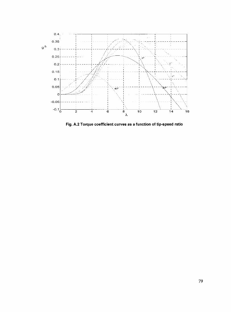
o.4,-------,-------c--------,-------,-------,------~--------,_----__,
- ;;-" =--c.<.,:::>."'-. _ ~ _ :....:.~ ______ ...J ______ 1 _____ _
l " 1
1 \ 1 - - r - - - - \,- T - - - 2.. - - -1 - - ~, - - - -1- - - - - -
____ ~ ______ : _ 0 ___ --1
1\ 0° l" 1
0.35 1
______ L ______ ~ _______ L_
1
0.3 1
1 1 ------T------,------
------+------~----0.25
-:-------~------: \----~-1 1 1 \ 1
0.2
1 1 1 1
0.15 - - - -:- - - -- - -~- - - - - - ~ - - \ - - ~- - - - - - -1- - ~ - --
1 1 1 \ 1 1 10
o
- - - - -:- - - - - - -~ - - - - -- + - -- -\ - -1- - - - - - - - - - -,
~ 1 1 \\ 1 " 1 1 1 1 1 \
~ - - - - - - -:- -,400 - - ~ - - - - - - i - - - - - ~ - - - 00- -:-
1 1 1 1 \1 1 _____ J _______ 1 ____ ". ___ L ______ 1 _____ __ \ ___ ____ 1 __ _
1 l ' 1 1 1\ 1
0.1
0.05
-0.05 - - - - - - T - - - - - - ~ - - - - - - _: __ - __ - 1 ______ ~ ______ ~\ _____ : ____ _
1 1 1 1
-0.10L-----~2-------4L-----~6~----~8-L----~1~0------1~2~L---~--~~16
À
Fig. A.2 Torque coefficient curves as a function of tip-speed ratio
79

A.3 Wind Power Characteristic
Upon plotting of the torque speed curve, a similar curve can be obtained which describes
the output power of a wind turbine which is a function of the input torque and the
operating rotor speed. Typically, the wind generator speed range is limited to near
synchronous speed (± 20 %) as given in Fig. A1.3, which illustrates the power
characteristic for a 2 MW machine.
0.6 0.7
1 , 1.------,
0.8
Range of Operation
+1-20% slip
0.9 1.1
Rotor speed (pu) 1.2 1.3
Fig. A.3 Wind power characteristic curves (red) and optimum power points (blue)
80

Appendix B: Modet Parameters
Wound rotor induction machine parameters
Rated Voltage (kV) 4
Rated Power (MVA) 7.46
R1 (pu) 0.00621
R2' (pu) 0.00627
X1 (pu) 0.117
X2' (pu) 0.1136
Xm (pu) 3.28
Us (turns ratio) 1.547
pole pairs 3
Machine Type Wound-rotor
Inertia Constant, H 1
(s)
Voltage trip Set to permit low
voltage ride-through
Network data
0 1 0 1 2
0.53 0.053 0.5306 0.0117 0.0304
1.59 0.53 1.521 0.327 0.656
5.21 5.21 3.239 4.92 3.239
single - three phase dual - three phase
50 100
81

Appendix C: Wind Park SCC
The network can for most purposes be represented by its Thevenin equivalent at the point
of connection. The type of connection can then be mode1ed by simply adjusting the short
circuit ratio (SCR), given by:
SCR= SCC Shase
(C.I)
Where SCC is the short circuit capacity of the grid defined by
2
SCC=~ Ze
(C.2)
Where Ve is the RMS of line-to-line voltage and Ze is the Thevenin impedance, which
represents the combined impedances of transmission lines, transformer leakage
reactances, and internaI generator impedances. The SCR can be adjusted by increasing or
decreasing the Thevenin impedance.
In the case of a wind farm, Sbase is defined by the total instaHed capacity of the wind farm.
Lengthening the transmission lines or changing the line parameters (re1ated to the types of
conductors), or voltage levels can aH contribute to a weak system.
82

Appendix D: Droop Characteristic
The steady-state operation of the DFIG can be represented by a PQ bus with a variable P
which is dependent on the wind variation and whose reactive injections are a function of
the reference voltage at the pcc. The reference voltage depends on the percentage of
rated reactive power supplied, known as the droop characteristic, whereby the reference
voltage is slightly less at maximum leading reactive CUITent and slightly greater at
maximum lagging reactive CUITent. Typically, the variation in the reference voltage is 3%
and this characteristic results in the following benefits [47]:
(i) The linear operating region ofthe compensator can be extended (ii) Strictly defined voltage reference can result in a poody defined operating
point and resulting oscillations. (iii) The slope can lead to favorable compensation sharing by numerous
regulation devices which are connected at various points in the system.
DFIG
'comp max
Capacitive Inductive
Fig. 0.1 Oroop characteristic for determination of OFIG reference voltage
The reactive power for the DFIG is divided between the supply side and rotor side
converters in the 20 / 80 % manner, as explained in detail in [46].
83
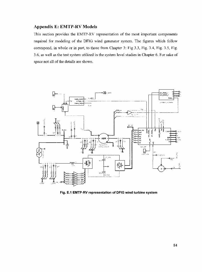
Appendix E: EMTP-RV Models
This section provides the EMTP-RV representation of the most important components
required for modeling of the DFlG wind generator system. The figures which follow
correspond, in whole or in part, to those from Chapter 3: Fig 3.3, Fig. 3.4, Fig. 3.5, Fig.
3.6, as well as the test system utilized in the system level studies in Chapter 6. For sake of
space not all of the details are shown.
Tm
-----l
LI· ~L"o °1" 'I~ J , Jtl .-----,. .; - ~
pi> ~<0-,
T
Wo,.o'"-,oo_o" -~ w-',o °
,,<1,") ,{} pl
f t 1 ~ , f f t, ': : ~ " ',S ~
sw m Vf:onv LCO!W"·
v wind
sin_theta_r '+--lcos_theta_r i
theta_r
Fig. E.1 EMTP-RV representation of DFIG wind turbine system
84

beta va cos
~JC" Pref vb theta Qref vc sin
1&1;:: Ps Iq
C i ''--it,~
theta
i_conv v conv sw rec
icon\.q
i; Qcont 0
' -,; -,;
&-------------------4 l, C83--,----,
" Slip sall---,)() ,---=-----Icos_theta_r sbll--,><>
,~____ _ _________ -' r-------I;~:~heta-' sclr---I:~ ,~--------
Fig. E.2 EMTP-RV representation of overall control structure
v~----..... ~ ~:"~.
,; ib
,AID--------------;:=+==~QS-'ef ir
:::,Iipjg) Slip
','l,,~-----_'
cos _ theta_r sin_theta_r theta
sta!u.lrJ rdor
Fig. E.3 EMTP-RV representation of PQ control
85

:kü
o q Q cos_theta r sin_ theta _f
v ~ 1 r=1-, + ~, -" out + + -<
Fig. E.4 EMTP-RV representation of PI control for rotor side converter
J":~': ----a
. =.=';;~'"'-'::---. b v:\ ,:l\llV
f!lte, 55 te) DG
v ':OIlV
vdclx:>------,
vdc __ ld
vdc __ mf~
QcontlX>-------il{
va cos sin
vb theta vc Ireq
PLL
PI
'---~C="--tia '-__ -'1\"-' -"","')'-""'C-lib
le con\' ie
""'-"'=----1 va ""'-==----Ivb ""'''-'''=----Ivc
P Q
III )h h .:.1 cc
ia_ref ia
I--c----iib rel ib-ie_ret ic h
il CO!)V a lb UJrlV b fi_ l;VI\V C
thela <:onv theta Z
sau sai
sbu sbl scu sel
Fig. E.5 EMTP-RV representation of supply-side converter control
---IDI<.'>11V'1
86

Fig. E.6 EMTP-RV representation higher level controls
4x (10X1 MW) doubly-fed induction machines
"'1
L J4=_··_._,---..1_0_0_km_23_0_k_V_lin_e-,-H~V ~~ .. ' f 20 MWLoad
Fig. E.7 EMTP-RV representation of weak power system used
87