Embed Size (px)
Citation preview
I N D O O R A I R Q U A L I T Y
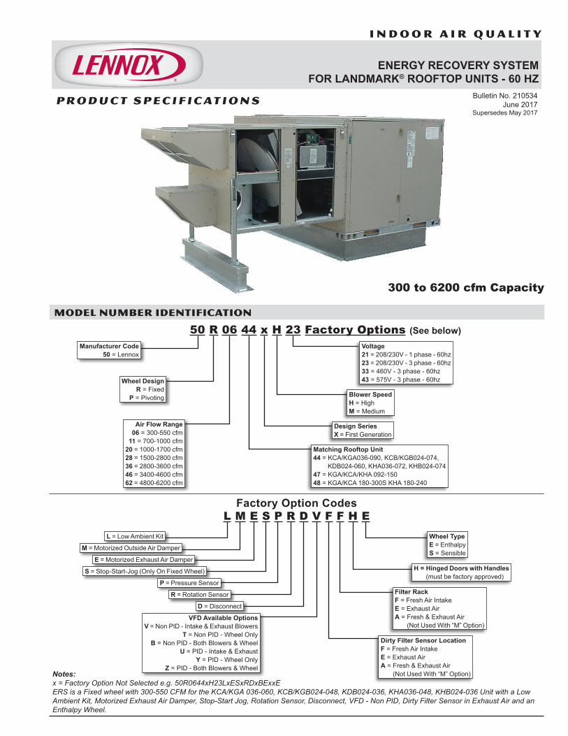
ENERGY RECOVERY SYSTEMFOR LANDMARK® ROOFTOP UNITS - 60 HZ
MODEL NUMBER IDENTIFICATION
Bulletin No. 210534 June 2017
Supersedes May 2017
300 to 6200 cfm Capacity
Notes:x = Factory Option Not Selected e.g. 50R0644xH23LxESxRDxBExxEERS is a Fixed wheel with 300-550 CFM for the KCA/KGA 036-060, KCB/KGB024-048, KDB024-036, KHA036-048, KHB024-036 Unit with a Low Ambient Kit, Motorized Exhaust Air Damper, Stop-Start Jog, Rotation Sensor, Disconnect, VFD - Non PID, Dirty Filter Sensor in Exhaust Air and an Enthalpy Wheel.
Manufacturer Code 50 = Lennox
Voltage 21 = 208/230V - 1 phase - 60hz 23 = 208/230V - 3 phase - 60hz 33 = 460V - 3 phase - 60hz 43 = 575V - 3 phase - 60hz
50 R 06 44 x H 23 Factory Options
L M E S P R D V F F H EFactory Option Codes
L = Low Ambient Kit
M = Motorized Outside Air Damper
E = Motorized Exhaust Air Damper
S = Stop-Start-Jog (Only On Fixed Wheel)
P = Pressure Sensor
R = Rotation Sensor
D = Disconnect
VFD Available Options V = Non PID - Intake & Exhaust Blowers
T = Non PID - Wheel Only B = Non PID - Both Blowers & Wheel
U = PID - Intake & Exhaust Y = PID - Wheel Only
Z = PID - Both Blowers & Wheel
Wheel Type E = Enthalpy S = Sensible
H = Hinged Doors with Handles (must be factory approved)
Filter Rack F = Fresh Air Intake E = Exhaust Air A = Fresh & Exhaust Air
(Not Used With “M” Option)
Dirty Filter Sensor Location F = Fresh Air Intake E = Exhaust Air A = Fresh & Exhaust Air
(Not Used With “M” Option)
(See below)
P R O D U C T S P E C I F I C AT I O N S
ENERGY RECOVERY SYSTEM FOR LANDMARK® ROOFTOP UNITS
Wheel Design R = Fixed
P = Pivoting
Matching Rooftop Unit 44 = KCA/KGA036-090, KCB/KGB024-074, KDB024-060, KHA036-072, KHB024-074 47 = KGA/KCA/KHA 092-150 48 = KGA/KCA 180-300S KHA 180-240
Design Series X = First Generation
Blower Speed H = High M = Medium
Air Flow Range 06 = 300-550 cfm
11 = 700-1000 cfm 20 = 1000-1700 cfm 28 = 1500-2800 cfm 36 = 2800-3600 cfm 46 = 3400-4600 cfm 62 = 4800-6200 cfm
Energy Recovery System (Landmark) / Page 2
FEATURES
APPROVALSRated in accordance with AHRI standard 1060-2005. To obtain a copy of the Standard or to view Lennox’ latest certified data, please visit the AHRI web site at http://www.ahrinet.org/. ETL Certified per UL 1995 and CSA/CAN C22.2 No. 236.
WARRANTY
Recovery Wheel - limited warranty for five years.All other covered components - one year limited warranty.
APPLICATIONS
The Lennox Energy Recovery System (ERS) is a constant volume, energy recovery ventilator that is directly coupled with Lennox Landmark™ rooftop units. Its primary function is to increase overall HVAC system efficiency and to reduce long-term energy costs. This is accomplished by capturing both sensible and latent energy from either the exhaust or intake air stream and transferring it to the other, resulting in reduced cooling loads at design temperatures up to four tons per 1000 cfm of outside air and reduced heating loads up to 12,000 Btuh per 400 cfm of outside air. The recovery wheel provides sensible and latent energy exchange between the entering and exhaust air streams of a building allowing a substantial amount of the energy, which is normally lost in the exhaust air stream, to be returned into the entering air. Each unit factory test operated to ensure proper operation.
OPERATION
The enthalpy wheel contains parallel layers of a polymeric material that is physically imbedded with a silica gel (desiccant).The wheel is located in the intake and exhaust air streams of the ventilation equipment.As the wheel rotates through each air stream, the wheel surface captures sensible and latent energy.In the heating mode, the wheel rotates to provide a constant transfer of heat from the exhaust air stream to the colder intake air stream. During the cooling season, the process is reversed.When used in conjunction with a rooftop unit equipped with an economizer, on pivoting models, the wheel pivots out of the air stream to allow the economizer to operate normally for “free cooling” when outdoor temperature and humidity is acceptable.By pivoting the wheel out of the air stream, the system can utilize 100% of the rooftop unit’s blower capabilities.During economizer operation, the exhaust blower continues to run, providing power exhaust for the system. The intake blower is de-energized during economizer operation.
ERS SELECTION
Step One - Determine the air conditioning load requirements using the required amount of outside air without an ERS.Step Two - Select the proper ERS for the outside air requirements and calculate the tonnage reduction.Select the rooftop unit required by reducing the load determined in step one by the reduction in step two. (Example: If the load in Step 1 was 10 tons, and the reduction in Step 2 was 2.5 tons, select a 7.5 ton unit).Select the proper ERS based on the selected unit.NOTE - The height of the roof top unit curb MUST correspond with the required curb height needed for the ERS. See Specifications Table.
SYSTEM FEATURES
Low-voltage logic board used to control frost protection and motorized outside air damper.Low-voltage terminal strip.Barometric relief dampers provided standard on all ERS units.Balancing dampers provided standard on all fixed wheel ERS units.Metal-mesh, mist-eliminator-type filters provided in intake air hood.Separate, fused power supply.Continuous operation down to 10°F without defrost at indoor relative humidity up to 40%. For temperatures below 10°F an optional, factory installed Low Ambient Control Kit is required.
CONTENTSDimensions ................................................................ 10Electrical Data ............................................................. 9Features....................................................................... 2Guide Specifications .................................................. 13Model Number Identification ........................................ 1Optional Accessories ................................................... 4Unit Clearances ......................................................... 11
Energy Recovery System (Landmark) / Page 3
RECOVERY WHEEL
AirXchange Enthalpy Wheels. Capable of both sensible and latent heat recovery. Dry energy transfer. Moisture in supply air stream is transferred to exhaust air stream in vapor state, eliminating condensate plumbing in the ventilator.Constructed of lightweight polymer material and coated with a desiccant silica gel that will not dissolve or liquefy in the presence of water or high humidity.Wheels 25 in. and larger in diameter are segmented for easy removal. Wheels less than 25 in. in diameter are removed from cabinet in a slide-out cassette.Patented, pivoting-wheel option allows unit to operate in true economizer mode when the outside temperature is suitable for cooling. Pivoting the wheel out of the air stream during economizer mode allows efficiencies to be maximized by reducing demand on the supply fan motor.
BLOWERS
Centrifugal, forward curved blowers provided for high-static capability and low sound levels.Belt-drive blowers have permanently lubricated ball bearings, overload protection, and adjustable sheaves for blower speed adjustment.
CABINET
Fully insulated with non-hygroscopic fiberglass insulation. Constructed of galvanized steel and finished with electrostatically bonded powdered enamel coating to withstand 1000 hour salt-spray test per ASTM B117.Attaches directly to the rooftop unit. All mounting hardware is provided.Adjustable support legs are provided.
OPTIONS / ACCESSORIES
FACTORY INSTALLED
Low Ambient Control KitPrevents frost formation on energy wheel heat transfer surfaces by terminating the intake blower operation when discharge air temperature falls below a field-selectable temperature setting.Intake blower operation resumes after temperature rises above the adjustable temperature differential. Kit includes temperature sensor.Motorized Outside Air DamperDamper mounts behind the outside air intake hood. Damper opens when the ERS is energized and closes when de-energized.Motorized Exhaust Air DamperDamper mounts in the barometric relief hood. Damper opens when the ERS is energized and closes when de-energized.
FEATURES
Stop-Start-Jog (Fixed Models Only)Control option that allows intermittent operation of the enthalpy wheel during mild outdoor conditions to provide cycling and cleaning of the wheel.Pressure SensorMeasures the amount of outside airflow across the enthalpy wheel.Rotation SensorVerifies the rotation of the enthalpy wheel.DisconnectOptional field device used to provide easy ability to switching the power on and off to the ERS. Must be field wired.VFD Blower ControlVariable frequency drives are available to control the speed of the blowers only. These VFD’s can be integrated with a building automation system to deliver precisely the amount of air needed to maximize efficiencies.Dirty Filter SensorThe dirty filter sensor sends a signal to field wired alarm when filters need to be cleaned or changed.Filter RackFilter racks filter air in both the intake and exhaust sections of ERS.Hinged Door with HandlesHinged panel access doors with quarter turn latches that allow for easy access to the energy recovery wheel, filters and blowers.Energy Recovery Wheel - Sensible TypeSensible Wheel type is used for sensible heat recovery.
FIELD INSTALLED
ERS Support8 inch high base for support of the exhaust and intake end of the ERS.Available in 48, 60, 76 inch lengths.See Page 4 for model numbers.ERS Roof CurbUsed to support RTU and raise them to the correct height for mounting.See Page 4 for model numbers.GFI Service OutletOptional field powered service outlet provides power for service equipment. Must be field installed and wired.See Page 4 for model numbers.NOTE - Contact your local Lennox Commercial Sales Representative for ordering information.
Energy Recovery System (Landmark) / Page 4
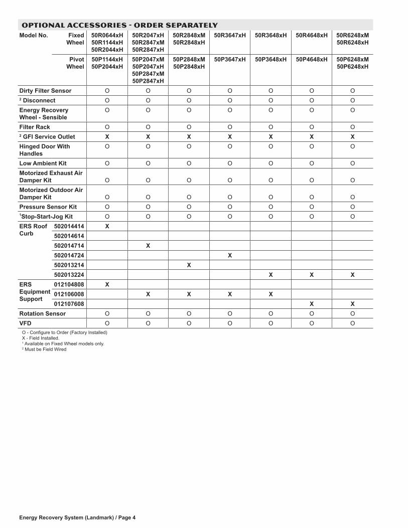
OPTIONAL ACCESSORIES - ORDER SEPARATELYModel No. Fixed
Wheel50R0644xH 50R1144xH 50R2044xH
50R2047xH 50R2847xM 50R2847xH
50R2848xM 50R2848xH
50R3647xH 50R3648xH 50R4648xH 50R6248xM 50R6248xH
Pivot Wheel
50P1144xH 50P2044xH
50P2047xM 50P2047xH 50P2847xM 50P2847xH
50P2848xM 50P2848xH
50P3647xH 50P3648xH 50P4648xH 50P6248xM 50P6248xH
Dirty Filter Sensor O O O O O O O2 Disconnect O O O O O O OEnergy Recovery Wheel - Sensible
O O O O O O O
Filter Rack O O O O O O O2 GFI Service Outlet X X X X X X XHinged Door With Handles
O O O O O O O
Low Ambient Kit O O O O O O OMotorized Exhaust Air Damper Kit O O O O O O OMotorized Outdoor Air Damper Kit O O O O O O OPressure Sensor Kit O O O O O O O1Stop-Start-Jog Kit O O O O O O OERS Roof Curb
502014414 X502014614502014714 X502014724 X502013214 X502013224 X X X
ERS Equipment Support
012104808 X012106008 X X X X012107608 X X
Rotation Sensor O O O O O O OVFD O O O O O O O
O - Configure to Order (Factory Installed)X - Field Installed. 1 Available on Fixed Wheel models only.2 Must be Field Wired
Energy Recovery System (Landmark) / Page 5
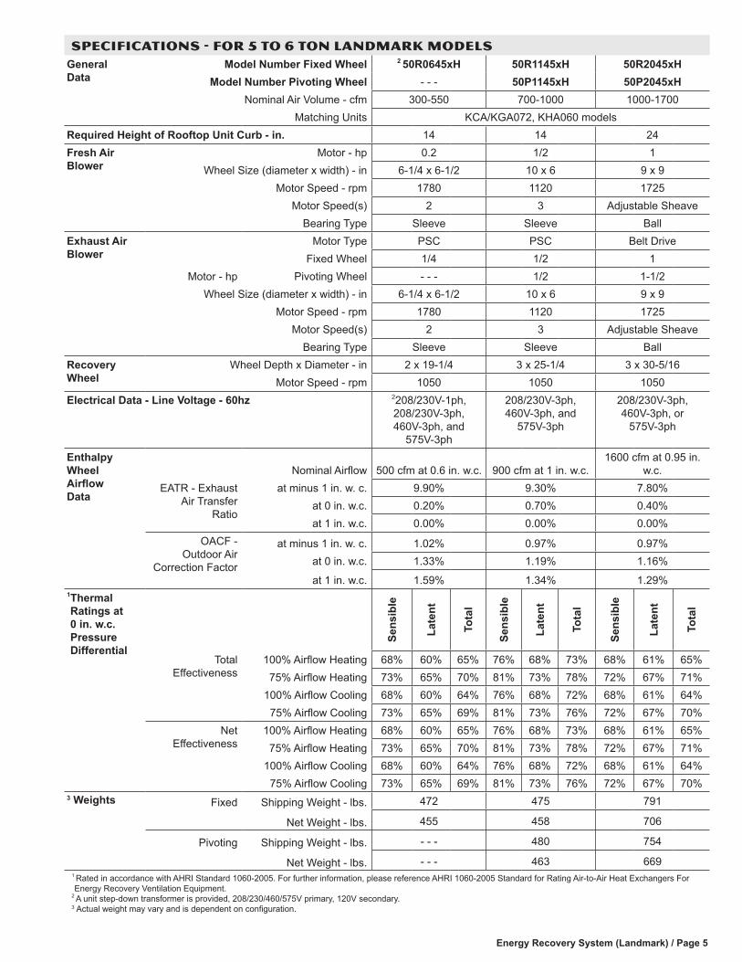
SPECIFICATIONS - FOR 5 TO 6 TON LANDMARK MODELSGeneral Data
Model Number Fixed Wheel 2 50R0645xH 50R1145xH 50R2045xHModel Number Pivoting Wheel - - - 50P1145xH 50P2045xH
Nominal Air Volume - cfm 300-550 700-1000 1000-1700Matching Units KCA/KGA072, KHA060 models
Required Height of Rooftop Unit Curb - in. 14 14 24Fresh Air Blower
Motor - hp 0.2 1/2 1Wheel Size (diameter x width) - in 6-1/4 x 6-1/2 10 x 6 9 x 9
Motor Speed - rpm 1780 1120 1725Motor Speed(s) 2 3 Adjustable Sheave
Bearing Type Sleeve Sleeve BallExhaust Air Blower
Motor Type PSC PSC Belt Drive
Motor - hpFixed Wheel 1/4 1/2 1
Pivoting Wheel - - - 1/2 1-1/2Wheel Size (diameter x width) - in 6-1/4 x 6-1/2 10 x 6 9 x 9
Motor Speed - rpm 1780 1120 1725Motor Speed(s) 2 3 Adjustable Sheave
Bearing Type Sleeve Sleeve BallRecovery Wheel
Wheel Depth x Diameter - in 2 x 19-1/4 3 x 25-1/4 3 x 30-5/16Motor Speed - rpm 1050 1050 1050
Electrical Data - Line Voltage - 60hz 2208/230V-1ph, 208/230V-3ph, 460V-3ph, and
575V-3ph
208/230V-3ph, 460V-3ph, and
575V-3ph
208/230V-3ph, 460V-3ph, or
575V-3ph
Enthalpy Wheel Airflow Data
Nominal Airflow 500 cfm at 0.6 in. w.c. 900 cfm at 1 in. w.c.1600 cfm at 0.95 in.
w.c.EATR - Exhaust
Air Transfer Ratio
at minus 1 in. w. c. 9.90% 9.30% 7.80%at 0 in. w.c. 0.20% 0.70% 0.40%at 1 in. w.c. 0.00% 0.00% 0.00%
OACF - Outdoor Air
Correction Factor
at minus 1 in. w. c. 1.02% 0.97% 0.97%at 0 in. w.c. 1.33% 1.19% 1.16%
at 1 in. w.c. 1.59% 1.34% 1.29%1 Thermal Ratings at 0 in. w.c. Pressure Differential
Sens
ible
Late
nt
Tota
l
Sens
ible
Late
nt
Tota
l
Sens
ible
Late
nt
Tota
l
Total Effectiveness
100% Airflow Heating 68% 60% 65% 76% 68% 73% 68% 61% 65%75% Airflow Heating 73% 65% 70% 81% 73% 78% 72% 67% 71%
100% Airflow Cooling 68% 60% 64% 76% 68% 72% 68% 61% 64%75% Airflow Cooling 73% 65% 69% 81% 73% 76% 72% 67% 70%
Net Effectiveness
100% Airflow Heating 68% 60% 65% 76% 68% 73% 68% 61% 65%75% Airflow Heating 73% 65% 70% 81% 73% 78% 72% 67% 71%
100% Airflow Cooling 68% 60% 64% 76% 68% 72% 68% 61% 64%75% Airflow Cooling 73% 65% 69% 81% 73% 76% 72% 67% 70%
3 Weights Fixed Shipping Weight - lbs. 472 475 791
Net Weight - lbs. 455 458 706
Pivoting Shipping Weight - lbs. - - - 480 754
Net Weight - lbs. - - - 463 6691 Rated in accordance with AHRI Standard 1060-2005. For further information, please reference AHRI 1060-2005 Standard for Rating Air-to-Air Heat Exchangers For Energy Recovery Ventilation Equipment.
2 A unit step-down transformer is provided, 208/230/460/575V primary, 120V secondary.3 Actual weight may vary and is dependent on configuration.
Energy Recovery System (Landmark) / Page 6
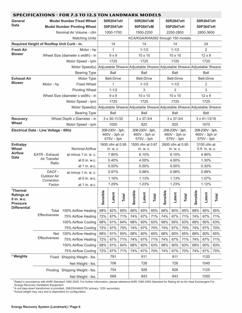
SPECIFICATIONS - FOR 7.5 TO 12.5 TON LANDMARK MODELSGeneral Data
Model Number Fixed Wheel 50R2047xH 50R2847xM 50R2847xH 50R3647xHModel Number Pivoting Wheel 50P2047xH 50P2847xM 50P2847xH 50P3647xH
Nominal Air Volume - cfm 1000-1700 1500-2200 2200-2800 2800-3600Matching Units KCA/KGA/KHA092 through 150 models
Required Height of Rooftop Unit Curb - in. 14 14 14 24Fresh Air Blower
Motor - hp 1 1-1/2 1-1/2 2Wheel Size (diameter x width) - in 9 x 9 10 x 10 10 x 10 12 x 9
Motor Speed - rpm 1725 1725 1725 1725Motor Speed(s) Adjustable Sheave Adjustable Sheave Adjustable Sheave Adjustable Sheave
Bearing Type Ball Ball Ball BallExhaust Air Blower
Motor Type Belt-Drive Belt-Drive Belt-Drive Belt-DriveMotor - hp Fixed Wheel 1 1-1/2 1-1/2 2
Pivoting Wheel 1-1/2 3 3 3Wheel Size (diameter x width) - in 9 x 9 10 x 10 10 x 10 12 x 9
Motor Speed - rpm 1725 1725 1725 1725Motor Speed(s) Adjustable Sheave Adjustable Sheave Adjustable Sheave Adjustable Sheave
Bearing Type Ball Ball Ball BallRecovery Wheel
Wheel Depth x Diameter - in 3 x 30-11/32 3 x 37-3/4 3 x 37-3/4 3 x 41-13/16Motor Speed - rpm 1050 825 825 1075
Electrical Data - Line Voltage - 60hz 208-230V - 3ph, 460V - 3ph or
575V - 3ph
208-230V - 3ph, 460V - 3ph or
575V - 3ph
208-230V - 3ph, 460V - 3ph or
575V - 3ph
208-230V - 3ph, 460V - 3ph or
575V - 3phEnthalpy Wheel Airflow Data
Nominal Airflow1600 cfm at 0.95
in. w..c.1500 cfm at 0.67
in. w..c.2600 cfm at 0.95
in. w..c.3100 cfm at 0.9 in. w..c.
EATR - Exhaust Air Transfer
Ratio
at minus 1 in. w. c. 7.80% 6.10% 6.10% 4.90%at 0 in. w.c. 0.40% 4.00% 4.00% 1.30%at 1 in. w.c. 0.00% 0.00% 0.00% 0.30%
OACF - Outdoor Air Correction
Factor
at minus 1 in. w. c. 0.97% 0.98% 0.98% 0.99%
at 0 in. w.c. 1.16% 1.13% 1.13% 1.07%
at 1 in. w.c. 1.29% 1.23% 1.23% 1.12%1Thermal Ratings at 0 in. w.c. Pressure Differential
Sens
ible
Late
nt
Tota
l
Sens
ible
Late
nt
Tota
l
Sens
ible
Late
nt
Tota
l
Sens
ible
Late
nt
Tota
lTotal
Effectiveness100% Airflow Heating 68% 62% 65% 68% 60% 65% 68% 60% 65% 68% 60% 65%
75% Airflow Heating 72% 67% 71% 74% 67% 71% 74% 67% 71% 74% 67% 71%100% Airflow Cooling 68% 61% 64% 68% 60% 63% 68% 60% 63% 68% 60% 63%
75% Airflow Cooling 72% 67% 70% 74% 67% 70% 74% 67% 70% 74% 67% 70%Net
Effectiveness100% Airflow Heating 68% 61% 65% 68% 60% 65% 68% 60% 65% 68% 60% 65%
75% Airflow Heating 72% 67% 71% 74% 67% 71% 74% 67% 71% 74% 67% 71%100% Airflow Cooling 68% 61% 64% 68% 60% 63% 68% 60% 63% 68% 60% 63%
75% Airflow Cooling 72% 67% 71% 74% 67% 70% 74% 67% 70% 74% 67% 70%3 Weights Fixed Shipping Weight - lbs. 791 811 811 1120
Net Weight - lbs. 706 726 726 1045
Pivoting Shipping Weight - lbs. 754 928 928 1125
Net Weight - lbs. 669 843 843 10501 Rated in accordance with AHRI Standard 1060-2005. For further information, please reference AHRI 1060-2005 Standard for Rating Air-to-Air Heat Exchangers For Energy Recovery Ventilation Equipment.
2 A unit step-down transformer is provided, 208/230/460/575V primary, 120V secondary.3 Actual weight may vary and is dependent on configuration.
Energy Recovery System (Landmark) / Page 7
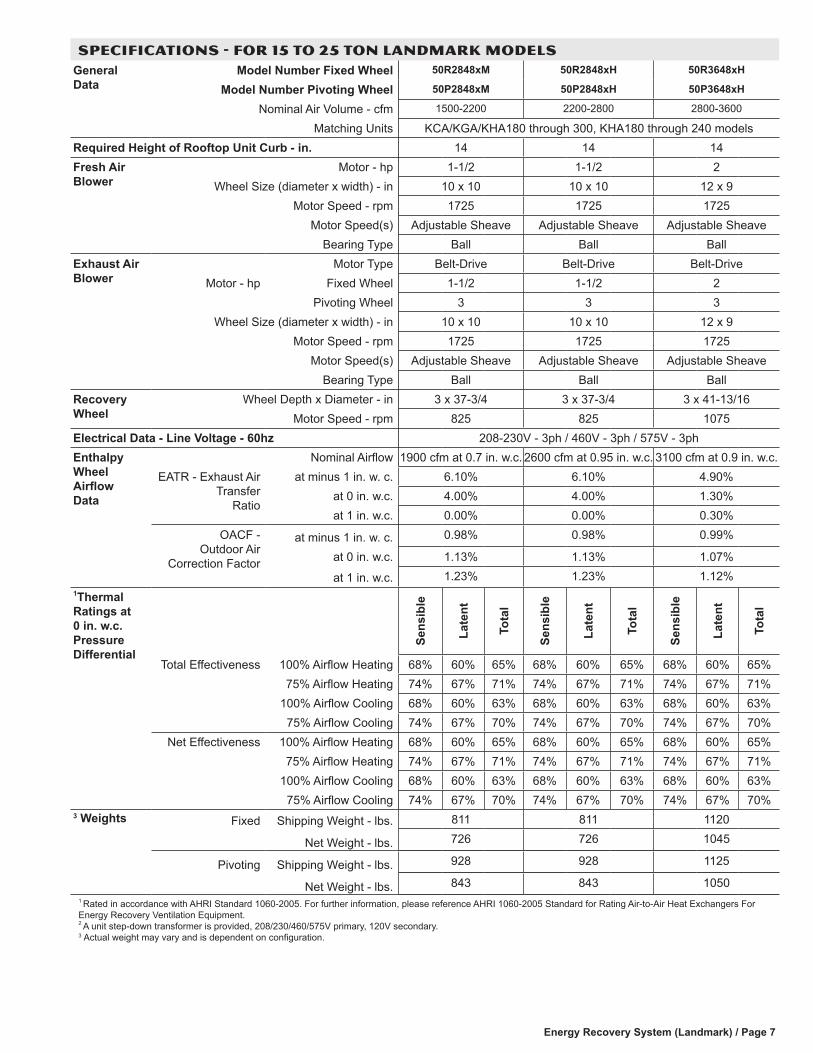
SPECIFICATIONS - FOR 15 TO 25 TON LANDMARK MODELSGeneral Data
Model Number Fixed Wheel 50R2848xM 50R2848xH 50R3648xH
Model Number Pivoting Wheel 50P2848xM 50P2848xH 50P3648xH
Nominal Air Volume - cfm 1500-2200 2200-2800 2800-3600
Matching Units KCA/KGA/KHA180 through 300, KHA180 through 240 modelsRequired Height of Rooftop Unit Curb - in. 14 14 14Fresh Air Blower
Motor - hp 1-1/2 1-1/2 2Wheel Size (diameter x width) - in 10 x 10 10 x 10 12 x 9
Motor Speed - rpm 1725 1725 1725Motor Speed(s) Adjustable Sheave Adjustable Sheave Adjustable Sheave
Bearing Type Ball Ball BallExhaust Air Blower
Motor Type Belt-Drive Belt-Drive Belt-DriveMotor - hp Fixed Wheel 1-1/2 1-1/2 2
Pivoting Wheel 3 3 3Wheel Size (diameter x width) - in 10 x 10 10 x 10 12 x 9
Motor Speed - rpm 1725 1725 1725Motor Speed(s) Adjustable Sheave Adjustable Sheave Adjustable Sheave
Bearing Type Ball Ball BallRecovery Wheel
Wheel Depth x Diameter - in 3 x 37-3/4 3 x 37-3/4 3 x 41-13/16Motor Speed - rpm 825 825 1075
Electrical Data - Line Voltage - 60hz 208-230V - 3ph / 460V - 3ph / 575V - 3phEnthalpy Wheel Airflow Data
Nominal Airflow 1900 cfm at 0.7 in. w.c. 2600 cfm at 0.95 in. w.c. 3100 cfm at 0.9 in. w.c.EATR - Exhaust Air
Transfer Ratio
at minus 1 in. w. c. 6.10% 6.10% 4.90%at 0 in. w.c. 4.00% 4.00% 1.30%at 1 in. w.c. 0.00% 0.00% 0.30%
OACF - Outdoor Air
Correction Factor
at minus 1 in. w. c. 0.98% 0.98% 0.99%
at 0 in. w.c. 1.13% 1.13% 1.07%
at 1 in. w.c. 1.23% 1.23% 1.12%1Thermal Ratings at 0 in. w.c. Pressure Differential
Sens
ible
Late
nt
Tota
l
Sens
ible
Late
nt
Tota
l
Sens
ible
Late
nt
Tota
l
Total Effectiveness 100% Airflow Heating 68% 60% 65% 68% 60% 65% 68% 60% 65%75% Airflow Heating 74% 67% 71% 74% 67% 71% 74% 67% 71%
100% Airflow Cooling 68% 60% 63% 68% 60% 63% 68% 60% 63%75% Airflow Cooling 74% 67% 70% 74% 67% 70% 74% 67% 70%
Net Effectiveness 100% Airflow Heating 68% 60% 65% 68% 60% 65% 68% 60% 65%75% Airflow Heating 74% 67% 71% 74% 67% 71% 74% 67% 71%
100% Airflow Cooling 68% 60% 63% 68% 60% 63% 68% 60% 63%75% Airflow Cooling 74% 67% 70% 74% 67% 70% 74% 67% 70%
3 Weights Fixed Shipping Weight - lbs. 811 811 1120
Net Weight - lbs. 726 726 1045
Pivoting Shipping Weight - lbs. 928 928 1125
Net Weight - lbs. 843 843 10501 Rated in accordance with AHRI Standard 1060-2005. For further information, please reference AHRI 1060-2005 Standard for Rating Air-to-Air Heat Exchangers For Energy Recovery Ventilation Equipment. 2 A unit step-down transformer is provided, 208/230/460/575V primary, 120V secondary.3 Actual weight may vary and is dependent on configuration.
Energy Recovery System (Landmark) / Page 8
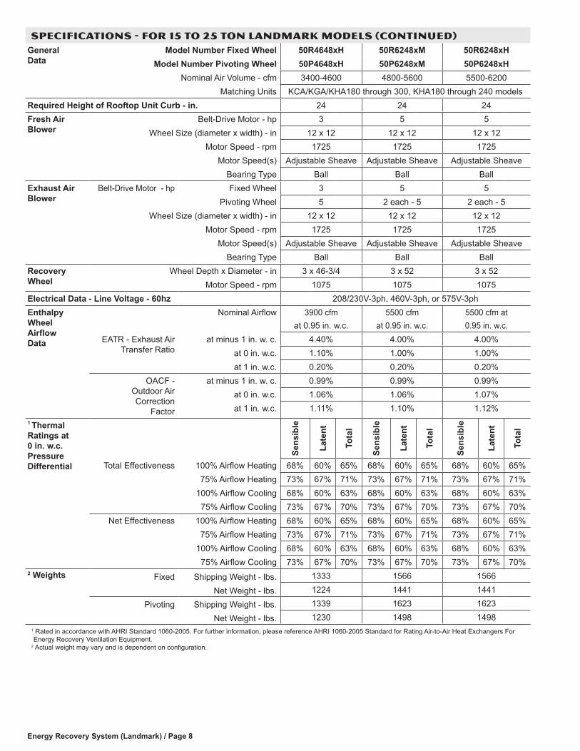
SPECIFICATIONS - FOR 15 TO 25 TON LANDMARK MODELS (CONTINUED) General Data
Model Number Fixed Wheel 50R4648xH 50R6248xM 50R6248xHModel Number Pivoting Wheel 50P4648xH 50P6248xM 50P6248xH
Nominal Air Volume - cfm 3400-4600 4800-5600 5500-6200Matching Units KCA/KGA/KHA180 through 300, KHA180 through 240 models
Required Height of Rooftop Unit Curb - in. 24 24 24Fresh Air Blower
Belt-Drive Motor - hp 3 5 5Wheel Size (diameter x width) - in 12 x 12 12 x 12 12 x 12
Motor Speed - rpm 1725 1725 1725Motor Speed(s) Adjustable Sheave Adjustable Sheave Adjustable Sheave
Bearing Type Ball Ball BallExhaust Air Blower
Belt-Drive Motor - hp Fixed Wheel 3 5 5Pivoting Wheel 5 2 each - 5 2 each - 5
Wheel Size (diameter x width) - in 12 x 12 12 x 12 12 x 12Motor Speed - rpm 1725 1725 1725
Motor Speed(s) Adjustable Sheave Adjustable Sheave Adjustable SheaveBearing Type Ball Ball Ball
Recovery Wheel
Wheel Depth x Diameter - in 3 x 46-3/4 3 x 52 3 x 52Motor Speed - rpm 1075 1075 1075
Electrical Data - Line Voltage - 60hz 208/230V-3ph, 460V-3ph, or 575V-3phEnthalpy Wheel Airflow Data
Nominal Airflow 3900 cfmat 0.95 in. w.c.
5500 cfmat 0.95 in. w.c.
5500 cfm at0.95 in. w.c.
EATR - Exhaust Air Transfer Ratio
at minus 1 in. w. c. 4.40% 4.00% 4.00%at 0 in. w.c. 1.10% 1.00% 1.00%at 1 in. w.c. 0.20% 0.20% 0.20%
OACF - Outdoor Air Correction
Factor
at minus 1 in. w. c. 0.99% 0.99% 0.99%at 0 in. w.c. 1.06% 1.06% 1.07%at 1 in. w.c. 1.11% 1.10% 1.12%
1 Thermal Ratings at 0 in. w.c. Pressure Differential
Sens
ible
Late
nt
Tota
l
Sens
ible
Late
nt
Tota
l
Sens
ible
Late
nt
Tota
l
Total Effectiveness 100% Airflow Heating 68% 60% 65% 68% 60% 65% 68% 60% 65%75% Airflow Heating 73% 67% 71% 73% 67% 71% 73% 67% 71%
100% Airflow Cooling 68% 60% 63% 68% 60% 63% 68% 60% 63%75% Airflow Cooling 73% 67% 70% 73% 67% 70% 73% 67% 70%
Net Effectiveness 100% Airflow Heating 68% 60% 65% 68% 60% 65% 68% 60% 65%75% Airflow Heating 73% 67% 71% 73% 67% 71% 73% 67% 71%
100% Airflow Cooling 68% 60% 63% 68% 60% 63% 68% 60% 63%75% Airflow Cooling 73% 67% 70% 73% 67% 70% 73% 67% 70%
2 Weights Fixed Shipping Weight - lbs. 1333 1566 1566
Net Weight - lbs. 1224 1441 1441
Pivoting Shipping Weight - lbs. 1339 1623 1623
Net Weight - lbs. 1230 1498 14981 Rated in accordance with AHRI Standard 1060-2005. For further information, please reference AHRI 1060-2005 Standard for Rating Air-to-Air Heat Exchangers For Energy Recovery Ventilation Equipment.
2 Actual weight may vary and is dependent on configuration.
Energy Recovery System (Landmark) / Page 9
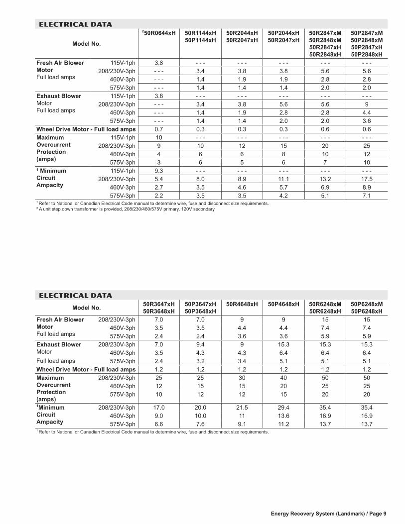
ELECTRICAL DATA
Model No.
250R0644xH 50R1144xH 50P1144xH
50R2044xH 50R2047xH
50P2044xH 50R2047xH
50R2847xM 50R2848xM 50R2847xH 50R2848xH
50P2847xM 50P2848xM 50P2847xH 50P2848xH
Fresh AIr Blower Motor Full load amps
115V-1ph 3.8 - - - - - - - - - - - - - - -208/230V-3ph - - - 3.4 3.8 3.8 5.6 5.6
460V-3ph - - - 1.4 1.9 1.9 2.8 2.8575V-3ph - - - 1.4 1.4 1.4 2.0 2.0
Exhaust Blower Motor Full load amps
115V-1ph 3.8 - - - - - - - - - - - - - - -208/230V-3ph - - - 3.4 3.8 5.6 5.6 9
460V-3ph - - - 1.4 1.9 2.8 2.8 4.4575V-3ph - - - 1.4 1.4 2.0 2.0 3.6
Wheel Drive Motor - Full load amps 0.7 0.3 0.3 0.3 0.6 0.6Maximum Overcurrent Protection (amps)
115V-1ph 10 - - - - - - - - - - - - - - -208/230V-3ph 9 10 12 15 20 25
460V-3ph 4 6 6 8 10 12575V-3ph 3 6 5 6 7 10
1 Minimum Circuit Ampacity
115V-1ph 9.3 - - - - - - - - - - - - - - -208/230V-3ph 5.4 8.0 8.9 11.1 13.2 17.5
460V-3ph 2.7 3.5 4.6 5.7 6.9 8.9575V-3ph 2.2 3.5 3.5 4.2 5.1 7.1
1 Refer to National or Canadian Electrical Code manual to determine wire, fuse and disconnect size requirements.2 A unit step down transformer is provided, 208/230/460/575V primary, 120V secondary
ELECTRICAL DATA
Model No. 50R3647xH 50R3648xH
50P3647xH 50P3648xH
50R4648xH 50P4648xH 50R6248xM 50R6248xH
50P6248xM 50P6248xH
Fresh AIr Blower Motor Full load amps
208/230V-3ph 7.0 7.0 9 9 15 15460V-3ph 3.5 3.5 4.4 4.4 7.4 7.4575V-3ph 2.4 2.4 3.6 3.6 5.9 5.9
Exhaust Blower MotorFull load amps
208/230V-3ph 7.0 9.4 9 15.3 15.3 15.3460V-3ph 3.5 4.3 4.3 6.4 6.4 6.4575V-3ph 2.4 3.2 3.4 5.1 5.1 5.1
Wheel Drive Motor - Full load amps 1.2 1.2 1.2 1.2 1.2 1.2Maximum Overcurrent Protection (amps)
208/230V-3ph 25 25 30 40 50 50460V-3ph 12 15 15 20 25 25575V-3ph 10 12 12 15 20 20
1Minimum Circuit Ampacity
208/230V-3ph 17.0 20.0 21.5 29.4 35.4 35.4460V-3ph 9.0 10.0 11 13.6 16.9 16.9575V-3ph 6.6 7.6 9.1 11.2 13.7 13.7
1 Refer to National or Canadian Electrical Code manual to determine wire, fuse and disconnect size requirements.
Energy Recovery System (Landmark) / Page 10
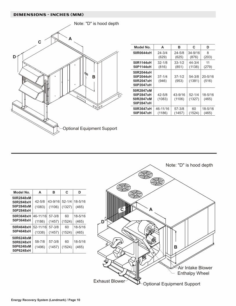
DIMENSIONS - INCHES (MM)
Optional Equipment Support
CA
B
D
Note: "D" is hood depth
C A
B
Air Intake Blower
D
Enthalpy Wheel
Optional Equipment Support
Note: "D" is hood depth
Exhaust Blower
Model No. A B C D50R0644xH 24-3/4
(629)24-5/8 (625)
34-9/16 (876)
8 (203)
50R1144xH 50P1144xH
32-1/8 (816)
33-1/2 (851)
44-3/4 (1138)
11 (279)
50R2044xH 50P2044xH 50R2047xH 50P2047xH
37-1/4 (946)
37-1/2 (953)
54-3/8 (1381)
20-5/16 (516)
50R2847xM 50P2847xH 50R2847xM 50P2847xH
42-5/8 (1083)
43-9/16 (1106)
52-1/4 (1327)
18-5/16 (465)
50R3647xH 50P3647xH
46-11/16 (1186)
57-3/8 (1457)
60 (1524)
18-5/16 (465)
Model No. A B C D50R2848xM 50R2848xH 50P2848xM 50P2848xH
42-5/8(1083)
43-9/16(1106)
52-1/4(1327)
18-5/16(465)
50R3648xH 50P3648xH
46-11/16(1186)
57-3/8(1457)
60(1524)
18-5/16(465)
50R4648xH 50P4648xH
52-11/16(1338)
57-3/8(1457)
60(1524)
18-5/16(465)
50R6248xM 50R6248xH 50P6248xM 50P6248xH
58-7/8(1496)
57-3/8(1457)
60(1524)
18-5/16(465)
Energy Recovery System (Landmark) / Page 11
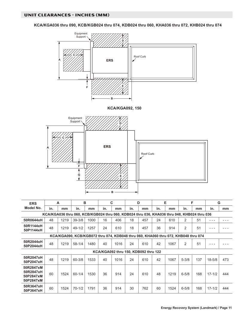
UNIT CLEARANCES - INCHES (MM)
A
F
B
Roof Curb
EquipmentSupport
ERS
D
E
C
G
F
ERS
EquipmentSupport
Roof Curb
B
A
D
C
E
KCA/KGA036 thru 090, KCB/KGB024 thru 074, KDB024 thru 060, KHA036 thru 072, KHB024 thru 074
KCA/KGA092, 150
ERS Model No.
A B C D E F Gin. mm in. mm in. mm in. mm in. mm in. mm in. mm
KCA/KGA036 thru 060, KCB/KGB024 thru 060, KDB024 thru 036, KHA036 thru 048, KHB024 thru 03650R0644xH 48 1219 39-3/8 1000 16 406 18 457 24 610 2 51 - - - - - -50R1144xH 50P1144xH 48 1219 49-1/2 1257 24 610 18 457 36 914 2 51 - - - - - -
KCA/KGA090, KCB/KGB072 thru 074, KDB048 thru 060, KHA060 thru 072, KHB048 thru 07450R2044xH 50P2044xH 48 1219 58-1/4 1480 40 1016 24 610 42 1067 2 51 - - - - - -
KCA/KGA092 thru 150, KDB092 thru 12250R2047xH 50P2047xH 48 1219 60-3/8 1533 40 1016 24 610 42 1067 5-3/8 137 18-5/8 473
50R2847xM 50R2847xH 50P2847xM 50P2847xM
60 1524 60-1/4 1530 36 914 24 610 48 1219 6-5/8 168 17-1/2 444
50R3647xH 50P3647xH 60 1524 70-1/2 1791 36 914 30 762 60 1524 6-5/8 168 17-1/2 444
Energy Recovery System (Landmark) / Page 12
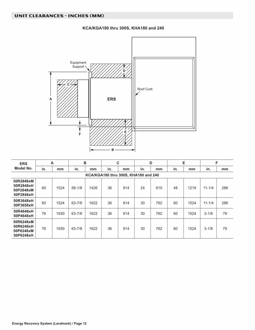
UNIT CLEARANCES - INCHES (MM)
F
A
C
E
EquipmentSupport
B
Roof Curb
ERS
D
KCA/KGA180 thru 300S, KHA180 and 240
ERS Model No.
A B C D E Fin. mm in. mm in. mm in. mm in. mm in. mm
KCA/KGA180 thru 300S, KHA180 and 24050R2848xM 50R2848xH 50P2848xM 50P2848xH
60 1524 56-1/8 1426 36 914 24 610 48 1219 11-1/4 286
50R3648xH 50P3658xH 60 1524 63-7/8 1622 36 914 30 762 60 1524 11-1/4 286
50R4648xH 50P4648xH 76 1930 63-7/8 1622 36 914 30 762 60 1524 3-1/8 79
50R6248xM 50R6248xH 50P6248xM 50P6248xH
76 1930 63-7/8 1622 36 914 30 762 60 1524 3-1/8 79
Energy Recovery System (Landmark) / Page 13
GUIDE SPECIFICATIONS
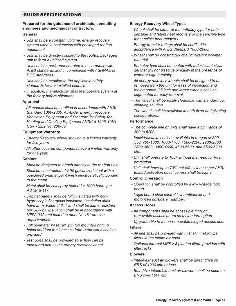
Prepared for the guidance of architects, consulting engineers and mechanical contractors. General- Unit shall be a constant volume, energy recovery
system used in conjunction with packaged rooftop equipment.
- Unit shall be directly coupled to the rooftop packaged unit to form a unitized system.
- Unit shall be performance rated in accordance with AHRI standards and in compliance with ASHRAE or DOE standards.
- Unit shall be certified to the applicable safety standards for the installed country.
- In addition, manufacturer shall test operate system at the factory before shipment.
Approval- All models shall be certified in accordance with AHRI
Standard 1060-2005, Air-to-Air Energy Recovery Ventilation Equipment and Standard for Safety for Heating and Cooling Equipment ANSI/UL1995, CAN CSA - 22.2 No. 236-05
Equipment Warranty- Energy Recovery wheel shall have a limited warranty
for five years.- All other covered components have a limited warranty
for one year.Cabinet- Shall be designed to attach directly to the rooftop unit.- Shall be constructed of G90 galvanized steel with a
powdered enamel paint finish electrostatically bonded to the metal.
- Metal shall be salt spray tested for 1000 hours per ASTM B-117.
- Cabinet panels shall be fully insulated with non-hygroscopic fiberglass insulation. Insulation shall have an R-Value of 3. 7 and shall be flame resistant per UL-723. Insulation shall be in accordance with NFPA 90A and tested to meet UL 181 erosion requirements.
- Full perimeter base rail with top mounted rigging holes and fork truck access from three sides shall be provided.
- Test ports shall be provided so airflow can be measured across the energy recovery wheel.
Energy Recovery Wheel Types- Wheel shall be either of the enthalpy type for both
sensible and latent heat recovery or the sensible type for sensible heat recovery.
- Energy transfer ratings shall be certified in accordance with AHRI Standard 1060-2000.
- Wheel shall be constructed of a lightweight polymer material.
- Enthalpy type shall be coated with a desiccant silica gel that will not dissolve or liquify in the presence of water or high humidity.
- All energy recovery wheels shall be designed to be removed from the unit for ease of inspection and maintenance, 25 inch and larger wheels shall be segmented for easy removal.
- The wheel shall be easily cleanable with standard coil cleaning solution.
- The wheel shall be available in both fixed and pivoting configurations.
Performance- The complete line of units shall have a cfm range of
300 to 6200.- Individual units shall be available in ranges of 300
550, 700-1000, 1000-1700, 1500-2200, 2200-2800, 2800-3600, 3400-4600, 4800-5600, and 5500-6200 cfm.
- Unit shall operate to 10oF without the need for frost protection.
- Unit shall have up to 73% net effectiveness per AHRI tests. Application effectiveness shall be higher.
Control Operation- Operation shall be controlled by a low voltage logic
board.- Logic board shall control low ambient kit and
motorized outside air damper.Access Doors- All components shall be accessible through
removable access doors as a standard option.- Upgradeable to a non-removable hinged access door.
Filters- All unit shall be provided with mist eliminator type
filters in the intake air hood.- Optional internal MERV 8 pleated filters provided with
filter racks.Blowers- Intake/exhaust air blowers shall be direct drive on
ERS of 1000 cfm or less.- Belt drive intake/exhaust air blowers shall be used on
ERS over 1000 cfm.
Energy Recovery System (Landmark) / Page 14
GUIDE SPECIFICATIONS
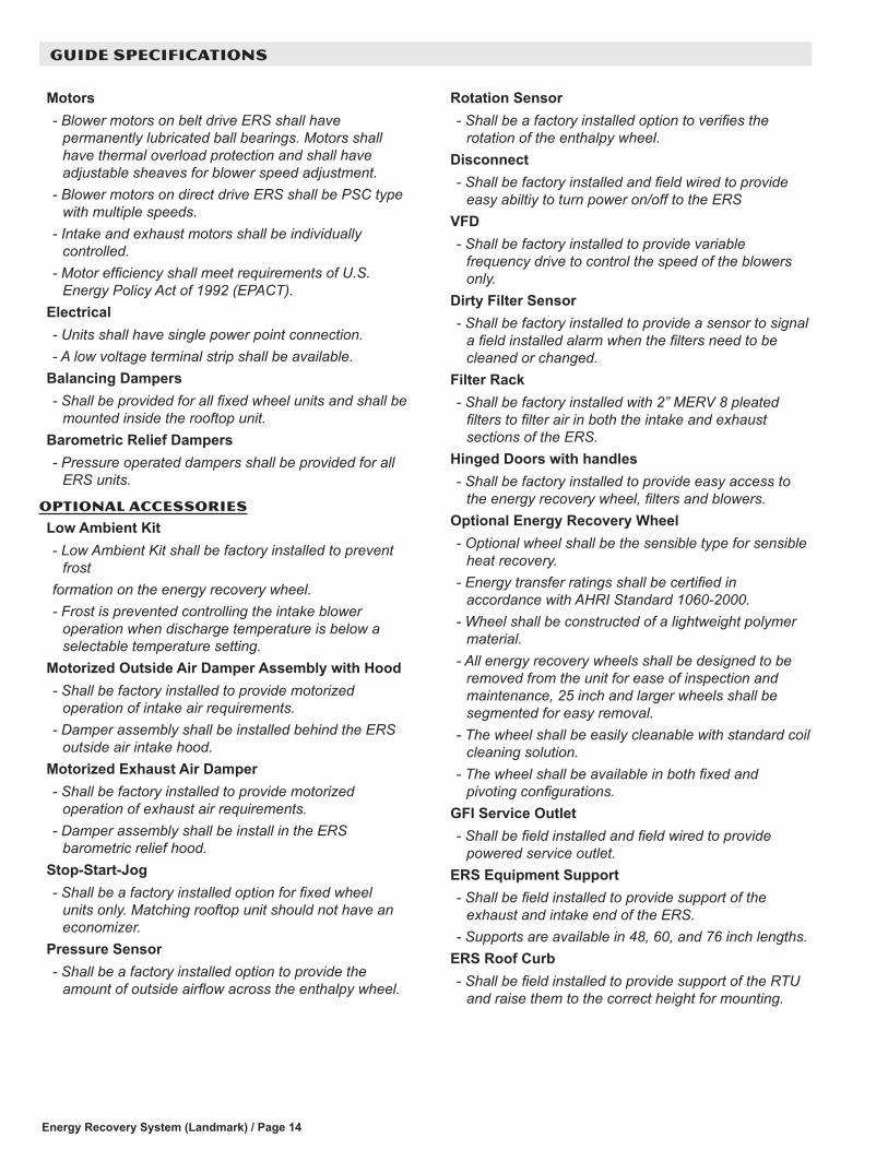
Motors- Blower motors on belt drive ERS shall have
permanently lubricated ball bearings. Motors shall have thermal overload protection and shall have adjustable sheaves for blower speed adjustment.
- Blower motors on direct drive ERS shall be PSC type with multiple speeds.
- Intake and exhaust motors shall be individually controlled.
- Motor efficiency shall meet requirements of U.S. Energy Policy Act of 1992 (EPACT).
Electrical- Units shall have single power point connection.- A low voltage terminal strip shall be available.
Balancing Dampers- Shall be provided for all fixed wheel units and shall be
mounted inside the rooftop unit.Barometric Relief Dampers- Pressure operated dampers shall be provided for all
ERS units.
OPTIONAL ACCESSORIES
Low Ambient Kit- Low Ambient Kit shall be factory installed to prevent
frostformation on the energy recovery wheel.- Frost is prevented controlling the intake blower
operation when discharge temperature is below a selectable temperature setting.
Motorized Outside Air Damper Assembly with Hood- Shall be factory installed to provide motorized
operation of intake air requirements.- Damper assembly shall be installed behind the ERS
outside air intake hood.Motorized Exhaust Air Damper- Shall be factory installed to provide motorized
operation of exhaust air requirements.- Damper assembly shall be install in the ERS
barometric relief hood.Stop-Start-Jog- Shall be a factory installed option for fixed wheel
units only. Matching rooftop unit should not have an economizer.
Pressure Sensor- Shall be a factory installed option to provide the
amount of outside airflow across the enthalpy wheel.
Rotation Sensor- Shall be a factory installed option to verifies the
rotation of the enthalpy wheel.Disconnect- Shall be factory installed and field wired to provide
easy abiltiy to turn power on/off to the ERSVFD- Shall be factory installed to provide variable
frequency drive to control the speed of the blowers only.
Dirty Filter Sensor- Shall be factory installed to provide a sensor to signal
a field installed alarm when the filters need to be cleaned or changed.
Filter Rack- Shall be factory installed with 2” MERV 8 pleated
filters to filter air in both the intake and exhaust sections of the ERS.
Hinged Doors with handles- Shall be factory installed to provide easy access to
the energy recovery wheel, filters and blowers.Optional Energy Recovery Wheel- Optional wheel shall be the sensible type for sensible
heat recovery.- Energy transfer ratings shall be certified in
accordance with AHRI Standard 1060-2000.- Wheel shall be constructed of a lightweight polymer
material.- All energy recovery wheels shall be designed to be
removed from the unit for ease of inspection and maintenance, 25 inch and larger wheels shall be segmented for easy removal.
- The wheel shall be easily cleanable with standard coil cleaning solution.
- The wheel shall be available in both fixed and pivoting configurations.
GFI Service Outlet- Shall be field installed and field wired to provide
powered service outlet.ERS Equipment Support- Shall be field installed to provide support of the
exhaust and intake end of the ERS.- Supports are available in 48, 60, and 76 inch lengths.
ERS Roof Curb- Shall be field installed to provide support of the RTU
and raise them to the correct height for mounting.

NOTE - Due to Lennox’ ongoing commitment to quality, Specifications, Ratings and Dimensions subject to change without notice and without incurring liability. Improper installation, adjustment, alteration, service or maintenance can cause property damage or personal injury. Installation and service must be performed by a qualified installer and servicing agency. ©2017 Lennox Industries, Inc.
Visit us at www.lennox.com For the latest technical information, www.lennoxcommercial.com Contact us at 1-800-4-LENNOX
REVISIONS
Sections Description of Change
Document
Removed 50R0645, 50P0645, 50R1146, 50P1146, 50R2046 and 50P2046 models.Landmark economizer cabinet changes now require the use of 50R0644, 50R1144, 50P1144 for 024-090 models and 50R2044, 50P2044 sizes for 072-074 models.Added usage for KCB/KGB/KHB and KDB models
REVISIONS