Embed Size (px)
Citation preview
Desirée Wolfgramm
Columbia Generating Station
P.O. Box 968, PE20
Richland, WA 99352-0968
Ph. 509-377-4792
GO2-20-081
U.S. Nuclear Regulatory Commission ATTN: Document Control Desk Washington, D.C. 20555-0001
Subject: COLUMBIA GENERATING STATION, DOCKET NO. 50-397; CYCLE 25 CORE OPERATING LIMITS REPORT, REVISION 1
Dear Sir or Madam:
In accordance with Columbia Generating Station Technical Specification (TS) 5.6.3.d, Energy Northwest herewith submits the Cycle 25 Core Operating Limits Report (COLR), Revision 1. The operating limits in the COLR revision were developed in accordance with the requirements of TS 5.6.3.a, b, and c. The changes to the COLR have been reviewed by the Columbia Generating Station Plant Operations Committee.
No new regulatory commitments are made in this letter. If you have any questions or require additional information, please contact Mr. R. M. Garcia, Licensing Supervisor, at (509) 377-8463.
Executed on this ______ day of __________, 2020.
Respectfully,
D. M. WolfgrammManager, Regulatory Affairs
Enclosure � as stated
cc: NRC Region IV Regional Admin NRC Region IV PM NRC Senior Resident Inspector C.D. Sonoda � BPA (w/o enc)
May 20, 2020
ENERGY NORTHWEST
GO2-20-081 Enclosure
Core Operating Limits Report Columbia Generating Station Cycle 25, Revision 1
March 2020
Columbia Generating Station Page 1 COLR-01, Revision 25.1
CORE OPERATING LIMITS REPORT COLUMBIA GENERATING STATION CYCLE 25
Revision 25.1
March 2020
r + + +l+I+ I- + + + +lt l+
r,- +-t- + + ;-.:.... r + + ~ + , ++ ++ i" t-+ ++ + ...I .... ++ ++ li + + ++ + -++ T-,. = + + t- ...
~ ~
+ + ++ -L. + + + ..J.. + + '--"
t- + ;- + +l+T+ L + + -t- 1+1+
+ + n + + +H + + + +
+ I+ + ++ + ++ + + + + + + +
= ++
a~ + + + + + +
++ + + + + H + .. .J
T + -, + + + + + + ++ + + + + + + + .J ..L
ENERGY NORTHWEST
Columbia Generating Station Page 2 COLR-01, Revision 25.1
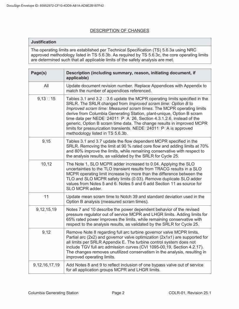
DESCRIPTION OF CHANGES
Justification
The operating limits are established per Technical Specification (TS) 5.6.3a using NRC approved methodology listed in TS 5.6.3b. As required by TS 5.6.3c, the core operating limits are determined such that all applicable limits of the safety analysis are met.
Page(s) Description (including summary, reason, initiating document, if applicable)
All Update document revision number. Replace Appendices with Appendix to match the number of appendices referenced.
9,13 – 15 Tables 3.1 and 3.2 – 3.6 update the MCPR operating limits specified in the SRLR. The SRLR changed from Improved scram time: Option B to Improved scram time: Measured scram times. The MCPR operating limits
derive from Columbia Generating Station, plant-unique, Option B scram time data per NEDE–24011–P–A–26, Section 4.3.1.2.6, instead of the generic, Option B scram time data. The change results in improved MCPR limits for pressurization transients. NEDE–24011–P–A is approved methodology listed in TS 5.6.3b.
9,15 Tables 3.1 and 3.7 update the flow dependent MCPR specified in the SRLR. Removing the limit at 90 % rated core flow and adding limits at 70% and 80% improve the limits, while remaining conservative with respect to the analysis results, as validated by the SRLR for Cycle 25.
10,12 The Note 1, SLO MCPR adder increased to 0.04. Applying the SLO uncertainties to the TLO transient results from TRACG results in a SLO MCPR operating limit increase by more than the difference between the TLO and SLO MCPR safety limits (0.03). Remove duplicate SLO adder values from Notes 5 and 6. Notes 5 and 6 add Section 11 as source for SLO MCPR adder.
11 Update mean scram time to Notch 39 and standard deviation used in the Option B analysis (measured scram times).
9,12,15,19 Notes 7 and 10 describe the power dependent behavior of the revised pressure regulator out of service MCPR and LHGR limits. Adding limits for 65% rated power improves the limits, while remaining conservative with respect to the analysis results, as validated by the SRLR for Cycle 25.
9,12 Remove Note 8 regarding full arc turbine governor valve MCPR limits. Partial arc (2x2) and governor valve optimization (2x1x1) are supported for all limits per SRLR Appendix E. The turbine control system does not include TGV full arc admission curves (CVI 1095-00,19, Section 4.2.17). The changes removes unutilized conservatism in the analysis, resulting in improved operating limits.
9,12,16,17,19 Add Notes 8 and 9 to reflect inclusion of one bypass valve out of service for all application groups MCPR and LHGR limits.
Columbia Generating Station Page 3 COLR-01, Revision 25.1
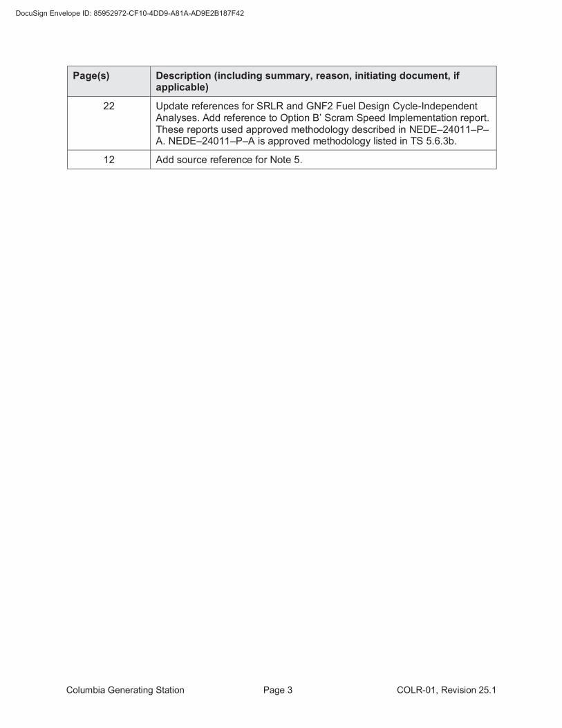
Page(s) Description (including summary, reason, initiating document, if applicable)
22 Update references for SRLR and GNF2 Fuel Design Cycle-Independent Analyses. Add reference to Option B’ Scram Speed Implementation report. These reports used approved methodology described in NEDE–24011–P–A. NEDE–24011–P–A is approved methodology listed in TS 5.6.3b.
12 Add source reference for Note 5.
Columbia Generating Station Page 4 COLR-01, Revision 25.1
Table of Contents
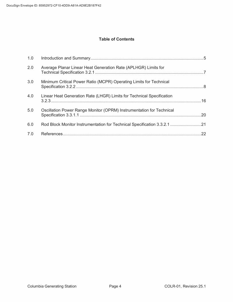
1.0 Introduction and Summary ............................................................................................... 5
2.0 Average Planar Linear Heat Generation Rate (APLHGR) Limits for Technical Specification 3.2.1 ........................................................................................... 7
3.0 Minimum Critical Power Ratio (MCPR) Operating Limits for Technical Specification 3.2.2 ........................................................................................................... 8
4.0 Linear Heat Generation Rate (LHGR) Limits for Technical Specification 3.2.3 .............................................................................................................................. 16
5.0 Oscillation Power Range Monitor (OPRM) Instrumentation for Technical Specification 3.3.1.1 ...................................................................................................... 20
6.0 Rod Block Monitor Instrumentation for Technical Specification 3.3.2.1 .......................... 21
7.0 References .................................................................................................................... 22
Columbia Generating Station Page 5 COLR-01, Revision 25.1
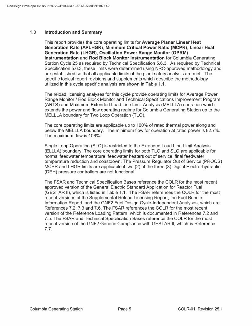
1.0 Introduction and Summary
This report provides the core operating limits for Average Planar Linear Heat Generation Rate (APLHGR), Minimum Critical Power Ratio (MCPR), Linear Heat Generation Rate (LHGR), Oscillation Power Range Monitor (OPRM) Instrumentation and Rod Block Monitor Instrumentation for Columbia Generating Station Cycle 25 as required by Technical Specification 5.6.3. As required by Technical Specification 5.6.3, these limits were determined using NRC-approved methodology and are established so that all applicable limits of the plant safety analysis are met. The specific topical report revisions and supplements which describe the methodology utilized in this cycle specific analysis are shown in Table 1.1.
The reload licensing analyses for this cycle provide operating limits for Average Power Range Monitor / Rod Block Monitor and Technical Specifications Improvement Program (ARTS) and Maximum Extended Load Line Limit Analysis (MELLLA) operation which extends the power and flow operating regime for Columbia Generating Station up to the MELLLA boundary for Two Loop Operation (TLO).
The core operating limits are applicable up to 100% of rated thermal power along and below the MELLLA boundary. The minimum flow for operation at rated power is 82.7%. The maximum flow is 106%.
Single Loop Operation (SLO) is restricted to the Extended Load Line Limit Analysis (ELLLA) boundary. The core operating limits for both TLO and SLO are applicable for normal feedwater temperature, feedwater heaters out of service, final feedwater temperature reduction and coastdown. The Pressure Regulator Out of Service (PROOS) MCPR and LHGR limits are applicable if two (2) of the three (3) Digital Electro-hydraulic (DEH) pressure controllers are not functional.
The FSAR and Technical Specification Bases reference the COLR for the most recent approved version of the General Electric Standard Application for Reactor Fuel (GESTAR II), which is listed in Table 1.1. The FSAR references the COLR for the most recent versions of the Supplemental Reload Licensing Report, the Fuel Bundle Information Report, and the GNF2 Fuel Design Cycle-Independent Analyses, which are References 7.2, 7.3 and 7.6. The FSAR references the COLR for the most recent version of the Reference Loading Pattern, which is documented in References 7.2 and 7.5. The FSAR and Technical Specification Bases reference the COLR for the most recent version of the GNF2 Generic Compliance with GESTAR II, which is Reference 7.7.
Columbia Generating Station Page 6 COLR-01, Revision 25.1
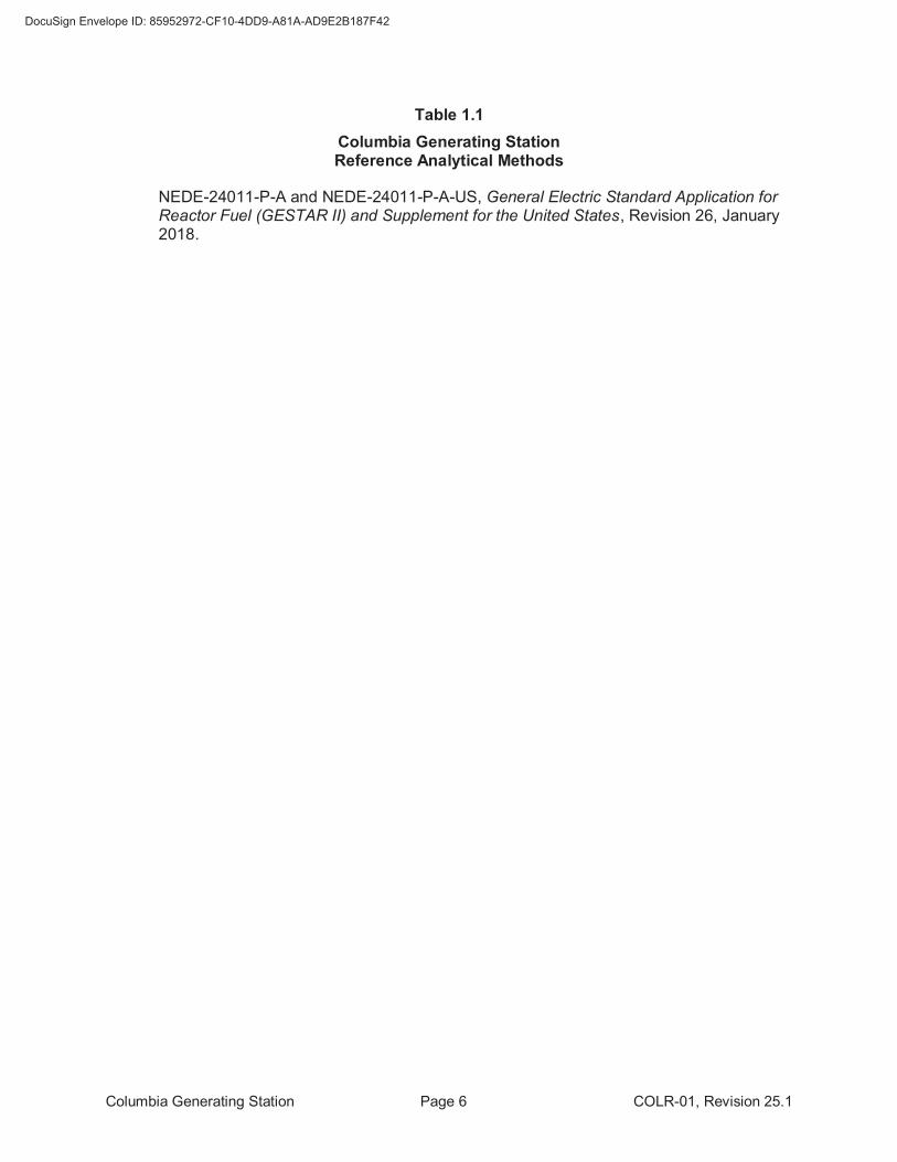
Table 1.1
Columbia Generating Station Reference Analytical Methods
NEDE-24011-P-A and NEDE-24011-P-A-US, General Electric Standard Application for Reactor Fuel (GESTAR II) and Supplement for the United States, Revision 26, January 2018.
Columbia Generating Station Page 7 COLR-01, Revision 25.1
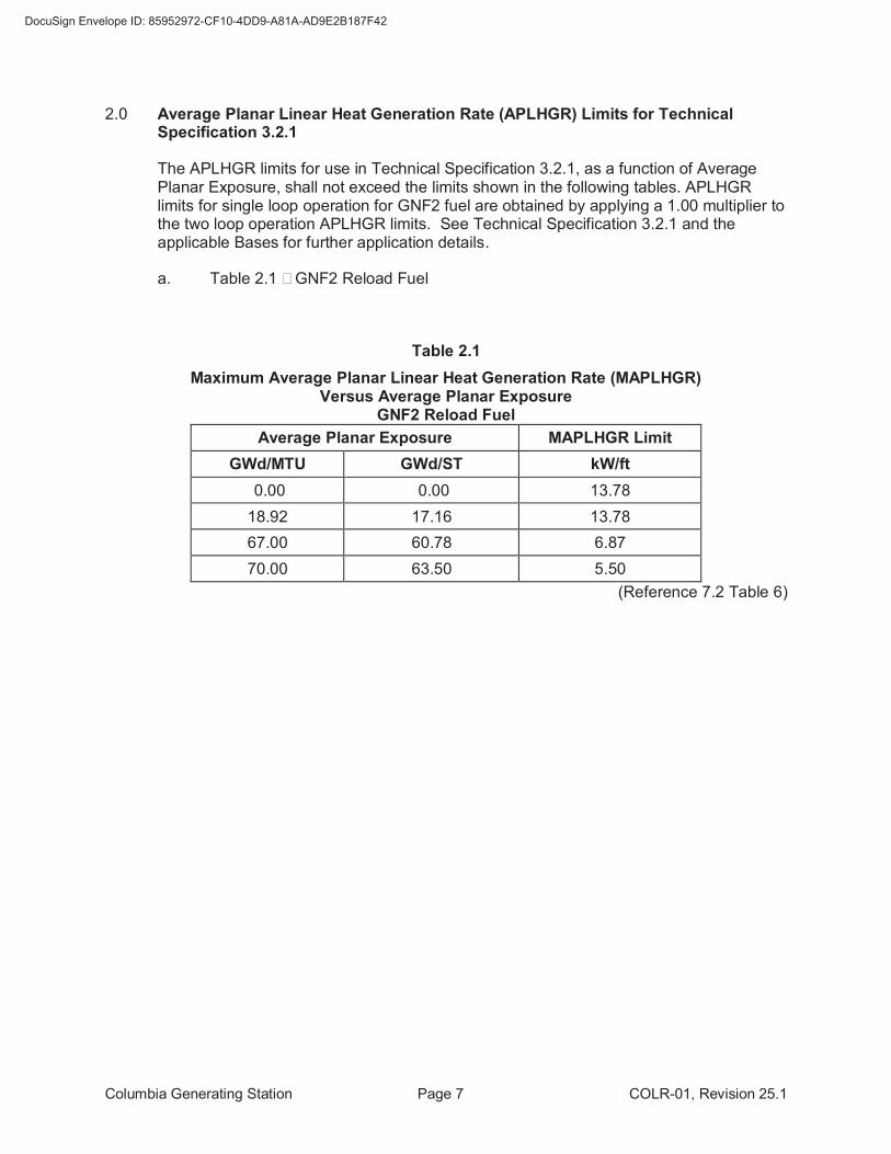
2.0 Average Planar Linear Heat Generation Rate (APLHGR) Limits for Technical Specification 3.2.1
The APLHGR limits for use in Technical Specification 3.2.1, as a function of Average Planar Exposure, shall not exceed the limits shown in the following tables. APLHGR limits for single loop operation for GNF2 fuel are obtained by applying a 1.00 multiplier to the two loop operation APLHGR limits. See Technical Specification 3.2.1 and the applicable Bases for further application details.
a. Table 2.1 – GNF2 Reload Fuel
Table 2.1
Maximum Average Planar Linear Heat Generation Rate (MAPLHGR) Versus Average Planar Exposure
GNF2 Reload Fuel
Average Planar Exposure MAPLHGR Limit
GWd/MTU GWd/ST kW/ft
0.00 0.00 13.78
18.92 17.16 13.78
67.00 60.78 6.87
70.00 63.50 5.50
(Reference 7.2 Table 6)
Columbia Generating Station Page 8 COLR-01, Revision 25.1
3.0 Minimum Critical Power Ratio (MCPR) Operating Limits for Technical Specification 3.2.2
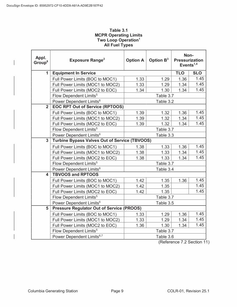
The MCPR operating limits for use in Technical Specification 3.2.2 are determined by the larger of the flow dependent (MCPRf) and power dependent (MCPRp) limits from Table 3.1 through Table 3.7. See Technical Specification 3.2.2 and the applicable Bases for further application details.
The MCPR99.9% values used to calculate the MCPR operating limits are 1.10 for two loop operation (TLO) and 1.13 for single loop operation (SLO).
Columbia Generating Station Page 9 COLR-01, Revision 25.1
Table 3.1 MCPR Operating Limits Two Loop Operation1
All Fuel Types
Appl. Group8
Exposure Range2 Option A Option B3 Non-
Pressurization Events1,4
1 Equipment In Service TLO SLO
Full Power Limits (BOC to MOC1) 1.33 1.29 1.36 1.45
Full Power Limits (MOC1 to MOC2) 1.33 1.29 1.34 1.45
Full Power Limits (MOC2 to EOC) 1.34 1.30 1.34 1.45
Flow Dependent Limits5 Table 3.7
Power Dependent Limits6 Table 3.2
2 EOC RPT Out of Service (RPTOOS)
Full Power Limits (BOC to MOC1) 1.39 1.32 1.36 1.45
Full Power Limits (MOC1 to MOC2) 1.39 1.32 1.34 1.45
Full Power Limits (MOC2 to EOC) 1.39 1.32 1.34 1.45
Flow Dependent Limits5 Table 3.7
Power Dependent Limits6 Table 3.3
3 Turbine Bypass Valves Out of Service (TBVOOS)
Full Power Limits (BOC to MOC1) 1.38 1.33 1.36 1.45
Full Power Limits (MOC1 to MOC2) 1.38 1.33 1.34 1.45
Full Power Limits (MOC2 to EOC) 1.38 1.33 1.34 1.45
Flow Dependent Limits5 Table 3.7
Power Dependent Limits6 Table 3.4
4 TBVOOS and RPTOOS
Full Power Limits (BOC to MOC1) 1.42 1.35 1.36 1.45
Full Power Limits (MOC1 to MOC2) 1.42 1.35 1.45
Full Power Limits (MOC2 to EOC) 1.42 1.35 1.45
Flow Dependent Limits5 Table 3.7
Power Dependent Limits6 Table 3.5
5 Pressure Regulator Out of Service (PROOS)
Full Power Limits (BOC to MOC1) 1.33 1.29 1.36 1.45
Full Power Limits (MOC1 to MOC2) 1.33 1.29 1.34 1.45
Full Power Limits (MOC2 to EOC) 1.36 1.30 1.34 1.45
Flow Dependent Limits5 Table 3.7
Power Dependent Limits6,7 Table 3.6
(Reference 7.2 Section 11)
Columbia Generating Station Page 10 COLR-01, Revision 25.1
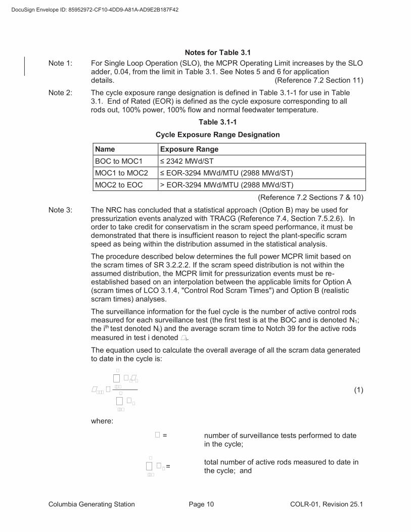
Notes for Table 3.1
Note 1: For Single Loop Operation (SLO), the MCPR Operating Limit increases by the SLO adder, 0.04, from the limit in Table 3.1. See Notes 5 and 6 for application details. (Reference 7.2 Section 11)
Note 2: The cycle exposure range designation is defined in Table 3.1-1 for use in Table 3.1. End of Rated (EOR) is defined as the cycle exposure corresponding to all rods out, 100% power, 100% flow and normal feedwater temperature.
Table 3.1-1
Cycle Exposure Range Designation
Name Exposure Range
BOC to MOC1 ≤ 2342 MWd/ST
MOC1 to MOC2 ≤ EOR-3294 MWd/MTU (2988 MWd/ST)
MOC2 to EOC > EOR-3294 MWd/MTU (2988 MWd/ST)
(Reference 7.2 Sections 7 & 10)
Note 3: The NRC has concluded that a statistical approach (Option B) may be used for pressurization events analyzed with TRACG (Reference 7.4, Section 7.5.2.6). In order to take credit for conservatism in the scram speed performance, it must be demonstrated that there is insufficient reason to reject the plant-specific scram speed as being within the distribution assumed in the statistical analysis.
The procedure described below determines the full power MCPR limit based on the scram times of SR 3.2.2.2. If the scram speed distribution is not within the assumed distribution, the MCPR limit for pressurization events must be re-established based on an interpolation between the applicable limits for Option A (scram times of LCO 3.1.4, "Control Rod Scram Times") and Option B (realistic scram times) analyses.
The surveillance information for the fuel cycle is the number of active control rods measured for each surveillance test (the first test is at the BOC and is denoted N1; the ith test denoted Ni) and the average scram time to Notch 39 for the active rods
measured in test i denoted t i.
The equation used to calculate the overall average of all the scram data generated to date in the cycle is:
å
å
=
==n
i
i
n
i
ii
ave
N
N
1
1
tt (1)
where:
n = number of surveillance tests performed to date in the cycle;
å=
n
i
iN1
= total number of active rods measured to date in the cycle; and
Columbia Generating Station Page 11 COLR-01, Revision 25.1
å=
n
i
iiN1
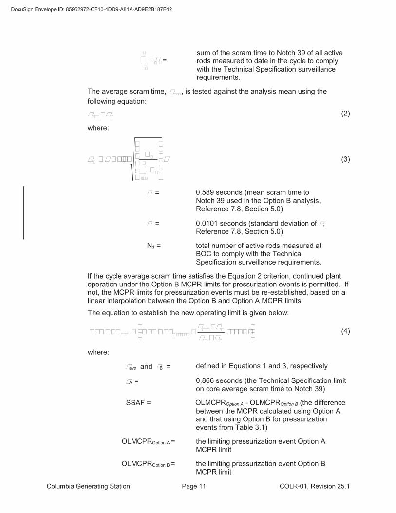
t = sum of the scram time to Notch 39 of all active rods measured to date in the cycle to comply with the Technical Specification surveillance requirements.
The average scram time, avet , is tested against the analysis mean using the
following equation:
Bave tt £ (2)
where:
smt
÷÷÷÷
ø
ö
çççç
è
æ
+=
å=
n
i
i
B
N
N
1
165.1 (3)
m = 0.589 seconds (mean scram time to Notch 39 used in the Option B analysis, Reference 7.8, Section 5.0)
s = 0.0101 seconds (standard deviation of m, Reference 7.8, Section 5.0)
N1 = total number of active rods measured at BOC to comply with the Technical Specification surveillance requirements.
If the cycle average scram time satisfies the Equation 2 criterion, continued plant operation under the Option B MCPR limits for pressurization events is permitted. If not, the MCPR limits for pressurization events must be re-established, based on a linear interpolation between the Option B and Option A MCPR limits.
The equation to establish the new operating limit is given below:
÷÷ø
öççè
æ
-
-+= )(SSAFOLMCPROLMCPR
BA
Bave
BOptionNew tttt
(4)
where:
tave and tB = defined in Equations 1 and 3, respectively
tA = 0.866 seconds (the Technical Specification limit on core average scram time to Notch 39)
SSAF = OLMCPROption A - OLMCPROption B (the difference
between the MCPR calculated using Option A and that using Option B for pressurization events from Table 3.1)
OLMCPROption A = the limiting pressurization event Option A MCPR limit
OLMCPROption B = the limiting pressurization event Option B MCPR limit
Columbia Generating Station Page 12 COLR-01, Revision 25.1
If continued plant operation under the Option B MCPR limits for pressurization events is permitted, the Full Power Limit is the maximum of OLMCPROption B and, if applicable, the Full Power Limit for Non-Pressurization Events. Otherwise, the Full Power Limit is the maximum of OLMCPRNew and, if applicable, the Full Power Limit for Non-Pressurization Events. (Reference 7.2 Section 11)
Note 4: The Full Power Limit for Non-Pressurization Events is specified when greater than the Option B Full Power Limit for Pressurization Events. See Note 3 for application guidance. The Full Power Limit for Non-Pressurization Events only applicable to TLO is labeled TLO. The Full Power Limit for Non-Pressurization Events only applicable to SLO is labeled SLO. (Reference 7.2 Section 11)
Note 5: Flow dependent MCPR limits (MCPRf) are applicable to TLO and require the SLO adder when operating in SLO. (Reference 7.2 Section 11 & Appendix D)
Note 6: Pbypass is 29.5% of rated power.
Power dependent MCPR limits are provided for core thermal powers greater than or equal to 25% of rated power at all core flows. The power dependent MCPR limits for core thermal powers below Pbypass are subdivided by core flow. A step change in the power dependent MCPR limits occurs at Pbypass because direct scrams on turbine throttle valve closure and turbine governor valve fast closure are automatically bypassed below Pbypass and not applicable per Technical Specification 3.3.1.1.
The power dependent MCPR limits in Tables 3.2 through 3.6 are provided as Kp multipliers above Pbypass and as absolute MCPRp limits below Pbypass. MCPRp limits above Pbypass are determined through the following equation: MCPRp = Kp × (Full Power Limit). Power dependent MCPR limits are applicable to TLO and require the SLO adder when operating in SLO. (Reference 7.2 Section 11 & Appendix D)
Note 7: At power levels greater than 65%, the pressure regulator failure downscale event is terminated by the APRM Neutron Flux - High scram. At power levels less or equal 65%, the pressure regulator failure downscale event is terminated by the Reactor Vessel Steam Dome Pressure – High scram. (Reference 7.8, Section 4.4.1)
Note 8: All Application Groups include one TBVOOS. (Reference 7.8, Sections 3.0 & 4.4.1)
Columbia Generating Station Page 13 COLR-01, Revision 25.1
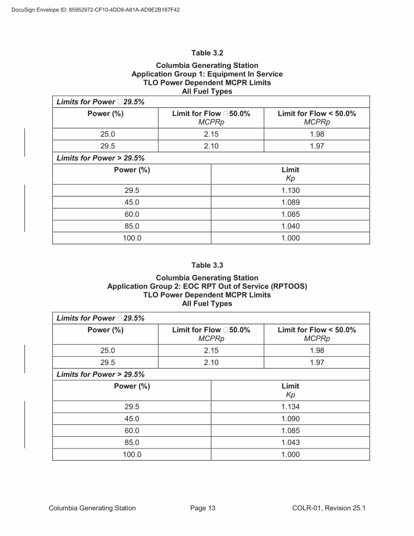
Table 3.2
Columbia Generating Station Application Group 1: Equipment In Service
TLO Power Dependent MCPR Limits All Fuel Types
Limits for Power ≤ 29.5%
Power (%) Limit for Flow ≥ 50.0% MCPRp
Limit for Flow < 50.0% MCPRp
25.0 2.15 1.98
29.5 2.10 1.97
Limits for Power > 29.5%
Power (%) Limit Kp
29.5 1.130
45.0 1.089
60.0 1.085
85.0 1.040
100.0 1.000
Table 3.3
Columbia Generating Station Application Group 2: EOC RPT Out of Service (RPTOOS)
TLO Power Dependent MCPR Limits All Fuel Types
Limits for Power ≤ 29.5%
Power (%) Limit for Flow ≥ 50.0% MCPRp
Limit for Flow < 50.0% MCPRp
25.0 2.15 1.98
29.5 2.10 1.97
Limits for Power > 29.5%
Power (%) Limit Kp
29.5 1.134
45.0 1.090
60.0 1.085
85.0 1.043
100.0 1.000
Columbia Generating Station Page 14 COLR-01, Revision 25.1
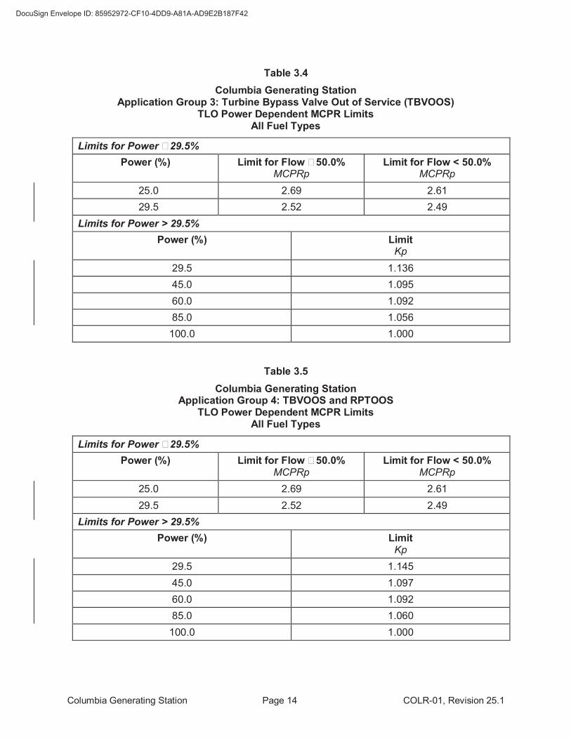
Table 3.4
Columbia Generating Station Application Group 3: Turbine Bypass Valve Out of Service (TBVOOS)
TLO Power Dependent MCPR Limits All Fuel Types
Limits for Power ≤ 29.5%
Power (%) Limit for Flow ≥ 50.0% MCPRp
Limit for Flow < 50.0% MCPRp
25.0 2.69 2.61
29.5 2.52 2.49
Limits for Power > 29.5%
Power (%) Limit Kp
29.5 1.136
45.0 1.095
60.0 1.092
85.0 1.056
100.0 1.000
Table 3.5
Columbia Generating Station Application Group 4: TBVOOS and RPTOOS
TLO Power Dependent MCPR Limits All Fuel Types
Limits for Power ≤ 29.5%
Power (%) Limit for Flow ≥ 50.0% MCPRp
Limit for Flow < 50.0% MCPRp
25.0 2.69 2.61
29.5 2.52 2.49
Limits for Power > 29.5%
Power (%) Limit Kp
29.5 1.145
45.0 1.097
60.0 1.092
85.0 1.060
100.0 1.000
Columbia Generating Station Page 15 COLR-01, Revision 25.1
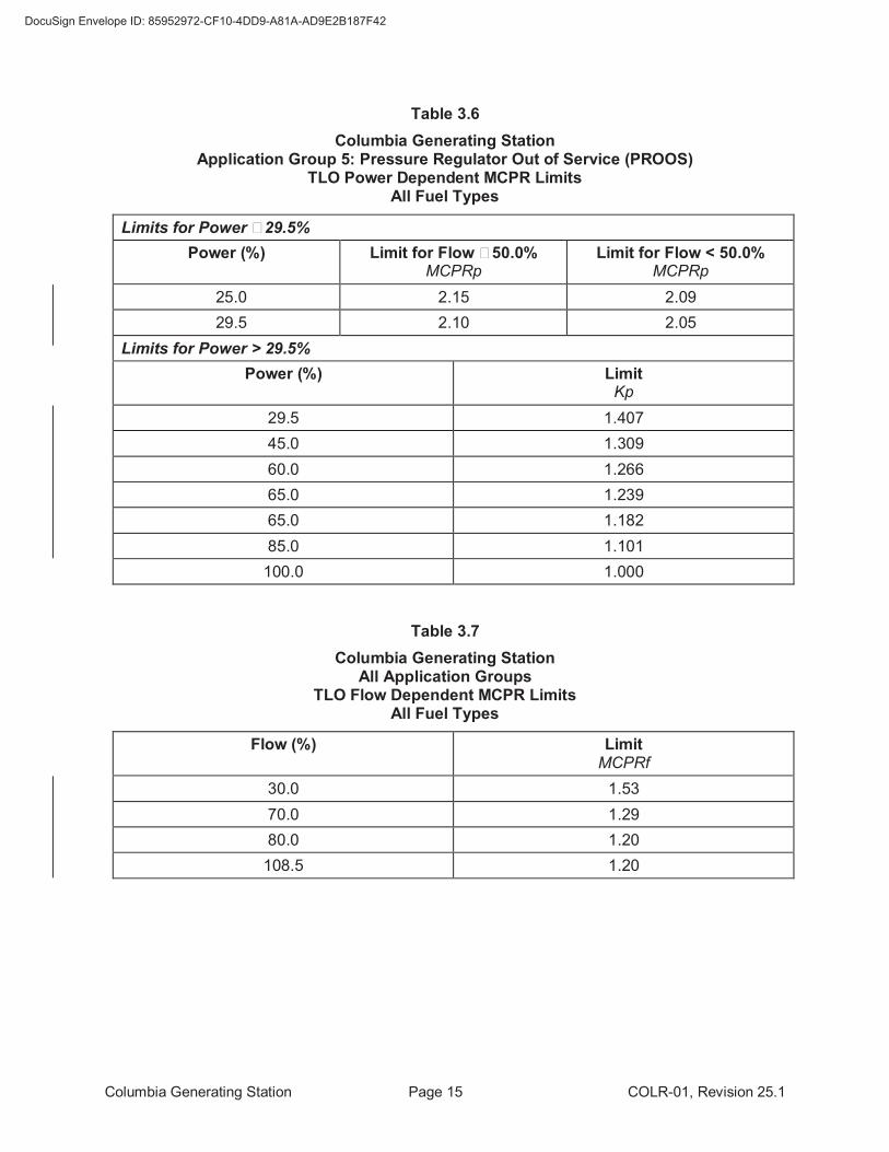
Table 3.6
Columbia Generating Station Application Group 5: Pressure Regulator Out of Service (PROOS)
TLO Power Dependent MCPR Limits All Fuel Types
Limits for Power ≤ 29.5%
Power (%) Limit for Flow ≥ 50.0% MCPRp
Limit for Flow < 50.0% MCPRp
25.0 2.15 2.09
29.5 2.10 2.05
Limits for Power > 29.5%
Power (%) Limit Kp
29.5 1.407
45.0 1.309
60.0 1.266
65.0 1.239
65.0 1.182
85.0 1.101
100.0 1.000
Table 3.7
Columbia Generating Station All Application Groups
TLO Flow Dependent MCPR Limits All Fuel Types
Flow (%) Limit MCPRf
30.0 1.53
70.0 1.29
80.0 1.20
108.5 1.20
Columbia Generating Station Page 16 COLR-01, Revision 25.1
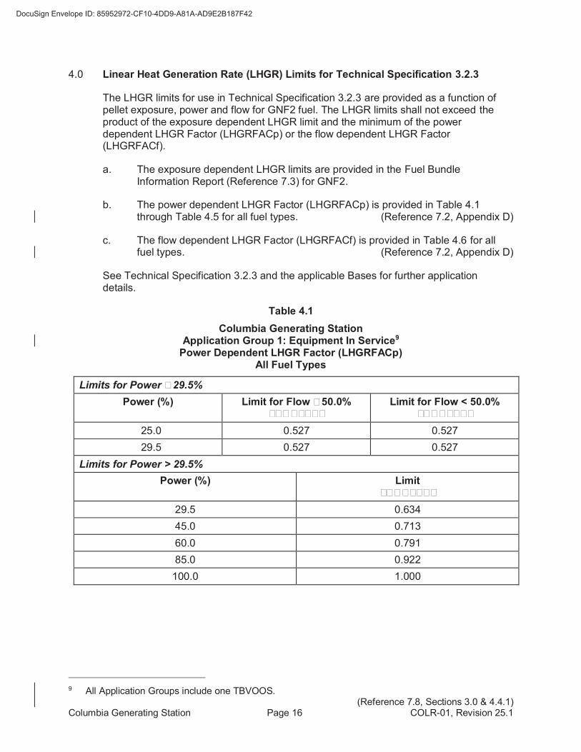
4.0 Linear Heat Generation Rate (LHGR) Limits for Technical Specification 3.2.3
The LHGR limits for use in Technical Specification 3.2.3 are provided as a function of pellet exposure, power and flow for GNF2 fuel. The LHGR limits shall not exceed the product of the exposure dependent LHGR limit and the minimum of the power dependent LHGR Factor (LHGRFACp) or the flow dependent LHGR Factor (LHGRFACf).
a. The exposure dependent LHGR limits are provided in the Fuel Bundle Information Report (Reference 7.3) for GNF2.
b. The power dependent LHGR Factor (LHGRFACp) is provided in Table 4.1 through Table 4.5 for all fuel types. (Reference 7.2, Appendix D)
c. The flow dependent LHGR Factor (LHGRFACf) is provided in Table 4.6 for all fuel types. (Reference 7.2, Appendix D)
See Technical Specification 3.2.3 and the applicable Bases for further application details.
Table 4.1
Columbia Generating Station Application Group 1: Equipment In Service9
Power Dependent LHGR Factor (LHGRFACp) All Fuel Types
Limits for Power ≤ 29.5%
Power (%) Limit for Flow ≥ 50.0% LHGRFACp
Limit for Flow < 50.0% LHGRFACp
25.0 0.527 0.527
29.5 0.527 0.527
Limits for Power > 29.5%
Power (%) Limit LHGRFACp
29.5 0.634
45.0 0.713
60.0 0.791
85.0 0.922
100.0 1.000
9 All Application Groups include one TBVOOS.
(Reference 7.8, Sections 3.0 & 4.4.1)
Columbia Generating Station Page 17 COLR-01, Revision 25.1
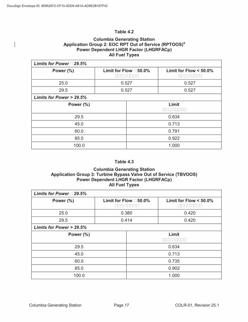
Table 4.2
Columbia Generating Station Application Group 2: EOC RPT Out of Service (RPTOOS)9
Power Dependent LHGR Factor (LHGRFACp) All Fuel Types
Limits for Power ≤ 29.5%
Power (%) Limit for Flow ≥ 50.0% LHGRFACp
Limit for Flow < 50.0% LHGRFACp
25.0 0.527 0.527
29.5 0.527 0.527
Limits for Power > 29.5%
Power (%) Limit LHGRFACp
29.5 0.634
45.0 0.713
60.0 0.791
85.0 0.922
100.0 1.000
Table 4.3
Columbia Generating Station Application Group 3: Turbine Bypass Valve Out of Service (TBVOOS)
Power Dependent LHGR Factor (LHGRFACp) All Fuel Types
Limits for Power ≤ 29.5%
Power (%) Limit for Flow ≥ 50.0% LHGRFACp
Limit for Flow < 50.0% LHGRFACp
25.0 0.380 0.420
29.5 0.414 0.420
Limits for Power > 29.5%
Power (%) Limit LHGRFACp
29.5 0.634
45.0 0.713
60.0 0.735
85.0 0.902
100.0 1.000
Columbia Generating Station Page 18 COLR-01, Revision 25.1
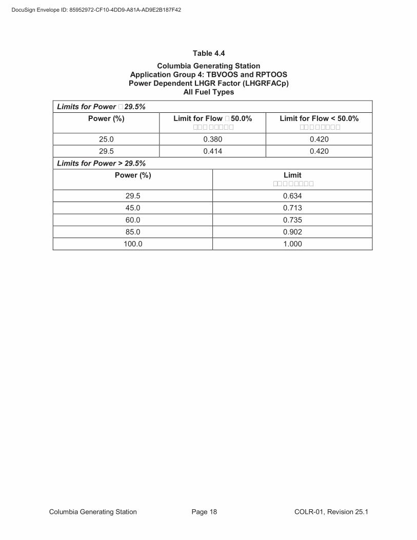
Table 4.4
Columbia Generating Station Application Group 4: TBVOOS and RPTOOS Power Dependent LHGR Factor (LHGRFACp)
All Fuel Types
Limits for Power ≤ 29.5%
Power (%) Limit for Flow ≥ 50.0% LHGRFACp
Limit for Flow < 50.0% LHGRFACp
25.0 0.380 0.420
29.5 0.414 0.420
Limits for Power > 29.5%
Power (%) Limit LHGRFACp
29.5 0.634
45.0 0.713
60.0 0.735
85.0 0.902
100.0 1.000
Columbia Generating Station Page 19 COLR-01, Revision 25.1
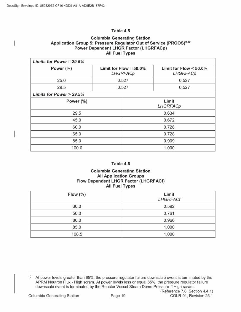
Table 4.5
Columbia Generating Station Application Group 5: Pressure Regulator Out of Service (PROOS)9,10
Power Dependent LHGR Factor (LHGRFACp) All Fuel Types
Limits for Power ≤ 29.5%
Power (%) Limit for Flow ≥ 50.0% LHGRFACp
Limit for Flow < 50.0% LHGRFACp
25.0 0.527 0.527
29.5 0.527 0.527
Limits for Power > 29.5%
Power (%) Limit LHGRFACp
29.5 0.634
45.0 0.672
60.0 0.728
65.0 0.728
85.0 0.909
100.0 1.000
Table 4.6
Columbia Generating Station All Application Groups
Flow Dependent LHGR Factor (LHGRFACf) All Fuel Types
Flow (%) Limit LHGRFACf
30.0 0.592
50.0 0.761
80.0 0.966
85.0 1.000
108.5 1.000
10 At power levels greater than 65%, the pressure regulator failure downscale event is terminated by the
APRM Neutron Flux - High scram. At power levels less or equal 65%, the pressure regulator failure downscale event is terminated by the Reactor Vessel Steam Dome Pressure – High scram. (Reference 7.8, Section 4.4.1)
Columbia Generating Station Page 20 COLR-01, Revision 25.1
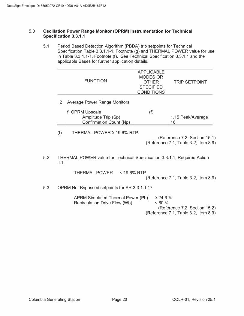
5.0 Oscillation Power Range Monitor (OPRM) Instrumentation for Technical Specification 3.3.1.1
5.1 Period Based Detection Algorithm (PBDA) trip setpoints for Technical Specification Table 3.3.1.1-1, Footnote (g) and THERMAL POWER value for use in Table 3.3.1.1-1, Footnote (f). See Technical Specification 3.3.1.1 and the applicable Bases for further application details.
FUNCTION
APPLICABLE MODES OR
OTHER SPECIFIED
CONDITIONS
TRIP SETPOINT
2 Average Power Range Monitors
f. OPRM Upscale (f) Amplitude Trip (Sp) 1.15 Peak/Average Confirmation Count (Np) 16
(f) THERMAL POWER ≥ 19.6% RTP. (Reference 7.2, Section 15.1) (Reference 7.1, Table 3-2, Item 8.9)
5.2 THERMAL POWER value for Technical Specification 3.3.1.1, Required Action J.1:
THERMAL POWER < 19.6% RTP
(Reference 7.1, Table 3-2, Item 8.9)
5.3 OPRM Not Bypassed setpoints for SR 3.3.1.1.17
APRM Simulated Thermal Power (Pb) ≥ 24.6 % Recirculation Drive Flow (Wb) < 60 %
(Reference 7.2, Section 15.2) (Reference 7.1, Table 3-2, Item 8.9)
Columbia Generating Station Page 21 COLR-01, Revision 25.1
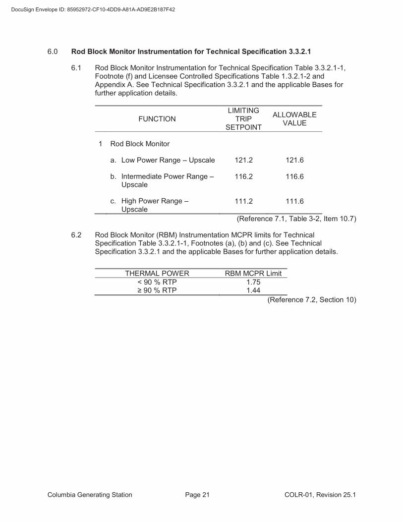
6.0 Rod Block Monitor Instrumentation for Technical Specification 3.3.2.1
6.1 Rod Block Monitor Instrumentation for Technical Specification Table 3.3.2.1-1, Footnote (f) and Licensee Controlled Specifications Table 1.3.2.1-2 and Appendix A. See Technical Specification 3.3.2.1 and the applicable Bases for further application details.
FUNCTION LIMITING
TRIP SETPOINT
ALLOWABLE VALUE
1 Rod Block Monitor
a. Low Power Range – Upscale 121.2 121.6
b. Intermediate Power Range – Upscale
116.2 116.6
c. High Power Range – Upscale
111.2 111.6
(Reference 7.1, Table 3-2, Item 10.7)
6.2 Rod Block Monitor (RBM) Instrumentation MCPR limits for Technical Specification Table 3.3.2.1-1, Footnotes (a), (b) and (c). See Technical Specification 3.3.2.1 and the applicable Bases for further application details.
THERMAL POWER RBM MCPR Limit
< 90 % RTP 1.75 ≥ 90 % RTP 1.44
(Reference 7.2, Section 10)
Columbia Generating Station Page 22 COLR-01, Revision 25.1
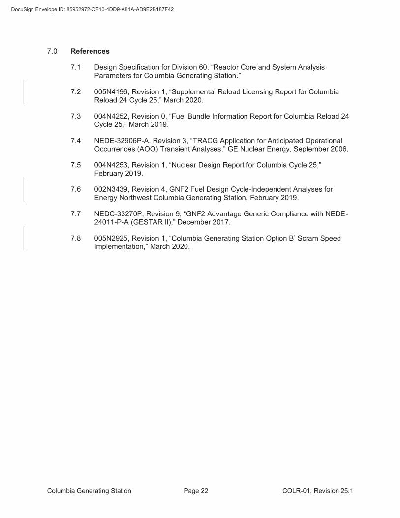
7.0 References
7.1 Design Specification for Division 60, “Reactor Core and System Analysis Parameters for Columbia Generating Station.”
7.2 005N4196, Revision 1, “Supplemental Reload Licensing Report for Columbia Reload 24 Cycle 25,” March 2020.
7.3 004N4252, Revision 0, “Fuel Bundle Information Report for Columbia Reload 24 Cycle 25,” March 2019.
7.4 NEDE-32906P-A, Revision 3, “TRACG Application for Anticipated Operational Occurrences (AOO) Transient Analyses,” GE Nuclear Energy, September 2006.
7.5 004N4253, Revision 1, “Nuclear Design Report for Columbia Cycle 25,” February 2019.
7.6 002N3439, Revision 4, GNF2 Fuel Design Cycle-Independent Analyses for Energy Northwest Columbia Generating Station, February 2019.
7.7 NEDC-33270P, Revision 9, “GNF2 Advantage Generic Compliance with NEDE-24011-P-A (GESTAR II),” December 2017.
7.8 005N2925, Revision 1, “Columbia Generating Station Option B’ Scram Speed Implementation,” March 2020.