Embed Size (px)
Citation preview
Forschungszentrum Karlsruhein der Helmholtz-Gemeinschaft
Energy Calibration and Stability ofthe ANKA Storage Ring
A.-S. Müller, I. Birkel, E. Huttel, F. PérezV, M. PontV, R. Rossmanith
Institut für Synchrotronstrahlung – ISS
Forschungszentrum Karlsruhe
V now at ALBA Synchrotron Light Source, Spain
10/12/2004 Energy Calibration of ANKA IWBS2004 – page 1/21

Overview
Brief introduction to ANKA
Why energy stability is an issue at ANKA
How to calibrate the beam energy in a very precise(but simple) wayÜ resonant depolarisationÜ makeshift polarimeter
Summary
10/12/2004 Energy Calibration of ANKA – Introduction IWBS2004 – page 2/21
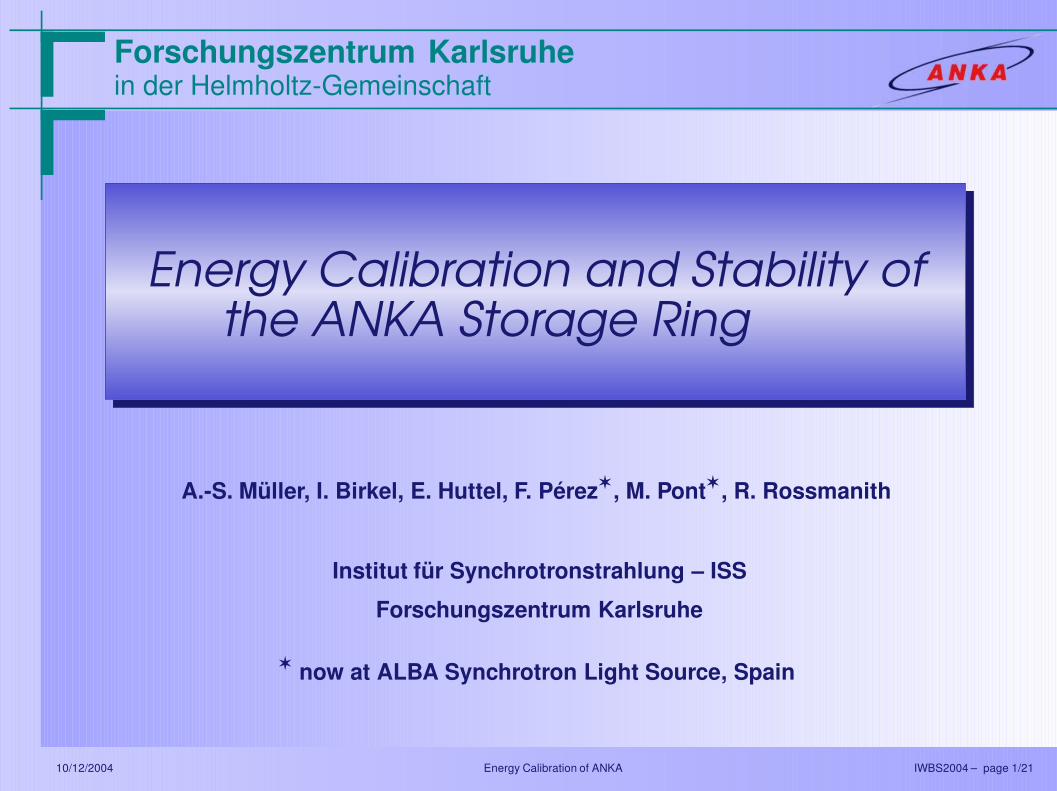
Research Centre Karlsruhe
Research & development in various fields:
environmental analysis
medicine/bio technology
material science
microsystem technology
(astro) particle physics
IT science
nano technology
...
10/12/2004 Energy Calibration of ANKA – Introduction IWBS2004 – page 3/21

ÅNgströmquelle KArlsruheTradition in the production of electromagnetic radiation in KA
1887
First observation of electromagneticwaves in Karlsruhe by Heinrich Hertz
(“Hertz Dipole”)
1996
Ground-breaking ceremony for ANKAFirst beam in 2000Regular user operation since 2001/2002
10/12/2004 Energy Calibration of ANKA – Introduction IWBS2004 – page 4/21
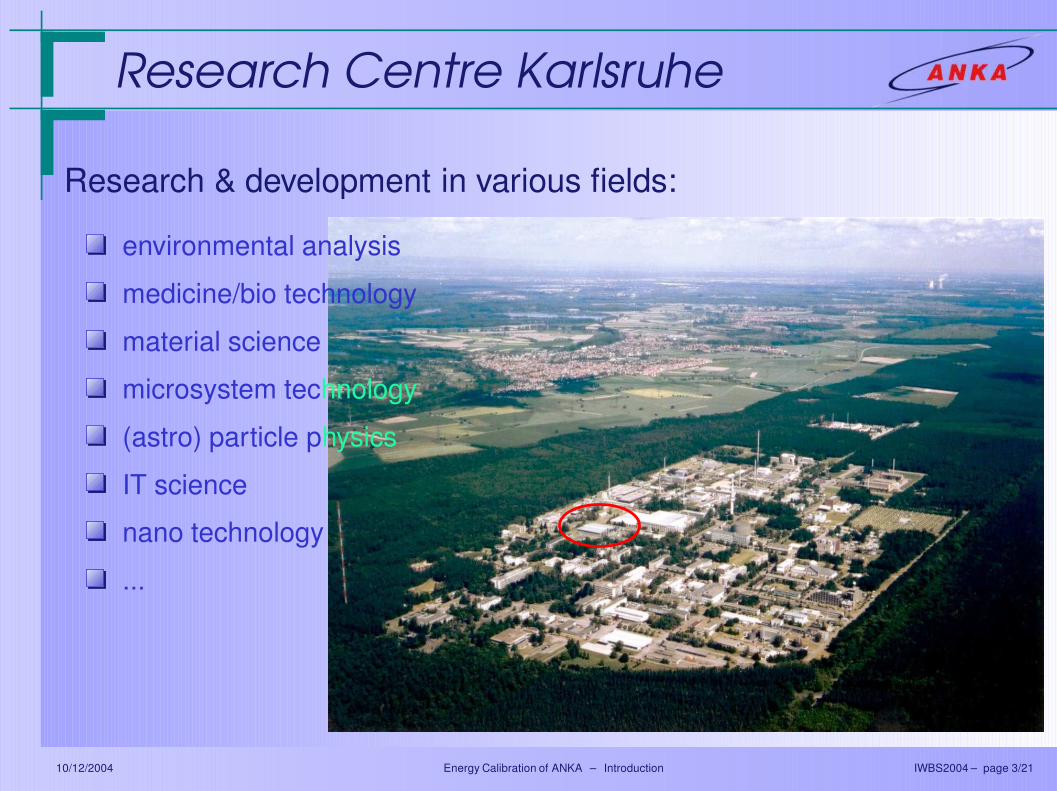
The ANKA FacilityElectron storage ring witha beam energy of 2.5 GeV
hosts 12 beamlinesÜ running: 6 + 3Ü commissioning: 3Ü planned: 1
Mostly bending magnetbeam linesÜ free space for 5 IDsÜ two installed
Development of SC IDsÜ planar SCU to come
in the near futureÜ first prototype of
helical SCU10/12/2004 Energy Calibration of ANKA – Introduction IWBS2004 – page 5/21

The ANKA Storage Ring
4 C = 110.4 m4 0.5 ≤E0 ≤2.5 GeV4 εx = 80 40 nm·rad4 coupling ≈ 1%
7
Beam position reproducibility:
8 6 weeks RMS: 15 µm8 6 weeks RMS without ramp drift: 8 µm8 1 h RMS: < 2 µm
10/12/2004 Energy Calibration of ANKA – Introduction IWBS2004 – page 6/21
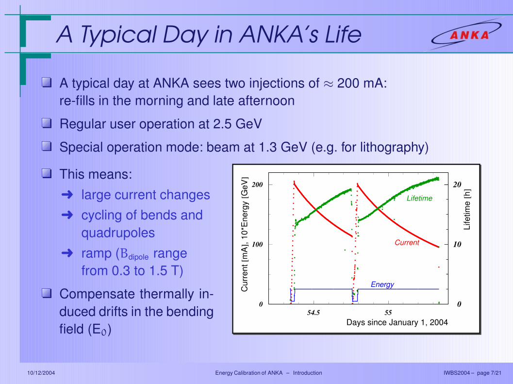
A Typical Day in ANKA’s Life
A typical day at ANKA sees two injections of ≈ 200 mA:re-fills in the morning and late afternoon
Regular user operation at 2.5 GeV
Special operation mode: beam at 1.3 GeV (e.g. for lithography)
This means:Ü large current changesÜ cycling of bends and
quadrupolesÜ ramp (Bdipole range
from 0.3 to 1.5 T)
Compensate thermally in-duced drifts in the bendingfield (E0)
Cur
rent
[mA
], 10
*Ene
rgy
[GeV
]
Life
time
[h]
Days since January 1, 2004
Lifetime
Current
Energy
0
10
20
0
100
200
54.5 55
10/12/2004 Energy Calibration of ANKA – Introduction IWBS2004 – page 7/21

Field Drift Correction
30 beam position monitors
28 horizontal correctors
16 vertical correctors
SVD based orbit correctionby cosylab
choice between measured ormodel response matrix
RF frequency as a freeparameter in the correction
∆p
p= −
1
αc
(fRF − fcRF)
fRF
10/12/2004 Energy Calibration of ANKA – Introduction IWBS2004 – page 8/21
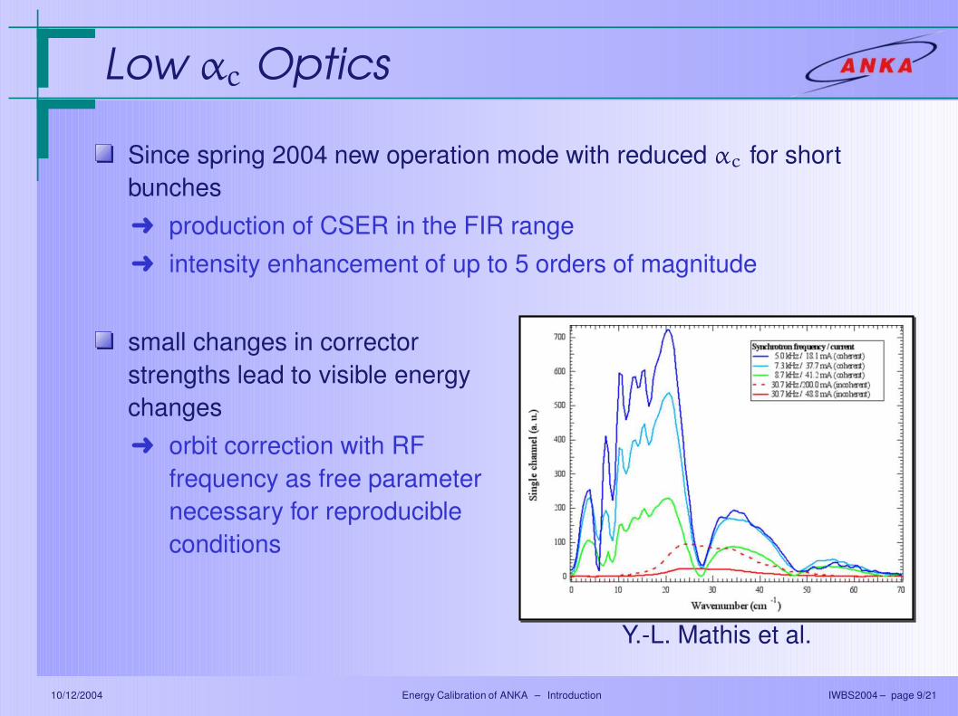
Low αc Optics
Since spring 2004 new operation mode with reduced αc for shortbunchesÜ production of CSER in the FIR rangeÜ intensity enhancement of up to 5 orders of magnitude
small changes in correctorstrengths lead to visible energychangesÜ orbit correction with RF
frequency as free parameternecessary for reproducibleconditions
Y.-L. Mathis et al.
10/12/2004 Energy Calibration of ANKA – Introduction IWBS2004 – page 9/21

External InfluenceRF frequency adjustment keeps path length constant
RF
RF∝
∝ −
daily drifts caused byinjection and rampingscheme
significant seasonaldependence
how well does this trulyreproduce the nominalbeam energy?
10/12/2004 Energy Calibration of ANKA – Introduction IWBS2004 – page 10/21
Energy Calibration
Why do we need to know the beam energy?Ü as a cross-check for the energy correction by frequency
adjustmentÜ for ID characterisation:
εγ ∝ E2 þ 1% ∆E/E Ü 2% ∆εγ/εγ
Ü for further development of optics, an excellent knowledge andunderstanding of the present optics is needed: energy errors aregradient errors!
Measure E0 with highest possible precision: Resonant Depolarisation
10/12/2004 Energy Calibration of ANKA – The Principle IWBS2004 – page 11/21
Transverse Polarisation
Polarisation build-up by emission of synchrotron radiation:
Ü asymmetry in spin flip probability leads to transverse polarisationÜ max. polarisation is given by size of asymmetry term:
8/5√
3 ≈ 92.4%
Polarisation level increases exponentially with build up time
τp =8
5√
3
m60 c10 ρ3
h rc E50
Ü for ANKA at 2.5 GeV: τp ≈ 10 minutes
10/12/2004 Energy Calibration of ANKA – The Principle IWBS2004 – page 12/21
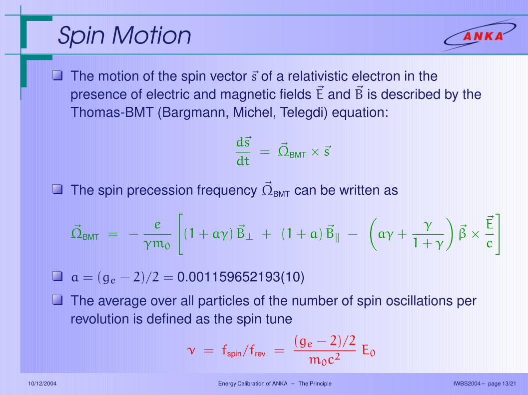
Spin Motion
The motion of the spin vector ~s of a relativistic electron in thepresence of electric and magnetic fields ~E and ~B is described by theThomas-BMT (Bargmann, Michel, Telegdi) equation:
d~s
dt= ~ΩBMT × ~s
The spin precession frequency ~ΩBMT can be written as
~ΩBMT = −e
γm0
[
(1 + aγ) ~B⊥ + (1 + a) ~B‖ −
(
aγ +γ
1 + γ
)
~β ×~E
c
]
a = (ge − 2)/2 = 0.001159652193(10)
The average over all particles of the number of spin oscillations perrevolution is defined as the spin tune
ν = fspin/frev =(ge − 2)/2
m0c2E0
10/12/2004 Energy Calibration of ANKA – The Principle IWBS2004 – page 13/21
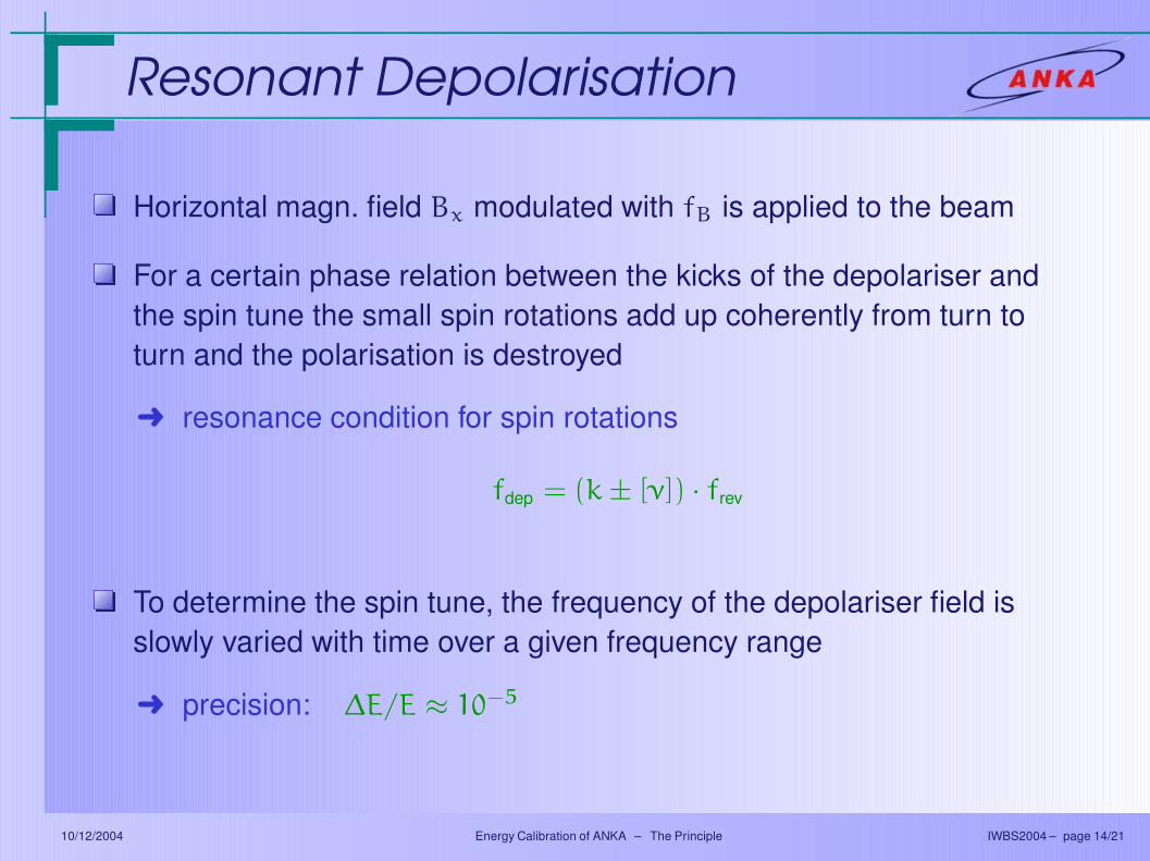
Resonant Depolarisation
Horizontal magn. field Bx modulated with fB is applied to the beam
For a certain phase relation between the kicks of the depolariser andthe spin tune the small spin rotations add up coherently from turn toturn and the polarisation is destroyed
Ü resonance condition for spin rotations
fdep = (k ± [ν]) · frev
To determine the spin tune, the frequency of the depolariser field isslowly varied with time over a given frequency range
Ü precision: ∆E/E ≈ 10−5
10/12/2004 Energy Calibration of ANKA – The Principle IWBS2004 – page 14/21
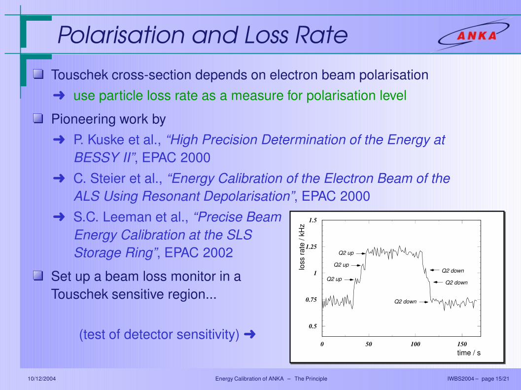
Polarisation and Loss Rate
Touschek cross-section depends on electron beam polarisationÜ use particle loss rate as a measure for polarisation level
Pioneering work byÜ P. Kuske et al., “High Precision Determination of the Energy at
BESSY II”, EPAC 2000Ü C. Steier et al., “Energy Calibration of the Electron Beam of the
ALS Using Resonant Depolarisation”, EPAC 2000Ü S.C. Leeman et al., “Precise Beam
Energy Calibration at the SLSStorage Ring”, EPAC 2002
Set up a beam loss monitor in aTouschek sensitive region...
(test of detector sensitivity) Ü
loss
rate
/ kH
z
time / s
0.5
0.75
1
1.25
1.5
0 50 100 150
Q2 up
Q2 up
Q2 up
Q2 down
Q2 down
Q2 down
10/12/2004 Energy Calibration of ANKA – The Principle IWBS2004 – page 15/21
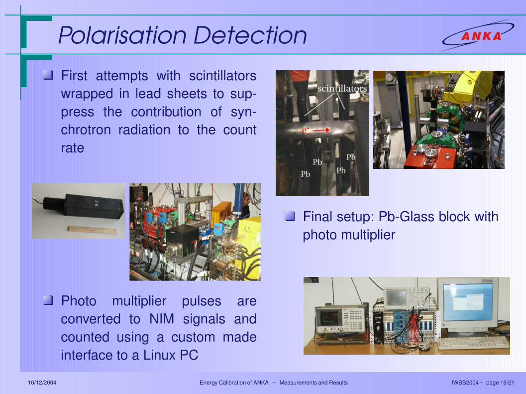
Polarisation Detection
First attempts with scintillatorswrapped in lead sheets to sup-press the contribution of syn-chrotron radiation to the countrate
Final setup: Pb-Glass block withphoto multiplier
Photo multiplier pulses areconverted to NIM signals andcounted using a custom madeinterface to a Linux PC
10/12/2004 Energy Calibration of ANKA – Measurements and Results IWBS2004 – page 16/21
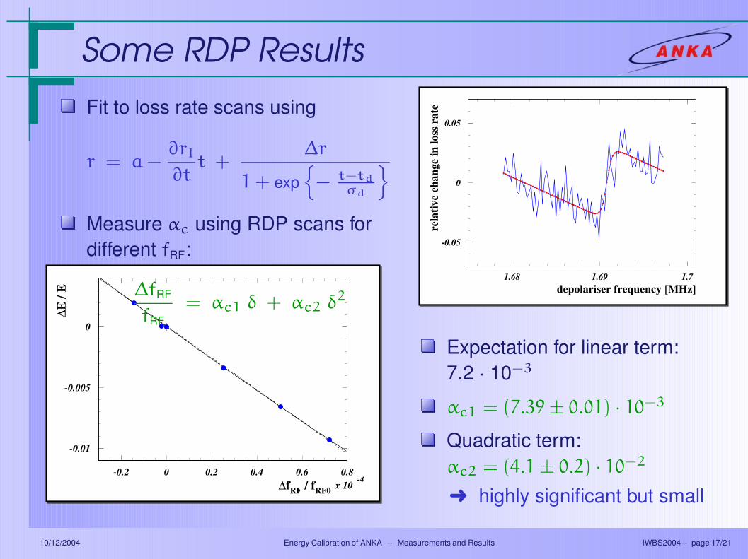
Some RDP Results∆E
/ E
∆fRF / fRF0
-0.01
-0.005
0
-0.2 0 0.2 0.4 0.6 0.8x 10
-4
Fit to loss rate scans using
r = a −∂rI
∂tt +
∆r
1 + exp
− t−td
σd
Measure αc using RDP scans fordifferent fRF:
∆fRF
fRF= αc1 δ + αc2 δ2
Expectation for linear term:7.2 · 10−3
αc1 = (7.39 ± 0.01) · 10−3
Quadratic term:αc2 = (4.1 ± 0.2) · 10−2
Ü highly significant but small
rela
tive
chan
ge in
loss
rat
e
depolariser frequency [MHz]
-0.05
0
0.05
1.68 1.69 1.7
10/12/2004 Energy Calibration of ANKA – Measurements and Results IWBS2004 – page 17/21
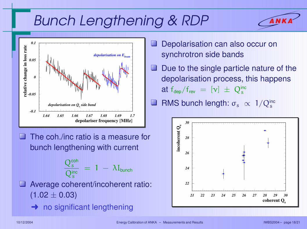
Bunch Lengthening & RDPre
lativ
e ch
ange
in lo
ss r
ate
depolariser frequency [MHz]
depolarisation on Ebeam
depolarisation on Qs side band
-0.1
-0.05
0
0.05
0.1
1.64 1.65 1.66 1.67 1.68 1.69 1.7
inco
here
nt Q
s
coherent Qs
22
24
26
28
30
21 22 23 24 25 26 27 28 29 30
Depolarisation can also occur onsynchrotron side bands
Due to the single particle nature of thedepolarisation process, this happensat fdep/frev = [ν] ± Qinc
s
RMS bunch length: σs ∝ 1/Qincs
The coh./inc ratio is a measure forbunch lengthening with current
Qcohs
Qincs
= 1 − λIbunch
Average coherent/incoherent ratio:(1.02 ± 0.03)Ü no significant lengthening
10/12/2004 Energy Calibration of ANKA – Measurements and Results IWBS2004 – page 18/21
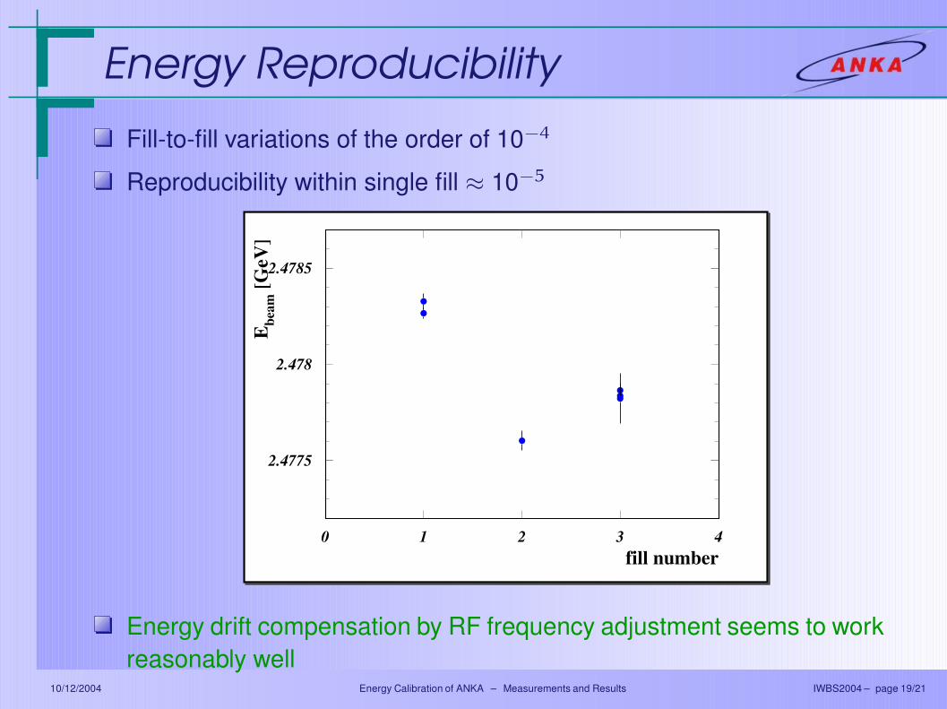
Energy Reproducibility
Fill-to-fill variations of the order of 10−4
Reproducibility within single fill ≈ 10−5
Ebe
am [G
eV]
fill number
2.4775
2.478
2.4785
0 1 2 3 4
Energy drift compensation by RF frequency adjustment seems to workreasonably well
10/12/2004 Energy Calibration of ANKA – Measurements and Results IWBS2004 – page 19/21
Summary
The beam energy is an important parameterfor accelerator and insertion devices
Very precise measurement possible withresonant depolarisation
Detection of polarisation change withTouschek-loss-polarimeter
Energy stability acceptable:
(10
)
4
4
4
4
10/12/2004 Energy Calibration of ANKA – Summary IWBS2004 – page 20/21