Embed Size (px)
Citation preview
Energy 2500 G Vers. 022
GB
1
USE AND MAINTENANCE MANUAL AND INSTRUCTIONS FOR INSTALLATION
GB
ENERGY 2500 GAS
v. 022 December 2008
GENERATORS
Energy 2500 G Vers. 022
GB
2
1
Via E. Majorana , 49 48022 Lugo (RA) ITALY
"CE" COMPLIANCE STATEMENT
Under Machine Directive 89/392/EEC, attachment II A We hereby represent that the generating set - the data concerning which are specified below - has been designed and built to correspond to the essential safety and health requirements laid down by the European Directive on Machine Safety. This statement shall no longer be valid if any changes are introduced in the machine without our written approval. Machine: GENERATOR-SET Model: ENERGY 2500 G Serial number: ………………………... Reference Directive: Machine Directive (89/392/EEC) version 91/31/EEC Low Voltage Directive (73/23/EEC) Electro-magnetic Compatibility (89/336/EEC) version 93/31/EEC Harmonised standards applied, in particular: EN 292-1; EN 292-2; EN 60204-1 DATE ........18/12/2008.......... THE PRESIDENT
Vers. 022 Energy 2500 G
GB
3
INDEX 1 FOREWORD ..................................................................................................................................... 4
1.1 Purpose and scope of this manual ............................................................................................. 4 1.2 Symbols and Definitions ............................................................................................................. 4 1.3 General Information .................................................................................................................... 4
2 GENERATING SET IDENTIFICATION DATA .................................................................................. 5 2.1 Components (Fig. 1) ................................................................................................................... 5 2.2 Identification plate (Fig. 2) .......................................................................................................... 5 2.3 Overall dimensions ..................................................................................................................... 5 2.4 Technical specifications.............................................................................................................. 6
3 SHIPPING, HANDLING, STORAGE................................................................................................. 6 3.1 Storage ....................................................................................................................................... 6 3.2 Weight......................................................................................................................................... 6 3.3 Handling...................................................................................................................................... 7
4 INSTALLATION ................................................................................................................................ 7 4.1 Preliminary information ............................................................................................................... 7 4.2 Instructions for fastening the generating set ............................................................................... 7 4.3 FASTENING the pressure reducer ............................................................................................. 8 4.4 Wiring connection instructions .................................................................................................... 9 4.5 Battery connection ...................................................................................................................... 9 4.6 Electric Load connection............................................................................................................. 9 4.7 Auxiliary electric cable connection............................................................................................ 10
4.7.1 Electric System fuses......................................................................................................... 10 4.8 Electronic control panel connection .......................................................................................... 11 4.9 Battery charger ......................................................................................................................... 11
4.9.1 Auxiliary Battery Charger ................................................................................................... 11 4.10 Connecting an additional silencer........................................................................................... 12 4.11 Connecting an External Network Relay .................................................................................. 13
5 OPERATING INSTRUCTIONS ....................................................................................................... 14 5.1 Machine safety.......................................................................................................................... 14
6 USING THE GENERATING SET .................................................................................................... 15 6.1 Starting up the generating set................................................................................................... 15 6.2 Turning the generating sets off ................................................................................................. 15 6.3 Information on not recommended uses .................................................................................... 15 6.4 Useful tips ................................................................................................................................. 16 6.5 Control and alarm functions (Fig. 24) ....................................................................................... 16 6.6 Control panel alarm causes and resetting ................................................................................ 16
7 MAINTENANCE INSTRUCTIONS .................................................................................................. 17 7.1 Service check list ...................................................................................................................... 17 7.2 Maintenance not requiring specialised personnel..................................................................... 17 7.3 Checking the engine oil level .................................................................................................... 17 7.4 Maintenance operations to be carried out by qualified personnel............................................. 17
7.4.1 Engine oil replacement ...................................................................................................... 17 7.4.2 Air filter maintenance ......................................................................................................... 18 7.4.3 Spark plug maintenance .................................................................................................... 19 7.4.4 Voltage adjustment ............................................................................................................ 19
8 ROUTINE MAINTENANCE SCHEDULE ........................................................................................ 20 9 DISMANTLING................................................................................................................................ 20 10 RECOMMENDED FIRE-FIGHTING EQUIPMENT........................................................................ 20 GENERAL WARRANTY TERMS......................................................................................................... 21 WIRING DIAGRAM ENERGY 2500 G ................................................................................................. 22 DRAWING FOR SPARE PARTS LIST ENERGY 2500 G ................................................................... 24
Energy 2500 G Vers. 022
GB
4
1 FOREWORD
Refer carefully to this manual before performing any operation on the power generator set. 1.1 Purpose and scope of this manual This manual has been drawn up by the Manufacturer in order to provide basic information and instructions for performing every operation for servicing and using the generating set in a proper and safe manner. It is an integral part of the generating set equipment, must be kept with care throughout the life of the same, and must be protected against any agent which could damage it. It must follow the generating set if this is installed on a new vehicle, or if its ownership changes hands. The information in this manual is addressed to the personnel in charge of installing the generating set, and to all those involved in its maintenance and use. This manual sets out the purpose the machine was designed for, and contains all the information required to guarantee that it is used in a safe and proper manner. Constant compliance with the instructions laid down here will guarantee the safety of the user, operating economy and longer life of the machine. To facilitate reference, this manual has been subdivided into chapters specifying the main notions contained therein; for quick consultation, refer to the table of contents. The most important parts of the text are in bold letters and preceded by symbols described here below. It is strongly recommended that you read the contents of this manual and the reference documents carefully; doing so is essential to the correct long-term performance and reliability of the generator set and the prevention of injury and/or damage. Note: The information contained in this publication was correct at the time it went to print, but may be modified without advance notice.
1.2 Symbols and Definitions "Graphic safety symbols” have been employed in this booklet to identify different levels of danger or important information.
This means that you must pay attention to avoid serious consequences which might lead to serious accidents or damage the health of the operators.
This means a potentially hazardous situation which could lead to accidents or damage to property.
This calls the user’s attention to a potentially dangerous situation which could cause malfunction or damage the machine. The drawings are only provided by way of example. Even though the machine you actually have may differ from the illustrations contained in this manual, safety and information about the same are guaranteed. The manufacturer, as part of his policy of constant product development and updating, may introduce changes without giving any notice. 1.3 General Information The ENERGY generating set has been designed for installation on vehicles. It can deliver power at a voltage of 230 VAC 50 Hz. The ENERGY 2500 G model must be fed with LPG. In order to achieve a low noise level, the ENERGY series generating sets are provided with internally insulated sound-proofing cases. They can be accessed easily in order to perform maintenance work, and are provided with a remote control panel which can be installed inside the vehicle. The generating sets can be connected to the tank of the vehicle as long as the fuel type is compatible. Otherwise, install a special tank which can be supplied as an option.
Vers. 022 Energy 2500 G
GB
5
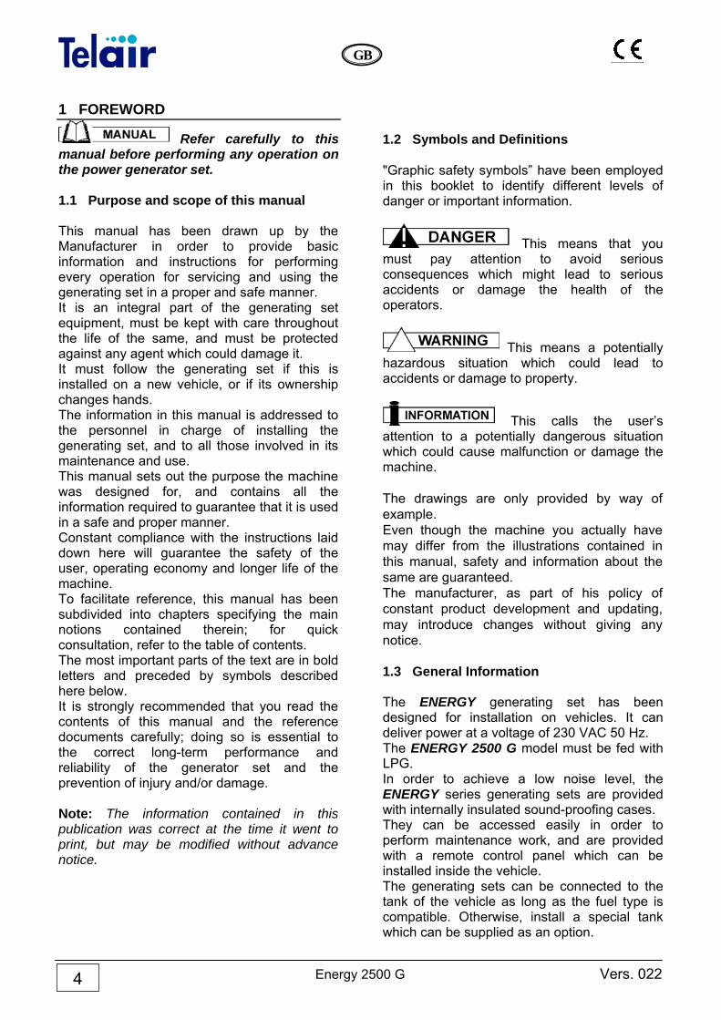
2 GENERATING SET IDENTIFICATION DATA 2.1 Components (Fig. 1) 1 Sound-proofing casing 2 Supporting brackets 3 Access door 4 Access door closure 5 Technical features sticker 6 Anti-vibration support 7 Anchoring bracket 8 Electronic control panel 9 Gas pipe and cable outlet block 10 Sliding surface locking screw 11 Supply gas arrival pipe 12 Sliding surface all out locking screw
2.2 Identification plate (Fig. 2) 1 Generating set model 2 Model code number 3 Serial number 4 Date of manufacture 5 Power factor 6 Frequency 7 Maximum electric power
8 Maximum current 9 Rated voltage 230V AC 10 Current delivered at 12V/DC 11 Weight 12 Bar code
2.3 Overall dimensions Figure 3 shows the dimensions of the generating sets.
3
1
2
Energy 2500 G Vers. 022
GB
6
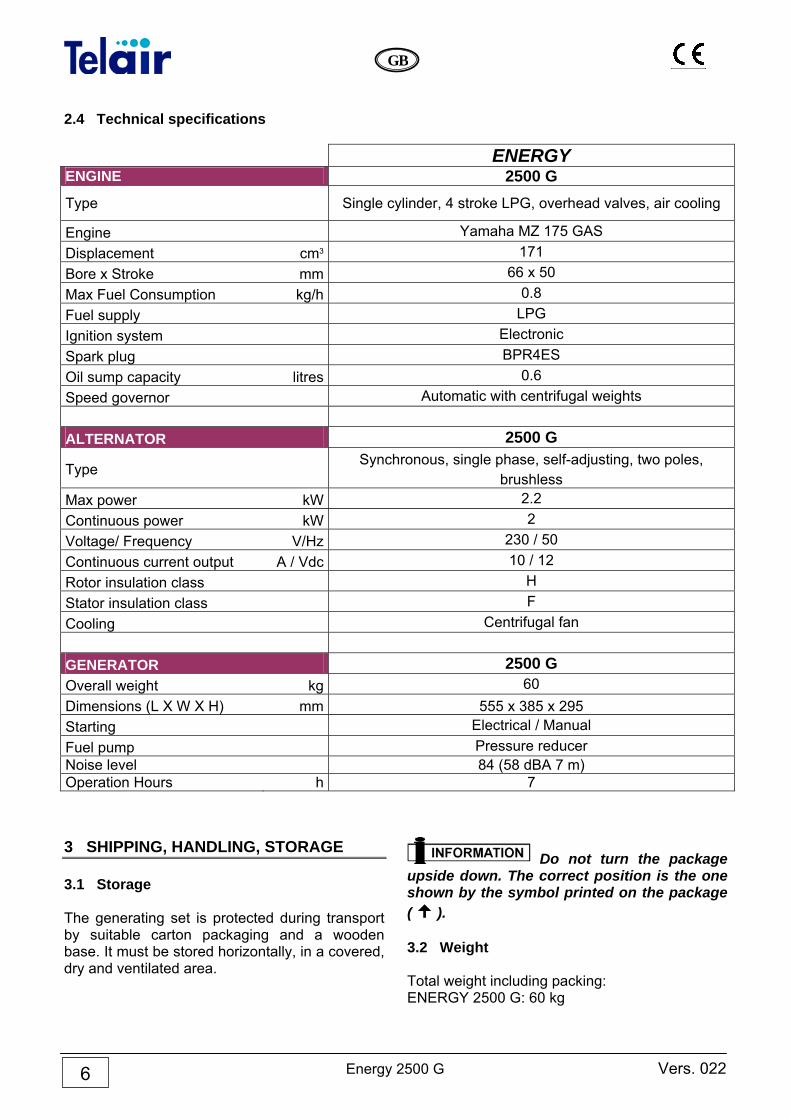
2.4 Technical specifications ENERGY ENGINE 2500 G
Type Single cylinder, 4 stroke LPG, overhead valves, air cooling
Engine Yamaha MZ 175 GAS Displacement cm3 171 Bore x Stroke mm 66 x 50 Max Fuel Consumption kg/h 0.8 Fuel supply LPG Ignition system Electronic Spark plug BPR4ES Oil sump capacity litres 0.6 Speed governor Automatic with centrifugal weights ALTERNATOR 2500 G
Type Synchronous, single phase, self-adjusting, two poles,
brushless Max power kW 2.2 Continuous power kW 2 Voltage/ Frequency V/Hz 230 / 50 Continuous current output A / Vdc 10 / 12 Rotor insulation class H Stator insulation class F Cooling Centrifugal fan GENERATOR 2500 G Overall weight kg 60 Dimensions (L X W X H) mm 555 x 385 x 295 Starting Electrical / Manual Fuel pump Pressure reducer Noise level 84 (58 dBA 7 m) Operation Hours h 7 3 SHIPPING, HANDLING, STORAGE 3.1 Storage The generating set is protected during transport by suitable carton packaging and a wooden base. It must be stored horizontally, in a covered, dry and ventilated area.
Do not turn the package upside down. The correct position is the one shown by the symbol printed on the package ( ). 3.2 Weight Total weight including packing: ENERGY 2500 G: 60 kg
Vers. 022 Energy 2500 G
GB
7
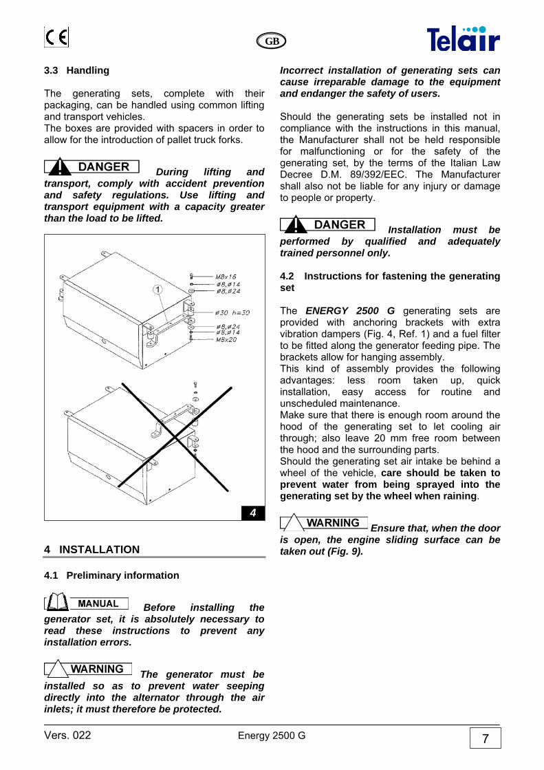
3.3 Handling The generating sets, complete with their packaging, can be handled using common lifting and transport vehicles. The boxes are provided with spacers in order to allow for the introduction of pallet truck forks.
During lifting and transport, comply with accident prevention and safety regulations. Use lifting and transport equipment with a capacity greater than the load to be lifted.
4 INSTALLATION 4.1 Preliminary information
Before installing the generator set, it is absolutely necessary to read these instructions to prevent any installation errors.
The generator must be installed so as to prevent water seeping directly into the alternator through the air inlets; it must therefore be protected.
Incorrect installation of generating sets can cause irreparable damage to the equipment and endanger the safety of users. Should the generating sets be installed not in compliance with the instructions in this manual, the Manufacturer shall not be held responsible for malfunctioning or for the safety of the generating set, by the terms of the Italian Law Decree D.M. 89/392/EEC. The Manufacturer shall also not be liable for any injury or damage to people or property.
Installation must be performed by qualified and adequately trained personnel only. 4.2 Instructions for fastening the generating set The ENERGY 2500 G generating sets are provided with anchoring brackets with extra vibration dampers (Fig. 4, Ref. 1) and a fuel filter to be fitted along the generator feeding pipe. The brackets allow for hanging assembly. This kind of assembly provides the following advantages: less room taken up, quick installation, easy access for routine and unscheduled maintenance. Make sure that there is enough room around the hood of the generating set to let cooling air through; also leave 20 mm free room between the hood and the surrounding parts. Should the generating set air intake be behind a wheel of the vehicle, care should be taken to prevent water from being sprayed into the generating set by the wheel when raining.
Ensure that, when the door is open, the engine sliding surface can be taken out (Fig. 9).
4
Energy 2500 G Vers. 022
GB
8
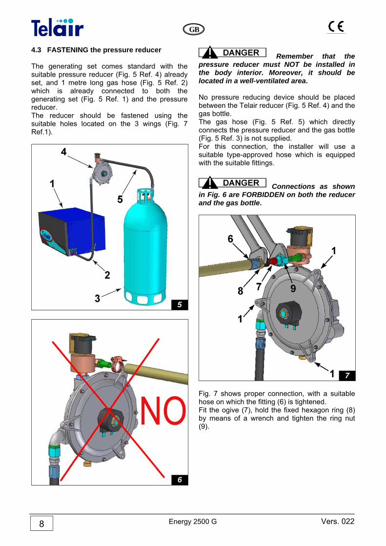
4.3 FASTENING the pressure reducer The generating set comes standard with the suitable pressure reducer (Fig. 5 Ref. 4) already set, and 1 metre long gas hose (Fig. 5 Ref. 2) which is already connected to both the generating set (Fig. 5 Ref. 1) and the pressure reducer. The reducer should be fastened using the suitable holes located on the 3 wings (Fig. 7 Ref.1).
Remember that the pressure reducer must NOT be installed in the body interior. Moreover, it should be located in a well-ventilated area. No pressure reducing device should be placed between the Telair reducer (Fig. 5 Ref. 4) and the gas bottle. The gas hose (Fig. 5 Ref. 5) which directly connects the pressure reducer and the gas bottle (Fig. 5 Ref. 3) is not supplied. For this connection, the installer will use a suitable type-approved hose which is equipped with the suitable fittings.
Connections as shown in Fig. 6 are FORBIDDEN on both the reducer and the gas bottle.
Fig. 7 shows proper connection, with a suitable hose on which the fitting (6) is tightened. Fit the ogive (7), hold the fixed hexagon ring (8) by means of a wrench and tighten the ring nut (9).
7
6
5
Vers. 022 Energy 2500 G
GB
9
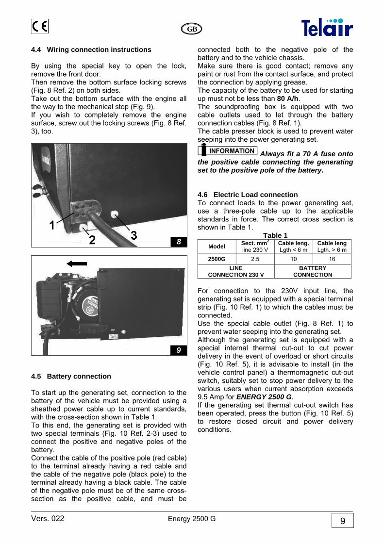
4.4 Wiring connection instructions By using the special key to open the lock, remove the front door. Then remove the bottom surface locking screws (Fig. 8 Ref. 2) on both sides. Take out the bottom surface with the engine all the way to the mechanical stop (Fig. 9). If you wish to completely remove the engine surface, screw out the locking screws (Fig. 8 Ref. 3), too.
4.5 Battery connection To start up the generating set, connection to the battery of the vehicle must be provided using a sheathed power cable up to current standards, with the cross-section shown in Table 1. To this end, the generating set is provided with two special terminals (Fig. 10 Ref. 2-3) used to connect the positive and negative poles of the battery. Connect the cable of the positive pole (red cable) to the terminal already having a red cable and the cable of the negative pole (black pole) to the terminal already having a black cable. The cable of the negative pole must be of the same cross-section as the positive cable, and must be
connected both to the negative pole of the battery and to the vehicle chassis. Make sure there is good contact; remove any paint or rust from the contact surface, and protect the connection by applying grease. The capacity of the battery to be used for starting up must not be less than 80 A/h. The soundproofing box is equipped with two cable outlets used to let through the battery connection cables (Fig. 8 Ref. 1). The cable presser block is used to prevent water seeping into the power generating set.
Always fit a 70 A fuse onto the positive cable connecting the generating set to the positive pole of the battery. 4.6 Electric Load connection To connect loads to the power generating set, use a three-pole cable up to the applicable standards in force. The correct cross section is shown in Table 1.
Table 1 Model Sect. mm2
line 230 V Cable leng. Lgth < 6 m
Cable leng Lgth. > 6 m
2500G 2.5 10 16 LINE
CONNECTION 230 V BATTERY
CONNECTION For connection to the 230V input line, the generating set is equipped with a special terminal strip (Fig. 10 Ref. 1) to which the cables must be connected. Use the special cable outlet (Fig. 8 Ref. 1) to prevent water seeping into the generating set. Although the generating set is equipped with a special internal thermal cut-out to cut power delivery in the event of overload or short circuits (Fig. 10 Ref. 5), it is advisable to install (in the vehicle control panel) a thermomagnetic cut-out switch, suitably set to stop power delivery to the various users when current absorption exceeds 9.5 Amp for ENERGY 2500 G. If the generating set thermal cut-out switch has been operated, press the button (Fig. 10 Ref. 5) to restore closed circuit and power delivery conditions.
9
8
Energy 2500 G Vers. 022
GB
10
Carefully check the position of the line connection for picking up 230 Volt current. Wrong connection could damage the generating set irreparably or create dangerous short circuits.
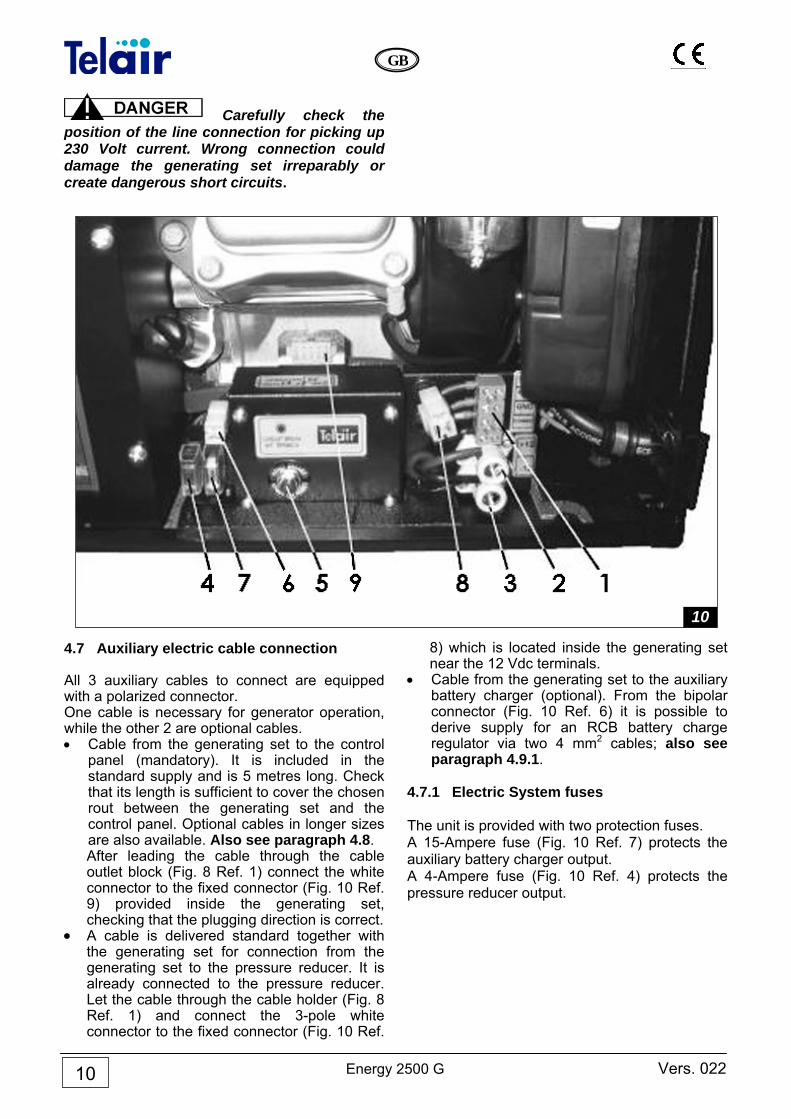
4.7 Auxiliary electric cable connection All 3 auxiliary cables to connect are equipped with a polarized connector. One cable is necessary for generator operation, while the other 2 are optional cables. • Cable from the generating set to the control
panel (mandatory). It is included in the standard supply and is 5 metres long. Check that its length is sufficient to cover the chosen rout between the generating set and the control panel. Optional cables in longer sizes are also available. Also see paragraph 4.8. After leading the cable through the cable outlet block (Fig. 8 Ref. 1) connect the white connector to the fixed connector (Fig. 10 Ref. 9) provided inside the generating set, checking that the plugging direction is correct.
• A cable is delivered standard together with the generating set for connection from the generating set to the pressure reducer. It is already connected to the pressure reducer. Let the cable through the cable holder (Fig. 8 Ref. 1) and connect the 3-pole white connector to the fixed connector (Fig. 10 Ref.
8) which is located inside the generating set near the 12 Vdc terminals.
• Cable from the generating set to the auxiliary battery charger (optional). From the bipolar connector (Fig. 10 Ref. 6) it is possible to derive supply for an RCB battery charge regulator via two 4 mm2 cables; also see paragraph 4.9.1.
4.7.1 Electric System fuses The unit is provided with two protection fuses. A 15-Ampere fuse (Fig. 10 Ref. 7) protects the auxiliary battery charger output. A 4-Ampere fuse (Fig. 10 Ref. 4) protects the pressure reducer output.
10
Vers. 022 Energy 2500 G
GB
11
4.8 Electronic control panel connection Choose your required position for the control panel inside the vehicle and drill a 30 x 32 mm rectangular hole. After letting out of the hole the connecting cable coming from the generating set (paragraph 4.7) connect the cable black connector on the back of the electronic control panel. Fix the electronic control panel (Fig. 11) by using 3 x 20 mm self-tapping screws, making sure that the rear part does not interfere with other surfaces. Apply light pressure to fix the plastic frame, until the anchoring tabs click in.
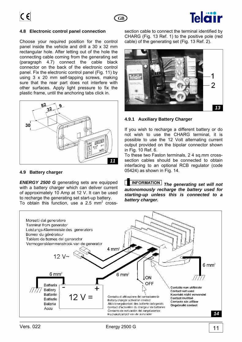
4.9 Battery charger ENERGY 2500 G generating sets are equipped with a battery charger which can deliver current of approximately 10 Amp at 12 V. It can be used to recharge the generating set start-up battery. To obtain this function, use a 2.5 mm2 cross-
section cable to connect the terminal identified by CHARG (Fig. 13 Ref. 1) to the positive pole (red cable) of the generating set (Fig. 13 Ref. 2).
4.9.1 Auxiliary Battery Charger If you wish to recharge a different battery or do not wish to use the CHARG terminal, it is possible to use the 12 Volt alternating current output provided on the bipolar connector shown in Fig. 10 Ref. 6. To these two Faston terminals, 2 4 sq.mm cross-section cables should be connected to obtain interfacing to an optional RCB regulator (code 05424) as shown in Fig. 14.
The generating set will not autonomously recharge the battery used for starting-up unless this is connected to a battery charger.
11
13
14
Energy 2500 G Vers. 022
GB
12
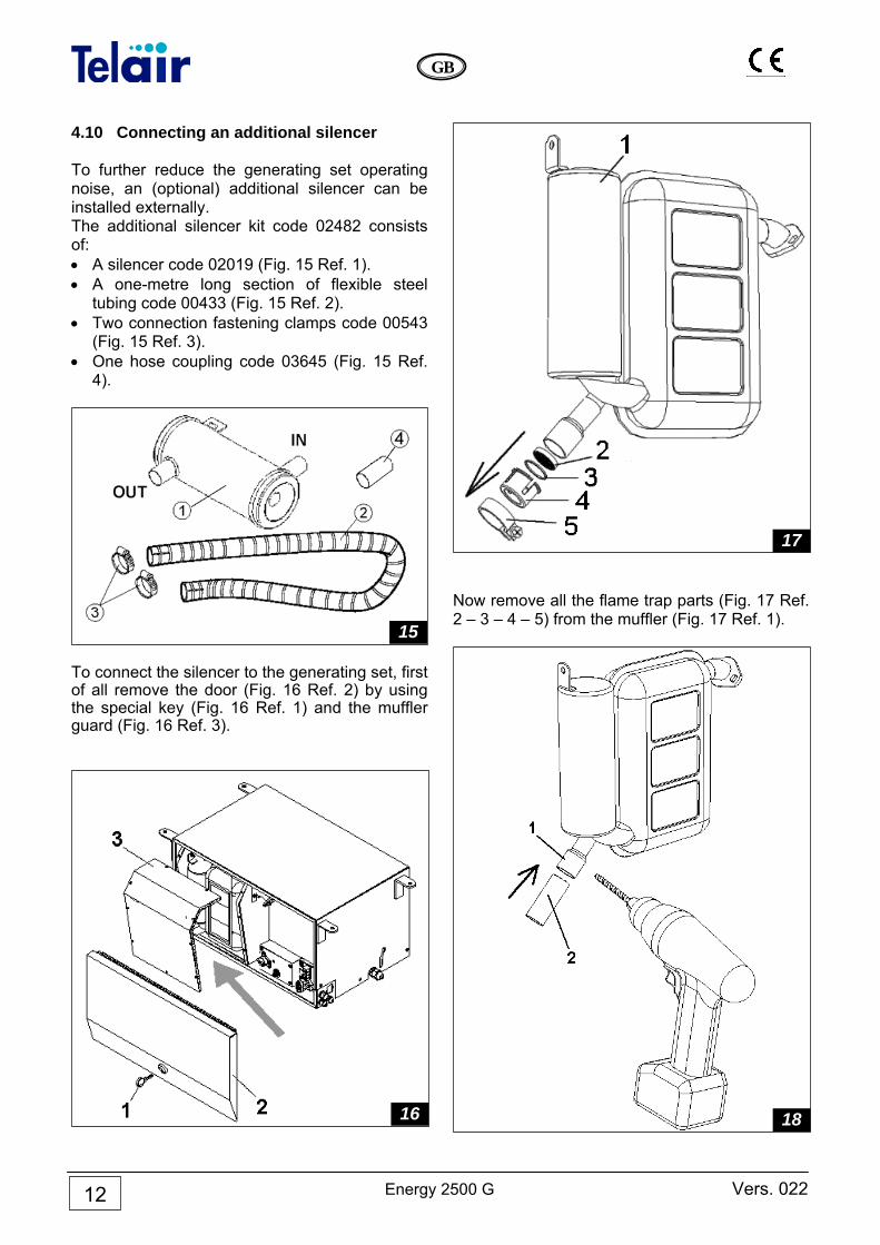
4.10 Connecting an additional silencer To further reduce the generating set operating noise, an (optional) additional silencer can be installed externally. The additional silencer kit code 02482 consists of: • A silencer code 02019 (Fig. 15 Ref. 1). • A one-metre long section of flexible steel
tubing code 00433 (Fig. 15 Ref. 2). • Two connection fastening clamps code 00543
(Fig. 15 Ref. 3). • One hose coupling code 03645 (Fig. 15 Ref.
4).
To connect the silencer to the generating set, first of all remove the door (Fig. 16 Ref. 2) by using the special key (Fig. 16 Ref. 1) and the muffler guard (Fig. 16 Ref. 3).
Now remove all the flame trap parts (Fig. 17 Ref. 2 – 3 – 4 – 5) from the muffler (Fig. 17 Ref. 1).
17
15
16 18
Vers. 022 Energy 2500 G
GB
13
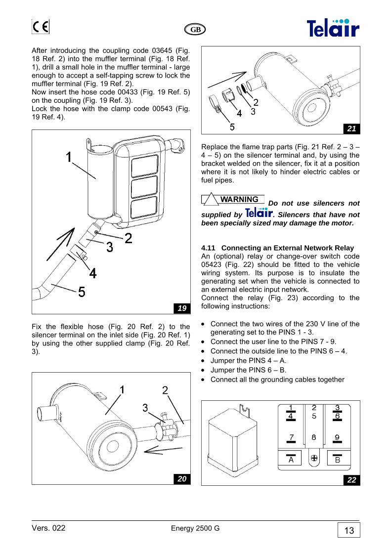
After introducing the coupling code 03645 (Fig. 18 Ref. 2) into the muffler terminal (Fig. 18 Ref. 1), drill a small hole in the muffler terminal - large enough to accept a self-tapping screw to lock the muffler terminal (Fig. 19 Ref. 2). Now insert the hose code 00433 (Fig. 19 Ref. 5) on the coupling (Fig. 19 Ref. 3). Lock the hose with the clamp code 00543 (Fig. 19 Ref. 4).
Fix the flexible hose (Fig. 20 Ref. 2) to the silencer terminal on the inlet side (Fig. 20 Ref. 1) by using the other supplied clamp (Fig. 20 Ref. 3).
Replace the flame trap parts (Fig. 21 Ref. 2 – 3 – 4 – 5) on the silencer terminal and, by using the bracket welded on the silencer, fix it at a position where it is not likely to hinder electric cables or fuel pipes.
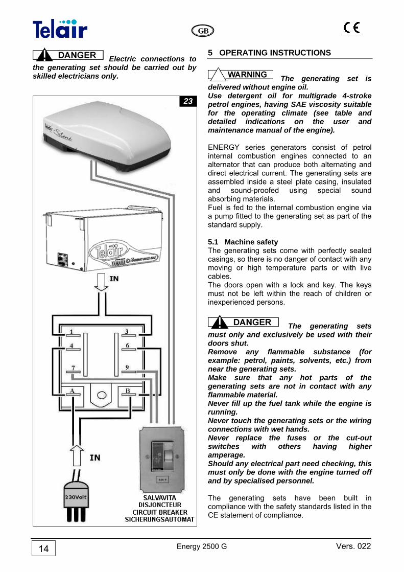
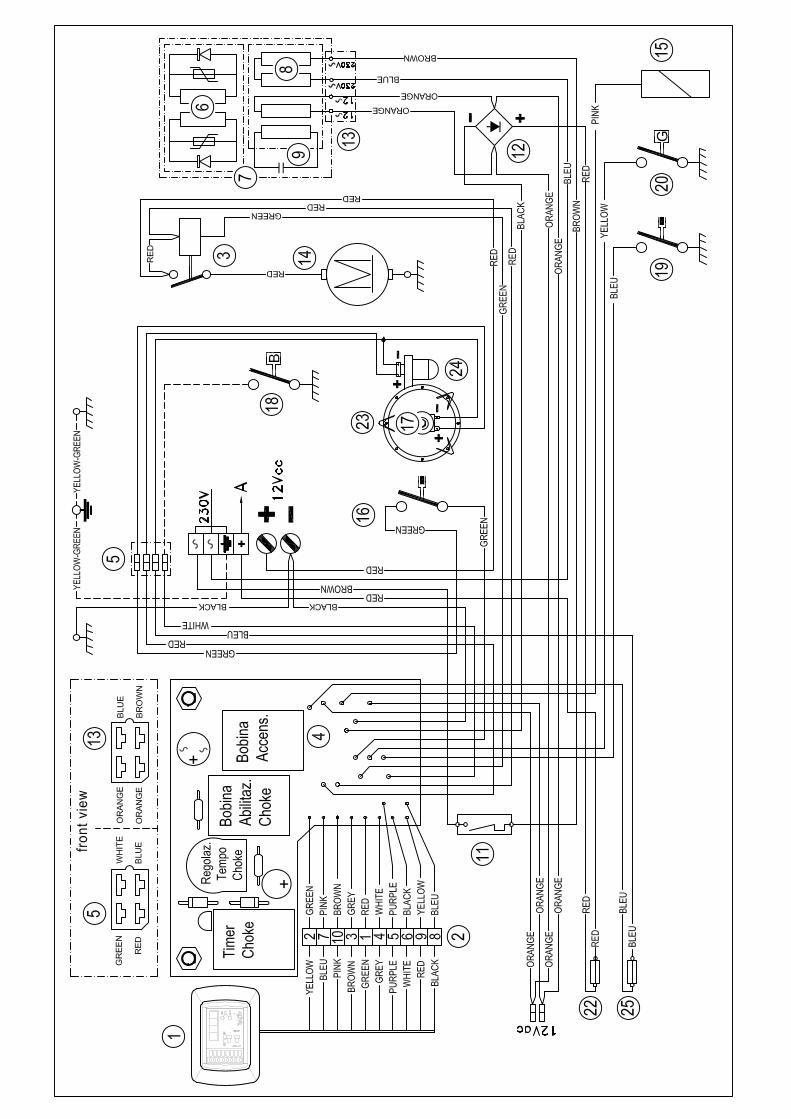
Do not use silencers not supplied by . Silencers that have not been specially sized may damage the motor. 4.11 Connecting an External Network Relay An (optional) relay or change-over switch code 05423 (Fig. 22) should be fitted to the vehicle wiring system. Its purpose is to insulate the generating set when the vehicle is connected to an external electric input network. Connect the relay (Fig. 23) according to the following instructions: • Connect the two wires of the 230 V line of the
generating set to the PINS 1 - 3. • Connect the user line to the PINS 7 - 9. • Connect the outside line to the PINS 6 – 4. • Jumper the PINS 4 – A. • Jumper the PINS 6 – B. • Connect all the grounding cables together
22
21
20
19
Energy 2500 G Vers. 022
GB
14
Electric connections to the generating set should be carried out by skilled electricians only.
5 OPERATING INSTRUCTIONS
The generating set is delivered without engine oil. Use detergent oil for multigrade 4-stroke petrol engines, having SAE viscosity suitable for the operating climate (see table and detailed indications on the user and maintenance manual of the engine). ENERGY series generators consist of petrol internal combustion engines connected to an alternator that can produce both alternating and direct electrical current. The generating sets are assembled inside a steel plate casing, insulated and sound-proofed using special sound absorbing materials. Fuel is fed to the internal combustion engine via a pump fitted to the generating set as part of the standard supply. 5.1 Machine safety The generating sets come with perfectly sealed casings, so there is no danger of contact with any moving or high temperature parts or with live cables. The doors open with a lock and key. The keys must not be left within the reach of children or inexperienced persons.
The generating sets must only and exclusively be used with their doors shut. Remove any flammable substance (for example: petrol, paints, solvents, etc.) from near the generating sets. Make sure that any hot parts of the generating sets are not in contact with any flammable material. Never fill up the fuel tank while the engine is running. Never touch the generating sets or the wiring connections with wet hands. Never replace the fuses or the cut-out switches with others having higher amperage. Should any electrical part need checking, this must only be done with the engine turned off and by specialised personnel. The generating sets have been built in compliance with the safety standards listed in the CE statement of compliance.
23
Vers. 022 Energy 2500 G
GB
15
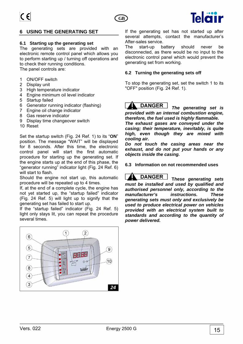
6 USING THE GENERATING SET 6.1 Starting up the generating set The generating sets are provided with an electronic remote control panel which allows you to perform starting up / turning off operations and to check their running conditions. The panel controls are: 1 ON/OFF switch 2 Display unit 3 High temperature indicator 4 Engine minimum oil level indicator 5 Startup failed 6 Generator running indicator (flashing) 7 Engine oil change indicator 8 Gas reserve indicator 9 Display time changeover switch 10 Reset Set the startup switch (Fig. 24 Ref. 1) to its “ON” position. The message “WAIT” will be displayed for 8 seconds. After this time, the electronic control panel will start the first automatic procedure for starting up the generating set. If the engine starts up at the end of this phase, the “generator running” indicator light (Fig. 24 Ref. 6) will start to flash. Should the engine not start up, this automatic procedure will be repeated up to 4 times. If, at the end of a complete cycle, the engine has not yet started up, the “startup failed” indicator (Fig. 24 Ref. 5) will light up to signify that the generating set has failed to start up. If the “startup failed” indicator (Fig. 24 Ref. 5) light only stays lit, you can repeat the procedure several times.
If the generating set has not started up after several attempts, contact the manufacturer’s After-sales service. The start-up battery should never be disconnected, as there would be no input to the electronic control panel which would prevent the generating set from working. 6.2 Turning the generating sets off To stop the generating set, set the switch 1 to its "OFF" position (Fig. 24 Ref. 1).
The generating set is provided with an internal combustion engine, therefore, the fuel used is highly flammable. The exhaust gases are conveyed under the casing; their temperature, inevitably, is quite high, even though they are mixed with cooling air. Do not touch the casing areas near the exhaust, and do not put your hands or any objects inside the casing. 6.3 Information on not recommended uses
These generating sets must be installed and used by qualified and authorised personnel only, according to the manufacturer’s instructions. These generating sets must only and exclusively be used to produce electrical power on vehicles provided with an electrical system built to standards and according to the quantity of power delivered.
24
Energy 2500 G Vers. 022
GB
16
6.4 Useful tips To make the best use of the generating sets, remember that even minor overloads - if they last long enough - will operate the thermal cut-out switches (Fig. 10 Ref. 5). During the running-in period, do not subject the new engine to loads exceeding 70% of the rated load, at least for the first 50 running hours. 6.5 Control and alarm functions (Fig. 24) 2 Display: when the generating set has started up, the total running hours will be displayed. Press the key provided below the control panel display unit (Fig. 24 Ref. 9) to display the number of generating set operation hours since the latest engine oil change. 3 High temperature indicator: this warning light will light up when the temperature of the generating set goes over its safety value; the engine will stop at the same time. 4 Engine oil minimum level indicator: this warning light will light up to indicate that oil in the engine has gone below the minimum level. A safety system will kill the engine automatically to prevent failures. 5 Engine startup failed: this warning light will light up to indicate that the generating set has not started up, after all four start-up attempts. 6 Generator running indicator: this indicator flashes during proper operation of the generating set. 7 Change oil: this warning light will light up when the engine has reached 100 running hours since the latest oil change. Every time the oil is changed, the After-sales service staff must reset the timer to zero. 8 Gas reserve indicator: if a reserve detector is provided in the gas tank, it is possible to connect the suitable cable located inside the generating set (Fig. 10 Ref. 8). This way the pilot lamp will light up when the gas level has gone below its reserve level. 9 Display time changeover switch: press this switch to display the running hours since the latest engine oil change. 10 Reset: When the display shows characters without any apparent logic, the panel needs to be reinitialised. Press the Reset key (Fig. 24 Ref. 10) and, holding it down, switch on the panel. When 4 zeroes (0000) are displayed, the panel has been reinitialised.
6.6 Control panel alarm causes and resetting During generating set use, alarm signals may be displayed referring to engine oil checks. After checking the engine oil, the control panel must be reset in the following way: Alarm: the red ‘service’ light is flashing. Cause: 50 hours have elapsed since the latest engine oil change and oil level should be checked. How to reset the alarm: press the partial counter key (Fig. 24 Ref. 9) and while holding it down, turn the panel on and release the push-button when the unit has started up Alarm: the red ‘service’ light is lit. Cause: 100 hours have elapsed since the latest engine oil change and engine oil should be changed. How to reset the alarm: turn on the panel and wait for the generating set to start. Now press the button hidden under the small hole in the bottom right corner (Fig. 24 Ref. 10) and release it immediately thereafter. Wait a couple of minutes before turning the generating set off. In certain situations, the data contained in the microprocessor inside the panel may be altered. This may be because the battery is very low, or because the cables used to connect the battery to the set have too small cross-sections. Altered processor data may prevent the generating set from running. In order to restore the generating set operating efficiency, proceed as follows: Alarm: the display unit shows random characters. Cause: malfunctioning due to low voltage during start-up (low battery, cable cross-section too small). Reinitialise the panel. How to reset the control panel: press the button (Fig. 24 Ref. 10) and while holding it down, turn on the control panel. Only release the push-button when 4 zeros (0000) are displayed. The panel has been reinitialised.
Vers. 022 Energy 2500 G
GB
17
7 MAINTENANCE INSTRUCTIONS
Only use original spare parts. Using poorer quality spare parts may damage your generating set. Routine checks and adjustments are of the essence in preserving a high level of performance. Routine maintenance also ensures long generating set life.
Before performing any check or maintenance operation on the generating set, turn the ON/OFF switch of the control panel to the OFF position. Then disconnect the red 12 Vdc cable from the terminal (Fig. 10 Ref. 2) This way you can operate under safe conditions as the generating set cannot start up. 7.1 Service check list See table at the bottom of page 21. 7.2 Maintenance not requiring specialised personnel To perform this kind of service, it will be necessary to open the generating set door. The following precautions must therefore be taken: 1 The generating set must not be in operation,
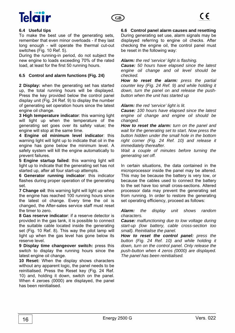
and all its parts must be cold 2 Let the generating set cool off. 7.3 Checking the engine oil level • Unscrew the engine oil filler cap and clean the
dipstick (Fig. 26 Ref. 1). • Put the dipstick back in without screwing. • Take the dipstick out again, and make sure
that the engine oil level is between the two (min and max) notches. Should the oil level be below the minimum notch, restore the oil level using the recommended type of engine oil (refer to the engine user and maintenance manual).
• Put the dipstick and filler cap back on and screw tightly.
Do not fill to exceed the maximum level, as this could cause malfunctioning of the fuel pump and hence of the generating set.
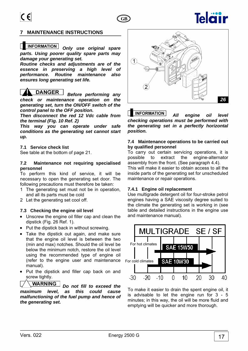
All engine oil level checking operations must be performed with the generating set in a perfectly horizontal position. 7.4 Maintenance operations to be carried out by qualified personnel To carry out certain servicing operations, it is possible to extract the engine-alternator assembly from the front. (See paragraph 4.4). This will make it easier to obtain access to all the inside parts of the generating set for unscheduled maintenance or repair operations. 7.4.1 Engine oil replacement Use multigrade detergent oil for four-stroke petrol engines having a SAE viscosity degree suited to the climate the generating set is working in (see table and detailed instructions in the engine use and maintenance manual).
To make it easier to drain the spent engine oil, it is advisable to let the engine run for 3 - 5 minutes; in this way, the oil will be more fluid and emptying will be quicker and more thorough.
26
For cold climates
For hot climates
Energy 2500 G Vers. 022
GB
18
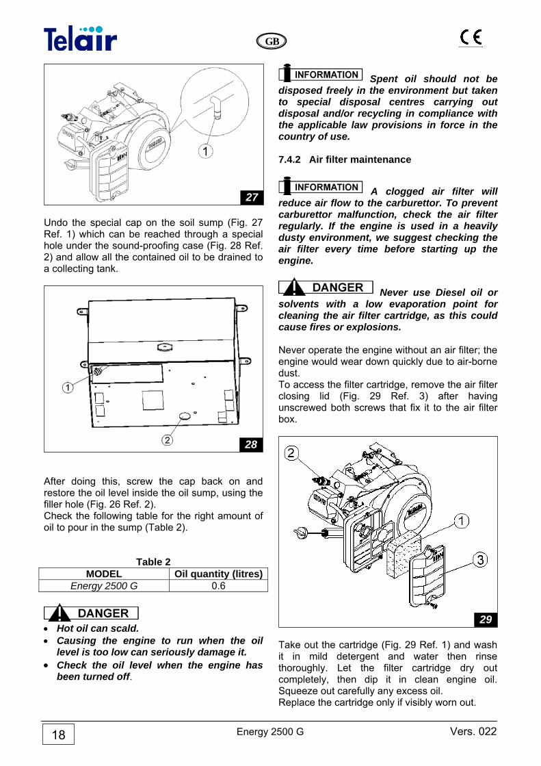
Undo the special cap on the soil sump (Fig. 27 Ref. 1) which can be reached through a special hole under the sound-proofing case (Fig. 28 Ref. 2) and allow all the contained oil to be drained to a collecting tank.
After doing this, screw the cap back on and restore the oil level inside the oil sump, using the filler hole (Fig. 26 Ref. 2). Check the following table for the right amount of oil to pour in the sump (Table 2).
Table 2 MODEL Oil quantity (litres)
Energy 2500 G 0.6
• Hot oil can scald. • Causing the engine to run when the oil
level is too low can seriously damage it. • Check the oil level when the engine has
been turned off.
Spent oil should not be disposed freely in the environment but taken to special disposal centres carrying out disposal and/or recycling in compliance with the applicable law provisions in force in the country of use. 7.4.2 Air filter maintenance
A clogged air filter will reduce air flow to the carburettor. To prevent carburettor malfunction, check the air filter regularly. If the engine is used in a heavily dusty environment, we suggest checking the air filter every time before starting up the engine.
Never use Diesel oil or solvents with a low evaporation point for cleaning the air filter cartridge, as this could cause fires or explosions. Never operate the engine without an air filter; the engine would wear down quickly due to air-borne dust. To access the filter cartridge, remove the air filter closing lid (Fig. 29 Ref. 3) after having unscrewed both screws that fix it to the air filter box.
Take out the cartridge (Fig. 29 Ref. 1) and wash it in mild detergent and water then rinse thoroughly. Let the filter cartridge dry out completely, then dip it in clean engine oil. Squeeze out carefully any excess oil. Replace the cartridge only if visibly worn out.
29
28
27
Vers. 022 Energy 2500 G
GB
19
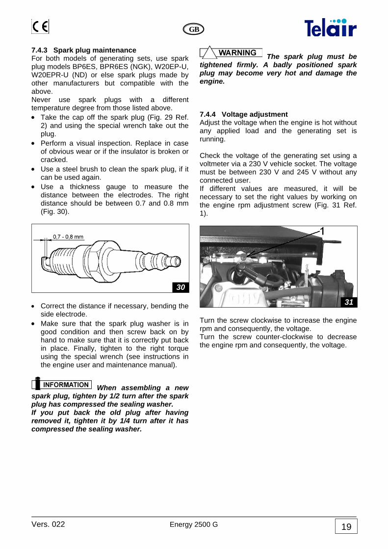
7.4.3 Spark plug maintenance For both models of generating sets, use spark plug models BP6ES, BPR6ES (NGK), W20EP-U, W20EPR-U (ND) or else spark plugs made by other manufacturers but compatible with the above. Never use spark plugs with a different temperature degree from those listed above. • Take the cap off the spark plug (Fig. 29 Ref.
2) and using the special wrench take out the plug.
• Perform a visual inspection. Replace in case of obvious wear or if the insulator is broken or cracked.
• Use a steel brush to clean the spark plug, if it can be used again.
• Use a thickness gauge to measure the distance between the electrodes. The right distance should be between 0.7 and 0.8 mm (Fig. 30).
• Correct the distance if necessary, bending the
side electrode. • Make sure that the spark plug washer is in
good condition and then screw back on by hand to make sure that it is correctly put back in place. Finally, tighten to the right torque using the special wrench (see instructions in the engine user and maintenance manual).
When assembling a new spark plug, tighten by 1/2 turn after the spark plug has compressed the sealing washer. If you put back the old plug after having removed it, tighten it by 1/4 turn after it has compressed the sealing washer.
The spark plug must be tightened firmly. A badly positioned spark plug may become very hot and damage the engine. 7.4.4 Voltage adjustment Adjust the voltage when the engine is hot without any applied load and the generating set is running. Check the voltage of the generating set using a voltmeter via a 230 V vehicle socket. The voltage must be between 230 V and 245 V without any connected user. If different values are measured, it will be necessary to set the right values by working on the engine rpm adjustment screw (Fig. 31 Ref. 1).
Turn the screw clockwise to increase the engine rpm and consequently, the voltage. Turn the screw counter-clockwise to decrease the engine rpm and consequently, the voltage.
31
30
Energy 2500 G Vers. 022
GB
20
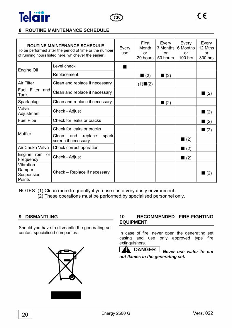
8 ROUTINE MAINTENANCE SCHEDULE
ROUTINE MAINTENANCE SCHEDULE To be performed after the period of time or the number of running hours listed here, whichever the earlier.
Every use
First Month
or 20 hours
Every 3 Months
or 50 hours
Every 6 Months
or 100 hrs
Every 12 Mths
or 300 hrs
Level check ■ Engine Oil
Replacement ■ (2) ■ (2)
Air Filter Clean and replace if necessary (1)■(2) Fuel Filter and Tank Clean and replace if necessary ■ (2)
Spark plug Clean and replace if necessary ■ (2) Valve Adjustment Check - Adjust ■ (2)
Fuel Pipe Check for leaks or cracks ■ (2)
Check for leaks or cracks ■ (2) Muffler Clean and replace spark
screen if necessary ■ (2)
Air Choke Valve Check correct operation ■ (2) Engine rpm or Frequency Check - Adjust ■ (2)
Vibration Damper Suspension Points
Check – Replace if necessary ■ (2)
NOTES: (1) Clean more frequently if you use it in a very dusty environment. (2) These operations must be performed by specialised personnel only. 9 DISMANTLING Should you have to dismantle the generating set, contact specialised companies.
10 RECOMMENDED FIRE-FIGHTING EQUIPMENT In case of fire, never open the generating set casing and use only approved type fire extinguishers.
Never use water to put out flames in the generating set.

Vers. 022 Energy 2500 G
GB
21
GENERAL WARRANTY TERMS TELAIR guarantees its products against any construction material and/or manufacturing faults and defects. The right to warranty cover for new engines is valid for a period of 24 months from the time of handing over to the end user, or for a maximum of 2000 operating hours, whichever limit is reached first. In all cases the warranty period shall end no later than 26 months (28 months if delivered outside of Europe) after ex factory delivery. For electric and hydraulic components, pipes, belts, sealing elements, injection nozzles, clutches, drives, the warranty term is 12 months from the time of handing over to the end user, or a maximum of 2000 operating hours, whichever limit is reached first. In all cases the warranty period shall end no later than 14 months (16 months if delivered outside of Europe) after ex factory delivery. In any case, the costs of lubricants and consumables shall be charged. Any transport expenses shall have to be covered by the purchaser; the same applies to any expenses connected with inspections requested by the customer and accepted by TELAIR. The manufacturer’s warranty shall only be valid if: • the customer has carried out all routine maintenance according to the
recommended schedule and has promptly visited the nearest after-sale centre if required.
• the customer can produce a document showing the date of sale (invoice or receipt).
Such document will have to be kept with care and be intact when produced to the TELAIR After-Sales centre on requesting service.
In any case, the purchaser shall not be entitled to: • terminate the contract; • claim damages to persons or property; • ask that the warranty be extended in the event of product defects or
malfunctioning.
Vers. 022 Energy 2500 G
GB
23
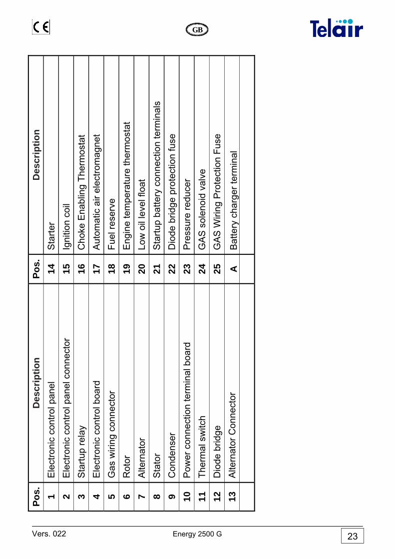
Des
crip
tion
Sta
rter
Igni
tion
coil
Cho
ke E
nabl
ing
Ther
mos
tat
Aut
omat
ic a
ir el
ectro
mag
net
Fuel
rese
rve
Eng
ine
tem
pera
ture
ther
mos
tat
Low
oil
leve
l flo
at
Sta
rtup
batte
ry c
onne
ctio
n te
rmin
als
Dio
de b
ridge
pro
tect
ion
fuse
P
ress
ure
redu
cer
GA
S s
olen
oid
valv
e G
AS
Wiri
ng P
rote
ctio
n Fu
se
Bat
tery
cha
rger
term
inal
Pos.
14
15
16
17
18
19
20
21
22
23
24
25
A
Des
crip
tion
Ele
ctro
nic
cont
rol p
anel
E
lect
roni
c co
ntro
l pan
el c
onne
ctor
S
tartu
p re
lay
Ele
ctro
nic
cont
rol b
oard
G
as w
iring
con
nect
or
Rot
or
Alte
rnat
or
Sta
tor
Con
dens
er
Pow
er c
onne
ctio
n te
rmin
al b
oard
Th
erm
al s
witc
h D
iode
brid
ge
Alte
rnat
or C
onne
ctor
Pos.
1 2 3 4 5 6 7 8 9 10
11
12
13
Energy 2500 G Vers. 022
GB
24
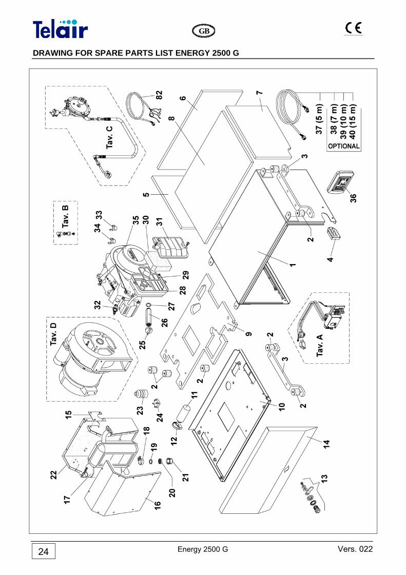
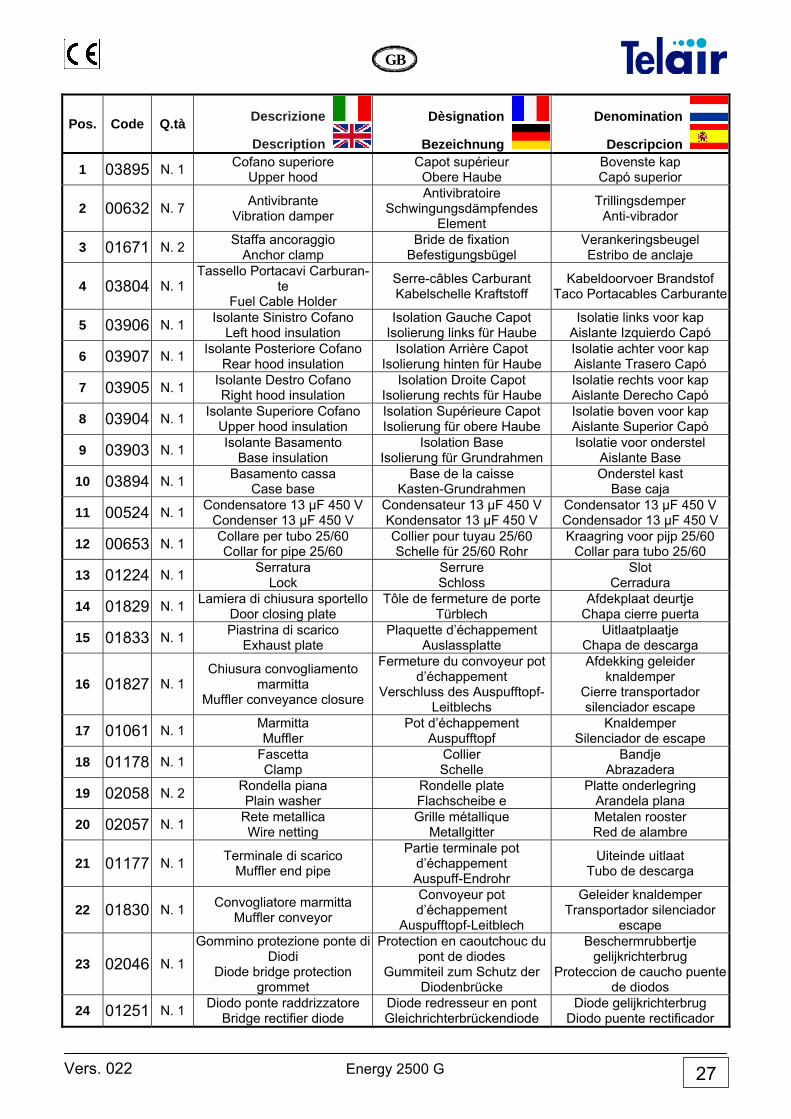
DRAWING FOR SPARE PARTS LIST ENERGY 2500 G
Vers. 022 Energy 2500 G
GB
25
Energy 2500 G Vers. 022
GB
26
Vers. 022 Energy 2500 G
GB
27
Pos. Code Q.tà Descrizione
Description
Dèsignation
Bezeichnung
Denomination
Descripcion
1 03895 N. 1 Cofano superiore Upper hood
Capot supérieur Obere Haube
Bovenste kap Capó superior
2 00632 N. 7 Antivibrante Vibration damper
Antivibratoire Schwingungsdämpfendes
Element
Trillingsdemper Anti-vibrador
3 01671 N. 2 Staffa ancoraggio Anchor clamp
Bride de fixation Befestigungsbügel
Verankeringsbeugel Estribo de anclaje
4 03804 N. 1 Tassello Portacavi Carburan-
te Fuel Cable Holder
Serre-câbles Carburant Kabelschelle Kraftstoff
Kabeldoorvoer Brandstof Taco Portacables Carburante
5 03906 N. 1 Isolante Sinistro Cofano Left hood insulation
Isolation Gauche Capot Isolierung links für Haube
Isolatie links voor kap Aislante Izquierdo Capó
6 03907 N. 1 Isolante Posteriore Cofano Rear hood insulation
Isolation Arrière Capot Isolierung hinten für Haube
Isolatie achter voor kap Aislante Trasero Capó
7 03905 N. 1 Isolante Destro Cofano Right hood insulation
Isolation Droite Capot Isolierung rechts für Haube
Isolatie rechts voor kap Aislante Derecho Capó
8 03904 N. 1 Isolante Superiore Cofano Upper hood insulation
Isolation Supérieure Capot Isolierung für obere Haube
Isolatie boven voor kap Aislante Superior Capó
9 03903 N. 1 Isolante Basamento Base insulation
Isolation Base Isolierung für Grundrahmen
Isolatie voor onderstel Aislante Base
10 03894 N. 1 Basamento cassa Case base
Base de la caisse Kasten-Grundrahmen
Onderstel kast Base caja
11 00524 N. 1 Condensatore 13 µF 450 V Condenser 13 µF 450 V
Condensateur 13 µF 450 V Kondensator 13 µF 450 V
Condensator 13 µF 450 V Condensador 13 µF 450 V
12 00653 N. 1 Collare per tubo 25/60 Collar for pipe 25/60
Collier pour tuyau 25/60 Schelle für 25/60 Rohr
Kraagring voor pijp 25/60 Collar para tubo 25/60
13 01224 N. 1 Serratura Lock
Serrure Schloss
Slot Cerradura
14 01829 N. 1 Lamiera di chiusura sportelloDoor closing plate
Tôle de fermeture de porte Türblech
Afdekplaat deurtje Chapa cierre puerta
15 01833 N. 1 Piastrina di scarico Exhaust plate
Plaquette d’échappement Auslassplatte
Uitlaatplaatje Chapa de descarga
16 01827 N. 1 Chiusura convogliamento
marmitta Muffler conveyance closure
Fermeture du convoyeur potd’échappement
Verschluss des Auspufftopf-Leitblechs
Afdekking geleider knaldemper
Cierre transportador silenciador escape
17 01061 N. 1 Marmitta Muffler
Pot d’échappement Auspufftopf
Knaldemper Silenciador de escape
18 01178 N. 1 Fascetta Clamp
Collier Schelle
Bandje Abrazadera
19 02058 N. 2 Rondella piana Plain washer
Rondelle plate Flachscheibe e
Platte onderlegring Arandela plana
20 02057 N. 1 Rete metallica Wire netting
Grille métallique Metallgitter
Metalen rooster Red de alambre
21 01177 N. 1 Terminale di scarico Muffler end pipe
Partie terminale pot d’échappement Auspuff-Endrohr
Uiteinde uitlaat Tubo de descarga
22 01830 N. 1 Convogliatore marmitta Muffler conveyor
Convoyeur pot d’échappement
Auspufftopf-Leitblech
Geleider knaldemper Transportador silenciador
escape
23 02046 N. 1
Gommino protezione ponte di Diodi
Diode bridge protection grommet
Protection en caoutchouc du pont de diodes
Gummiteil zum Schutz der Diodenbrücke
Beschermrubbertje gelijkrichterbrug
Proteccion de caucho puente de diodos
24 01251 N. 1 Diodo ponte raddrizzatore Bridge rectifier diode
Diode redresseur en pont Gleichrichterbrückendiode
Diode gelijkrichterbrug Diodo puente rectificador
Energy 2500 G Vers. 022
GB
28
Pos. Code Q.tà Descrizione
Description
Dèsignation
Bezeichnung
Denomination
Descripcion
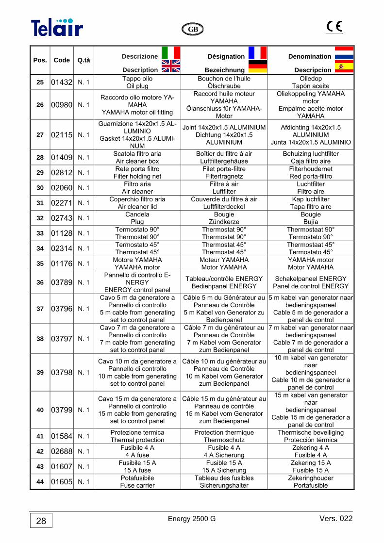
25 01432 N. 1 Tappo olio Oil plug
Bouchon de l’huile Ölschraube
Oliedop Tapón aceite
26 00980 N. 1 Raccordo olio motore YA-
MAHA YAMAHA motor oil fitting
Raccord huile moteur YAMAHA
Ölanschluss für YAMAHA-Motor
Oliekoppeling YAMAHA motor
Empalme aceite motor YAMAHA
27 02115 N. 1
Guarnizione 14x20x1.5 AL-LUMINIO
Gasket 14x20x1.5 ALUMI-NUM
Joint 14x20x1.5 ALUMINIUMDichtung 14x20x1.5
ALUMINIUM
Afdichting 14x20x1.5 ALUMINIUM
Junta 14x20x1.5 ALUMINIO
28 01409 N. 1 Scatola filtro aria Air cleaner box
Boîtier du filtre à air Luftfiltergehäuse
Behuizing luchtfilter Caja filtro aire
29 02812 N. 1 Rete porta filtro Filter holding net
Filet porte-filtre Filtertragnetz
Filterhoudernet Red porta-filtro
30 02060 N. 1 Filtro aria Air cleaner
Filtre à air Luftfilter
Luchtfilter Filtro aire
31 02271 N. 1 Coperchio filtro aria Air cleaner lid
Couvercle du filtre à air Luftfilterdeckel
Kap luchfilter Tapa filtro aire
32 02743 N. 1 Candela Plug
Bougie Zündkerze
Bougie Bujía
33 01128 N. 1 Termostato 90° Thermostat 90°
Thermostat 90° Thermostat 90°
Thermostaat 90° Termostato 90°
34 02314 N. 1 Termostato 45° Thermostat 45°
Thermostat 45° Thermostat 45°
Thermostaat 45° Termostato 45°
35 01176 N. 1 Motore YAMAHA YAMAHA motor
Moteur YAMAHA Motor YAMAHA
YAMAHA motor Motor YAMAHA
36 03789 N. 1 Pannello di controllo E-
NERGY ENERGY control panel
Tableau/contrôle ENERGY Bedienpanel ENERGY
Schakelpaneel ENERGY Panel de control ENERGY
37 03796 N. 1
Cavo 5 m da generatore a Pannello di controllo
5 m cable from generating set to control panel
Câble 5 m du Générateur au Panneau de Contrôle
5 m Kabel von Generator zu Bedienpanel
5 m kabel van generator naar bedieningspaneel
Cable 5 m de generador a panel de control
38 03797 N. 1
Cavo 7 m da generatore a Pannello di controllo
7 m cable from generating set to control panel
Câble 7 m du générateur au Panneau de Contrôle
7 m Kabel vom Generator zum Bedienpanel
7 m kabel van generator naar bedieningspaneel
Cable 7 m de generador a panel de control
39 03798 N. 1
Cavo 10 m da generatore a Pannello di controllo
10 m cable from generating set to control panel
Câble 10 m du générateur au Panneau de Contrôle
10 m Kabel vom Generator zum Bedienpanel
10 m kabel van generator naar
bedieningspaneel Cable 10 m de generador a
panel de control
40 03799 N. 1
Cavo 15 m da generatore a Pannello di controllo
15 m cable from generating set to control panel
Câble 15 m du générateur au Panneau de contrôle
15 m Kabel vom Generator zum Bedienpanel
15 m kabel van generator naar
bedieningspaneel Cable 15 m de generador a
panel de control
41 01584 N. 1 Protezione termica Thermal protection
Protection thermique Thermoschutz
Thermische beveiliging Protección térmica
42 02688 N. 1 Fusibile 4 A 4 A fuse
Fusible 4 A 4 A Sicherung
Zekering 4 A Fusible 4 A
43 01607 N. 1 Fusibile 15 A 15 A fuse
Fusible 15 A 15 A Sicherung
Zekering 15 A Fusible 15 A
44 01605 N. 1 Potafusibile Fuse carrier
Tableau des fusibles Sicherungshalter
Zekeringhouder Portafusible
Vers. 022 Energy 2500 G
GB
29
Pos. Code Q.tà Descrizione
Description
Dèsignation
Bezeichnung
Denomination
Descripcion
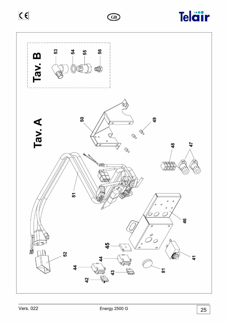
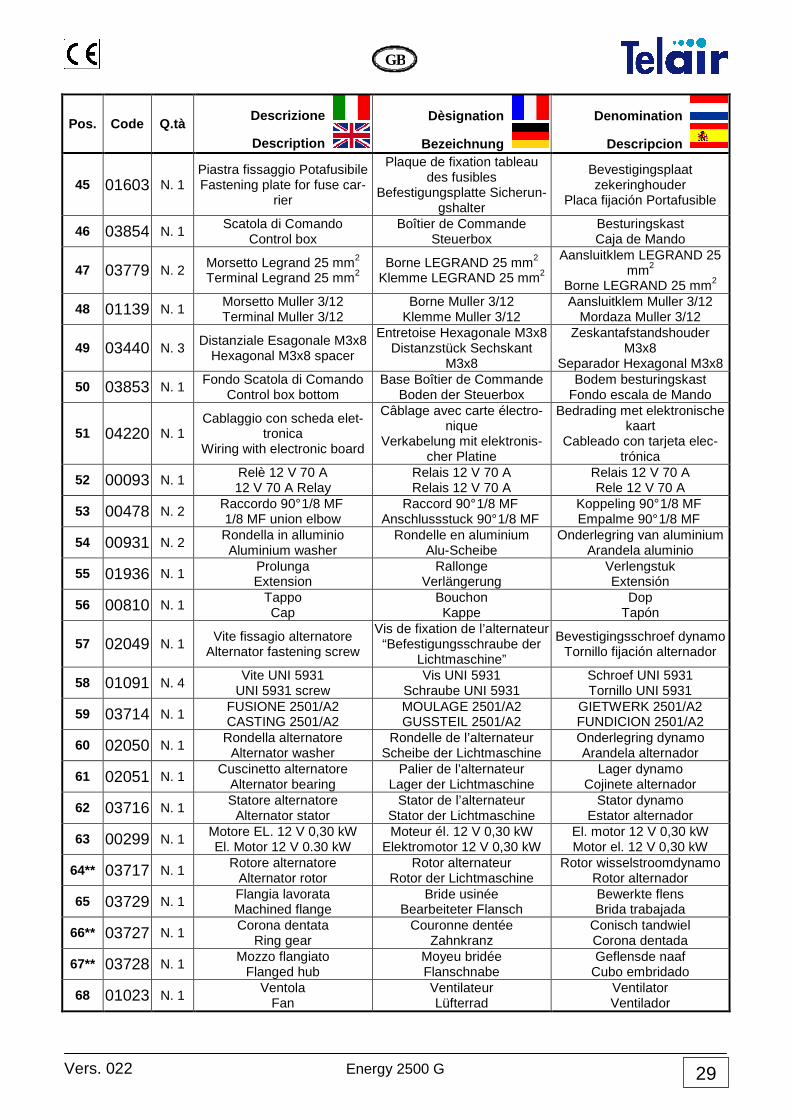
45 01603 N. 1 Piastra fissaggio Potafusibile Fastening plate for fuse car-
rier
Plaque de fixation tableau des fusibles
Befestigungsplatte Sicherun-gshalter
Bevestigingsplaat zekeringhouder
Placa fijación Portafusible
46 03854 N. 1 Scatola di Comando
Control box Boîtier de Commande
Steuerbox Besturingskast Caja de Mando
47 03779 N. 2 Morsetto Legrand 25 mm2 Terminal Legrand 25 mm2
Borne LEGRAND 25 mm2 Klemme LEGRAND 25 mm2
Aansluitklem LEGRAND 25 mm2
Borne LEGRAND 25 mm2
48 01139 N. 1 Morsetto Muller 3/12 Terminal Muller 3/12
Borne Muller 3/12 Klemme Muller 3/12
Aansluitklem Muller 3/12 Mordaza Muller 3/12
49 03440 N. 3 Distanziale Esagonale M3x8
Hexagonal M3x8 spacer
Entretoise Hexagonale M3x8 Distanzstück Sechskant
M3x8
Zeskantafstandshouder M3x8
Separador Hexagonal M3x8
50 03853 N. 1 Fondo Scatola di Comando
Control box bottom Base Boîtier de Commande
Boden der Steuerbox Bodem besturingskast
Fondo escala de Mando
51 04220 N. 1 Cablaggio con scheda elet-
tronica Wiring with electronic board
Câblage avec carte électro-nique
Verkabelung mit elektronis-cher Platine
Bedrading met elektronische kaart
Cableado con tarjeta elec-trónica
52 00093 N. 1 Relè 12 V 70 A 12 V 70 A Relay
Relais 12 V 70 A Relais 12 V 70 A
Relais 12 V 70 A Rele 12 V 70 A
53 00478 N. 2 Raccordo 90° 1/8 MF 1/8 MF union elbow
Raccord 90° 1/8 MF Anschlussstuck 90° 1/8 MF
Koppeling 90° 1/8 MF Empalme 90° 1/8 MF
54 00931 N. 2 Rondella in alluminio Aluminium washer
Rondelle en aluminium Alu-Scheibe
Onderlegring van aluminium Arandela aluminio
55 01936 N. 1 Prolunga Extension
Rallonge Verlängerung
Verlengstuk Extensión
56 00810 N. 1 Tappo Cap
Bouchon Kappe
Dop Tapón
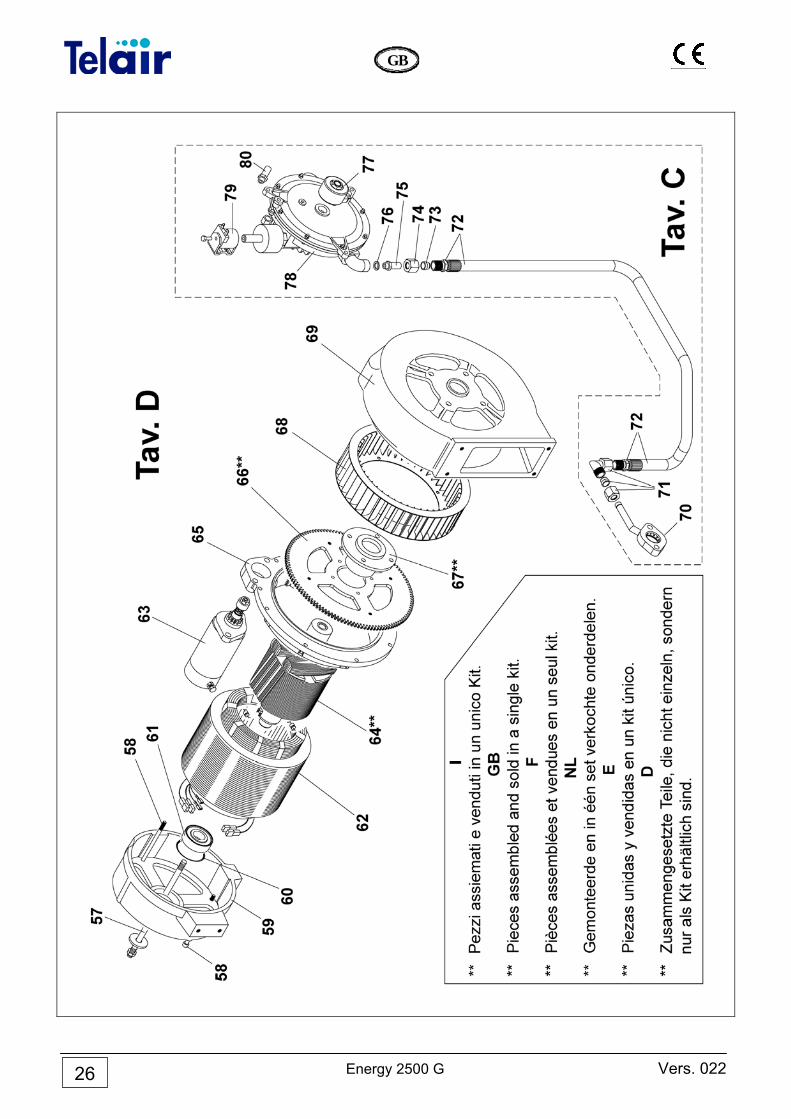
57 02049 N. 1 Vite fissagio alternatore
Alternator fastening screw
Vis de fixation de l’alternateur “Befestigungsschraube der
Lichtmaschine”
Bevestigingsschroef dynamo Tornillo fijación alternador
58 01091 N. 4 Vite UNI 5931
UNI 5931 screw Vis UNI 5931
Schraube UNI 5931 Schroef UNI 5931 Tornillo UNI 5931
59 03714 N. 1 FUSIONE 2501/A2 CASTING 2501/A2
MOULAGE 2501/A2 GUSSTEIL 2501/A2
GIETWERK 2501/A2 FUNDICION 2501/A2
60 02050 N. 1 Rondella alternatore
Alternator washer Rondelle de l’alternateur
Scheibe der Lichtmaschine Onderlegring dynamo Arandela alternador
61 02051 N. 1 Cuscinetto alternatore
Alternator bearing Palier de l’alternateur
Lager der Lichtmaschine Lager dynamo
Cojinete alternador
62 03716 N. 1 Statore alternatore
Alternator stator Stator de l’alternateur
Stator der Lichtmaschine Stator dynamo
Estator alternador
63 00299 N. 1 Motore EL. 12 V 0,30 kW El. Motor 12 V 0.30 kW
Moteur él. 12 V 0,30 kW Elektromotor 12 V 0,30 kW
El. motor 12 V 0,30 kW Motor el. 12 V 0,30 kW
64** 03717 N. 1 Rotore alternatore
Alternator rotor Rotor alternateur
Rotor der Lichtmaschine Rotor wisselstroomdynamo
Rotor alternador
65 03729 N. 1 Flangia lavorata Machined flange
Bride usinée Bearbeiteter Flansch
Bewerkte flens Brida trabajada
66** 03727 N. 1 Corona dentata
Ring gear Couronne dentée
Zahnkranz Conisch tandwiel Corona dentada
67** 03728 N. 1 Mozzo flangiato
Flanged hub Moyeu bridée Flanschnabe
Geflensde naaf Cubo embridado
68 01023 N. 1 Ventola
Fan Ventilateur Lüfterrad
Ventilator Ventilador
Energy 2500 G Vers. 022
GB
30
Pos. Code Q.tà Descrizione
Description
Dèsignation
Bezeichnung
Denomination
Descripcion
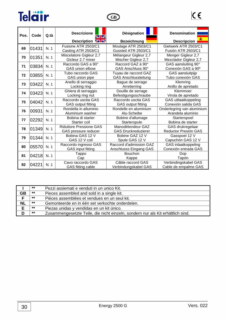
69 01431 N. 1 Fusione ATR 2503/C1 Casting ATR 2503/C1
Moulage ATR 2503/C1 Gussteil ATR 2503/C1
Gietwerk ATR 2503/C1 Fusión ATR 2503/C1
70 01351 N. 1 Miscelatore Gigleur 2,7
Gicleur 2.7 mixer Mélangeur Gigleur 2,7
Mischer Gigleur 2,7 Menger Gigleur 2,7
Mezclador Gigleur 2,7
71 03834 N. 1 Raccordo GAS a 90°
GAS union elbow Raccord GAZ à 90° GAS Anschluss 90°
GAS aansluiting 90° Conexión GAS a 90º
72 03855 N. 1 Tubo raccordo GAS
GAS union pipe Tuyau de raccord GAZ GAS Anschlussleitung
GAS aansluitpijp Tubo conexión GAS
73 03422 N. 1 Anello di serraggio
Locking ring Bague de serrage
Arretierring Klemring
Anillo de apretado
74 03423 N. 1 Ghiera di serraggio Locking ring nut
Douille de serrage Befestigungsschraube
Klemmoer Virola de apretado
75 04042 N. 1 Raccordo uscita GAS
GAS output fitting Raccordo uscita GAS
GAS output fitting GAS uitlaatkoppeling Conexión salida GAS
76 00931 N. 1 Rondella in alluminio Aluminium washer
Rondelle en aluminium Alu-Scheibe
Onderlegring van aluminium Arandela aluminio
77 02292 N. 1 Bobina di starter
Starter coil Bobine d'allumage
Starterspule Starterspoel
Bobina de starter
78 01349 N. 1 Riduttore Pressione GAS
GAS pressure reducer Manodétendeur GAZ GAS Druckreduzierer
GAS drukregelaar Reductor Presión GAS
79 01344 N. 1 Bobina GAS 12 V GAS 12 V coil
Bobine GAZ 12 V Spule GAS 12 V
Gasspoel 12 V Capuchón GAS 12 V
80 05570 N. 1 Raccordo ingresso GAS
GAS input fitting Raccord d'admission GAZ Anschlusss Eingang GAS
GAS inlaatkoppeling Conexión entrada GAS
81 04218 N. 1 Tappo Cap
Bouchon Kappe
Dop Tapón
82 04221 N. 1 Cavo raccordo GAS
GAS fitting cable Câble raccord GAS
Verbindungskabel GAS Verbindingskabel GAS
Cable de empalme GAS
I ** Pezzi assiemati e venduti in un unico Kit. GB ** Pieces assembled and sold in a single kit. F ** Pièces assemblées et vendues en un seul kit.
NL ** Gemonteerde en in één set verkochte onderdelen. E ** Piezas unidas y vendidas en un kit único. D ** Zusammengesetzte Teile, die nicht einzeln, sondern nur als Kit erhältlich sind.
Vers. 022 Energy 2500 G
GB
31
Notes
.....................................................................................................................................................................
.....................................................................................................................................................................
.....................................................................................................................................................................
.....................................................................................................................................................................
.....................................................................................................................................................................
.....................................................................................................................................................................
.....................................................................................................................................................................
.....................................................................................................................................................................
.....................................................................................................................................................................
.....................................................................................................................................................................
.....................................................................................................................................................................
.....................................................................................................................................................................
.....................................................................................................................................................................
.....................................................................................................................................................................
.....................................................................................................................................................................
.....................................................................................................................................................................
.....................................................................................................................................................................
.....................................................................................................................................................................
.....................................................................................................................................................................
.....................................................................................................................................................................
.....................................................................................................................................................................
.....................................................................................................................................................................
.....................................................................................................................................................................
.....................................................................................................................................................................

ITALY Via E.Majorana 49 48022 LUGO( RA ) Tel. + 39 0545 25037 Fax.+ 39 0545 32064 E-mail: [email protected] www.telecogroup.com ZIMMER TECHNIK FŐR MOBILE FREIZEIT Raiffeisenstr, 6 64347 Griesheim Tel. 06155 797873 - Fax. 06155 797871 [email protected]
IN EUROPE: GREAT BRITAIN - SCAN TERIEUR LTD 30, The Metro Centre, Tolpits Lane - Watford, Herts - England - WD18 9XG Tel. 01923 800353 - Fax 01923 220358 HOLLAND / BELGIUM - KARMAN TRADING Lagewed 54 – 3849 PE Hierden – the Netherlands Tel. 0341 722450 - Fax 0341 722451 e-mail: [email protected] web site: www.karmantrading.nl FRANCE - BLEYS JEAN-PHILIPPE 19, Rue de la Parcheminerie 18700 Aubigny sur Nere - France Tel.02 48580367 – Fax 02 48583585 e-mail: [email protected] Service Technique France : 06 83 31 44 05 ESPAÑA - NAUCCA CARAVANING, S.A. Poligono Industrial CAN ROQUETA 2 – Calle Can Lletget,2 08202 Sabadell (Barcelona) - España Tel. 00 34 937 457 054 - Fax. 00 34 937 254 484 e-mail: [email protected] ÖSTERREICH – TELECO GmbH 82041 Deisenhofen - Deutshland Tel. 0049 8031 98939 - Fax. 0049 8031 98949 e-mail: [email protected] www.telecogroup.com IN DEUTSHLAND TELECO GmbH 82041 Deisenhofen - Tel. 0049 8031 98939 - Fax. 0049 8031 98949 e-mail: [email protected] www.telecogroup.com
Service für Teleco Anlagen in Deutschland:
09001000690
Service für Teleco Anlagen in Österreich:
0900949470
Foto e disegni non contrattuali - Les photos et les dessins ne sont donnés qu’à titre indicatif. We reserve the right to make technical changes without prior notice - Fotos und Zeichnungen nicht vertraglich.
Foto’s en tekeningen niet contractueel - Fotos y planos no indicados en contrato