Embed Size (px)
Citation preview
PA
GE
1GENERAL INFORMATION
GMMDGI Rev. 12/98
PROCEDURE FOR HANDLING CHASSIS/DEALER CLAIMS
GeneralAll chassis tendered for delivery by the Transportation Company are to be accepted bythe Body Company. If a chassis has been damaged or is short certain parts when re-ceived by the Body Company, they will repair or replace missing parts, if possible, withtheir own or other local facilities and promptly forward the claim to the dealer.
If the Body Company or other local facilities are not adequate for replacing missing ordamaged parts, the Body Company will promptly notify the Dealer and hold damagedchassis awaiting his instructions. The Dealer must be notified promptly upon receipt ofa chassis on which a claim is in order giving the “model”, “engine number,” and “serialnumber” and what the damage or shortage consisted of. This is important since Chevro-let/GMC Truck cannot accept claims from the Dealer unless filed within thirty days fromdate of delivery, or unless within the thirty-day period, the Dealer has advised Chevrolet/GMC Truck that a claim will be filed. Delivery to the Body Company constitutes deliveryto the Dealer, since the Body Company is the Dealer’s agent.
Completed vehicles that are to be driven to the Dealer or the Dealer’s customer mustfirst be serviced by the Body Company at the Body Company’s location in accordancewith Chevrolet/GMC Truck new vehicle conditioning procedures. Expenses incurred forthis condition are the responsibility of the selling Dealer.
Shipments Received from Truckaway or Driveaway CompanyThe Body Company will inspect condition of chassis and call driver’s attention to damageor missing parts and make a detailed notation of both copies of Transportation Compa-ny’s delivery receipt of the nature and extent of the existing damage and/or shortage andhave driver sign such notation on the Dealer’s copy. If chassis are received after busi-ness hours and cannot, therefore, be adequately inspected, the delivery receipt (bothcopies) is to carry notation “Received subject to inspection” and show the time and date.On such chassis, a detailed inspection must be made within 24 hours or on the first work-ing day after receipt of chassis and immediately furnish to the Dealer. Any exceptionsare to be noted on both copies of the delivery receipt by the Body Company.
If Received from RailroadFreight car should be opened and contents inspected in presence of railroad representa-tive before starting to unload, and any existing damage or shortage recorded by the rail-road representative on his standard inspection report. Body Company must secure fromrailroad agent, a copy of his inspection report detailing nature and extent of the damageand/or shortage.
If the railroad representative does not comply with consignee’s request to make an in-spection, then the Body Company will immediately confirm his request (in writing) to therailroad agent, outlining the nature and extent of damage and/or shortage disclosed byconsignee’s inspection, prior to starting any unloading operations, sending a copy of hisletter to the Dealer.
Filing a ClaimUpon completion of repairs or replacements of missing parts, the Body Company willpromptly bill the Dealer for the cost involved, supporting such debit with a detailed state-ment showing how the amount is arrived at end either the original delivery receipt withnotation if received from a truckaway company or the carrier’s inspection report if re-ceived from a railroad.
Disposition of Damaged PartsDamaged parts removed from chassis by the Body Company must be held for disposi-tion orders from the Dealer.
Dealer claims will not be allowed unless above instructions are fully compliedwith.
GOVERNMENT REGULATIONS
Introduction
The Federal Government has established Motor Vehicle Safety Standards for variouscategories of motor vehicles and motor vehicle equipment under the provisions of theNational Traffic and Motor Vehicle Safety Act of 1966. The Act imposes important legalresponsibilities on manufacturers, dealers, body builders and others engaged in themanufacturing and marketing of motor vehicles and motor vehicle equipment.
Questions dealing with the specific application of the Act or the standards to your busi-ness should be discussed with your legal counsel. This is particularly so because thestandards and other requirements or interpretations are subject to change by the gov-ernment agency in charge, the National Highway Traffic Safety Administration.
New standards and amendments issued by the National Highway Traffic Safety Adminis-tration will appear in the Federal Register from time to time. You may obtain the FederalRegister, through the Superintendent of Documents, U.S. Government Printing Office,Washington, D.C. 20402.
PA
GE
1ELECTRICAL– DIESEL
ED Rev. 12/98
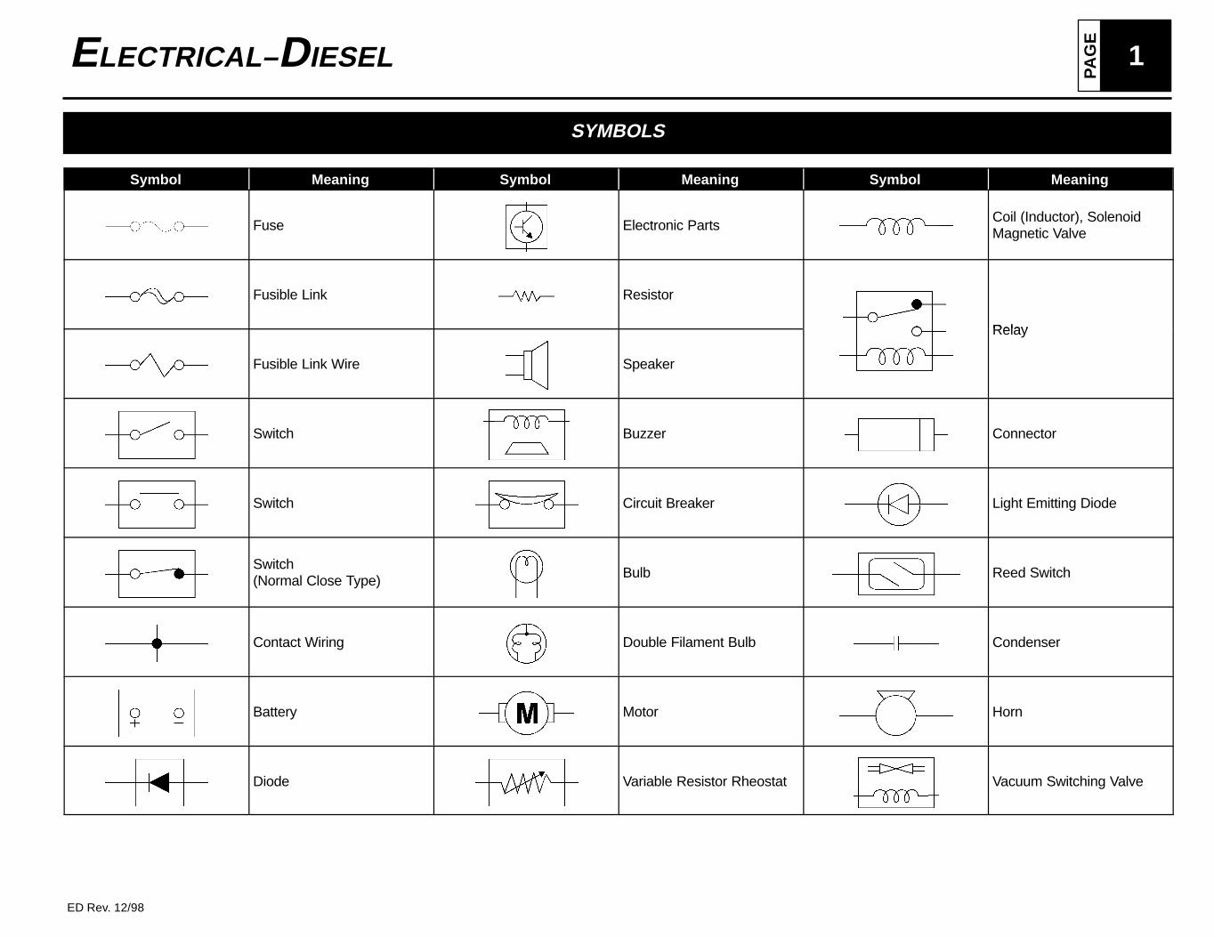
SYMBOLS
Symbol Meaning Symbol Meaning Symbol Meaning
Fuse Electronic PartsCoil (Inductor), SolenoidMagnetic Valve
Fusible Link Resistor
Relay
Fusible Link Wire Speaker
Relay
Switch Buzzer Connector
Switch Circuit Breaker Light Emitting Diode
Switch(Normal Close Type) Bulb Reed Switch
Contact Wiring Double Filament Bulb Condenser
Battery Motor Horn
Diode Variable Resistor Rheostat Vacuum Switching Valve
PA
GE2 ELECTRICAL– DIESEL
ED Rev. 12/98
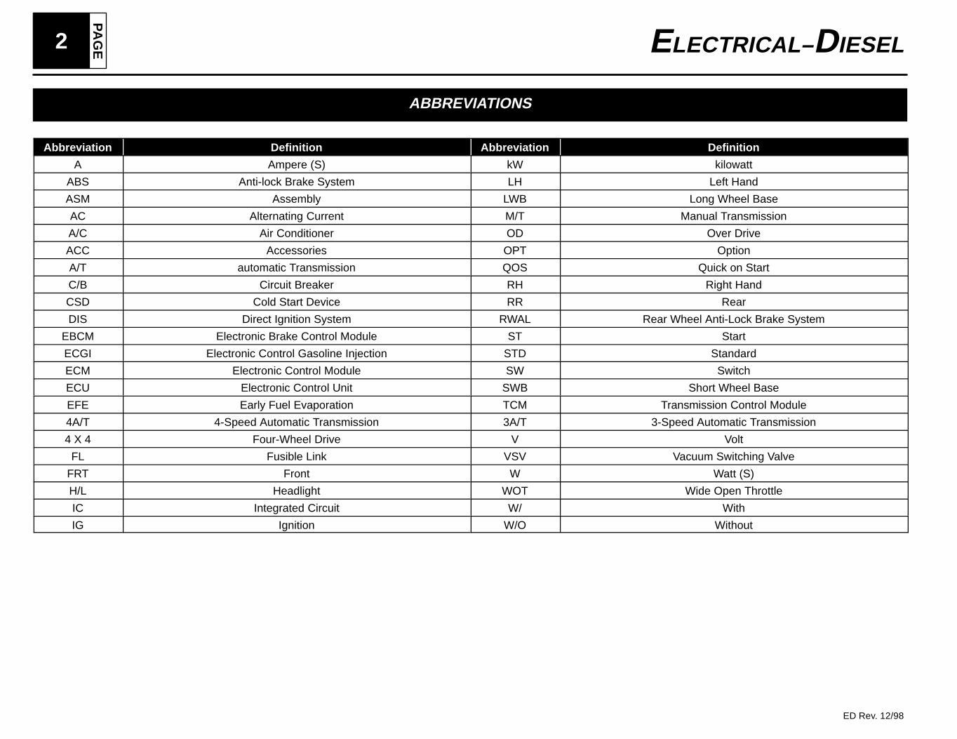
ABBREVIATIONS
Abbreviation Definition Abbreviation Definition
A Ampere (S) kW kilowatt
ABS Anti-lock Brake System LH Left Hand
ASM Assembly LWB Long Wheel Base
AC Alternating Current M/T Manual Transmission
A/C Air Conditioner OD Over Drive
ACC Accessories OPT Option
A/T automatic Transmission QOS Quick on Start
C/B Circuit Breaker RH Right Hand
CSD Cold Start Device RR Rear
DIS Direct Ignition System RWAL Rear Wheel Anti-Lock Brake System
EBCM Electronic Brake Control Module ST Start
ECGI Electronic Control Gasoline Injection STD Standard
ECM Electronic Control Module SW Switch
ECU Electronic Control Unit SWB Short Wheel Base
EFE Early Fuel Evaporation TCM Transmission Control Module
4A/T 4-Speed Automatic Transmission 3A/T 3-Speed Automatic Transmission
4 X 4 Four-Wheel Drive V Volt
FL Fusible Link VSV Vacuum Switching Valve
FRT Front W Watt (S)
H/L Headlight WOT Wide Open Throttle
IC Integrated Circuit W/ With
IG Ignition W/O Without
PA
GE
3ELECTRICAL– DIESEL
ED Rev. 12/98
WIRING
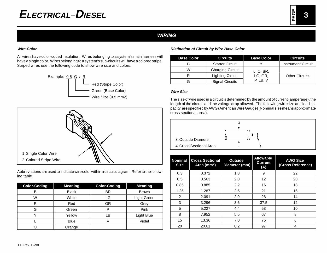
Wire Color
All wires have color-coded insulation. Wires belonging to a system’s main harness willhave a single color. Wires belonging to a system’s sub-circuits will have a colored stripe.Striped wires use the following code to show wire size and colors.
Example: 0.5 G / R
Red (Stripe Color)
Green (Base Color)
Wire Size (0.5 mm2)
1. Single Color Wire
2. Colored Stripe Wire
Abbreviations are used to indicate wire color within a circuit diagram. Refer to the follow-ing table
Color-Coding Meaning Color-Coding Meaning
B Black BR Brown
W White LG Light Green
R Red GR Grey
G Green P Pink
Y Yellow LB Light Blue
L Blue V Violet
O Orange
Distinction of Circuit by Wire Base Color
Base Color Circuits Base Color Circuits
B Starter Circuit Y Instrument Circuit
W Charging Circuit L, O, BR,R Lighting Circuit
L, O, BR,LG, GR, Other Circuits
G Signal Circuits
, ,P, LB, V
Ot e C cu ts
Wire Size
The size of wire used in a circuit is determined by the amount of current (amperage), thelength of the circuit, and the voltage drop allowed. The following wire size and load ca-pacity, are specified by AWG (American Wire Gauge) (Nominal size means approximatecross sectional area).
3. Outside Diameter
4. Cross Sectional Area
Nominal Size
Cross SectionalArea (mm 2)
Outside Diameter (mm)
Allowable Current
(A)
AWG Size (Cross Reference)
0.3 0.372 1.8 9 22
0.5 0.563 2.0 12 20
0.85 0.885 2.2 16 18
1.25 1.287 2.5 21 16
2 2.091 2.9 28 14
3 3.296 3.6 37.5 12
5 5.227 4.4 53 10
8 7.952 5.5 67 8
15 13.36 7.0 75 6
20 20.61 8.2 97 4
PA
GE4 ELECTRICAL– DIESEL
ED Rev. 12/98
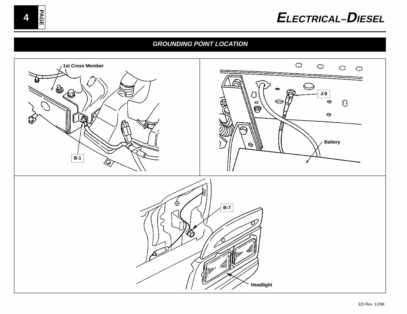
GROUNDING POINT LOCATION
1st Cross Member
B-1
Battery
J-9
B-7
Headlight
PA
GE
5ELECTRICAL– DIESEL
ED Rev. 12/98
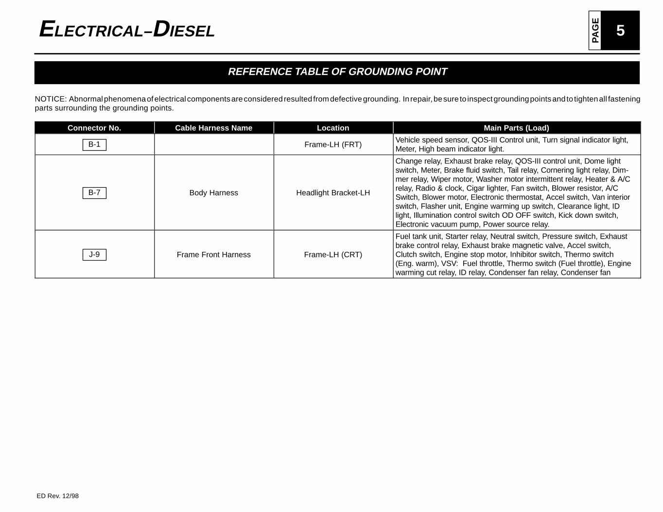
REFERENCE TABLE OF GROUNDING POINT
NOTICE: Abnormal phenomena of electrical components are considered resulted from defective grounding. In repair, be sure to inspect grounding points and to tighten all fasteningparts surrounding the grounding points.
Connector No. Cable Harness Name Location Main Parts (Load)
B-1 Frame-LH (FRT)Vehicle speed sensor, QOS-III Control unit, Turn signal indicator light,Meter, High beam indicator light.
B-7 Body Harness Headlight Bracket-LH
Change relay, Exhaust brake relay, QOS-III control unit, Dome lightswitch, Meter, Brake fluid switch, Tail relay, Cornering light relay, Dim-mer relay, Wiper motor, Washer motor intermittent relay, Heater & A/Crelay, Radio & clock, Cigar lighter, Fan switch, Blower resistor, A/CSwitch, Blower motor, Electronic thermostat, Accel switch, Van interiorswitch, Flasher unit, Engine warming up switch, Clearance light, IDlight, Illumination control switch OD OFF switch, Kick down switch,Electronic vacuum pump, Power source relay.
J-9 Frame Front Harness Frame-LH (CRT)
Fuel tank unit, Starter relay, Neutral switch, Pressure switch, Exhaustbrake control relay, Exhaust brake magnetic valve, Accel switch,Clutch switch, Engine stop motor, Inhibitor switch, Thermo switch(Eng. warm), VSV: Fuel throttle, Thermo switch (Fuel throttle), Enginewarming cut relay, ID relay, Condenser fan relay, Condenser fan
PA
GE6 ELECTRICAL– DIESEL
ED Rev. 12/98
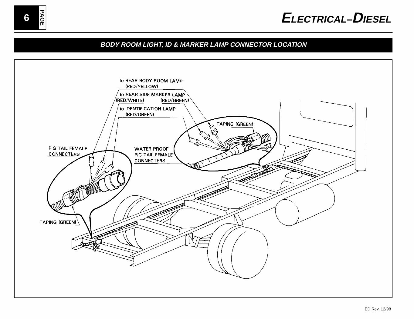
BODY ROOM LIGHT, ID & MARKER LAMP CONNECTOR LOCATION
PA
GE
7ELECTRICAL– DIESEL
ED Rev. 12/98
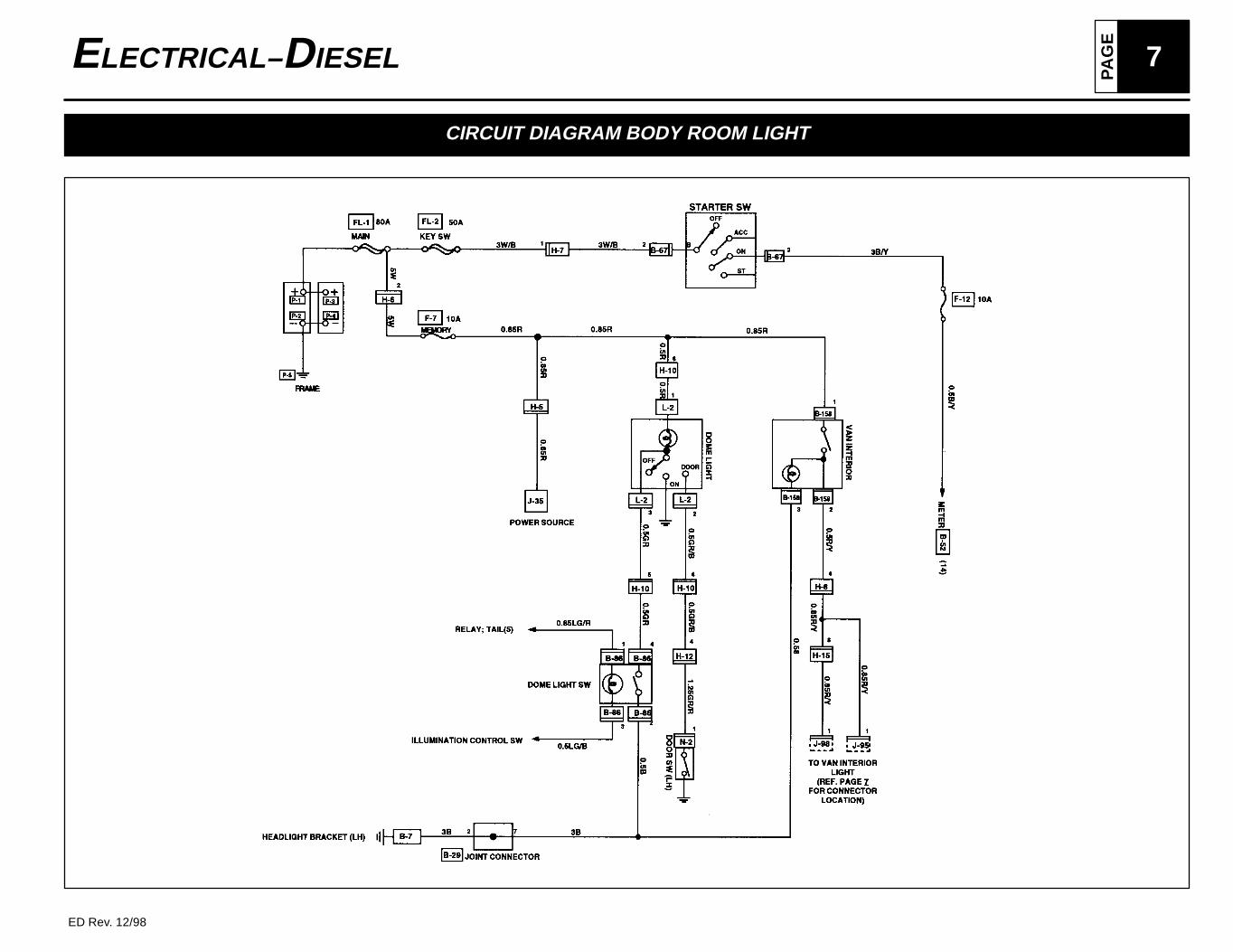
CIRCUIT DIAGRAM BODY ROOM LIGHT
PA
GE8 ELECTRICAL– DIESEL
ED Rev. 12/98
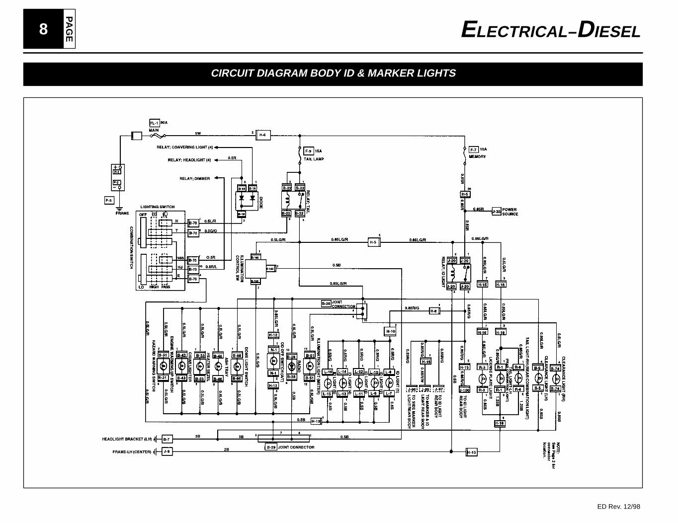
CIRCUIT DIAGRAM BODY ID & MARKER LIGHTS
PA
GE
9ELECTRICAL– DIESEL
ED Rev. 12/98
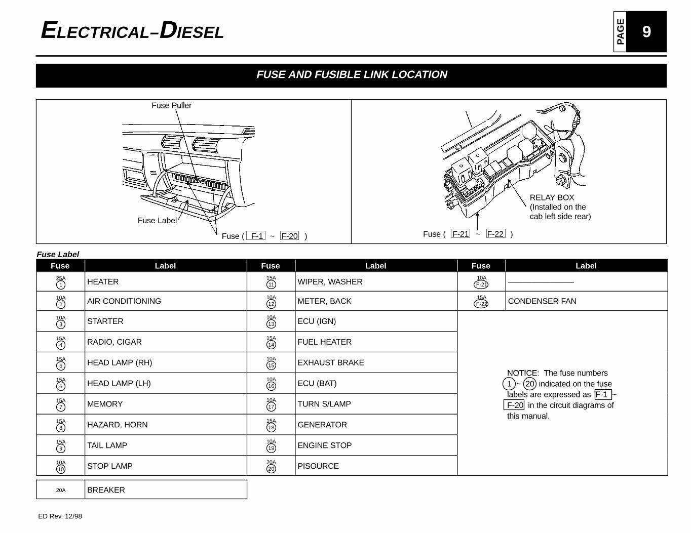
FUSE AND FUSIBLE LINK LOCATION
Fuse Puller
Fuse ( F-21 ~ F-22 )
RELAY BOX(Installed on thecab left side rear)Fuse Label
Fuse ( F-1 ~ F-20 )
Fuse LabelFuse Label Fuse Label Fuse Label
25A1 HEATER
15A11 WIPER, WASHER
10AF-21 –––––––––––––––
10A2 AIR CONDITIONING
10A12 METER, BACK
15AF-22 CONDENSER FAN
10A3 STARTER
10A13 ECU (IGN)
15A4 RADIO, CIGAR
15A14 FUEL HEATER
15A5 HEAD LAMP (RH)
10A15 EXHAUST BRAKE
NOTICE: The fuse numbers15A
6 HEAD LAMP (LH)10A16 ECU (BAT)
NOTICE: The fuse numbers1 ~ 20 indicated on the fuselabels are expressed as F 1
15A7 MEMORY
10A17 TURN S/LAMP
labels are expressed as F-1 ~F-20 in the circuit diagrams ofthi l
15A8 HAZARD, HORN
15A18 GENERATOR
this manual.
15A9 TAIL LAMP
10A19 ENGINE STOP
10A10 STOP LAMP
20A20 PISOURCE
20A BREAKER
PA
GE10 ELECTRICAL– DIESEL
ED Rev. 12/98
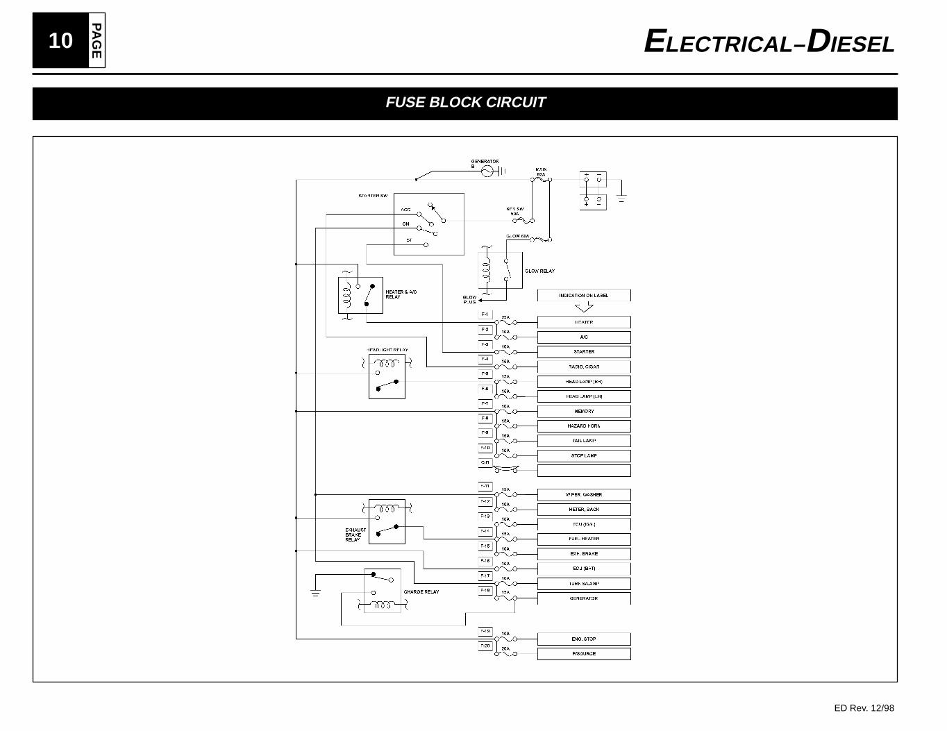
FUSE BLOCK CIRCUIT
PA
GE
11ELECTRICAL– DIESEL
ED Rev. 12/98
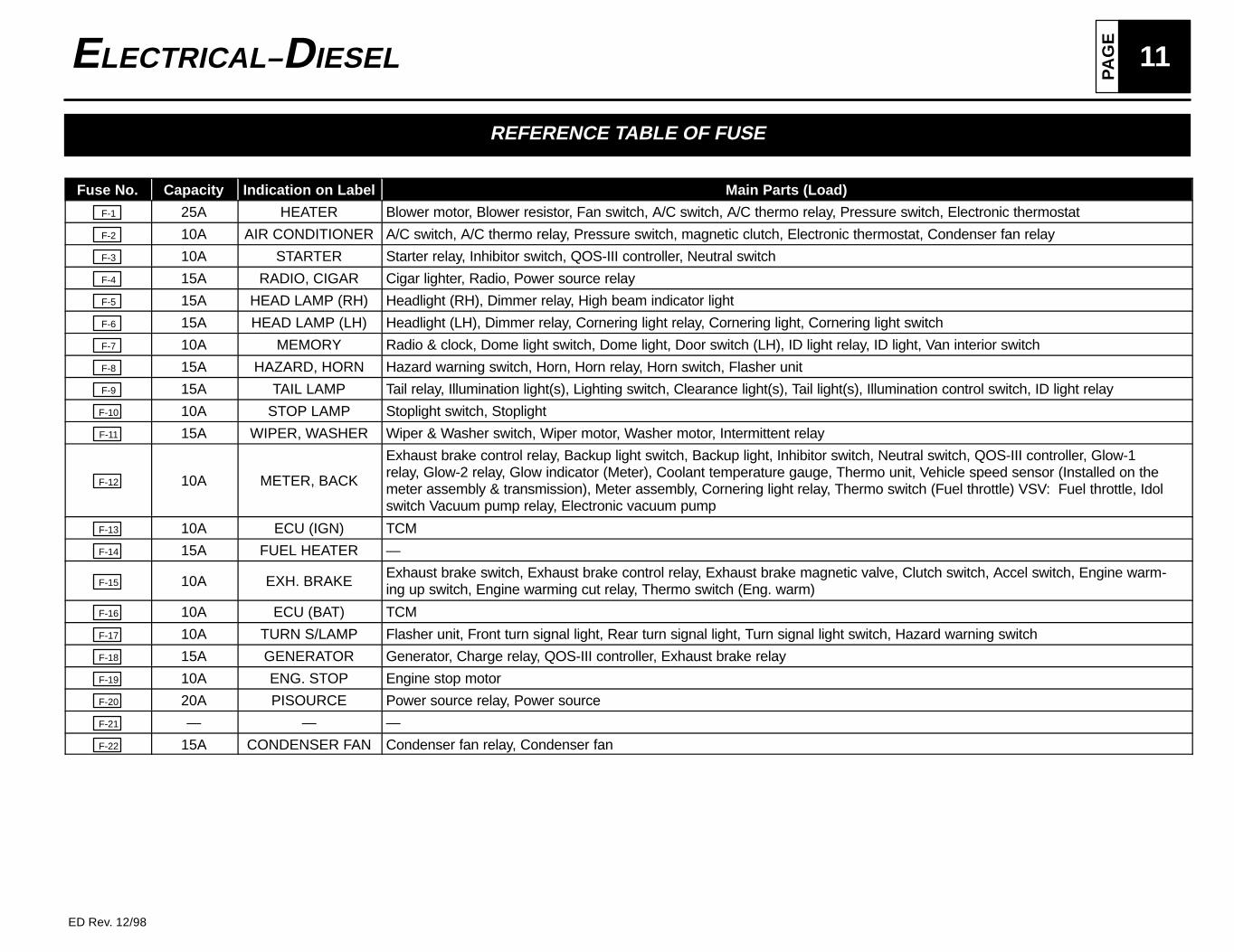
REFERENCE TABLE OF FUSE
Fuse No. Capacity Indication on Label Main Parts (Load)
F-1 25A HEATER Blower motor, Blower resistor, Fan switch, A/C switch, A/C thermo relay, Pressure switch, Electronic thermostat
F-2 10A AIR CONDITIONER A/C switch, A/C thermo relay, Pressure switch, magnetic clutch, Electronic thermostat, Condenser fan relay
F-3 10A STARTER Starter relay, Inhibitor switch, QOS-III controller, Neutral switch
F-4 15A RADIO, CIGAR Cigar lighter, Radio, Power source relay
F-5 15A HEAD LAMP (RH) Headlight (RH), Dimmer relay, High beam indicator light
F-6 15A HEAD LAMP (LH) Headlight (LH), Dimmer relay, Cornering light relay, Cornering light, Cornering light switch
F-7 10A MEMORY Radio & clock, Dome light switch, Dome light, Door switch (LH), ID light relay, ID light, Van interior switch
F-8 15A HAZARD, HORN Hazard warning switch, Horn, Horn relay, Horn switch, Flasher unit
F-9 15A TAIL LAMP Tail relay, Illumination light(s), Lighting switch, Clearance light(s), Tail light(s), Illumination control switch, ID light relay
F-10 10A STOP LAMP Stoplight switch, Stoplight
F-11 15A WIPER, WASHER Wiper & Washer switch, Wiper motor, Washer motor, Intermittent relay
F-12 10A METER, BACK
Exhaust brake control relay, Backup light switch, Backup light, Inhibitor switch, Neutral switch, QOS-III controller, Glow-1relay, Glow-2 relay, Glow indicator (Meter), Coolant temperature gauge, Thermo unit, Vehicle speed sensor (Installed on themeter assembly & transmission), Meter assembly, Cornering light relay, Thermo switch (Fuel throttle) VSV: Fuel throttle, Idolswitch Vacuum pump relay, Electronic vacuum pump
F-13 10A ECU (IGN) TCM
F-14 15A FUEL HEATER —
F-15 10A EXH. BRAKEExhaust brake switch, Exhaust brake control relay, Exhaust brake magnetic valve, Clutch switch, Accel switch, Engine warm-ing up switch, Engine warming cut relay, Thermo switch (Eng. warm)
F-16 10A ECU (BAT) TCM
F-17 10A TURN S/LAMP Flasher unit, Front turn signal light, Rear turn signal light, Turn signal light switch, Hazard warning switch
F-18 15A GENERATOR Generator, Charge relay, QOS-III controller, Exhaust brake relay
F-19 10A ENG. STOP Engine stop motor
F-20 20A PISOURCE Power source relay, Power source
F-21 — — —
F-22 15A CONDENSER FAN Condenser fan relay, Condenser fan
PA
GE12 ELECTRICAL– DIESEL
ED Rev. 12/98
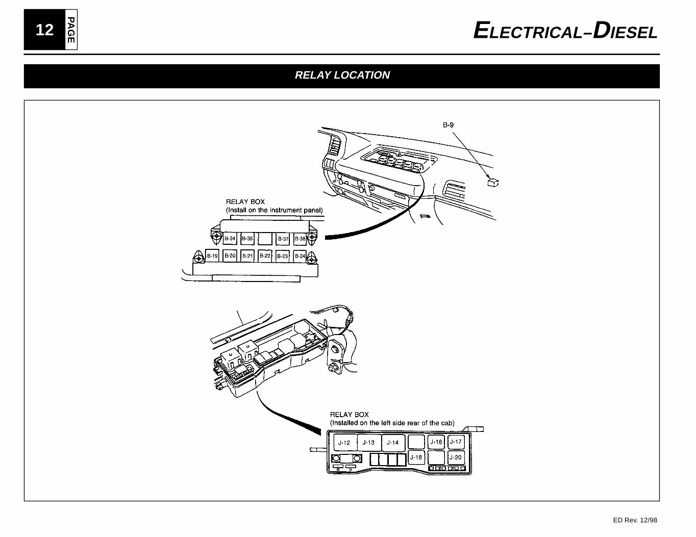
RELAY LOCATION
PA
GE
13ELECTRICAL– DIESEL
ED Rev. 12/98
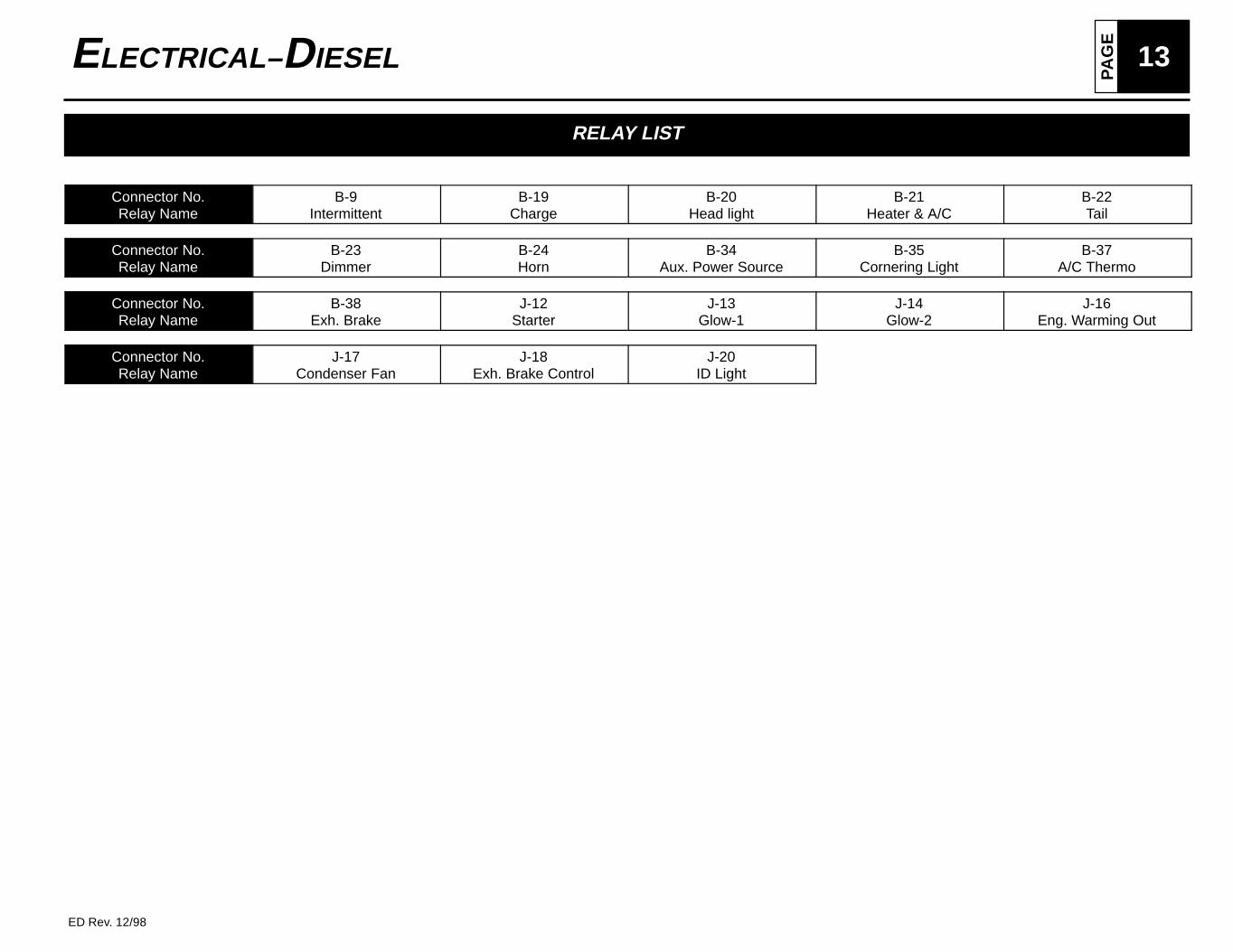
RELAY LIST
Connector No.Relay Name
B-9Intermittent
B-19Charge
B-20Head light
B-21Heater & A/C
B-22Tail
Connector No.Relay Name
B-23Dimmer
B-24Horn
B-34Aux. Power Source
B-35Cornering Light
B-37A/C Thermo
Connector No.Relay Name
B-38Exh. Brake
J-12Starter
J-13Glow-1
J-14Glow-2
J-16Eng. Warming Out
Connector No.Relay Name
J-17Condenser Fan
J-18Exh. Brake Control
J-20ID Light
PA
GE14 ELECTRICAL– DIESEL
ED Rev. 12/98
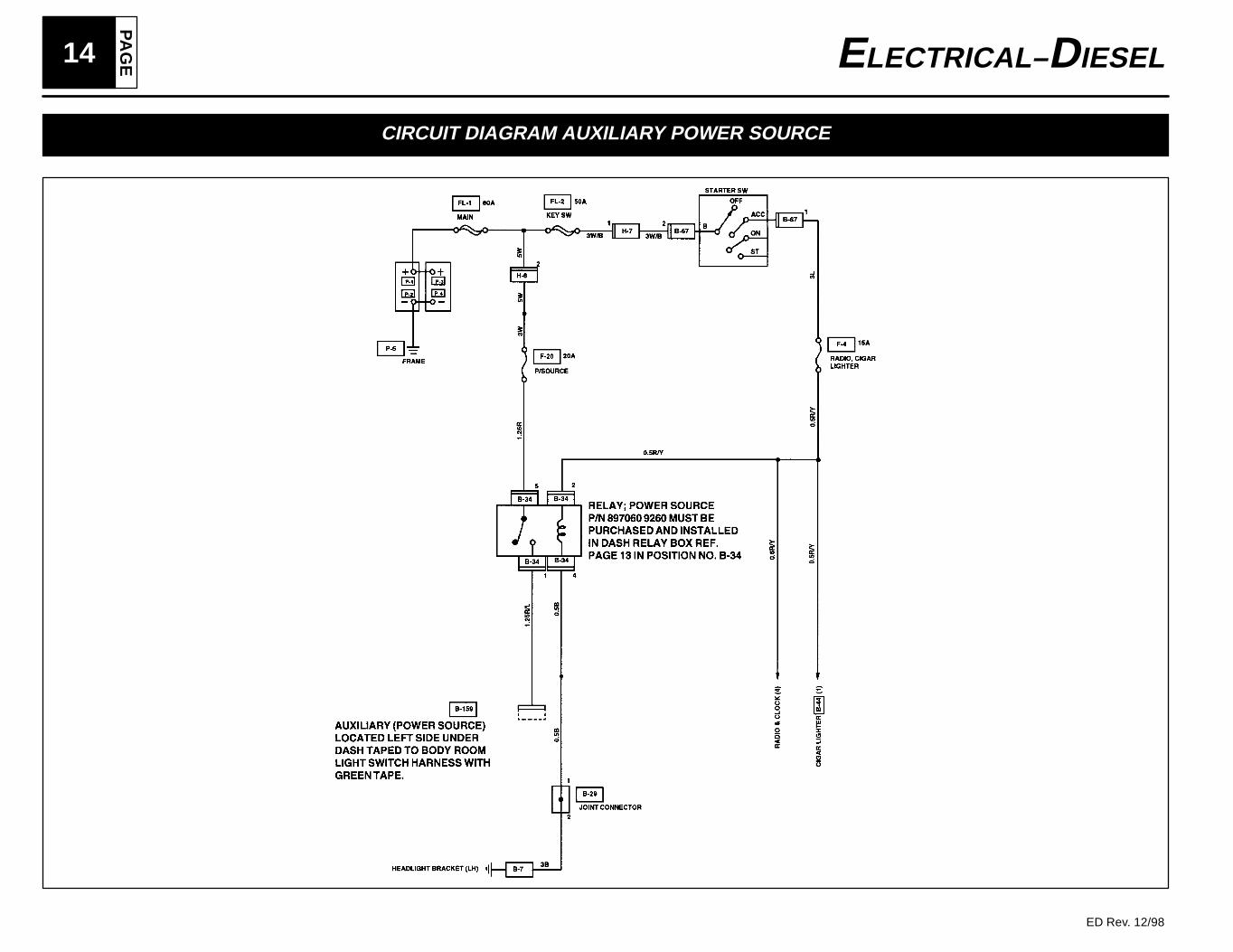
CIRCUIT DIAGRAM AUXILIARY POWER SOURCE
PA
GE
15ELECTRICAL– DIESEL
ED Rev. 12/98
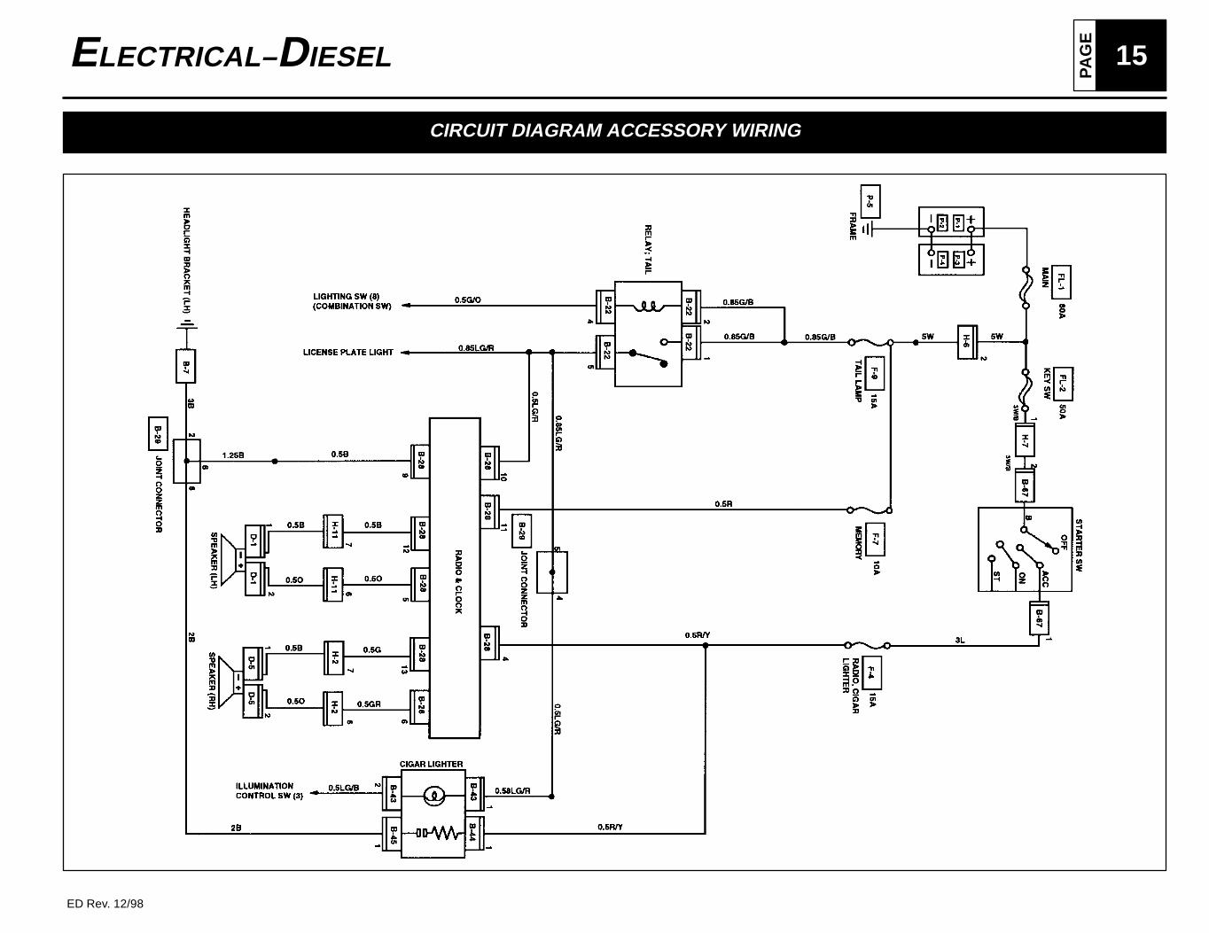
CIRCUIT DIAGRAM ACCESSORY WIRING
PA
GE16 ELECTRICAL– DIESEL
ED Rev. 12/98
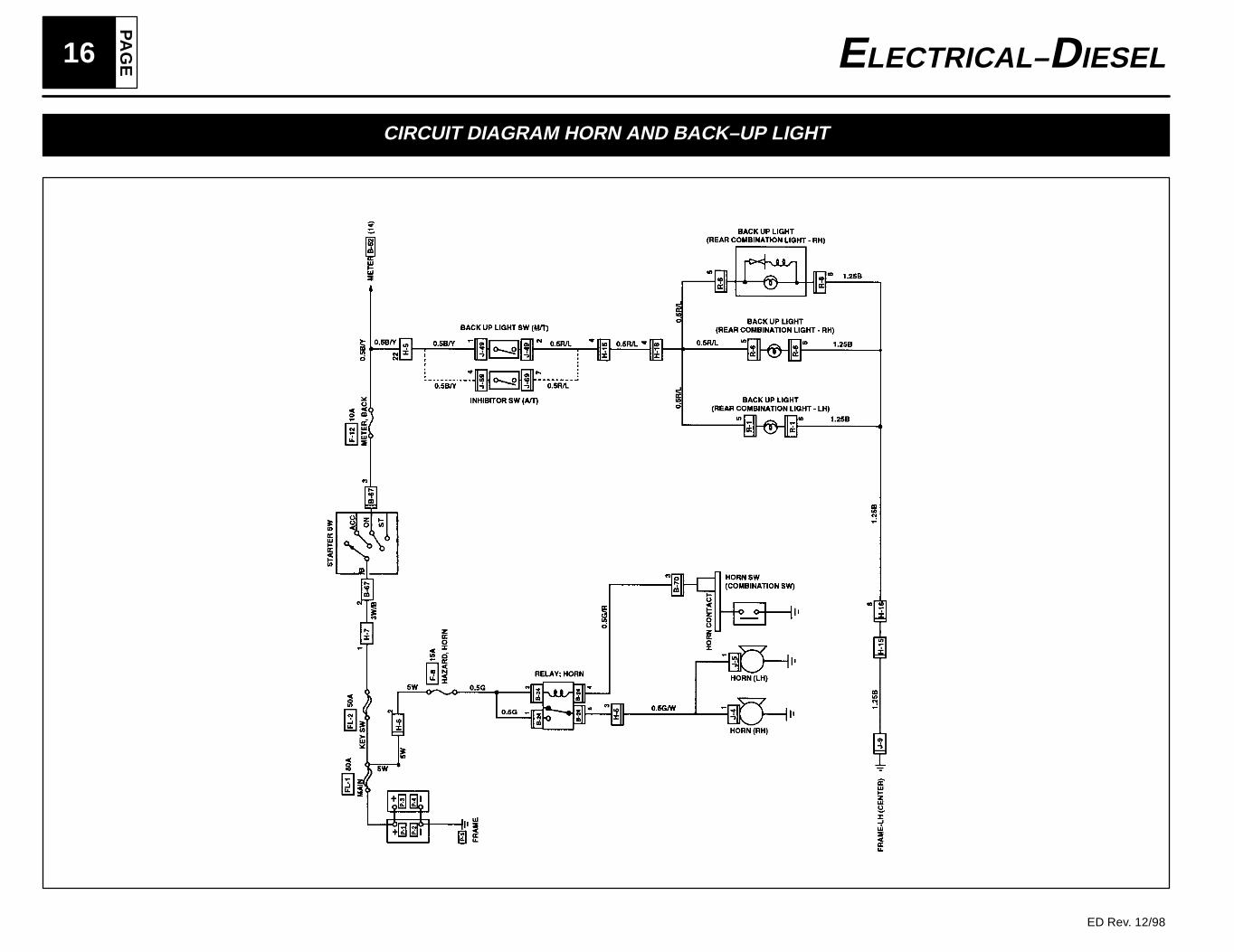
CIRCUIT DIAGRAM HORN AND BACK–UP LIGHT
PA
GE
17ELECTRICAL– DIESEL
ED Rev. 12/98
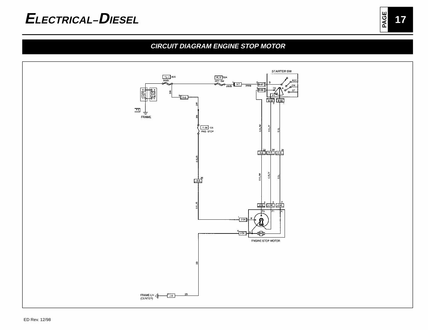
CIRCUIT DIAGRAM ENGINE STOP MOTOR
PA
GE18 ELECTRICAL– DIESEL
ED Rev. 12/98
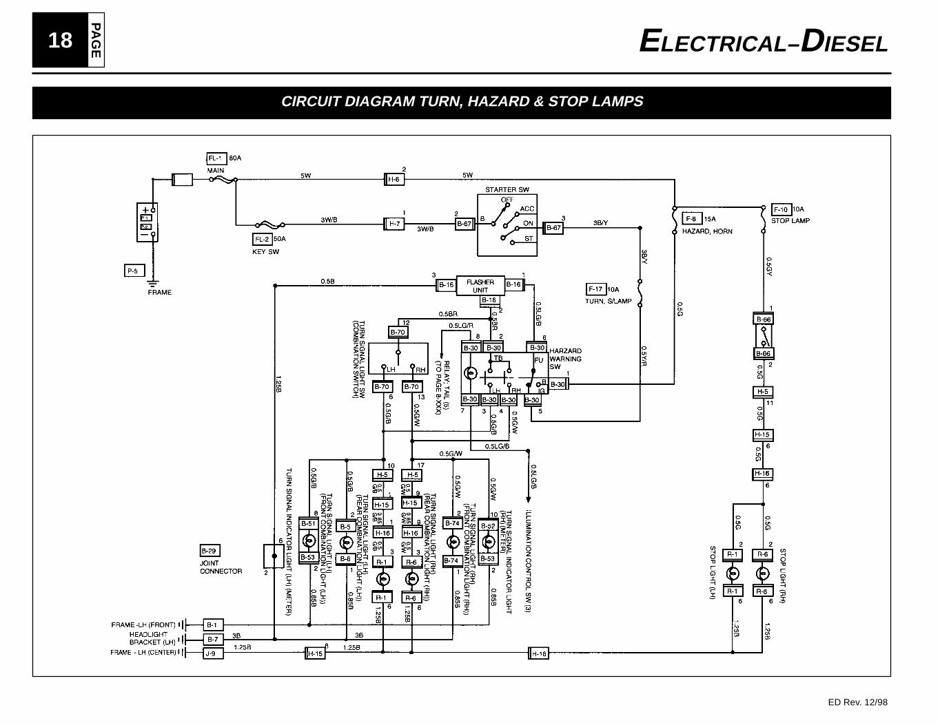
CIRCUIT DIAGRAM TURN, HAZARD & STOP LAMPS
PA
GE
19ELECTRICAL– DIESEL
ED Rev. 12/98
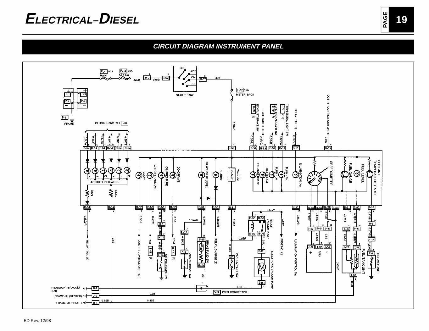
CIRCUIT DIAGRAM INSTRUMENT PANEL
PA
GE20 ELECTRICAL– DIESEL
ED Rev. 12/98
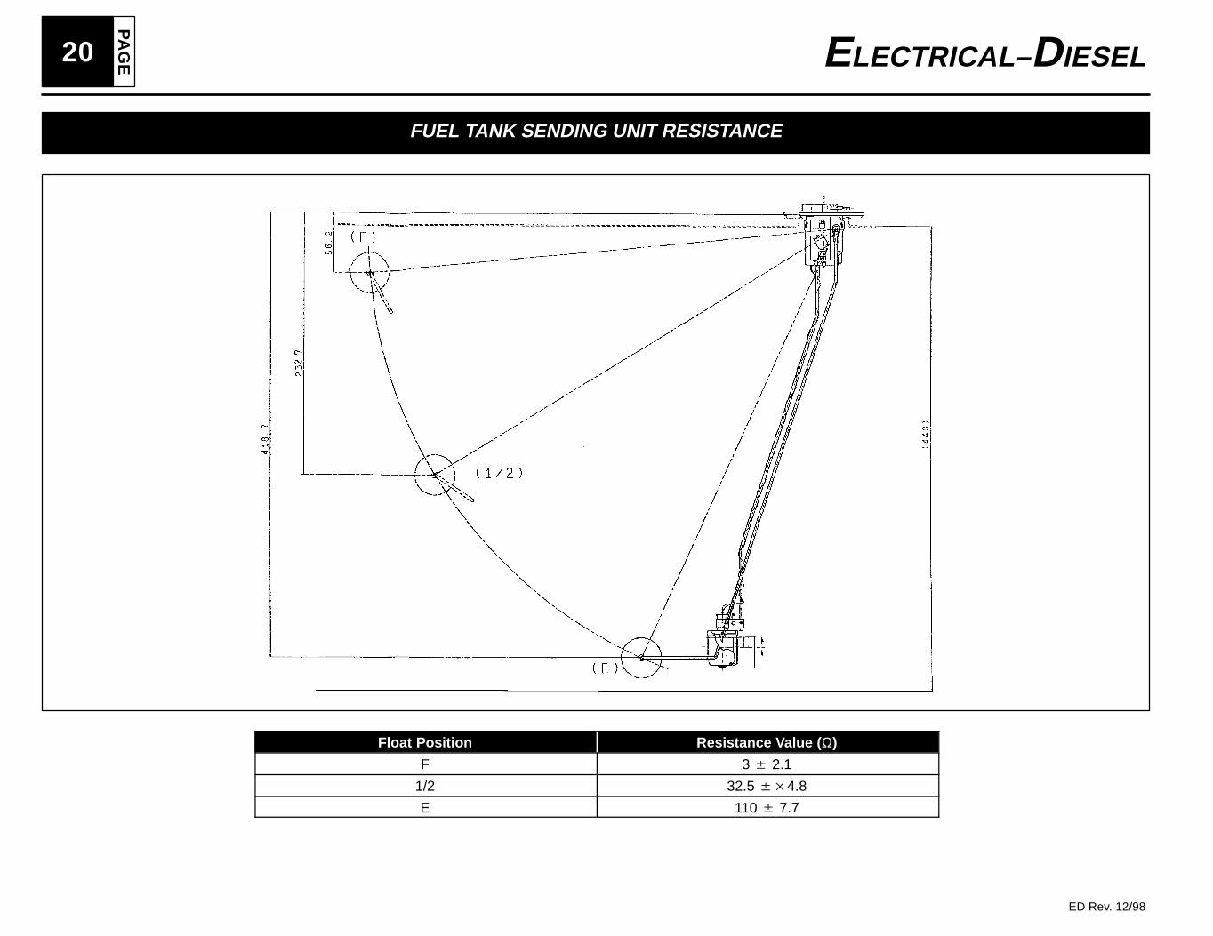
FUEL TANK SENDING UNIT RESISTANCE
Float Position Resistance Value ( Ω)
F 3 2.1
1/2 32.5 4.8
E 110 7.7