Embed Size (px)
Citation preview

ACS800
Hardware ManualDrive Module Trolley for ACS800-04, ACS800-U4, ACS800-04M with option +H354 and ACS800-07


Drive Module Trolley forACS800-04, ACS800-U4,
and ACS800-04M with option +H354
Hardware Manual
3AFE68481562 BEN
EFFECTIVE: 12.05.2005
2005 ABB Oy. All Rights Reserved.


5
General
What this manual containsThis manual:� gives information on compatibility and intended use of the drive module trolley� instructs in safety� shows an overall view of the trolley� instructs in adjusting the trolley for a drive module� instructs in how to remove a drive module of frame size R7 from the cabinet using
the trolley.
CompatibilityThe drive module trolley is compatible with:� ACS800-04 module sizes R7 and R8� ACS800-U4 module sizes R7 and R8� ACS800-04M module sizes R7 and R8 equipped with option +H354 [pedestal
with output on the long side (bookshelf)]� ACS800-07 equipped with module R7 or R8.
Intended useThe trolley helps in removing heavy drive modules of frame sizes R7 and R8 from a cabinet and replacing them. The trolley can be used for installations where the module stands on a pedestal on the bottom of the cabinet, the short side of the module facing the door of the cabinet. The height of the trolley can be adjusted in the range of 161 � 237 mm above the floor level. (Consider that when in use, the upper plane must align with the upper edge of the drive module pedestal.)
Safety
Warning! Ignoring the following instructions can cause physical injury or death, or damage to the equipment.
Do not tilt the drive module. The unit will overturn from a tilt of about 6 degrees. Do not use the trolley on an inclined plane.
Do not use the trolley for long transfer.
Read and follow the safety instructions in ACS800-04/U4/04M Hardware Manual [3AFE64671006 (English)].
General

6
General

7
Hardware description and installation
What this chapter containsThis chapter � shows an overall view of the trolley� instructs in adjusting the trolley for a drive module� instructs in how to remove a drive module of frame size R7 from the cabinet using
the trolley.
Hardware description
1. Base (including wheels) 5. Screws for height adjustment and for fastening skeleton to side plates of base. Three on both sides.2. Skeleton
3. Rails 6. Catch
4. Rail guides 7. Guide tabs for the drive module pedestal8. Drive module support plate
Trolley adjusted for drive module R7 Trolley adjusted for drive module R8
1
2
1
2
3
5
88
5
66
4 4
4
7
7
7
34
7
Hardware description and installation

8
Adjusting the trolley for the drive module size� Tools needed: 17 and 10 mm spanners, head and wrench for torx T20 screws.
� Remove the height adjustment screws � three on both sides � and lift the skeleton off from the base. (See the drawings on page 7.)
� Position the side plates of the base.
� Adjust the width of the skeleton: remove the four screws, pull/push the skeleton to the right position and replace the screws.
Module R7 setting
Module R8 setting
Module R7 setting
Module R8 setting
Hardware description and installation
9
� Adjust the two rails on the top of the skeleton: For each rail, remove four screws, reposition the rail and replace the screws.
� Adjust the rail guides on the top of the skeleton: For each guide, remove the two screws, position the guide and replace the screws.
� Fasten the drive module support plate onto the top plane of the skeleton. Fasten the plate that is not in use onto the base (below the support in use).
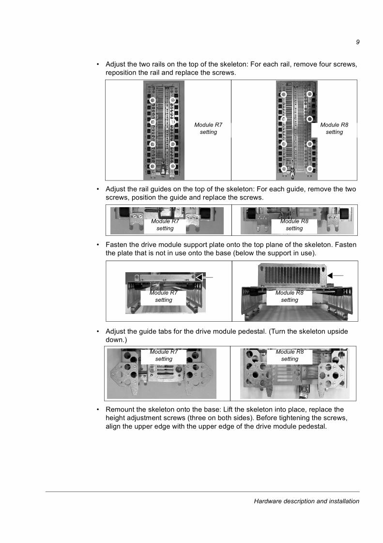
� Adjust the guide tabs for the drive module pedestal. (Turn the skeleton upside down.)
� Remount the skeleton onto the base: Lift the skeleton into place, replace the height adjustment screws (three on both sides). Before tightening the screws, align the upper edge with the upper edge of the drive module pedestal.
Module R7 setting
Module R8 setting
Module R7 setting
Module R8 setting
Module R7 setting
Module R8 setting
Module R7 setting
Module R8 setting
Hardware description and installation

10
Removing a drive module of frame size R7 from the cabinetWARNING! Ignoring the following instruction can cause physical injury or death, or damage to the equipment.
Switch off the input power and wait for 5 min. to let the intermediate circuit capacitors discharge. Disconnect the drive and lock the disconnector to the open position. Ensure by measuring that the drive is dead.
Use extreme caution when manoeuvring the drive module. The module is heavy and has a high centre of gravity. It topples over easily if handled carelessly.
Photo A � Drive cabinet
Remove the plastic shroud(s) above the drive module (1).
Disconnect the control panel cable from the panel mounting platform (2) and remove the cable from the cable sleeve on the horizontal air baffle (3).
Remove the horizontal air baffle (3).
Remove the vertical air baffles (4) on both sides of the drive module.
Remove the front cover of the drive module (5).
Photos B and C � Drive module connections (cover removed)
Disconnect the three input busbars of the drive module (6) from the cabinet busbars.
Unplug the control board (RMIO) power supply cable (7) from the drive module.
Disconnect the fibre optic cables (8) coming from the control board (RMIO) and pull the cables carefully out of the drive module.
Wrap the control panel cable and RMIO board power supply and fibre optic cables together loosely and attach them to upper part of the cubicle.
Remove the L-shaped brackets connecting the drive module to the pedestal (9).
Photos D and E � Drive module fixing screws
Remove the three screws connecting the output busbars of the drive module to the busbars of the drive module pedestal (10).
Remove the two screws fastening the drive module to the back mounting plate of the cabinet (11).
Photo F � Trolley mounted to the drive module pedestal
Adjust the trolley according to the drive module frame size. See section Adjusting the trolley for the drive module size above.
Adjust the height of the trolley using the six screws on the sides (12). Align the upper edge with the upper edge of the drive module pedestal.
Push the trolley against the drive module pedestal so that the two guide tabs of the trolley match the guide holes in the pedestal. Lock the trolley to the pedestal with the catch (13).
Photo G � Drive module on the trolley
Pull the module outwards of the cabinet until it hits the back support plate (14) of the trolley.
Fasten the module to the back support plate using the two screws (15) which were removed from the L-shaped brackets of the module.
Unlock the catch of the trolley. Move the module.
Hardware description and installation

11
Photos D and E
1
6
2
3
4
5
7
8
9
11
12
13
15
Photos B and C
Photo F Photo G
Photo A
10
14
Hardware description and installation

12
Hardware description and installation
13
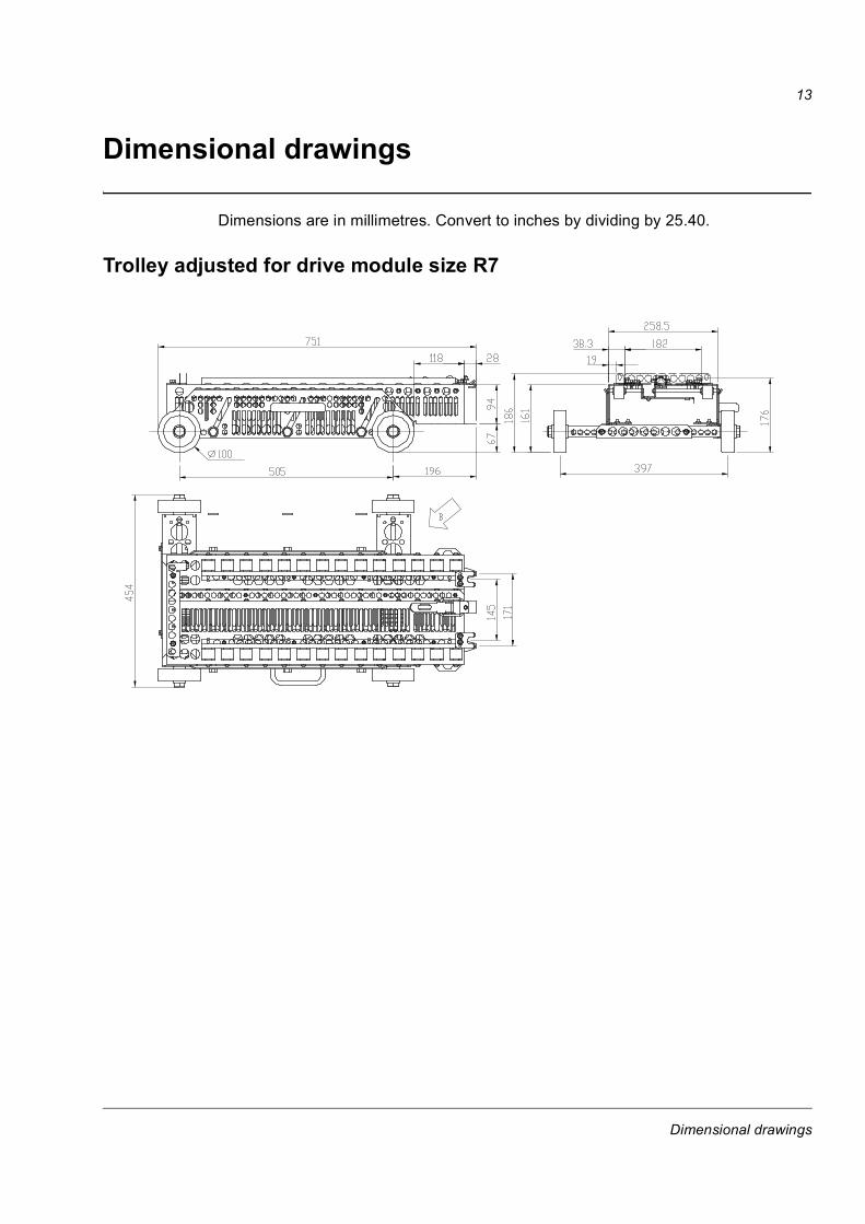
Dimensional drawings
Dimensions are in millimetres. Convert to inches by dividing by 25.40.
Trolley adjusted for drive module size R7
Dimensional drawings

14
Trolley adjusted for drive module size R8
Dimensional drawings


3AFE
6848
1562
B /
ENE
FFE
CTI
VE: 1
2.05
.200
5
ABB OyAC DrivesP.O. Box 184FI-00381 HELSINKIFINLANDTelephone +358 10 22 11Fax +358 10 22 22681Internet http://www.abb.com
ABB Inc.Automation TechnologiesDrives & Motors16250 West Glendale DriveNew Berlin, WI 53151USATelephone 262 785-3200
800-HELP-365Fax 262 780-5135