Embed Size (px)
Citation preview

ENABLING TECHNOLOGIES FOR HIGH FIDELITY SIMULATIONS
Bharat K. Soni, Alan M. Shih, Roy P. Koomullil and Gopalsamy Sankarappan Department of Mechanical Engineering University of Alabama at Birmingham,
Birmingham, AL-35294.
ABSTRACT
The progress realized in the development of enabling technologies that are essential in performing high fidelity computational field simulations is presented. These enabling technologies include geometry-mesh generation and adaptation, visualization and feature detection, virtual reality, parallel and distributed computing, and problem solving environment and framework. The development of toolkits, modular and portable libraries of functions associated with these technologies, will be described. In particular, the Geometry-Grid toolkit (GGTK), MiniCAD system, and Goggle, a visualization and virtual reality framework, will be introduced with complex applications. The application of these functions and toolkits to the development of customized packages for automated analysis and design involving complex geometry is demonstrated. Examples are presented to demonstrate the efficiency, economy, and accuracy of these approaches. The future vision and plan for developing these enabling technologies is presented.
INTRODUCTION
With the simultaneous development of high performance computing and communication (HPCC) and robust and efficient mathematical/numerical algorithms, computational field simulation (CFS) has rapidly emerged as an essential tool for engineering analysis and design. This has fundamentally changed the manner in which the underlying principles of science and engineering are applied to research, design, and development. The current trend is to perform simulations for the purpose of design optimization using interacting multidisciplinary numerical models employing dynamic spatial discretizations.1 These simulations require rapid access to highly accurate predictions for multiple configurations. Often these applications require modeling complex geometric configurations and flexible boundary conditions, multiple integrated computational models (for example, heat conduction, structural deformations, gas dynamics, etc.), as well as automated dynamic spatial discretization. A multitude of flow solvers has been developed to perform these computational simulations. These software packages, which were developed by engineers and scientists in commercial, academic, and government laboratories, have been optimized for distributed/parallel computing environments. In order to meet these requirements efficiently, a closer coupling between the various numerical models and the spatial discretization is essential. This coordination is made even more difficult when massively parallel distributed memory architectures are considered.
14th Annual Thermal & Fluids Analysis Workshop 2003, August 18 -22, 2003, Hampton, Virginia

In the paradigm discussed above, the primary concern is response time. The ultimate goal in an industrial environment is to perform complex grid generation in one hour and the field simulation in one day. Today, with a clean geometry definition in an appropriate format, a structured multiblock grid (for a Navier-Stokes simulation) around complex aircraft can be developed in two to three weeks. On the other hand, an unstructured grid can be developed in a day (for an Euler simulation) and a Cartesian grid can be developed in a matter of hours (for an Euler simulation). The unstructured and Cartesian grid strategies fulfill today's industrial need for Euler simulations. However, as computer power increases and cost per compute cycle decreases, the demand for turbulent Navier-Stokes models with chemical reactions and multi-phase, multi-species flow physics is increasing. Currently, the only reliable simulation technologies that provide these capabilities utilize structured multiblock grids, and the simulation technology for the unstructured and Cartesian grid technologies is still being developed for complex physics. In response to increasing demands, we have established an Enabling Technology Laboratory (ETL) at the University of Alabama at Birmingham (UAB). The ETL addresses research and development associated with enabling technologies which include geometry-mesh generation and adaptation, visualization and feature detection, virtual reality, parallel and distributed computing, and problem solving environment and framework. The progress realized in the development of the enabling technologies essential in performing high fidelity computational field simulations is presented in this paper.
VISION
Figure 1: Geometry-grid generation research vision
Our vision for geometry-grid technology development is presented in Figure 1. The response time chart represents the average time required to perform grid generation, sensitivity analysis (grid generation with minor geometrical-distribution perturbations) and industrial expectations. In general, 80-90 percent of the grid generation labor is spent on the geometry preparation and surface grid generation. In most CFS applications, these surfaces represent solid components and are defined in the CAD/CAM system as a composition of explicit or implicit analytical entities, semi-analytical parametric entities, and/or a sculptured discrete set of points. The
standard common interface for geometry exchange is IGES (International Graphics Exchange Standard), which is based on curve and surface definitions of geometric entities. Unfortunately, these entities are sometimes poorly suited for the treatment of trimmed surfaces that widely appear in industrial CAD definitions.
In the past few years, much effort has been directed toward using CAGD (Computer Aided Geometric Design) techniques and NURBS (Non Uniform Rational B-Splines) for modeling geometrical entities [3]. The NURBS framework provides a common data structure for representing all geometric entities in addition to other desirable properties (shape preserving, local control, convex hull, etc.). The CAD industry, however, is moving in the direction of using solid modeling based geometrical entities. A new international standard, STEP, is under development for solid modeling based on entities. Therefore, the ultimate goal should be to develop grid technology based on solid models.
Enabling technologies in high fidelity computational simulations involve complex geometry and complex physics driven by industrially important engineering problems and applications. It allows the reduction of the man-hours required to perform a particular simulation task. For example, a grid generation about a turbo machine configuration that, in the past, generally required days or weeks of time can be achieved in a matter of hours, even minutes, with today’s commercial tools. This allows the high fidelity simulations to play a significant and meaningful role in the design phase. At ETLab, our research focus on Enabling Technology has been on developing advanced algorithms for geometry manipulation, mesh generation and adaptation technologies for complex geometries, utilizing parallel and distributed computing to facilitate solution of large-scale practical problems. In this paper, we will discuss the approaches and technologies that we have developed at Enabling Technology Laboratory at ME/UAB. The development of toolkits - modular and portable libraries of functions associated with these technologies will be described. In particular, the Geometry-Grid Toolkit (GGTk), MiniCAD system, and Goggle – a visualization and virtual reality framework will be introduced with complex applications. The application of these functions and toolkits to the development of customized packages for automated analysis and design involving complex geometry is demonstrated. Examples are presented to demonstrate the efficiency, economy and accuracy of these approaches. The future vision and plan for the development of these enabling technologies is presented. Detailed description of the numerical geometry, numerical grid generation, and scientific visualization, the three critical enabling technology areas, is provided in the following sections.
NUMERICAL GEOMETRY
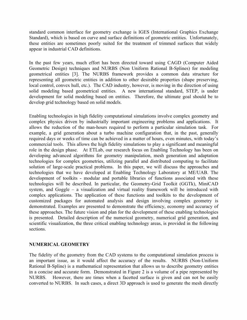
The fidelity of the geometry from the CAD systems to the computational simulation process is an important issue, as it would affect the accuracy of the results. NURBS (Non-Uniform Rational B-Spline) is a mathematical representation that allows us to describe geometry entities in a concise and accurate form. Demonstrated in Figure 2 is a volume of a pipe represented by NURBS. However, there are times when a facetted surface is given and can not be easily converted to NURBS. In such cases, a direct 3D approach is used to generate the mesh directly
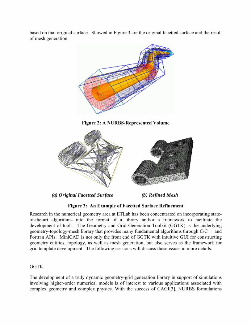
based on that original surface. Showed in Figure 3 are the original facetted surface and the result of mesh generation.
Figure 2: A NURBS-Represented Volume
(a) Original Facetted Surface (b) Refined Mesh
Figure 3: An Example of Facetted Surface Refinement
Research in the numerical geometry area at ETLab has been concentrated on incorporating state-of-the-art algorithms into the format of a library and/or a framework to facilitate the development of tools. The Geometry and Grid Generation Toolkit (GGTK) is the underlying geometry-topology-mesh library that provides many fundamental algorithms through C/C++ and Fortran APIs. MiniCAD is not only the front end of GGTK with intuitive GUI for constructing geometry entities, topology, as well as mesh generation, but also serves as the framework for grid template development. The following sessions will discuss these issues in more details.
GGTK
The development of a truly dynamic geometry-grid generation library in support of simulations involving higher-order numerical models is of interest to various applications associated with complex geometry and complex physics. With the success of CAGI[3], NURBS formulations

were further exploited into a core library format. This geometry-grid toolkit called GGTK is based entirely on NURBS formulations to represent curves, surfaces and volumes. The modules and algorithms could be cast into a library environment and would be accessible from FORTRAN, C, and C++ application programs via APIs. This library contains various algorithms/functionalities for geometry-grid generation and manipulation. GGTK is object-oriented for modularity and allows for scalable parallel operation. It incorporates of existing useful components and is extendable to incorporate emerging technology. It features automated operation, with user intervention and is also user-configurable for compatibility with applications. It interfaces with CAD, solution, and visualization systems and includes a built-in web-based training facility and documentation. Further, it incorporates the following features:
• CAGD functionalities for parametric geometry generation, repair, and modification;
• Cartesian, block-structured, overset, and unstructured tetrahedral, hexahedral, and hybrid/generalized surface and volume mesh generation, manipulation, and exchange/transfer systems;
• Quality assessment, display, and control;
• Tools for addressing changing/deforming/moving geometry and/or mesh;
• Dynamic adaptive coupling with solution systems;
• Interpolation/Approximation of solution properties between distinct grids involving different grid strategies;
• Macros, editing, and script-based operation capability.
It provides salient features such as surface-surface intersection in parametric space (Figure 4). GGTK is used in NSF Information Technology Research Adaptive Software Project to describe the geometry, as well as the geometry description of material flaws (cracks, Figure 5).
Figure 4: Accurate Parametric-Based Surface-Surface Intersection
Figure 5: Geometric Description of a Flaw (Crack) within an Object using NURBS
Representations

MINICAD
MiniCAD provides a graphical front end for GGTK. However, it is not only a demonstrator for GGTK functionalities; it also provides the framework for grid templates. MiniCAD is a geometry design and mesh generation tool with a full graphical user interface (GUI) design based on FLTK (Fast Light Toolkit) and OpenGL, with GGTK as its underlying geometry engine. MiniCAD is capable of constructing or importing geometry entities, and producing watertight topology models. It also allows mesh generation around the models. It provides a user-friendly environment so the user can operate with ease. A view of the MiniCAD interface is shown in Figure 6.
Figure 6: Using MiniCAD to Construct a Pipe Geometry Involving Trimmed Surfaces
Figure 7: Using MiniCAD for Overset Grid Manipulation and Visualization
HOLE PUNCHER
This utility tool was developed specifically for the structure-fluid interaction problem. The cylinder represents the shape of the damaging source. The purpose of this tool is to enable a user to arbitrarily orient the cylinder and remove all the neighboring cells for the computational structure mechanics simulations to analyze the effects of such damages.
Figure 8: Hole Punching Capability for Simulating Structural Damage to a Generic
Wing
Figure 9: Hole Punching Capability for Simulating Structural Damage to a
Multiple-Component Object

NUMERICAL GRID GENERATION
Grid generation can involve various types of topology, such as structured, unstructured, hybrid and generalized grid, and the quality of the grid can be an important factor to the stability and accuracy of the simulations. In this section, we will discuss the differences of grid topologies that are utilized in our software tools, grid adaptation approaches that are being used for improving the accuracy and details of the results, and grid template approaches that can facilitate the simulations for parametric design study.
GRID TOPOLOGIES
There are several categories of grid topologies commonly used in computational engineering- structured grids, unstructured grids, hybrid grids, and generalized grids. Not all of the computational engineering software can accept all four types of grids. The following figures demonstrate each grid topology [5, 6, 7, 12, 14, 15].
Figure 10: Structured, Unstructured, Hybrid, and Generalized Grid Topologies (Generalized Grid Image Courtesy of Dr. David Thompson, Miss. State University)
Table 1. Comparisons of Different Mesh Topologies
We have recently developed mesh generation algorithms for what we term “generalized meshes”[16,17] that contain arbitrary polyhedral elements. Incorporating techniques from structured grid generation and unstructured mesh generation, we have employed edge insertion, edge collapse, and cell combination strategies based on mesh geometry sensors to produce a nearly isotropic surface mesh as one of the boundaries for the tetrahedral mesh. If a quadrilateral surface mesh is used, the resulting volume mesh can be characterized as hexahedral-dominant. We have demonstrated this technology for near-body meshes in two and three dimensions (for surface meshes of arbitrary topology) and for full grids in two dimensions. The cell combination strategy (face deletion) approach has been shown to significantly improve the robustness of the algorithm. We propose to enhance the robustness of hybrid and generalized mesh generation algorithms. We will focus on improving the treatment of front collisions through advanced ray tracing and edge collapse or insertion and cell combination. Additionally, we propose to investigate a posteriori local re-meshing of regions containing arbitrary polyhedra using tetrahedral, pyramidal, and prismatic elements so that the generalized meshes may be used by codes designed for hybrid meshes. The automation and efficiency of the mesh generation process, with a concurrent reduction in response time, and potential for improved solution accuracy are the primary objectives of this effort. Because of the “layered” structure of the generalized mesh, the same types of domain decomposition algorithms used for block-structured grids may be used for generalized meshes. This development is being accomplished in collaboration with MSU. Table 1 illustrates the advantages and disadvantages of these grid topologies in various categories.
GRID ADAPTATION
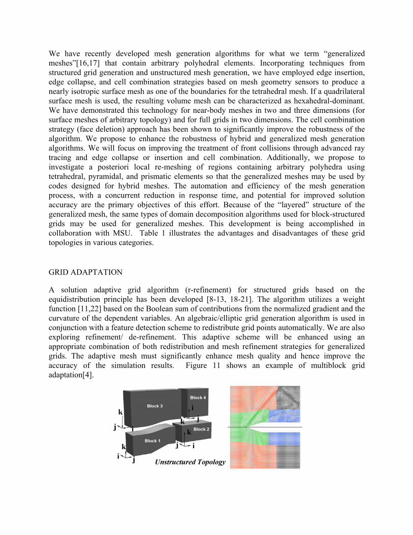
A solution adaptive grid algorithm (r-refinement) for structured grids based on the equidistribution principle has been developed [8-13, 18-21]. The algorithm utilizes a weight function [11,22] based on the Boolean sum of contributions from the normalized gradient and the curvature of the dependent variables. An algebraic/elliptic grid generation algorithm is used in conjunction with a feature detection scheme to redistribute grid points automatically. We are also exploring refinement/ de-refinement. This adaptive scheme will be enhanced using an appropriate combination of both redistribution and mesh refinement strategies for generalized grids. The adaptive mesh must significantly enhance mesh quality and hence improve the accuracy of the simulation results. Figure 11 shows an example of multiblock grid adaptation[4].
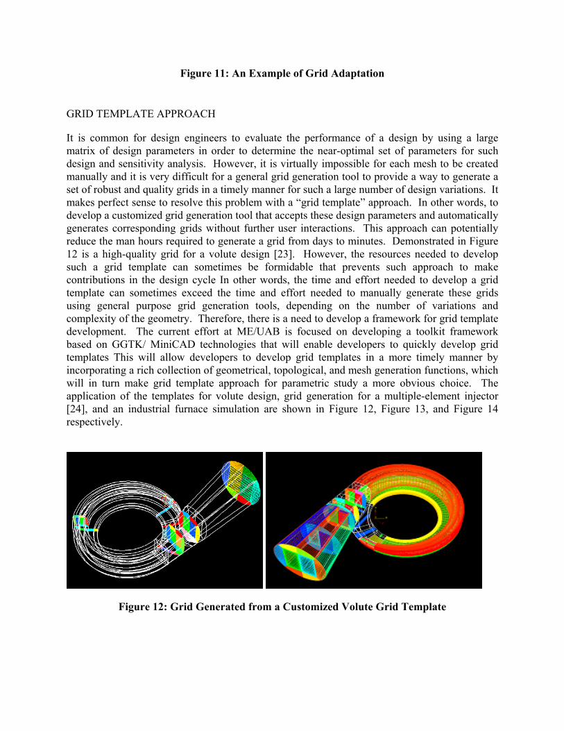
Figure 11: An Example of Grid Adaptation
GRID TEMPLATE APPROACH
It is common for design engineers to evaluate the performance of a design by using a large matrix of design parameters in order to determine the near-optimal set of parameters for such design and sensitivity analysis. However, it is virtually impossible for each mesh to be created manually and it is very difficult for a general grid generation tool to provide a way to generate a set of robust and quality grids in a timely manner for such a large number of design variations. It makes perfect sense to resolve this problem with a “grid template” approach. In other words, to develop a customized grid generation tool that accepts these design parameters and automatically generates corresponding grids without further user interactions. This approach can potentially reduce the man hours required to generate a grid from days to minutes. Demonstrated in Figure 12 is a high-quality grid for a volute design [23]. However, the resources needed to develop such a grid template can sometimes be formidable that prevents such approach to make contributions in the design cycle In other words, the time and effort needed to develop a grid template can sometimes exceed the time and effort needed to manually generate these grids using general purpose grid generation tools, depending on the number of variations and complexity of the geometry. Therefore, there is a need to develop a framework for grid template development. The current effort at ME/UAB is focused on developing a toolkit framework based on GGTK/ MiniCAD technologies that will enable developers to quickly develop grid templates This will allow developers to develop grid templates in a more timely manner by incorporating a rich collection of geometrical, topological, and mesh generation functions, which will in turn make grid template approach for parametric study a more obvious choice. The application of the templates for volute design, grid generation for a multiple-element injector [24], and an industrial furnace simulation are shown in Figure 12, Figure 13, and Figure 14 respectively.
Figure 12: Grid Generated from a Customized Volute Grid Template

Figure 13: Grid Generated from a Customized Multiple-Element Injector Grid Template
(a) Overall geometry (b) Particle Traces from CFD Simulations
Figure 14: Grid Template for an Industrial Furnace.
Our goal is to address the challenges related to performing automatic parametric generation of geometry and multi-block structured and generalized/hybrid meshes tailored for various classes of configurations of interest to industry. The geometry and mesh must be developed as direct analytical and/or semi-analytical functions of the design variables appropriate for the configuration under consideration and must be linked with a CAD/CAM system for further exchange with the design and manufacturing teams. The generation process must be completely automatic (without graphical interaction) and timely enough for meaningful engineering analysis in the design process. The goal is to reduce the response time for geometry-mesh generation from weeks to minutes.
SCIENTIFIC VISUALIZATION
Scientific visualization is an important discipline that enables the users to explore the information contained in massive datasets. Human vision is the most versatile sense in our body. It allows us to perceive a large amount of data with visual queues. With color spectrum and spatial arrangement, geometric information and abstract properties can be overlaid to provide a wealth of meaningful information [25]. Demonstrated in Figure 15 is the visualization of a
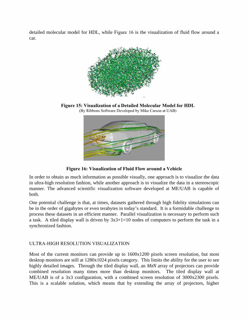
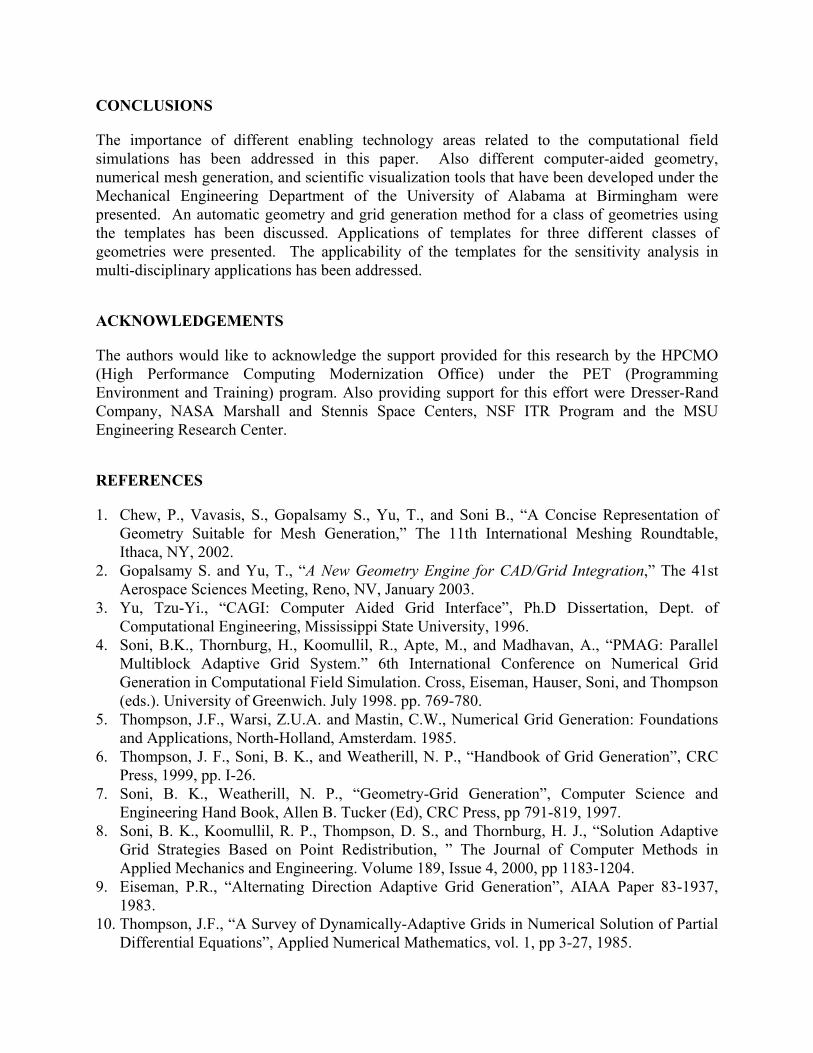
detailed molecular model for HDL, while Figure 16 is the visualization of fluid flow around a car.
Figure 15: Visualization of a Detailed Molecular Model for HDL (By Ribbons Software Developed by Mike Carson at UAB)
Figure 16: Visualization of Fluid Flow around a Vehicle
In order to obtain as much information as possible visually, one approach is to visualize the data in ultra-high resolution fashion, while another approach is to visualize the data in a stereoscopic manner. The advanced scientific visualization software developed at ME/UAB is capable of both.
One potential challenge is that, at times, datasets gathered through high fidelity simulations can be in the order of gigabytes or even terabytes in today’s standard. It is a formidable challenge to process these datasets in an efficient manner. Parallel visualization is necessary to perform such a task. A tiled display wall is driven by 3x3+1=10 nodes of computers to perform the task in a synchronized fashion.
ULTRA-HIGH RESOLUTION VISUALIZATION
Most of the current monitors can provide up to 1600x1200 pixels screen resolution, but most desktop monitors are still at 1280x1024 pixels category. This limits the ability for the user to see highly detailed images. Through the tiled display wall, an MxN array of projectors can provide combined resolution many times more than desktop monitors. The tiled display wall at ME/UAB is of a 3x3 configuration, with a combined screen resolution of 3000x2300 pixels. This is a scalable solution, which means that by extending the array of projectors, higher

resolution can be achieved. Shown in Figure 17 is a frame of a high-resolution animated movie for pollutant transport in City of New Orleans.
Figure 17: High-Resolution (3000x2300 Pixels) Visualization of Pollutant Transport for the City of New Orleans
STEREOSCOPIC VISUALIZATION
Human eyes see an object from slightly different viewing angles, and our brain composes a stereoscopic image of that object. To emulate this using display system, we can either swap the left eye image with the right eye image at a very high refreshing rate with synchronized shutter glasses (active stereo), or we can polarize both images with different polarization angles in combination with polarized glasses to filter out one of the images for each eye (passive stereo). Either approach provides one image for each eye so that our brain would be able to compose the stereoscopic image of that object, as we naturally would. Based on the passive stereoscopic principal, the stereoscopic display system at ME/UAB consists of two LCD projectors with polarized lens, and the software developed at ME/UAB is capable of side-by-side stereo allowing the user to visualize datasets in stereoscopic manner. Figure 18 shows the action.
Figure 18: Passive Stereoscopic Display of a Human Head
CONCLUSIONS
The importance of different enabling technology areas related to the computational field simulations has been addressed in this paper. Also different computer-aided geometry, numerical mesh generation, and scientific visualization tools that have been developed under the Mechanical Engineering Department of the University of Alabama at Birmingham were presented. An automatic geometry and grid generation method for a class of geometries using the templates has been discussed. Applications of templates for three different classes of geometries were presented. The applicability of the templates for the sensitivity analysis in multi-disciplinary applications has been addressed.
ACKNOWLEDGEMENTS
The authors would like to acknowledge the support provided for this research by the HPCMO (High Performance Computing Modernization Office) under the PET (Programming Environment and Training) program. Also providing support for this effort were Dresser-Rand Company, NASA Marshall and Stennis Space Centers, NSF ITR Program and the MSU Engineering Research Center.
REFERENCES
1. Chew, P., Vavasis, S., Gopalsamy S., Yu, T., and Soni B., “A Concise Representation of Geometry Suitable for Mesh Generation,” The 11th International Meshing Roundtable, Ithaca, NY, 2002.
2. Gopalsamy S. and Yu, T., “A New Geometry Engine for CAD/Grid Integration,” The 41st Aerospace Sciences Meeting, Reno, NV, January 2003.
3. Yu, Tzu-Yi., “CAGI: Computer Aided Grid Interface”, Ph.D Dissertation, Dept. of Computational Engineering, Mississippi State University, 1996.
4. Soni, B.K., Thornburg, H., Koomullil, R., Apte, M., and Madhavan, A., “PMAG: Parallel Multiblock Adaptive Grid System.” 6th International Conference on Numerical Grid Generation in Computational Field Simulation. Cross, Eiseman, Hauser, Soni, and Thompson (eds.). University of Greenwich. July 1998. pp. 769-780.
5. Thompson, J.F., Warsi, Z.U.A. and Mastin, C.W., Numerical Grid Generation: Foundations and Applications, North-Holland, Amsterdam. 1985.
6. Thompson, J. F., Soni, B. K., and Weatherill, N. P., “Handbook of Grid Generation”, CRC Press, 1999, pp. I-26.
7. Soni, B. K., Weatherill, N. P., “Geometry-Grid Generation”, Computer Science and Engineering Hand Book, Allen B. Tucker (Ed), CRC Press, pp 791-819, 1997.
8. Soni, B. K., Koomullil, R. P., Thompson, D. S., and Thornburg, H. J., “Solution Adaptive Grid Strategies Based on Point Redistribution, ” The Journal of Computer Methods in Applied Mechanics and Engineering. Volume 189, Issue 4, 2000, pp 1183-1204.
9. Eiseman, P.R., “Alternating Direction Adaptive Grid Generation”, AIAA Paper 83-1937, 1983.
10. Thompson, J.F., “A Survey of Dynamically-Adaptive Grids in Numerical Solution of Partial Differential Equations”, Applied Numerical Mathematics, vol. 1, pp 3-27, 1985.

11. Thornburg, H.J. and Soni, B.K., “Weight Functions inGrid Adaption, ” Proceedings of the 4th International Conference in Numerical Grid Generation in Computational Fluid Dynamics and Related Fields held at Swansea, Wales 6-8th April 1994.
12. Soni, B.K., “Structured Grid Generation in Computational Fluid Dynamics, ” Vichnevetsky, R., Knight, D., and Richter, G. (eds.), Advances in Computer Methods for Partial Differential Equations VII, Rutgers University, pp 689-695, June 1992.
13. Niederdrenk, P., “Solution Adaptive Grid Generation by Hyperbolic/Parabolized P.D.E.s, ” Numerical Grid Generation in Computational Fluid Dynamics and Related Fields, Eds. A. S.-Arcilla, J. Hauser, P. R. Eiseman, and J. F. Thompson, Elsevier Science Publishing Company, New York, 1991.
14. Koomullil, R., Soni, B., and Huang, C-T., “Navier-Stokes Simulation on Hybrid Grids.” AIAA-96-0767. 34th Aerospace Sciences Meeting & Exhibit. January 15-18, 1996. Reno, NV.
15. Koomullil, R. P., and Soni, B. K., “Flow Simulation Using Generalized Static and Dynamics Grids, ” AIAA Journal, Volume 37, Number 12, Dec. 1999, pp 1551-1557.
16. Thompson, D. S., and Soni, B. K., “Generation of Quad- and Hex-Dominant, Semistructured Meshes Using an Advancing Layer Scheme.” Proceedings of the 8th International Meshing Roundtable, October 1999.
17. Thompson, D. S., and Soni, B. K., “Semistructured Grid Generation in Three-Dimensions using a Parabolic Marching Scheme”, AIAA Paper 2000-1004, AIAA 38th Aerospace Sciences Meeting, Reno, NV, January 2000.
18. Anderson, D. A., “Adaptive Grid Methods for Partial Differential Equations, ” Advances in Grid Generation, ASME Publication, New York, pp. 1-15, 1983.
19. Soni, B.K. and Yang, J.C., “General Purpose Adaptive Grid Generation System, ” AIAA-92-0664, 30th Aerospace Sciences Meeting, Reno, NV, Jan. 6-9, 1992.
20. Soni, B.K., Weatherill, N.P. and Thompson, J.F., “Grid Adaptive Strategies in CFD, ” International Conference on Hydo Science and Engineering, Washington, D.C., June 7-11, 1993.
21. Dwyer, H.A., “Grid Adaption for Problems in Fluid Dynamics, ” AIAA Journal, vol. 22. No. 12, pp. 1705-1712, December 1984.
22. Thornburg, H.J. and Soni, B.K., “Weight Functions inGrid Adaption, ” Proceedings of the 4th International Conference in Numerical Grid Generation in Computational Fluid Dynamics and Related Fields held at Swansea, Wales 6-8th April 1994.
23. Soni, B. K., Hur, JiYoung, and Collins, E. M., “Parametric Grid Generation Applicable to Design Optimization of Centrifugal Compressor Configurations, ” AIAA-2000-4862, 8th
AIAA/NASA/USAF/ISSMO Symposium on Multidisciplinary Analysis and Optimization, Sept. 6-8 2000, Long Beach, CA.
24. Jeong, H, Koomullil, R., Shih, A., and Soni, B., “Toward Enabling Objective Engineering Designs for Rocket Injectors-Efficient Evaluation of Larger Design Space Via Automated Parametric Grid Generation,” AIAA Paper 2003-5058, The 39th Joint Propulsion Conference and Exhibit, Huntsville, Alabama, 20-23 July 2003.
25. Stein, R., Shih, A.M., Baker, M.P., Cerco, C.F., Noel, M.R.,"Scientific Visualization of Water Quality in the Chesapeake Bay," IEEE Visualization 2000, October 8 - October 13, 2000, Salt Lake City, Utah, USA

CONTACTS
Professor Bharat K. Soni ([email protected]) is the chairman of Department of Mechanical Engineering at UAB.
Dr. Alan M. Shih ([email protected]) is a research associate professor at the Department of Mechanical Engineering at UAB. He is the leader of Enabling Technology Laboratory at ME/UAB.
Dr. Roy P. Koomullil ([email protected]) is an assistant professor at the Department of Mechanical Engineering at UAB.