Embed Size (px)
Citation preview
Enabling Enhanced Mobile Broadband by mm-Waves and the Road to 5G V2X
Dr. Taro Eichler
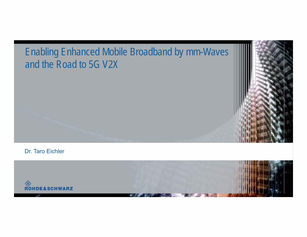
Enhanced Mobile Broadband (eMBB)Technical Challenges
eMBB
ı 100 MHz bandwidth at < 6 GHz ı 800 … 2 GHz bandwidth at > 6 GHzı mmWave frequencies (candidate bands: ~28 GHz, ~39 GHz, ~70 GHz)
especially for high data rate applicationsı Highly directional transmission is needed to compensate severe path loss
(beamforming used at Tx and Rx), Dynamic beam adaptation is essential
ı Research on new channel models
ı New 5G signal waveform for high bandwidth operation at mmWave
ı “Over-The-Air“ (OTA) instead ot conducted measurements; up to 1024 Tx/Rx antenna elements
ı Bandwidth and waveform type have impact on 5G capable components (PAs, filters, D/A, A/D…)
BW
WV
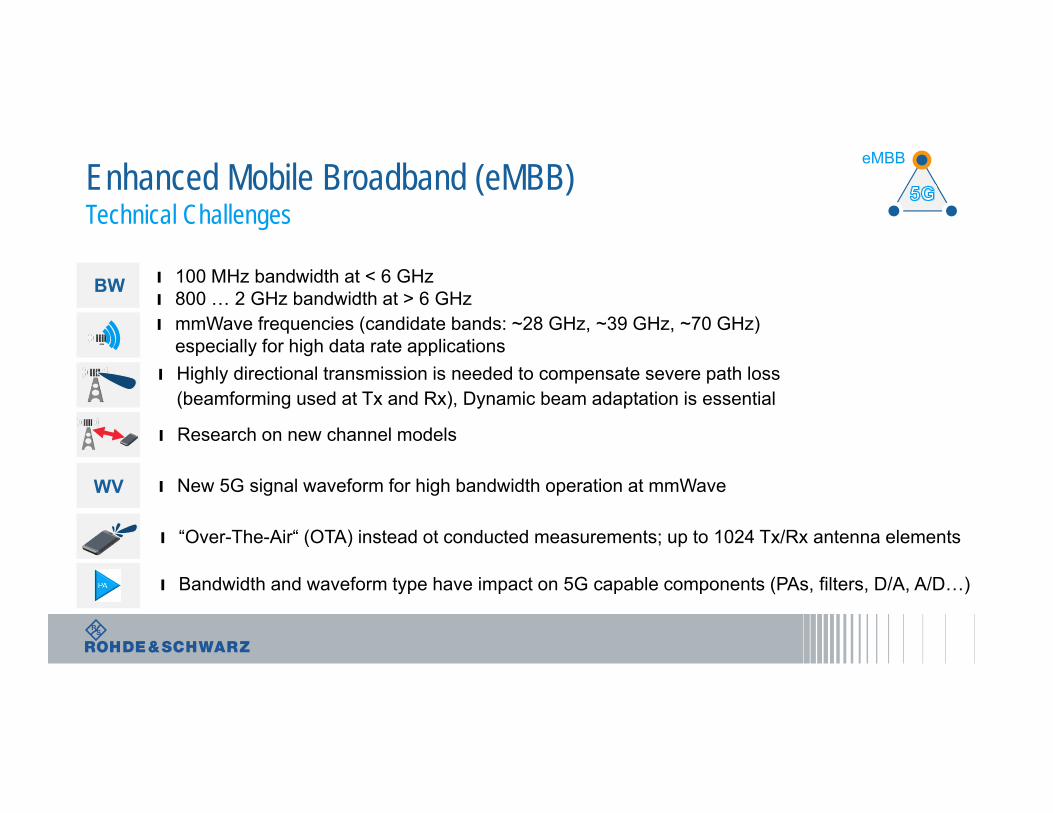
ı Considered frequency ranges and bands for 5G at cm- and mm-Waves: 24.25 to 27.5 GHz 31.8 to 33.4 GHz 37.0 to 43.5 GHz 45.4 to 50.2 GHz 50.4 to 52.6 GHz 66 to 76 GHz 81 to 86 GHz.
27.5 to 29.5 GHz band is not listed, but is still expected to play an important role for anticipated 5G deployments.
Conclusion from WRC-15 related to 5G frequency candidatesSub-6GHz mmWave: 30-90 GHzcmWave: 10-20 GHz
CoverageMobilityReliability
High CapacityMassive Throughput
Ultra-Dense Networks
n x 20 MHz n x 100 MHz 1-2 GHzCarrier BW
Macro Small Ultra-small
Multi-Carrier (OFDM) Multi-Carrier (OFDM) Multi-Crrier? Single Carrier?
Cell Size
Waveform
Recommended Bands < 6GHz (Europe)
Sub 700MHz470-694 MHz
L-Band1350-1400 MHz1427-1517 MHz
TD-LTE2.7-2.9 GHz
C-Band3.4-3.8 GHz3.8-4.2 GHz
Total available bandwidth: 1.3 GHz
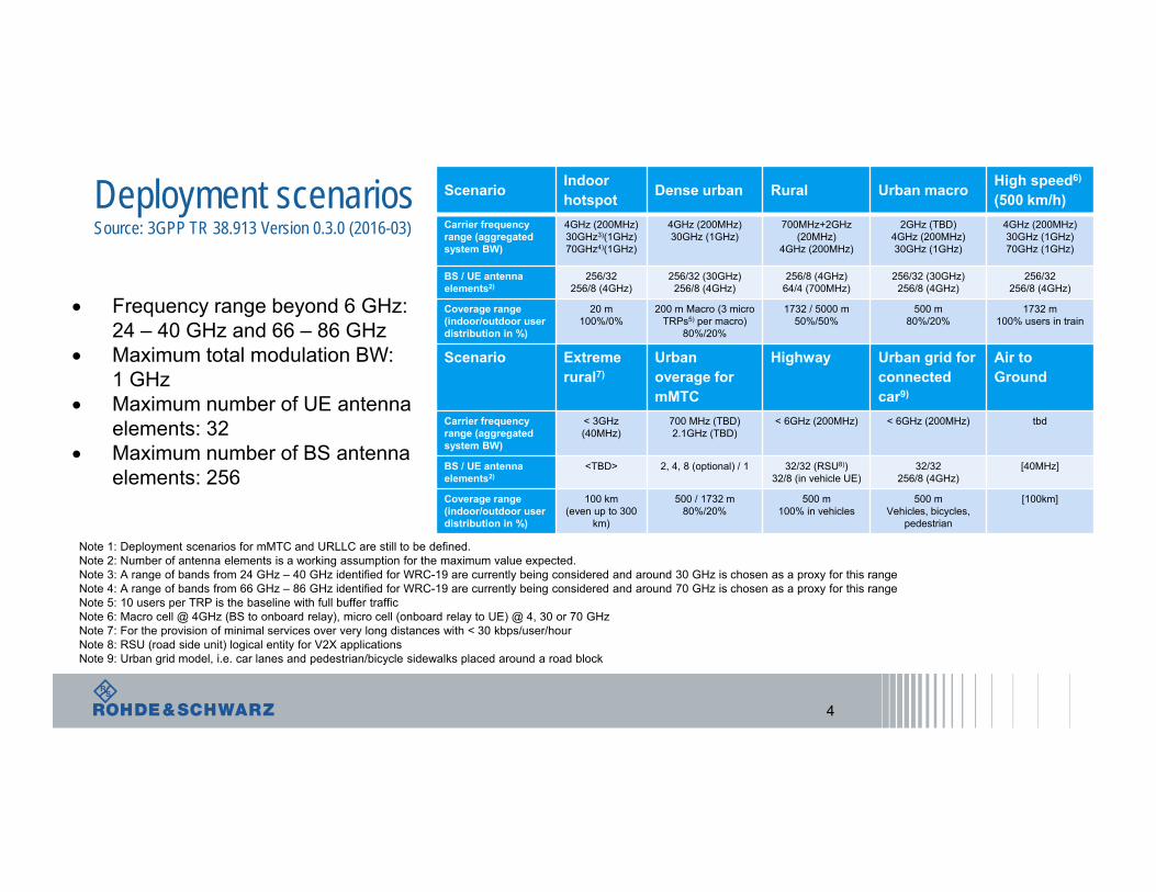
Deployment scenariosSource: 3GPP TR 38.913 Version 0.3.0 (2016-03)
4
Scenario Indoorhotspot Dense urban Rural Urban macro High speed6)
(500 km/h)Carrier frequency range (aggregated system BW)
4GHz (200MHz)30GHz3)(1GHz)70GHz4)(1GHz)
4GHz (200MHz)30GHz (1GHz)
700MHz+2GHz (20MHz)
4GHz (200MHz)
2GHz (TBD)4GHz (200MHz)30GHz (1GHz)
4GHz (200MHz)30GHz (1GHz)70GHz (1GHz)
BS / UE antenna elements2)
256/32 256/8 (4GHz)
256/32 (30GHz)256/8 (4GHz)
256/8 (4GHz)64/4 (700MHz)
256/32 (30GHz) 256/8 (4GHz)
256/32 256/8 (4GHz)
Coverage range(indoor/outdoor user distribution in %)
20 m100%/0%
200 m Macro (3 micro TRPs5) per macro)
80%/20%
1732 / 5000 m50%/50%
500 m80%/20%
1732 m100% users in train
Scenario Extreme rural7)
Urban overage for mMTC
Highway Urban grid for connected car9)
Air to Ground
Carrier frequency range (aggregated system BW)
< 3GHz (40MHz)
700 MHz (TBD)2.1GHz (TBD)
< 6GHz (200MHz) < 6GHz (200MHz) tbd
BS / UE antenna elements2)
<TBD> 2, 4, 8 (optional) / 1 32/32 (RSU8))32/8 (in vehicle UE)
32/32256/8 (4GHz)
[40MHz]
Coverage range(indoor/outdoor user distribution in %)
100 km(even up to 300
km)
500 / 1732 m80%/20%
500 m100% in vehicles
500 mVehicles, bicycles,
pedestrian
[100km]
Note 1: Deployment scenarios for mMTC and URLLC are still to be defined.Note 2: Number of antenna elements is a working assumption for the maximum value expected.Note 3: A range of bands from 24 GHz – 40 GHz identified for WRC-19 are currently being considered and around 30 GHz is chosen as a proxy for this rangeNote 4: A range of bands from 66 GHz – 86 GHz identified for WRC-19 are currently being considered and around 70 GHz is chosen as a proxy for this rangeNote 5: 10 users per TRP is the baseline with full buffer trafficNote 6: Macro cell @ 4GHz (BS to onboard relay), micro cell (onboard relay to UE) @ 4, 30 or 70 GHzNote 7: For the provision of minimal services over very long distances with < 30 kbps/user/hourNote 8: RSU (road side unit) logical entity for V2X applicationsNote 9: Urban grid model, i.e. car lanes and pedestrian/bicycle sidewalks placed around a road block
Frequency range beyond 6 GHz:24 – 40 GHz and 66 – 86 GHz
Maximum total modulation BW:1 GHz
Maximum number of UE antennaelements: 32
Maximum number of BS antenna elements: 256
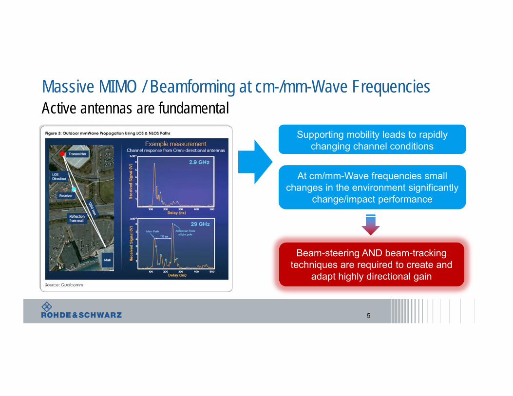
Massive MIMO / Beamforming at cm-/mm-Wave FrequenciesActive antennas are fundamental
5
Supporting mobility leads to rapidly changing channel conditions
At cm/mm-Wave frequencies small changes in the environment significantly
change/impact performance
Beam-steering AND beam-tracking techniques are required to create and
adapt highly directional gain
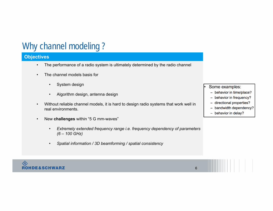
Why channel modeling ?
6
• The performance of a radio system is ultimately determined by the radio channel
• The channel models basis for
• System design
• Algorithm design, antenna design
• Without reliable channel models, it is hard to design radio systems that work well in real environments.
• New challenges within “5 G mm-waves”
• Extremely extended frequency range i.e. frequency dependency of parameters (6 – 100 GHz)
• Spatial information / 3D beamforming / spatial consistency
ObjectivesObjectives
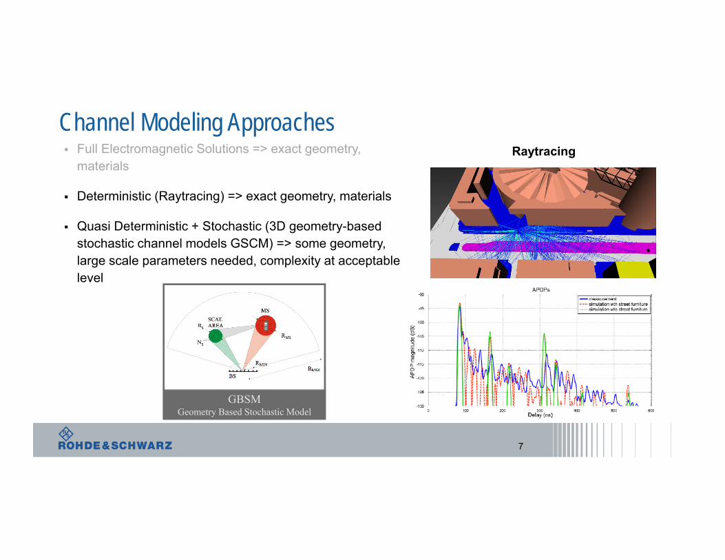
Channel Modeling Approaches
7
Full Electromagnetic Solutions => exact geometry, materials
Deterministic (Raytracing) => exact geometry, materials
Quasi Deterministic + Stochastic (3D geometry-based stochastic channel models GSCM) => some geometry, large scale parameters needed, complexity at acceptable level
Raytracing
GBSMGeometry Based Stochastic Model
1
0
, iL
j ti i
i
h t a t e
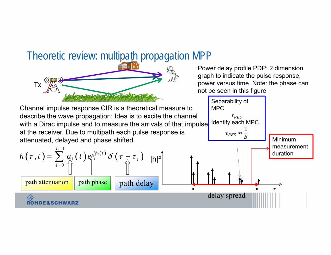
Channel impulse response CIR is a theoretical measure todescribe the wave propagation: Idea is to excite the channelwith a Dirac impulse and to measure the arrivals of that impulseat the receiver. Due to multipath each pulse response is attenuated, delayed and phase shifted.
delay spread
|h|²
Minimummeasurement duration
Separability of MPC
Identify each MPC.1
Tx
path delaypath attenuation path phase
Power delay profile PDP: 2 dimensiongraph to indicate the pulse response, power versus time. Note: the phase can not be seen in this figure
Theoretic review: multipath propagation MPP
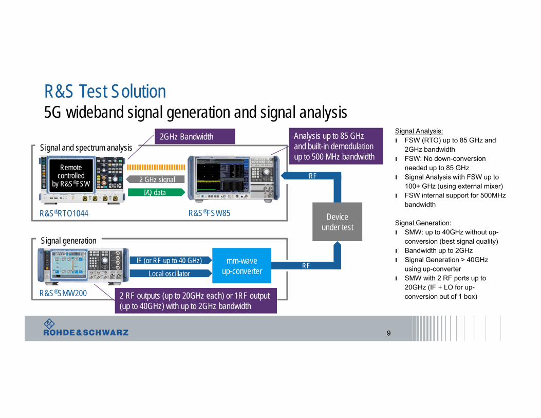
R&S Test Solution5G wideband signal generation and signal analysis
9
RF
Remotecontrolled
by R&S®FSW
R&S®RTO1044 R&S®FSW85
2 GHz signal I/Q data
RF
Device under test
R&S®SMW200
IF (or RF up to 40 GHz) Local oscillator
mm-waveup-converter
Signal and spectrum analysis
Signal generation
Analysis up to 85 GHz and built-in demodulation up to 500 MHz bandwidth
2GHz Bandwidth
2 RF outputs (up to 20GHz each) or 1RF output (up to 40GHz) with up to 2GHz bandwidth
Signal Analysis:ı FSW (RTO) up to 85 GHz and
2GHz bandwidthı FSW: No down-conversion
needed up to 85 GHz ı Signal Analysis with FSW up to
100+ GHz (using external mixer)ı FSW internal support for 500MHz
bandwidth
Signal Generation:ı SMW: up to 40GHz without up-
conversion (best signal quality)ı Bandwidth up to 2GHz ı Signal Generation > 40GHz
using up-converterı SMW with 2 RF ports up to
20GHz (IF + LO for up-conversion out of 1 box)
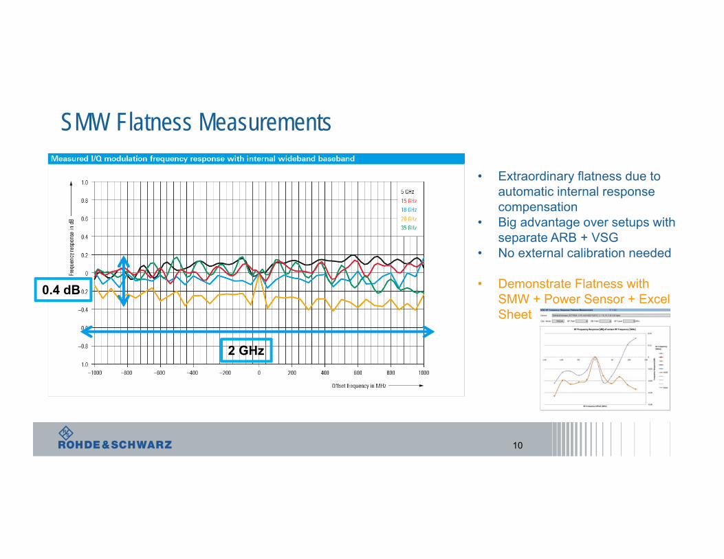
SMW Flatness Measurements
10
0.4 dB
2 GHz
• Extraordinary flatness due toautomatic internal responsecompensation
• Big advantage over setups withseparate ARB + VSG
• No external calibration needed
• Demonstrate Flatness with SMW + Power Sensor + Excel Sheet
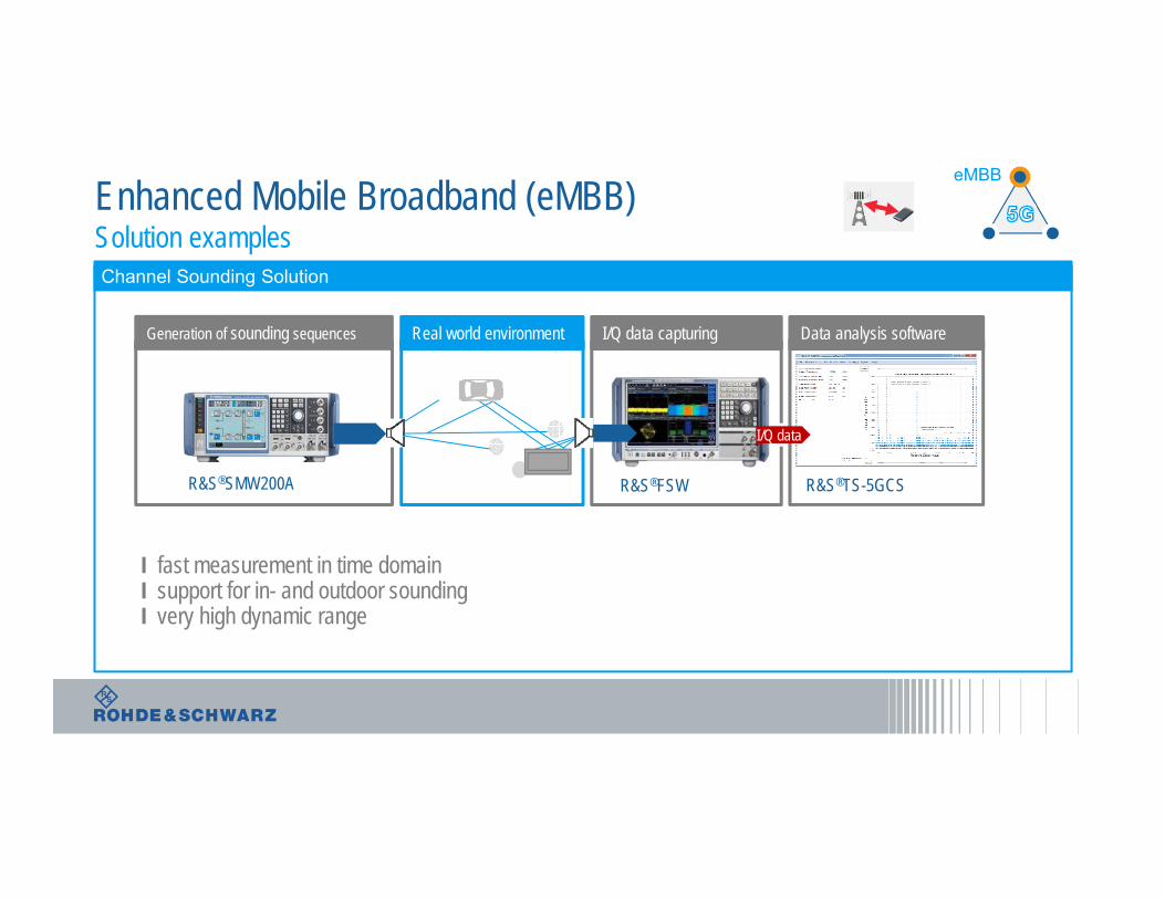
Enhanced Mobile Broadband (eMBB)Solution examples
eMBB
Channel Sounding Solution
Generation of sounding sequences
I/Q data
R&S®FSWR&S®SMW200A
I/Q data capturing Data analysis softwareReal world environment
R&S®TS-5GCS
I fast measurement in time domainI support for in- and outdoor sounding I very high dynamic range
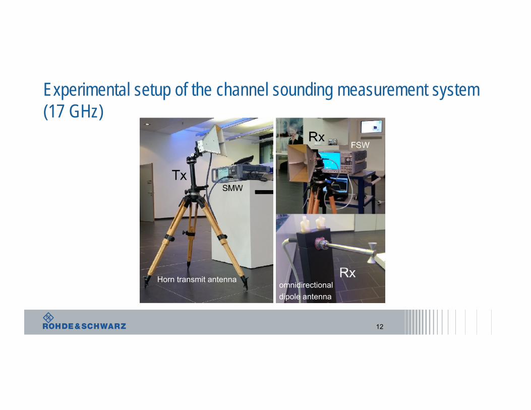
Experimental setup of the channel sounding measurement system (17 GHz)
Horn transmit antennaomnidirectionaldipole antenna
12
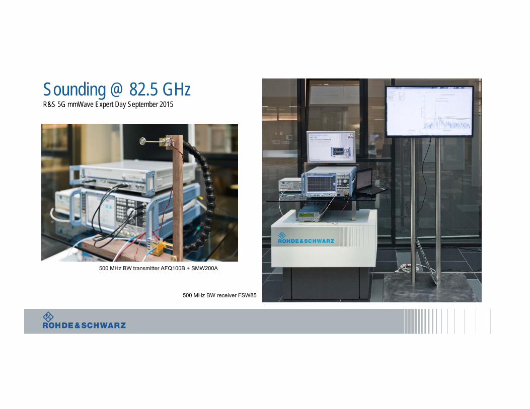
Sounding @ 82.5 GHzR&S 5G mmWave Expert Day September 2015
500 MHz BW transmitter AFQ100B + SMW200A
500 MHz BW receiver FSW85
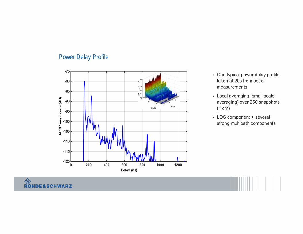
One typical power delay profile taken at 20s from set of measurements
Local averaging (small scale averaging) over 250 snapshots (1 cm)
LOS component + several strong multipath components
Power Delay Profile
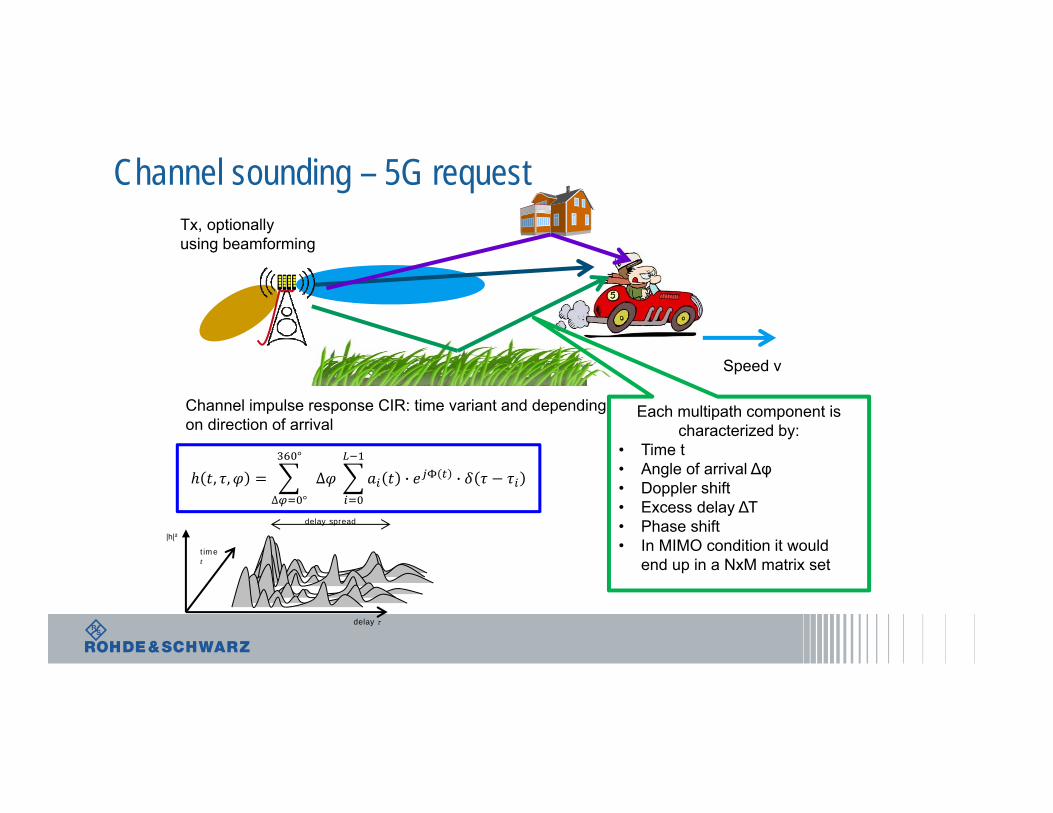
Channel sounding – 5G requestTx, optionallyusing beamforming
Speed v
Each multipath component ischaracterized by:
• Time t• Angle of arrival Δφ• Doppler shift• Excess delay ΔΤ• Phase shift• In MIMO condition it would
end up in a NxM matrix set
Channel impulse response CIR: time variant and dependingon direction of arrival
time t
delay spread
delay
|h|²
, , °
∆ °
∆ · ·
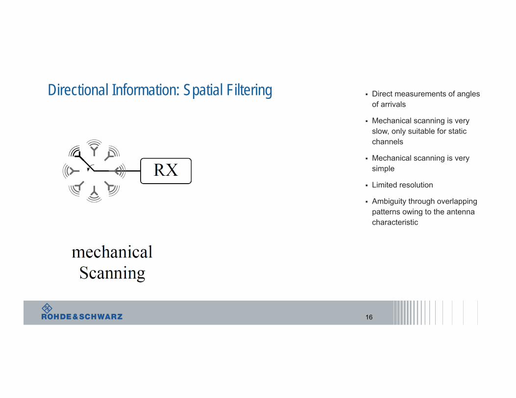
Direct measurements of angles of arrivals
Mechanical scanning is very slow, only suitable for static channels
Mechanical scanning is very simple
Limited resolution
Ambiguity through overlapping patterns owing to the antenna characteristic
Directional Information: Spatial Filtering
16
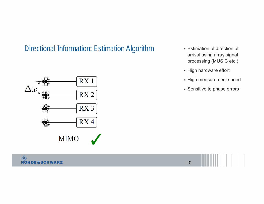
Estimation of direction of arrival using array signal processing (MUSIC etc.)
High hardware effort
High measurement speed
Sensitive to phase errors
Directional Information: Estimation Algorithm
17
✓
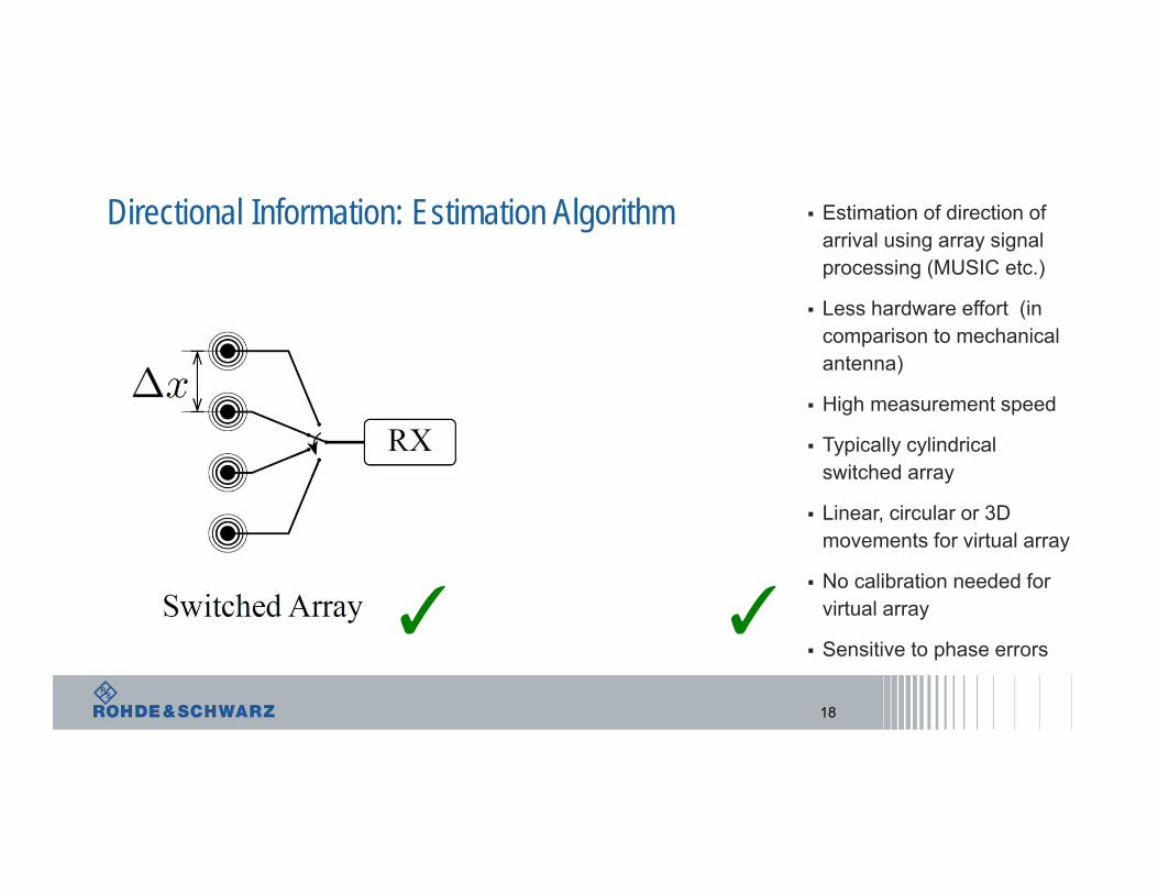
Estimation of direction of arrival using array signal processing (MUSIC etc.)
Less hardware effort (in comparison to mechanical antenna)
High measurement speed
Typically cylindrical switched array
Linear, circular or 3D movements for virtual array
No calibration needed for virtual array
Sensitive to phase errors
Directional Information: Estimation Algorithm
18
✓ ✓
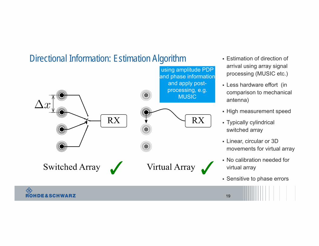
Estimation of direction of arrival using array signal processing (MUSIC etc.)
Less hardware effort (in comparison to mechanical antenna)
High measurement speed
Typically cylindrical switched array
Linear, circular or 3D movements for virtual array
No calibration needed for virtual array
Sensitive to phase errors
Directional Information: Estimation Algorithm
19
✓ ✓
using amplitude PDP and phase information
and apply post-processing, e.g.
MUSIC
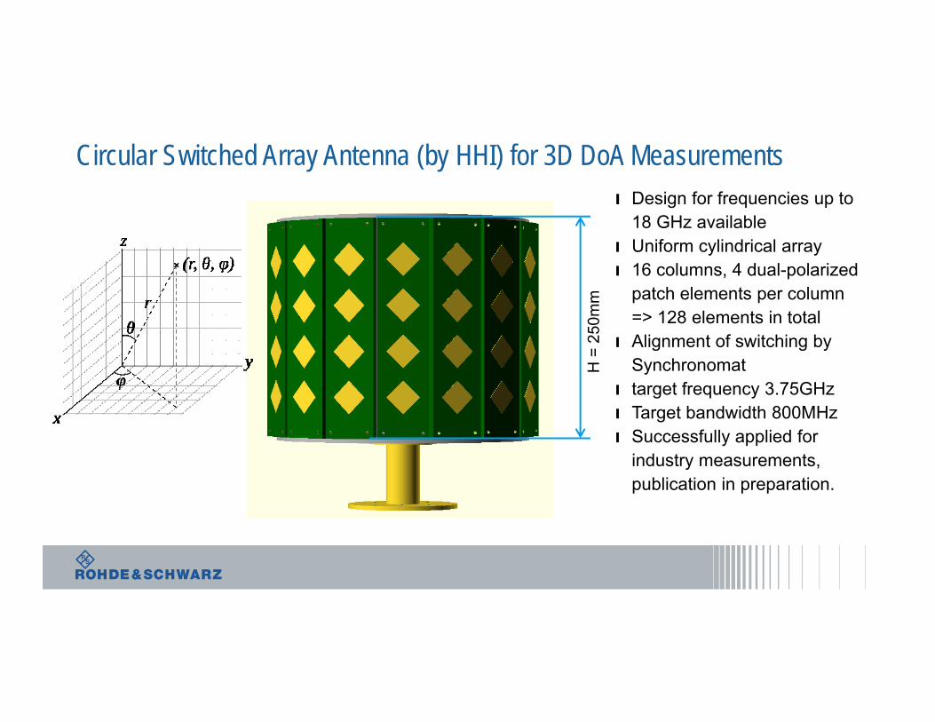
Circular Switched Array Antenna (by HHI) for 3D DoA Measurementsı Design for frequencies up to
18 GHz availableı Uniform cylindrical arrayı 16 columns, 4 dual-polarized
patch elements per column => 128 elements in total
ı Alignment of switching by Synchronomat
ı target frequency 3.75GHzı Target bandwidth 800MHzı Successfully applied for
industry measurements, publication in preparation.
H =
250
mm
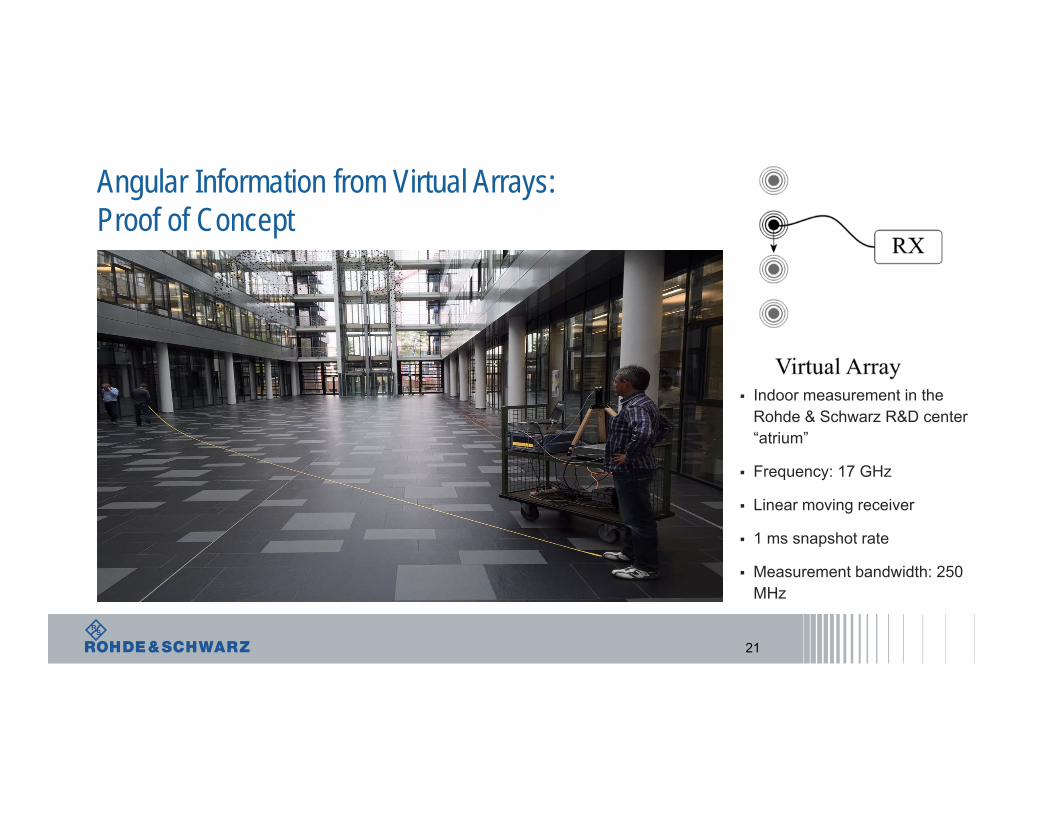
Indoor measurement in the Rohde & Schwarz R&D center “atrium”
Frequency: 17 GHz
Linear moving receiver
1 ms snapshot rate
Measurement bandwidth: 250 MHz
Angular Information from Virtual Arrays: Proof of Concept
21
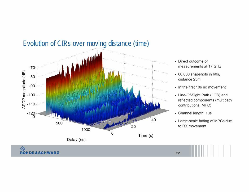
Direct outcome of measurements at 17 GHz
60,000 snapshots in 60s, distance 25m
In the first 10s no movement
Line-Of-Sight Path (LOS) and reflected components (multipath contributions: MPC)
Channel length: 1µs
Large-scale fading of MPCs due to RX movement
Evolution of CIRs over moving distance (time)
22
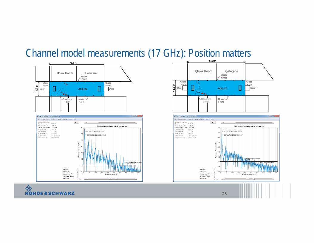
Channel model measurements (17 GHz): Position matters
23
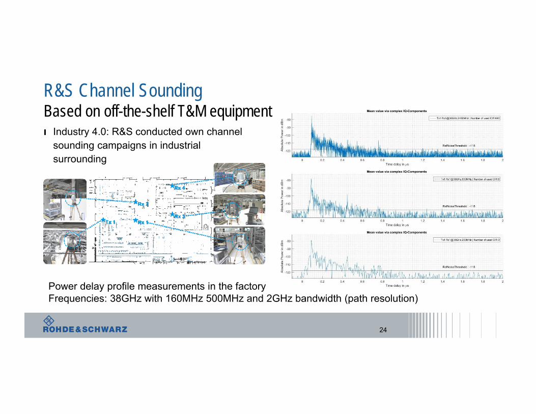
R&S Channel SoundingBased on off-the-shelf T&M equipment
24
Power delay profile measurements in the factory Frequencies: 38GHz with 160MHz 500MHz and 2GHz bandwidth (path resolution)
ı Industry 4.0: R&S conducted own channel sounding campaigns in industrial surrounding
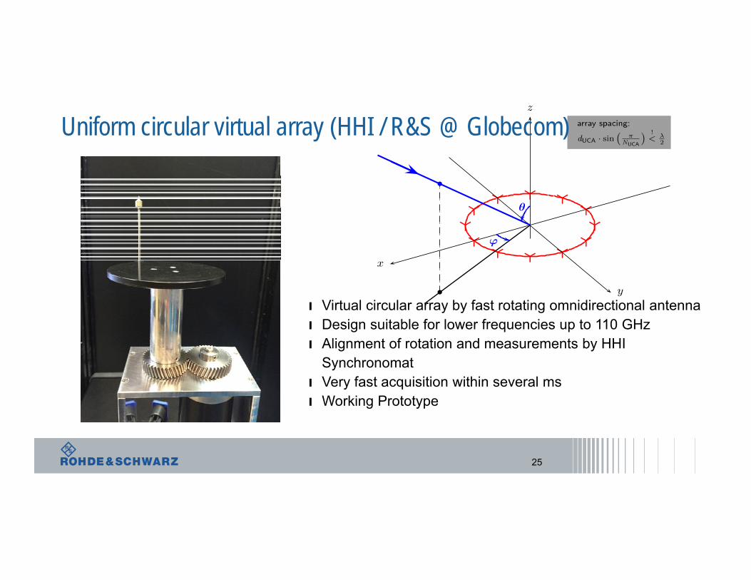
Uniform circular virtual array (HHI / R&S @ Globecom)
25
ı Virtual circular array by fast rotating omnidirectional antennaı Design suitable for lower frequencies up to 110 GHzı Alignment of rotation and measurements by HHI
Synchronomatı Very fast acquisition within several msı Working Prototype
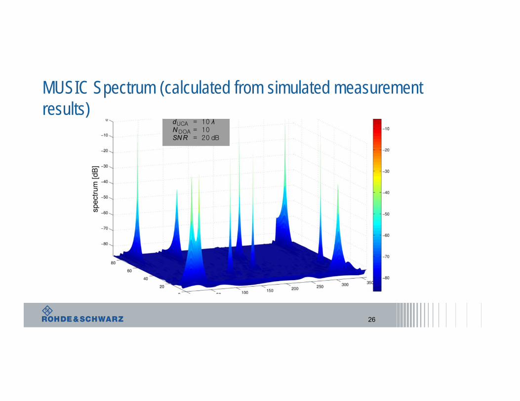
MUSIC Spectrum (calculated from simulated measurement results)
26
dUCA = 10 λNDOA = 10SN R = 20 dB
URLLC: The Road to 5G V2X
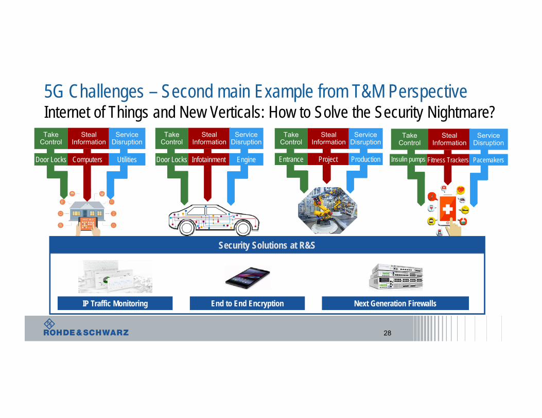
5G Challenges – Second main Example from T&M PerspectiveInternet of Things and New Verticals: How to Solve the Security Nightmare?
28
Take Control
Steal Information
Service Disruption
Door Locks EngineInfotainment
Take Control
Steal Information
Service Disruption
UtilitiesComputersDoor Locks
Take Control
Steal Information
Service Disruption
Insulin pumps PacemakersFitness Trackers
Security Solutions at R&S
IP Traffic Monitoring End to End Encryption Next Generation Firewalls
Take Control
Steal Information
Service Disruption
Entrance ProductionProject
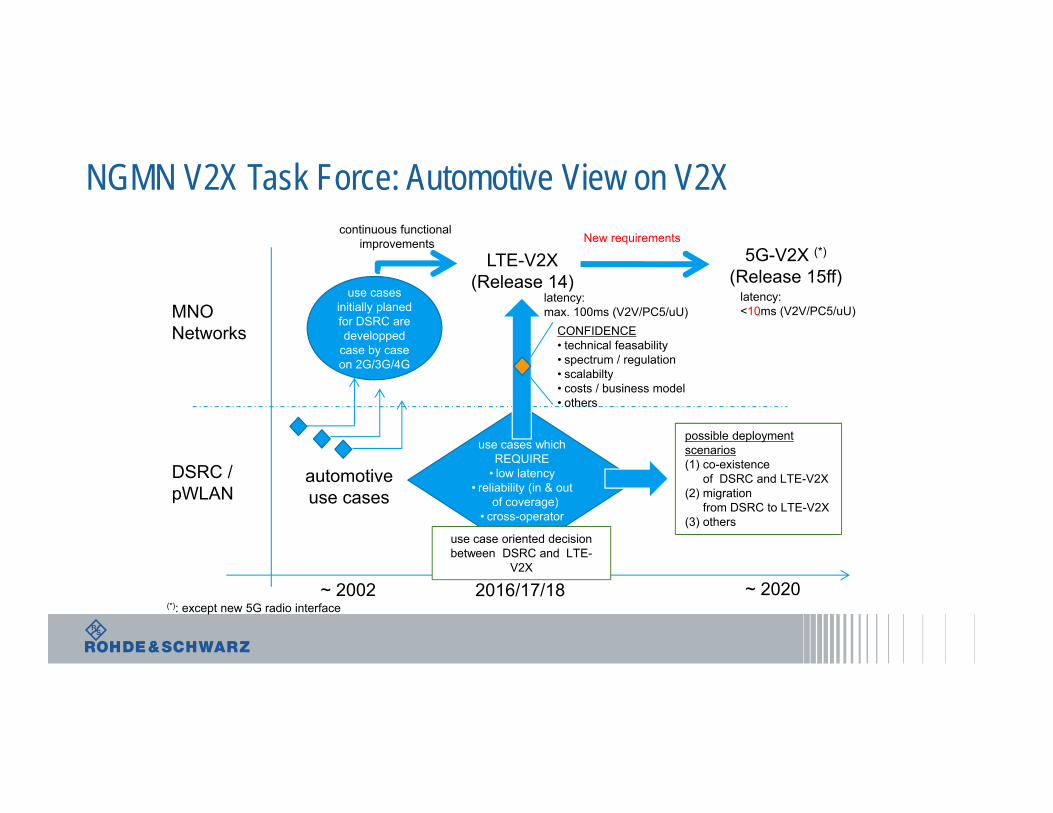
NGMN V2X Task Force: Automotive View on V2X
MNO Networks
DSRC /pWLAN
automotiveuse cases
use cases initially planed for DSRC are developped
case by case on 2G/3G/4G
use cases which REQUIRE
• low latency• reliability (in & out
of coverage)• cross-operator
LTE-V2X(Release 14)
CONFIDENCE• technical feasability• spectrum / regulation• scalabilty• costs / business model• others
5G-V2X (*)(Release 15ff)
possible deployment scenarios(1) co-existence
of DSRC and LTE-V2X(2) migration
from DSRC to LTE-V2X(3) others
New requirements
~ 2002 2016/17/18
continuous functional improvements
~ 2020
latency: max. 100ms (V2V/PC5/uU)
use case oriented decision between DSRC and LTE-
V2X
latency: <10ms (V2V/PC5/uU)
(*): except new 5G radio interface
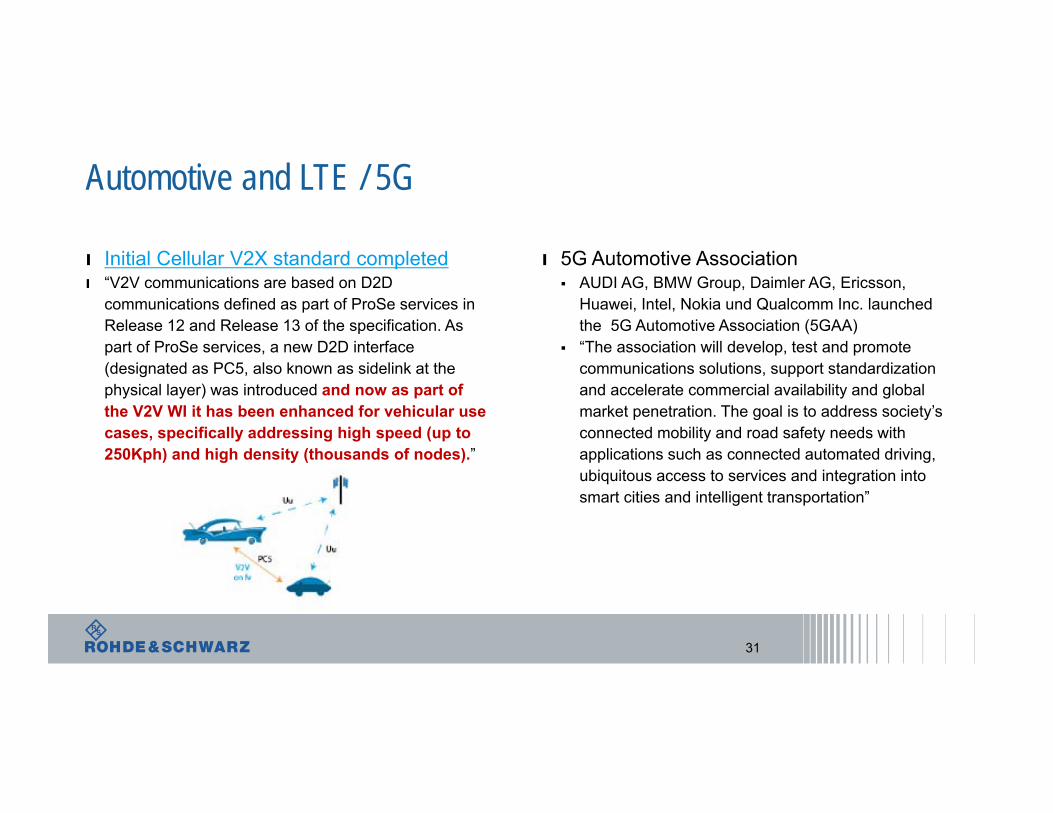
Automotive and LTE / 5G
31
ı Initial Cellular V2X standard completedı “V2V communications are based on D2D
communications defined as part of ProSe services in Release 12 and Release 13 of the specification. As part of ProSe services, a new D2D interface (designated as PC5, also known as sidelink at the physical layer) was introduced and now as part of the V2V WI it has been enhanced for vehicular use cases, specifically addressing high speed (up to 250Kph) and high density (thousands of nodes).”
ı 5G Automotive Association AUDI AG, BMW Group, Daimler AG, Ericsson,
Huawei, Intel, Nokia und Qualcomm Inc. launched the 5G Automotive Association (5GAA)
“The association will develop, test and promote communications solutions, support standardization and accelerate commercial availability and global market penetration. The goal is to address society’s connected mobility and road safety needs with applications such as connected automated driving, ubiquitous access to services and integration into smart cities and intelligent transportation”

Cross-Industry Collaboration: 5G Automotive Association
Automotive IndustryVehicle Platform, Hardware and
Software Solutions
TelecommunicationsConnectivity and Networking
Systems, Devices and Technologies
End to End Solutions for Intelligent Transportation, Mobility Systems and Smart Cities
Connect telecom industry and vehicle manufacturers; work closely together to develop end-to-end solutions for future mobility and transportation services, impact regulation and standardization
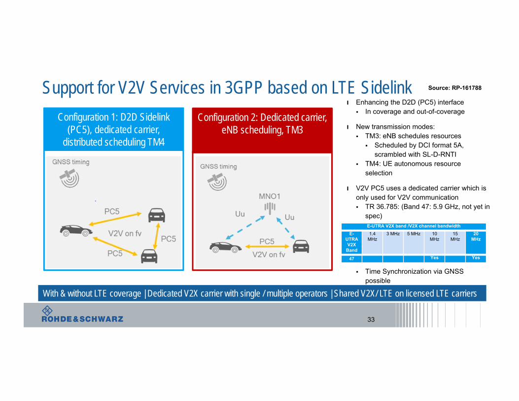
ı Enhancing the D2D (PC5) interface In coverage and out-of-coverage
ı New transmission modes: TM3: eNB schedules resources
Scheduled by DCI format 5A, scrambled with SL-D-RNTI
TM4: UE autonomous resourceselection
ı V2V PC5 uses a dedicated carrier which isonly used for V2V communication TR 36.785: (Band 47: 5.9 GHz, not yet in
spec)
Time Synchronization via GNSS possible
Support for V2V Services in 3GPP based on LTE Sidelink
33
Configuration 1: D2D Sidelink(PC5), dedicated carrier,
distributed scheduling TM4
Configuration 2: Dedicated carrier, eNB scheduling, TM3
With & without LTE coverage | Dedicated V2X carrier with single / multiple operators | Shared V2X/ LTE on licensed LTE carriers
Source: RP-161788
E-UTRA V2X band /V2X channel bandwidthE-
UTRA V2X
Band
1.4 MHz
3 MHz 5 MHz 10 MHz
15 MHz
20 MHz
47 Yes Yes
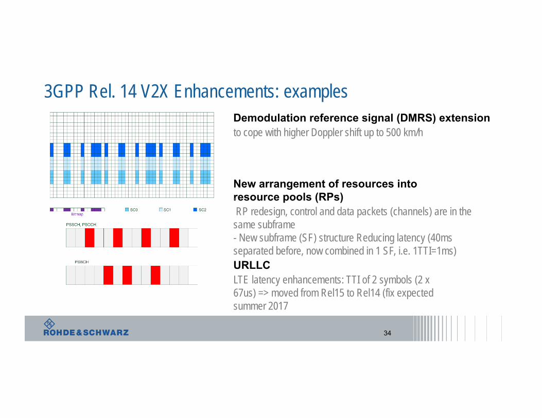
3GPP Rel. 14 V2X Enhancements: examples
34
New arrangement of resources into resource pools (RPs)-RP redesign, control and data packets (channels) are in the same subframe- New subframe (SF) structure Reducing latency (40ms separated before, now combined in 1 SF, i.e. 1TTI=1ms)
Demodulation reference signal (DMRS) extensionto cope with higher Doppler shift up to 500 km/h
URLLCLTE latency enhancements: TTI of 2 symbols (2 x 67us) => moved from Rel15 to Rel14 (fix expected summer 2017

5G – The Sophisticated Successor of 4G
From R&D .... .... To Production
Rohde & Schwarz is supporting the wireless communications industry with the solutions needed to investigate, develop and standardize 5G