Embed Size (px)
Citation preview

A1B15EN2
Topics
Electrical parameters of power lines and ES elements DC and AC power lines LV, MV HV power lines, substitution elements Meshed grids Electrical waves on power lines Short-circuits Ground faults Transmission stability Electrical protections Substations Grounding Dimensioning

References
[1] www.powerwiki.cz [2] Blume, Steven Warren. Electric power system basics: for the nonelectrical
professional [online]. Hoboken: Wiley, 2007 [cit. 2013-02-08]. Dostupné z: <http://onlinelibrary.wiley.com/book/10.1002/9780470185810>. ISBN 978-0-470-18581-0.
[3] El-Hawary, M. E. Introduction to electrical power systems [online]. New York: Wiley, 2008. IEEE Press series on power engineering [cit. 2013-02-08]. Dostupné z: <http://onlinelibrary.wiley.com/book/10.1002/9780470411377>. ISBN 978-0-470-41137-7.
[4] Hase, Yoshihide. Handbook of power system engineering. Chichester: Wiley, ©2007. xxvi, 548 s. ISBN 9780470033678.
[5] Saccomanno, Fabio. Electric power systems: analysis and control. Hoboken: Wiley, ©2003. xiii, 730 s. ISBN 0-471-23439-7.

[6] Kasicki, Ismail. Analysis and design of low-voltage power systems: an engineer's field guide. Weinheim: Wiley, ©2002. xxii, 387 s. ISBN 9783527602339.
[7] Kasikci, Ismail. Short circuits in power systems: a practical guide to IEC 60 909. Weinheim: Wiley, ©2002. xvi, 262 s. ISBN 9783527600465.
[8] Horowitz, Stanley H. a Arun G. Phadke. Power system relaying. 3rd ed. Chichester: Wiley, ©2008. xvi, 331 s. ISBN 9780470758786.

Overhead Power line Electrical Parameters
4 basic (primary) el. parameters (for each phase) Resistance R1 (Ω/km) Operational inductance L1 (H/km) Conductance G1 (S/km) Operational capacity C1 (F/km)
Secondary parameters inductive reactance
)km/(fL2LX 111 susceptance
)km/S(fC2CB 111 longitudinal impedance
)km/(jXRZ 111l

cross admittance )km/S(jBGY 111q
wave impedance
)(YZZ
1q
1lv
propagation constant )km(jYZˆ 1
1q1l
α – specific damping β – specific phase shift
Note: - we consider symmetrical supply and load - networks LV – mainly R
MV – R, L (in failures C) HV – R, L, G, C (distributed)

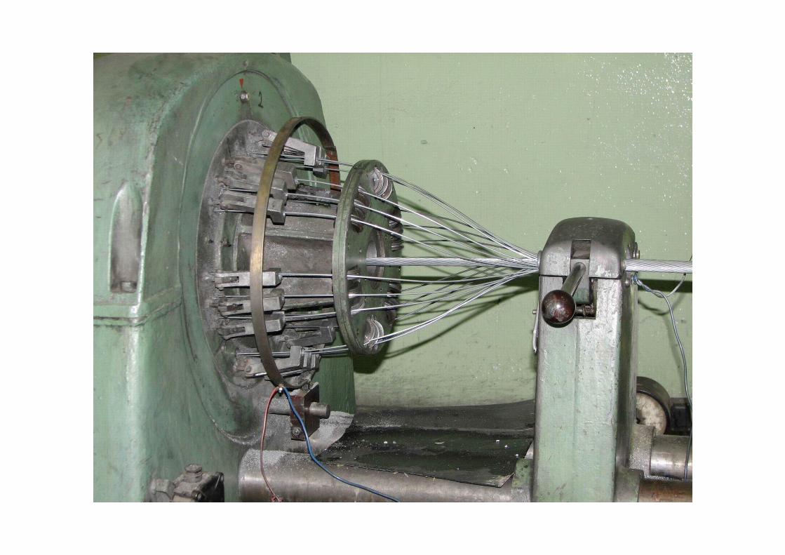
Overhead power line conductors - full cross section or twist (1 or more materials) - ropes Cu, Al, alloys, composites, optical wires, high-temperature
materials - ACSR (Aluminum Conductor Steel Reinforced) = carrying Fe core
+ conductive Al coat 2mm680;180S
- example of labeling 382-AL1/49-ST1A 350AlFe4 AlFe450/52
Rope Construction
Fe Al Rope Nb. of wires
Diameter of wire
Diameter of inner tube
Cross-section
Nb. Of wires
Diameter of wire
Cross-section Diameter Cross-
section RDC+20
ks mm mm mm2 ks mm mm2 mm mm2 ·km-1350 AlFe 4 1+6+12/12+18 19 2,36 11,80 83,11 30 3,75 331,34 26,80 414,45 0,087 450 AlFe 8 3+9/18+14+20 12 2,36 9,90 52,49 18+34 1,90+3,75 426,55 28,70 479,05 0,0674
AlFe 450/52 3+9/12+18+24 12 2,36 9,81 52,49 54 3,25 447,97 29,31 500,46 0,0646 382-AL1/49-ST1A 1+6/12+18+24 7 3,00 3,00 49,48 54 3,00 381,70 27,00 431,18 0,0758 476-AL1/62-ST1A 1+6/12+18+24 7 3,35 10,05 61,70 54 3,35 475,96 30,15 537,66 0,0608


Resistance
Value influenced by: conductor material, temperature, skin effect, elongation due to twisted wires, current density distribution along stripes, sag, unequal cross section, connections
With DC current (at 20C)
)km/(S
R 00dc1
Cu: )m(1078,1 80
Al: )m(1081,2 8
0
Fe: )m(108,12 80
FeAl
FeFeAlAlAlFeDC SS
SS

Temperature effect )()TT()TT(1k 2
0101T Cu: )K(1093,3 13 Al: )K(1003,4 13
Fe: )K(105,4 13 26 K10 → under normal ΔT neglected
Fe
FeFe
Al
AlAl
Fe
Fe
Al
Al
Al
AlFe
Fe
FeAl
Fe
Fe
Al
AlFeAl
SSSS
SSSS
Influence of AC current, e.g. 1
2
0dc12
1212ac m,m,Hz,m,m;
Rrfrr100375,01k

)(3,1004,1kac Empirically by the number of layers Al (Fe core 2÷3% of current)
two layers 04,1kac three layers 06,1kac four layers 05,1kac
In catalogue usually R1dc0 )km/(kkRR acT0dc11
km/2;05,0Rcca 0dc1
AlFe42 R1dc0 ~ 0,7 Ω/km AlFe210 R1dc0 ~ 0,14 Ω/km AlFe70 R1dc0 ~ 0,4 Ω/km AlFe350 R1dc0 ~ 0,09 Ω/km AlFe95 R1dc0 ~ 0,3 Ω/km AlFe450 R1dc0 ~ 0,07 Ω/km AlFe120 R1dc0 ~ 0,2 Ω/km AlFe680 R1dc0 ~ 0,04 Ω/km

Inductance and longitudinal impedance
Inductance and impedance in a loop
,, kkkkIIddldr

Internal inductance of a conductor (magnetic flux inside the conductor)
),,m/H;m/H(8
L rv0ik
17
0 mH104 rv ....... relative permeability of conductor α ......... inequality of current distribution through cross-section
External inductance of a conductor in a loop (magnetic flux outside the conductor)
)m,m,m/H;m/H(rdln
2L 0
ek
Self-inductance
rdln
28LLL 0rv0
ekikv
)m,m;kmmH(r
dlog46,0rdlog46,005,0L 1
rvv

ξ… coefficient of current density inequality in cross section and permeability
46,005,0
10
rv
826,0;809,0 for common ACSR ropes
Impedance of one conductor in a loop of two conductors
16k1kv m
rdlog1046,0jRZ

Self-impedance of a loop conductor-ground - Ground as a conductor of stationary AC current - Rüdenberg’s conception - Density of AC current in a ground is unequal, the maximum is under
the conductor

3 components: a) R1k – resistance respecting power losses in the conductor b) X1k – reactance respecting part of magnetic flux coupled with the
conductor and closed in the conductor and in the air c) Z1g – impedance respecting part of magnetic flux in the ground
coupled with conductor g1g1k1k1kkkkkk jXRjXRjXRZ
)Hz;m(10fR 172g1
for f = 50 Hz je
1g1 km0495,0R
1g342k1kk km
rD
log46,010j10fRZ

Fictitious conductor deep in the ground which has the same impacts as the real current in the ground
)Hz,m;m(f
10178,0D
7
g
Dg ~ 100x m, i.e. h<<Dg
ρ…ground resistivity
Type of soil ρ (Ω·m)peat 30 topsoil and clay 100 moist sand 200 - 300 dry gravel and sand 1000 - 3000 stony soil 3000 - 10000

Mutual impedance of two loops conductor-ground - double wire one-phase power line hdkm → return currents are compensated by each other

kmg dD → resulting electromagnetic impacts of return currents in the conductors k´, m´ on the real conductors k, m is almost zero
Impedance of one conductor in a loop mkmkkkkkvkv IZIZIZU
kmkkkvmk ZZZII Hence after substitutions
1g3g1k1kk km
rD
log46,010jRRZ
1km3k1kv km
rdlog1046,0jRZ
1
km
g3g1kvkkkm km
dD
log46,010jRZZZ

Configuration of n real conductors
Configuration of loops n real conductors and the ground is substituted by n real and n fictitious conductors in mutual distance Dg.

Self-inductance and impedance (loop k-k´)
)m,m;km/mH(r
Dlog46,0M
k
gkk
rk…kth conductor radius
kmrD
log1445,0jRRLjRZk
gg1k1kkkkkk
Mutual inductance and impedance (loop k-k´, m-m´)
)m,m;km/mH(MdD
log46,0M mkkm
gkm
kmd
Dlog1445,0jRLjRZZ
km
gg1kmkmmkkm

Voltage drop in kth conductor
)km/V(IZUn
1mmkmk
(for km is kkk rd ) Operational impedance (inductance) – for 1 single conductor, it causes the same voltage drop as in the system of n conductors (it can be a complex number, done by operating condition)
k
n
1mmkm
kkk
n
1mmkmk I
IZZIZIZU
k
n
1mmkm
k I
IML
n-conductor system ]I][M[j]U[ km

Simple (unbalanced) three-phase power line
Symmetrical loading
ac
a2
b
aa
IaI
IaI
II
0aa1
e23j
21a
e23j
21a
2
32j2
32j

Operational inductances
acab2
aaa
cacbabaaaa MaMaM
IIMIMIML
bc2
bbabb
cbcbbbaabb MaMMa
IIMIMIML
ccbcac2
c
cccbbcaacc MMaMa
IIMIMIML
Generally ccbbaa MMM acbcab MMM
cba LLL → unequal voltage drops (magnitude and phase) → voltage unbalance, active power transfer between phases through electromagnetic coupling without further sources loading → transposition

Transposition of three-phase power line
= conductors position exchange so that each one is in a definite position for 1/3 length
Voltage drops
c
b
a
111312
133323
122322
221223
121113
231333
332313
232212
131211
c
b
a
III
MMMMMMMMM
MMMMMMMMM
MMMMMMMMM
j31
UUU


Let’s mark
)MMM(31M 332211
)MMM(31'M 231312
Then
a
a2a
c
b
a
IaIa
I
M'M'M'MM'M'M'MM
jUUU
Phase operational inductances at transposed and symmetrically loaded power line are equal and real: 'Ma'MaML 2
a 'MMLLL cba

After substitution
)km/mH(r
Dlog46,0M g
)km/mH(d
Dlog46,0'M g
mean geometrical distance 3
231312 dddd
Finally
)km/mH(r
dlog46,0LLLL cba1
kmrdlog1445,0jRZZZ 11

Double power lines with two ground wires

2z
1z
C
B
A
c
b
a
2z2z1z2zC2zB2zA2zc2zb2za2z
2z1z1z1zC1zB1zA1zc1zb1za1z
2Cz1CzCCCBCACcCbCa
2Bz1BzBCBBBABcBbBa
2Az1AzACABAAAcAbAa
2cz1czcCcBcAcccbca
2bz1bzbCbBbAbcbbba
2az1azaCaBaAacabaa
2z
1z
C
B
A
c
b
a
IIIIIIII
ZZZZZZZZZZZZZZZZZZZZZZZZZZZZZZZZZZZZZZZZZZZZZZZZZZZZZZZZZZZZZZZZ
UUUUUUUU
After modifications it can be written (assumption of continuous grounding of ground wires)
zzzVzVvzvz
zVzVVVvVvV
zvzVvVvvvv
IZIZIZU0
IZIZIZU
IZIZIZU

currents in ground wires VzVvzv
1
zzz IZIZZI
For modified power line
VzV
1
zzVzVVvzv
1
zzVzVvV
VzV
1
zzvzvVvzv
1
zzvzvvv
IZZZZIZZZZU
IZZZZIZZZZU
- it is an imaginary power line without ground wires which would act as a real power line with ground wires
- for impedances transfer to symmetrical components system

Power line with bundle conductors
Bundle conductor - each phase composed of n partial conductors connected in parallel - arranged in regular n-polygon - increases initial corona voltage - from voltage 400 kV higher
U (kV) 400 750 1150 1800 n 3 4 8 16
- a400kV = 40 cm

Czech Republic: 400 kV – triple-bundle conductor

Kladno (CR) 110 kV (2), Canada 750 kV (4), China 1000 kV (8)

Operational inductance
)km/mH(r
dlog46,0Lee
1
equivalent bundle radius
n
e RnrRr
equivalent coefficient n
e
→ bundle conductor decreases L, R (conductors in parallel), increases C
22 kV X ~ 0,35 /km 110 kV X ~ 0,35÷0,4 /km 220 kV X ~ 0,4 /km 400 kV X ~ 0,3 /km 750 kV X ~ 0,25 /km

Zero sequence reactance Fe grounding wires - X0 ~ (3,5÷5,5)X1 ACSR grounding wires - X0 ~ (2÷4)X1

Conductance
It causes active power losses by the conductance to the ground (through insulators, corona – dominant at overhead power lines). It depends on voltage, climatic conditions (p, T, humidity), conductors. Less dependant on loading.
Calculation from corona losses 12
12f1SfS kmWUGUG3IU3P
)V,km/W;km/S(UP
G 2S
1 16
118
1 kmS10BxkmS10G
U (kV) G1 (S/km) U (kV) G1 (S/km) 110 (3,6 ÷ 5)·10-8 750 (1,3 ÷ 2,5)·10-8
220 (2,5 ÷ 3,6)·10-8 1150 (1,0 ÷ 2)·10-8 400 (1,4 ÷ 2)·10-8