Embed Size (px)
Citation preview

EN Rating

2
Specifications
UPPER REVOLVING FRAME:All-welded, precision machined, robustconstruction. Provided with machined surfacefor mounting load hoist and slewing unitassemblies, and mounting itself on turntablebearing. For structural integrate alignment ofa 4-section telescopic boom and boom hoistcylinder, boom and cylinder foot pin holes areprecisely machine bored too.
TURNTABLE BEARING WITH INTERNAL SLEWING GEAR:Single shear ball type; inner race of turntablebearing with integral, internal slewing (ring)gear bolted to lower frame, and outer race ofturntable bearing bolted to upper revolvingframe.
CONTROL SYSTEM:System contains two sets each ofquadruplicate and single tandem valves whichdirect oil to various machine function and areactuated by control levers via remotecontrolled hydraulic servo for all motions.Working speeds can be precisely controlledby pilot-operated two universal joystick andthree floor control levers including two asstandard for travel and one as optional foraux. crane hoist drum controls. System takesan unique hydraulic circuit to maximize drumhorsepower, and reduce horsepower loss witheliminating the possibility of engine stall.
HYDRAULIC SYSTEM:System provided with two variabledisplacement axial piston pumps each of29.4MPa<300kg/cm2>/216Lpm capacity, andone fixed displacement axial piston pump of27.4MPa<280kg/cm2>/135Lpm capacity forboth independent and combined operations ofall functions, and one fixed displacementgear pump of 4.9MPa<50kg/cm2>/32.4Lpmcapacity for system valve and cylindercontrols.
Main/opt. aux. crane hoist motors — Variable dis-placement axial piston motor withcounterbalance valve.
Slewing motor — Fixed displacement axial pistonmotor with spring-applied/power hydraulicallyreleased multiple wet-disc type brake forparking.
Travel motors — Shoe-in design; fixed displacementaxial piston motor with brake valve andspring-applied/power hydraulically releasedmultiple wet-disc type automatic brake.
Pressure settings — Rated and over-load reliefpressure in each hydraulic circuit is set asunder:¡Rated pressure settings:
Main crane hoist..................................29.4MpaBoom telescoping ................................20.7MpaBoom elevation....................................23.1MpaTravel .................................................24.0MpaSlewing...............................................23.0MpaPilot .....................................................4.9Mpa
¡Over-load relief pressure settings:Main crane hoist..................................31.4MpaBoom telescoping ................................29.0MpaBoom elevation....................................27.6MpaTravel .................................................24.0Mpa
SuperstructureHITACHI SUMITOMO

3
Oil cooler — Aluminum-make; available for not only agood rustproof but also high coolingefficiency.
Hydraulic oil reservoir — 450 liters capacity.Kind of hyd. oil — Standardized with ISO VG46
having viscosity ranging from 41.4 thru50.6mm2/sec at 40°C.
Line filters — A 12 microns high-filtration full-flowfilter element is incorporated in return line,and pilot f i l ters and suction f i l ters aredesigned for a good hydraulic oil filtration.
LOAD HOIST ASSEMBLY:Main crane hoist drum driven by hydraulicmotor of bi-directional, variable displacementaxial piston motor through a 2-stage planetaryreduction gear unit powering the rope drum ineither direction for hoisting and lowering load.Reduction gear unit installed within druminside to realize a wider drum width. And,Power load lowering is only available as noclutch design is applied.
Brakes — Spring applied, power hydraulicallyreleased multiple wet-disc type automaticbrake; provided within hyd. motor.
Drum — One piece, parallel grooved lagging withlocking ratchet wheel cast integral; driven bya planetary reduction gear unit that involute-splines to drum shaft. Available to wind upapprox. 25m long cable of 18mm dia. at drum1st layer.
Drum locks — Electrically operated pawl.Aux. crane hoist drum — Optional extra; available in
the same design as that of standardized maincrane hoist drum.
SLEWING:Driven by a bi-directional, axial pistonhydraulic motor through 2-stage planetaryreduction gear unit powering slewing pinion.Slewing pinion meshes with internal teeth ofslewing (ring) gear of turntable bearing innerrace.
Brakes — Spring-applied, power hydraulicallyreleased multiple wet-disc type; providedwithin hydraulic motor.
Lock — Mechanically operated drop pin.Speed — 3.7min–1 <3.7rpm>.
OPERATOR’S CAB:A 940mm wide, acoustically treated, full-vision, cushion rubber mounted, well-ventilated, full compartment, roomy operator’scab with a large front window with safetyglass; provided with an arrangement of controlstation with two universal joystick, two traveland one optional aux. crane hoist drumcontrol levers, sunvisor, sunshade, rear-viewmirrors, an intermittent type window shieldwipers with washer on both front and roofwindows, sliding windows on left-hand sidecab, and roll-down window on cab slidingdoor.
Instrument panel — Contains engine monitoringlamps, English WYLIE brand Load MomentIndicator, gauges & meter, warning lamps andother necessary controllers and switches.
Operator’s seat — Full adjustable reclining seat withhead rest and both R/H and L/H side armrests.
Anemometer — Optional extra; Air-conditioner — Provided as std.; built-in type full
air-conditioning.Electric cab fan — Optional extra; wind-direction
adjustable type.Engine foot throttle — Available in two(2) throttles of
right-and-left-hand foot pedal and handthrottle.
Operator’s cab side step — Available for accessease to operator’s cab.
AM/FM radio — Provided as std. with clock.Fire extinguisher — Optional extra; powder type.
MACHINERY CAB:Equipped with hinged doors on both sides formachinery access and inspection; affixed withtape-type non-skid material on the roof.
COUNTERWEIGHTS:Weighs 11.5ton with a 4-removable blockconsisting of “A” (4,900kg), “B” (2,800kg), “C”(2,800kg) and “D” (1,000kg).
ELECTRICAL SYSTEM:24-volt negative ground system; provided withtwo maintenance free batteries of12V×150AH.
LIGHTING SYSTEM:Includes following lights.• Two 70 W working lights;• One 10 W interior cab light.
REAR VIEW MIRRORS:Two; provided on front-left and -right corners ofsuperstructure.
MICROPHONE & LOUD-SPEAKER:Optional extra; this is for operator’sconvenience for loud speaking.
POWER UNIT:
〈 〉 ・
〈 〉
��� ������ ��� ���� ���� � �������� ���� ������ ����������� ������� ������� ��� �������� ���� ������ ������!�� ��!��"�#� � ������� ����� � ����������������� ������ ������!����������� ������� !���� �������������$ ������!�� ��� �������������� ���#� "� �%����� ��������� ���#��
SCX400T

LOWER FRAME:All-welded, precision machined, box typeconstruction; provided with four axle tips, and aclearance adjusting mechanism for better fittingbetween axles and crawler side frames.Provided a machined surface for mountingturntable bearing.
CRAWLER SIDE FRAMES:All-welded, box type construction, precisionmachined; each slide-assembled along lowerframe axle tip boxes, and held in place byplate links with pins.
Retract unit — Available to power hydraulicallyextend/retract the crawler side frames.Controlled from operator's cab.
DRIVE SPROCKETS:Cast steel, heat treated; one per side frame.Track drive sprocket assembly bolt-coupled to2-stage planetary reduction gear unit outercase as an integral part of shoe-in typetraction motor. Sealed between parts ofrotation and non-rotation of the motor withfloating seal.
IDLER WHEELS:Cast steel, heat treated; one per side frame.Mounted on two bronze bushings with floatingseals for lifetime lubrication.
TRACK ROLLERS:Ten per side frame; each heat-treated caststeel with double flange design. All mountedon two bronze bushings with floating seals forlifetime lubrication.
CARRIER ROLLERS:Two per side frame; each heat-treated caststeel with double flange design. All mountedon two bronze bushings with floating seals forlifetime lubrication.
TRACKS:Tractor type; provided with induction-hardened, alloy, triple grouser shoes, andheat-treated track link pins with dirt seals;56 pcs. per side frame.
Shoe width — 810mm wide.Track adjustment — Hydraulic track adjustment with
shock-absorbing recoil spring is provided oneach track.
TRAVEL AND STEERING:A bi-directional, shoe-in type axial pistonhydraulic motor bolt-couples with drive sprocketthru 2-stage planetary reduction gear unit outercase at each crawler side frame end for traveland steer. Straight-line travel (forward or reverse),pivot or differential turns, and counter-rotation forspin turns are available.
Brake — Spring-applied, power hydraulically releasedmultiple wet-disc type automatic brake; locatedwithin hydraulic motor. Brakes automaticallyset when travel levers are in neutral or whenengine is shut down.
Travel speed — 1.9km/hr. (based on flat, level andfirm supporting surface, and under theconditions that no load must be applied andfront-end att. must be the standardized 4-section telescopic boom only).
Gradeability — 40% (22°) permissible based on basicmachine without front-end attachment.
LOAD MOMENT INDICATOR:English WYLIE brand; this is a fullcomputerized automatic over-load preventionsystem which meets EN Standards; Included inthe design is (1) no zero-point adjustment, (2)operator selected crane configuration on graphicdisplay panel (3) optional range and slew anglelimit settings.
Construction (standard version) — Comprises (1)pressure transducers (2) boom anglesensor/length sensor (3) computerized MicroProcessing Unit (M.P.U.) and (4) graphicdisplay panel.
Functions — This system functions by informing thecrane Operator with the activation of a yellowLED and internal buzzer when the load liftedreaches 95% of the cranes capacity and by ared LED and external audible alarm when thelifted load exceeds 102.5% of the cranescapacity. At this point the unsafe motlons ofthe crane are automatically stopped. Thesafe motions are allowed except for the boomup operation that is only allowed by theoperation of a spring return switch in theoperators cabin.
Display panel design — A graphic display panel inclear view to the operator allows the inputting ofthe cranes configuration. It displays all relevantinformation including “Allowable rated load”,“Actual lifted load” and the cranes currentstatus “Utilisation bargraph”, “Radius”, “Boomlength”, “Boom angle”, “Parts of hoist”, “Winchselected” etc. If option is installed the operatorcan also select a working range and thecrane will be automatically restricted to workonly in the pre-defined area.
DRUM ROPE OVER-PAYOUT LIMITER:Optional extra; Available on both main andopt. aux. crane hoist drums, and functions toautomatically stop drum rotation when no. ofrope winding at 1st layer becomes three(3).
4
Safety Devices
Undercarriage

5
HOOK OVER-HOISTING LIMITER:Limit switch type. Available to prevent hookover-hoisting with functions of automatic drumbraking with hydraulic lock, and warning bybuzzer.
SLEW LOCK:Mechanically operated drop pin; available tofirmly lock superstructure in two positions offacing front and rear to undercarriage.
DRUM LOCK:Electrically operated pawl locks is available onmain crane hoist drum.
SLEWING BRAKE SAFETY CIRCUIT:Available not to start engine wheneverslewing brake is off.
HOOK LATCH:Provided on every kinds of hook to preventout of place of cable from hook.
SLEWING ALARM:This is by buzzer, and flasher lamps locatedon both sides of machinery cab.
SIGNAL HORN:Available as warning just before every kindsof motions are initiated.
LOCK LEVER (FOOL PROOF SHUT-OFF LEVER):Located in the cab exit; this is available toautomatically deactivate and lock hydraulicsystem.
LMI SAFETY CIRCUIT-OFF SWITCH:Available in key type for a good crane safetyoperation management without fail.
GAUGES & METER:Engine water temperature gauge, fuel gaugeand hour-meter are provided on instrumentpanel.
ENGINE MONITORING LAMPS:Available to let operator warn engine abnormalconditions as to battery charge, lubrication oilpressure, radiator coolant level, oil filterclogging, air filter clogging, water temp., andglow plug; provided on instrument panel.
THREE COLOR PERCENTAGE INDICATOR:Optional extra; This is with three colors ofGreen, Yellow and Red. Each color indicatesthe load percentage to rated capacity; Greenshows less than 95% as safety, Yellow shows95 to 102.5% as marginal, and Red shows over102.5% as over-loading. As further function,Red lamp comes on automatically whenoperator cuts off safety circuit of the LMIabsentmindedly.
LEVEL GAUGE:Optional extra; bubble type. Located onoperator’s cab floor of superstructure.
AUX. HOOK OVER-HOISTING LIMITER:Optional extra; this is available for auxiliarycrane hoist with optional aux. auxiliary liftingsheave, Performs the same function as that of“Hook over-hoisting limiter” mentioned before.
SCX400T
BOOM:A 4-section full power, box construction, telescopic boom under American Link-Belt's patented design; boom side platesis designed with diamond shaped impressions for superior strength to weight ratio and 689.5MPa angle chords for lateralstiffness. In addition, boom telescope sections are supported by adjustable side wear shoes both vertically andhorizontally to prevent metal-to-metal contact.Length...........................................................10.06m to 32.00m with a 4-section.Boom telescoping.........................................Available in two modes of “B” and “A” as under:
Mode “B” — This is basic mode, and is the full power, synchronized mode oftelescoping all sections proportionally.
Mode “A” — This is an exclusive mode to extend only 2nd section to 17.37moffering increased capacities for in-close, maximum capacity picks.
Boom telesoping speed — Approx. 70 sec. (from 10.06m to 32.00m).Boom head ...................................................Four(4) head and two(2) guide of 0.42m root diameter nylon sheave mounted
on anti-friction bearing; provided with quick cable reeve design, and easilyremovable cable guards.
Boom elevation......................................Available from -3°to78°; provided with one Link-Belt designed hydrauliccylinder with holding valve and bushing in each end.Boom elevating speed — Approx. 40sec. (from zero to 78 degrees).
Front-end Attachment
6
���
���
���
� � � � � �
����
�
�
����
�
�
����
����
�
���
���
�
���
���
�
����
����
����
����
����
����
���
���
���
�� � � � � � � � ���
��
��� �������������� ��
���� �����
���� ���� �� ������ ����
�������� �������� ������������ ����
� !��
� !��"������� ����#�
������ �����
"������� ����#�
������ �����$ % &'���
$ % &'���
$(��
$(��
(')*〈(�+�〉
(')*〈(�+�〉
���
,������ -������
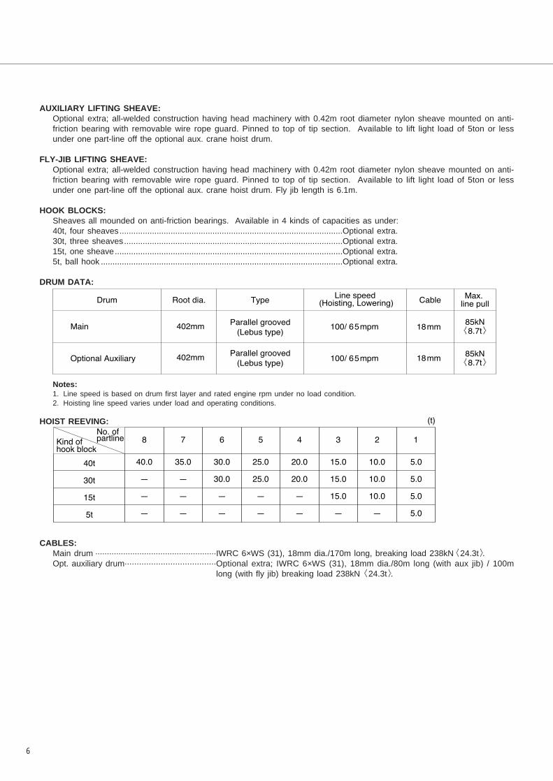
AUXILIARY LIFTING SHEAVE:Optional extra; all-welded construction having head machinery with 0.42m root diameter nylon sheave mounted on anti-friction bearing with removable wire rope guard. Pinned to top of tip section. Available to lift light load of 5ton or lessunder one part-line off the optional aux. crane hoist drum.
FLY-JIB LIFTING SHEAVE:Optional extra; all-welded construction having head machinery with 0.42m root diameter nylon sheave mounted on anti-friction bearing with removable wire rope guard. Pinned to top of tip section. Available to lift light load of 5ton or lessunder one part-line off the optional aux. crane hoist drum. Fly jib length is 6.1m.
HOOK BLOCKS:Sheaves all mounded on anti-friction bearings. Available in 4 kinds of capacities as under:40t, four sheaves................................................................................................Optional extra.30t, three sheaves..............................................................................................Optional extra.15t, one sheave..................................................................................................Optional extra.5t, ball hook ........................................................................................................Optional extra.
DRUM DATA:
Notes:1. Line speed is based on drum first layer and rated engine rpm under no load condition.2. Hoisting line speed varies under load and operating conditions.
HOIST REEVING:
CABLES:Main drum ....................................................IWRC 6×WS (31), 18mm dia./170m long, breaking load 238kN〈24.3t〉.Opt. auxiliary drum......................................Optional extra; IWRC 6×WS (31), 18mm dia./80m long (with aux jib) / 100m
long (with fly jib) breaking load 238kN〈24.3t〉.

7
■LIFTCRANE CAPACITIES (1) - Boom telescoping mode B
Liftcrane 40 metric tons - EN Rating
10.06 12.19 15.24 18.29 21.34 24.38 27.43 30.48 32.00Boom length (m)
Working radius (m)
2.5
3.0
4.0
5.0
6.0
7.0
8.0
9.0
10.0
11.0
12.0
13.0
14.0
15.0
16.0
17.0
18.0
19.0
20.0
21.0
22.0
23.0
24.0
25.0
26.0
27.0
40.00
35.00
28.40
22.50
16.90
13.30
11.70/7.6
15.80
15.80
15.80
15.80
13.40
11.00
9.20
15.80
15.80
15.80
15.80
13.50
11.10
9.30
7.90
6.90
6.00
5.80/12.2
15.80
15.80
15.80
15.80
13.60
11.20
9.40
8.00
6.90
6.10
5.30
4.70
4.20
4.10/15.2
15.80/4.6
15.80
15.80
13.70
11.20
9.40
8.10
7.00
6.10
5.40
4.80
4.30
3.80
3.50
3.10
13.80/6.1
12.40
11.00
9.50
8.10
7.00
6.20
5.40
4.80
4.30
3.90
3.50
3.10
2.80
2.60
2.30
12.20/6.1
11.20
10.10
9.10
8.10
7.10
6.20
5.50
4.90
4.30
3.90
3.50
3.20
2.90
2.60
2.40
2.20
1.90
1.70
9.40/7.6
9.10
8.40
7.70
7.10
6.20
5.50
4.90
4.40
3.90
3.50
3.20
2.90
2.60
2.40
2.20
1.90
1.70
1.60
1.40
1.20
7.90/7.6
7.90
7.90
7.30
6.70
6.20
5.50
4.90
4.40
3.90
3.50
3.20
2.90
2.60
2.40
2.20
2.00
1.70
1.60
1.40
1.20
■WORKING MASS & GROUND CONTACT PRESSURE:
Note: Working mass shown above is with a 4-sectiontelescopic boom, 11.5ton counterweight, and 40thook block.
���� ���� ��� �������
����� ���� ����� � ������������
■LIFTCRANE CAPACITIES (2) - Boom telescoping mode A10.06 12.19 15.24 17.37
Boom length (m)Working radius (m)
2.5
3.0
4.0
5.0
6.0
7.0
8.0
9.0
10.0
11.0
12.0
13.0
14.0
15.0
16.0
40.00
35.00
28.40
22.50
16.90
13.30
11.70/7.6
32.50
27.00
21.70
16.60
13.00
10.60
8.80
31.50
26.00
21.00
16.30
12.80
10.40
8.70
7.30
6.30
5.40
5.30/12.2
19.50
19.00
16.80
14.50
12.50
10.30
8.60
7.20
6.20
5.30
4.60
4.10
3.50
3.40/15.2
SCX400T

8
Notes — Liftcrane capacities1. GENERAL:(1) WARNING !! IT IS A MUST TO READ AND UNDERSTAND THE
OPERATOR'S MANUALS AND THE FOLLOWINGINSTRUCTIONS AND RATED LIFTING CAPACITIES BEFOREOPERATING CRANE. OPERATION WHICH DOES NOT FOLLOWTHESE INSTRUCTIONS MAY RESULT IN AN ACCIDENT.
(2) Capacities are in metric tons, and are rated in accordancewith ENI3000 Standard; the figures surrounded by bold linesare based on the factor of machine structural strengthlimitations according to ENI3000 Standard or hydrauliclimitations.
(3)Rated lifting capacities as shown on these charts pertain tothis crane as originally manufactured and normally equipped.Modifications to the crane or use of optional equipment otherthan that specified can result in a reduction of capacity.
(4) Construction equipment can be dangerous if improperlyoperated or maintained. Operation and maintenance of thiscrane must be in compliance with the instruction/informationin the Operator's and Parts Manuals supplied with this crane.If these manuals are missing, it is certain'y required to orderus or nearest distributor the replacements.
(5) The operator and other personnel associated with this craneshall read and fully understand the latest applicableEuropean safety standards like EN414.
(6) The rated lifting capacties are based on crane standing levelon firm supporting surtace.
2. SET-UP:(1) The crane shall be leveled on a firm supporting surface.
Depending on the nature of the supporting surface, it may benecessary to have structural supports under the crawlershoes for its level.
(2) When making l i f ts, crawler side frames must be fullyextended.
(3) An 11.5ton counterweight is required for all capacities onthese charts.
(4) When operating, maximum boom angle shall not exceed 78degrees.
(5) As to required number of part line, see “HOIST REEVING”desribed in page 6 here.
3. OPERATION:(1) Rated lifting capacities at rated radii shall not be exceeded.
Do not tip the crane to determine allowable loads.(2) Rated lifting capacities include the weight of hook block,
weighted ball, slings, spreader bar or other suspended gear.These weights must be subtracted from the listed ratedcapacity to obtain the net load that can be lifted. Weights ofhook blocks available from manufacturer are as under:40t.............0.42ton 30t ............0.35ton 15t ...........0.25ton5t...............0.13ton
(3)All capacities are rated for 360° slewing.(4) Least stable rated condition is over the side.(5) Rated lifting capacities are based on freely suspended loads.
No attempt shall be made to move the lifting load from theground in any direction.
(6) Rated lifting capacties are for lift crane service only.(7) It is certainly required to operate within maximum radii of
each boom length where capacities are listed; if operated atany radii out of ranges listed, the crane will tip or causeboom failure.
(8) The maximum loads that can be telescoped are not definablebecause of variation in loadings and crane maintenance, butit is permissible to attempt retraction and extension within thelimits of the applicable load rating chart.
(9)The machine can be steplessly operated in the range of notonly working radius between 2.5m and 27.0m, but also boomlength from 10.06m thru 32.00m safely; capacities which areavailable but are not described in these charts areautomatically set up by a computerized automatic over-loadpreventing system, English WYLIE brand Load MomentIndicator.
(10) The user shall operate at reduced ratings to allow foradverse job conditions, such as: soft or uneven ground, outof level conditions, wind, side loads, pendulum action,jerking or sudden stopping of loads, hazardous conditions,experience of personnel, traveling with loads, and so on.Side load on boom is dangerous and shall be avoided.
(11) Rated l i f t ing capacit ies do not account for wind onsuspended load or boom.
(12) Aux. lifting sheave capacities are almost equal to thefigures made by the deduction of a 250kg from the liftcranecapacities unless restricted by its maximum capacity of5ton. As to the details, please consult us or nearestdistributor.
(13) Power sections of boom must be extended in accordancewith boom mode “A” or “B” (see page 10, BoomTelescoping Mode).
(14) Capacit ies when handling load off main boom headsheaves in case of mounting lattice fly or auxiliary liftingsheave on top of boom are detailed; if required, pleaseconsult us or nearest distributor.
(15) Rated lifting capacities are based on correct no. of part-line. Deduction must be made for excessive no. of part-line.Any hoist cable reeving over the figure as required asminimum is considered excessive and must be accountedwhen making lifts. It is suggested Working Range Diagramis used to estimate the extra meter of rope then deduct1.5kg for each extra meter of wire rope before lifting theload.
(16) In capacity charts, the working radius from center ofrotation of the machine to center of vertical hoist line areunder loaded conditions.

9
1. All sections telescope simultaneously.2.The rated loads are determined according to EN13000
rating on the condition that the machine is stationed onfirm, level ground.
3. To calculate the maximum load that can actually belifted, deduct weight of all lifting accessories, such asmain hook, from figures shown above.
4. Working radius is the horizontal distance from theslewing center to the center of gravity of a lifted load.
5. The counterweight is 11.5 t.6.Be sure to fully extend the side frames before op-
erating the machine.7.For boom lengths not listed, use rating for next longer
boom length or next shorter boom length, whichever issmaller.
8.Fly-jib length is 6.1m.
Fly Jib Capacitie - EN Rating
■Boom telescoping mode A B

10
Boom Telescoping Mode
Boom Length (m)
Boom Length (m)
Only 2nd sectiontelescopes.
2nd, 3rd and tipsection telescopessimultaneously.
2nd section7.315m Stroke
Base section
Tip section7.315m Stroke
3rd section7.315m Stroke
2nd section7.315m Stroke
Base section
10.06
12.19
15.24
17.37
10.06
12.19
15.24
18.29
21.34
24.38
27.34
30.48
32.00
SCX400T

11
Lift Crane Working Ranges
��
���� ����
�
��
�
�����
��
��
������ ����
��
��
����������
�������
�
��
��
��
�
��
��
��
��
�����
���� ������
�
���� !������
����"
�����
� ���
�����
�����
����"
�����
� ��
#���$ %�� &�� ����� ������ $��'$ �'� (���$ �) �*�$�$ �) ���� +��( $����� ��� ���( +����$, ��� �'�� ���$ ��*� ����*��� ��� �*�$
�) ���( +����- ��� �++�� ���$ ��*� $��' ��� �*�$ �) ���� +��( $����� +������� � �.���� ���� �) �����/����"/�����/� ���� �$ ������� �� ���� ���$*�+�� ���� � '��� � ".���� ���� �) �����/����"/
�����/����"/�����/�����/� ���/�����/������ �$ ������� �� ���� � �
0��(�� �����$���
������ ����
����"� ���������� ����
� �� � ����
1������� �� ���� ���� � ��2�
����"� ����
������ ���������� ����
� ���� ���������� ����
�� �� ���� �� �
�
3))$��
������42.5��
��3))$��

12
General Dimensions (w/Service refill capacities data)
Service Refill Capacities (in liters):Full tank..............................................................................................................300Engine coolant......................................................................................................27Engine oil..............................................................................................................23Main crane hoist drum reduction gear unit ......................................................11.5Slewing reduction gear unit ...................................................................................8Travel reduction gear unit .............................................................................11.5×2Hydraulic system, including reservoir tank capacity..........................................650Hydraulic oil reservoir.........................................................................................450
1675
3810(R3840)
1070
2530
4560
10060
54803300(2540)
4110(3350)
810
3200
940
3185
400
(mm)
Note: The figures in parenthesis are in the case that crawler side frames are fully retracted.

13
Standard equipment Optional equipment
Standard and Optional Equipment
¡Aux. crane hoist drum winch;
¡Microphone & loud-speaker;
¡Drum light;
¡Fire extinguisher;
¡Electric cab fan;
¡Level gauge.
Superstructure ¡Isuzu 4HK1X diesel engine with an 148kW<200ps> rated output;
¡Hydraulic system with two variable/one fixeddisplacement axial piston pumps and one fixeddisplacement gear pump; provided withaluminum-make oil cooler;
¡Control system with two sets each ofquadruplicate and single tandem valves andpilot-operated universal joystick and floorcontrol levers; provided with an uniquehydraulic circuit to always maximize engineoutput under any load condition;
¡Main crane hoist drum winch of 85kN〈8.7t〉line pull with 402mm dia. drum lagging drivenby variable displacement axial piston type hyd.motor; provided with a multiple wet-disc typeautomatic brake;
¡Slewing mechanism with turntable bearing;driven by one hyd. motor w/spring-applied,power hydraulically released multiple wet-discbrake; provided with slew lock device;
¡940mm wide, full-vision operator’s cab with alarge front window; provided with anarrangement of operator control station withtwo universal joystick, two travel control andone optional aux. crane hoist drum controllevers, air-conditioner and instrument panel;
¡11.5ton counterweight;¡Machinery cab with hinged doors;¡24-volt electrical system with two 12-volt batteries;¡Lighting system;
• Two 70W working lights;• One 10W interior cab light;
¡Rear view mirrors;¡Accessories;
• AM/FM radio w/clock;• Engine hourmeter; • Fuel gauge;• Eng. water temp. gauge;• Engine over-heat indicator;• Dual intermittent window shield wipers withwashers; available on both front and roofwindows;
• Cigar lighter;• Ashtray;• Sunvisor;• Sunshade;• Non-skid surfaces;• Cab floor mat;• Engine foot throttle;• Built-in type full air conditioner;
¡Cab front step;¡Cab side step;¡Superstructure under-cover.

14
Standard equipment Optional equipment
Undercarriage ¡3,350mm gauge by 5,480mm long crawlerlower with power hydraulically retractable/extendible crawler side frames;
¡Crawler drive units with shoe-in type tractionmotor with wet-disc type automatic brakes;
¡Tractor type tracks with 810mm wide 3-bargrouser shoes;
¡Hydraulic track adjusting devices with recoilspring;
¡Lifetime lubricated track components;
Liftcrane Att. ¡A 4-section, ful l power, box construction,telescopic boom extending from 10.06m to32.00m with American Link-Belt's patenteddesign;
¡Four nylon boom head sheaves w/two nylonguide sheaves with quick cable reeve design;
¡A Link-Belt designed power hydrauric boomhoist cylinder;
¡Main crane hoist cable; 18mm dia./170m long.
¡Short jib;¡Fly jib;¡Aux. lifting sheave;¡Aux.hoist cable;¡Hook block (5ton, 15ton, 30ton, 40ton).
SCX400T
15
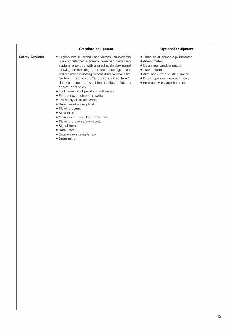
Standard equipment Optional equipment
Safety Devices ¡English WYLIE brand Load Moment Indicator; thisis a computerized automatic over-load preventingsystem; provided with a graphic display panelallowing the inputting of the cranes configuration,and a function indicating present lifting conditions like“actual lifted load”, “allowable rated load”,“boom length”, “working radius”, “boomangle”, and so on;
¡Lock lever (Fool proof shut-off lever);¡Emergency engine stop switch;¡LMI safety circuit-off switch;¡Hook over-hoisting limiter;¡Slewing alarm;¡Slew lock;¡Main crane hoist drum pawl lock;¡Slewing brake safety circuit;¡Signal horn;¡Hook latch;¡Engine monitoring lamps;¡Drum mirror.
¡Three color percentage indicator;¡Anemometer;¡Cabin roof window guard;¡Travel alarm;¡Aux. hook over-hoisting limiter;¡Drum rope over-payout limiter;¡Emergeacy escape hammer.

• We are constantly improving our products and therefore reserve the right to change designs and specifications without notice.• Units in this specification are shown under International System of Units; the figures in parenthesis are under GravitationalSystem of Units as old one.
Address Inquires to:
SCX400T
Printed in Japan1104(A)05H.EA173
(Supersedes 0702(A)02T.EA101)