Embed Size (px)
Citation preview

The Formwork Experts
12/2012
en-GB999805402
User informationMethod statement
Bridge formwork ParaTop
98054-218-02

2 999805402 - 12/2012
Introduction User information Bridge formwork ParaTop
The Formwork Experts
Introduc-tion
© by Doka Industrie GmbH, A-3300 Amstetten

User information Bridge formwork ParaTop Introduction
3999805402 - 12/2012
The Formwork Experts
Contents4 Introduction4 Elementary safety warnings6 Eurocodes at Doka8 Doka services
10 System description11 System overview
12 Structural design
17 Assembly instructions17 Pre-assembling the Top 50 platform20 Anchoring on the structure23 Starting up
26 Dismantling
27 General remarks27 Design variants30 Fall-arrest systems on the structure31 Transporting, stacking and storing
35 Component overview

4 999805402 - 12/2012
Introduction User information Bridge formwork ParaTop
The Formwork Experts
IntroductionElementary safety warnings
User target groups● This manual is aimed at all persons who will be work-
ing with the Doka product or system that it describes. It contains information on the standard design for setting up this system, and on correct, compliant uti-lisation of the system.
● All persons working with the product described herein must be familiar with the contents of this man-ual and with all the safety instructions it contains.
● Persons who are incapable of reading and under-standing this booklet, or who can do so only with dif-ficulty, must be instructed and trained by the cus-tomer.
● The customer is to ensure that the information mate-rials provided by Doka (e.g. User Information book-lets, Instructions for Assembly and Use, Operating Instruction manuals, plans etc.) are available to all users, and that they have been made aware of them and have easy access to them at the usage location.
● In the relevant technical documentation and form-work utilisation plans, Doka shows the workplace safety precautions that are necessary in order to use the Doka products safely in the usage situations shown. In all cases, users are obliged to ensure compliance with national OH&S (occupational health and safety) rules throughout the entire project and to take appro-priate additional or alternative workplace safety pre-cautions where necessary.
Hazard assessment● The customer is responsible for drawing up, docu-
menting, implementing and continually updating a hazard assessment at every job-site.This document serves as the basis for the site-spe-cific hazard assessment, and for the instructions given to users on how to prepare and utilise the sys-tem. It does not substitute for these, however.
Remarks on this document● This manual can also be used as a generic method
statement or incorporated with a site-specific method statement.
● Many of the illustrations in this booklet show the situation during formwork assembly and are therefore not always complete from the safety point of view.Any safety accessories not shown in these illustra-tions must still be used by the customer, in accord-ance with the applicable rules and regulations.
● Further safety instructions, especially warnings, will be found in the individual sections of this document!
Planning● Provide safe workplaces for those using the form-
work (e.g. for when it is being erected/dismantled, modified or repositioned etc). It must be possible to get to and from these workplaces via safe access routes!
● If you are considering any deviation from the details and instructions given in this booklet, or any application which goes beyond those described in the booklet, then revised static cal-culations must be produced for checking, as well as supplementary assembly instructions.
Rules applying during all phases of the assignment:● The customer must ensure that this product is
erected and dismantled, reset and generally used for its intended purpose under the direction and super-vision of suitably skilled persons with the authority to issue instructions.These persons' mental and physical capacity must not in any way be impaired by alcohol, medicines or drugs.
● Doka products are technical working appliances which are intended for industrial/commercial use only, always in accordance with the respective Doka User Information booklets or other technical docu-mentation authored by Doka.
● The stability of all components and units must be ensured during all phases of the construction work!
● The functional/technical instructions, safety warn-ings and loading data must all be strictly observed and complied with. Failure to do so can cause acci-dents and severe (even life-threatening) damage to health, as well as very great material damage.
● Fire-sources are not permitted anywhere near the formwork. Heating appliances are only allowed if properly and expertly used, and set up a safe dis-tance away from the formwork.
● The work must take account of the weather condi-tions (e.g. risk of slippage). In extreme weather, steps must be taken in good time to safeguard the equipment, and the immediate vicinity of the equip-ment, and to protect employees.
● All connections must be checked regularly to ensure that they still fit properly and are functioning cor-rectly.It is very important to check all screw-type connec-tions and wedge-clamped joins whenever the con-struction operations require (particularly after excep-tional events such as storms), and to tighten them if necessary.

User information Bridge formwork ParaTop Introduction
5999805402 - 12/2012
The Formwork Experts
Assembly● The equipment/system must be inspected by the
customer before use, to ensure that it is in suitable condition. Steps must be taken to rule out the use of any components that are damaged, deformed, or weakened due to wear, corrosion or rot.
● Combining our formwork systems with those of other manufacturers could be dangerous, risking damage to both health and property. If you intend to combine different systems, please contact Doka for advice first.
● The assembly work must be carried out by suitably qualified employees of the client's.
● It is not permitted to modify Doka products; any such modifications constitute a safety risk.
Erecting the formwork● Doka products and systems must be set up in such
a way that all loads acting upon them are safely transferred!
Pouring● Do not exceed the permitted fresh-concrete pres-
sures. Excessively high pouring rates lead to form-work overload, cause greater deflection and risk causing breakage.
Striking the formwork● Do not strike the formwork until the concrete has
reached sufficient strength and the person in charge has given the order for the formwork to be struck!
● When striking the formwork, never use the crane to break concrete cohesion. Use suitable tools such as timber wedges, special pry-bars or system features such as Framax stripping corners.
● When striking the formwork, do not endanger the stability of any part of the structure, or of any scaf-folding, platforms or formwork that is still in place!
Transporting, stacking and storing● Observe all regulations applying to the handling of
formwork and scaffolding. In addition, the Doka slinging means must be used - this is a mandatory requirement.
● Remove any loose parts or fix them in place so that they cannot be dislodged or fall free!
● All components must be stored safely, following all the special Doka instructions given in the relevant sections of this manual!
Regulations; industrial safety● Always observe all industrial safety regulations and
other safety rules applying to the application and uti-lisation of our products in the country and/or region in which you are operating.
● If a person or object falls against, or into, the side-guard component and/or any of its accessories, the component affected may only continue in use after it has been inspected and passed by an expert.
Maintenance● Only original Doka components may be used as
spare parts. Repairs may only be carried out by the manufacturer or authorised facilities.
Symbols usedThe following symbols are used in this booklet:
MiscellaneousWe reserve the right to make alterations in the interests of technical progress.
Important noteFailure to observe this may lead to malfunc-tion or damage.
CAUTION / WARNING / DANGERFailure to observe this may lead to material damage, and to injury to health which may range up to the severe or even life-threaten-ing.
InstructionThis symbol indicates that actions need to be taken by the user.
Sight-checkIndicates that you need to do a sight-check to make sure that necessary actions have been carried out.
TipPoints out useful practical tips.
ReferenceRefers to other documents and materials.
☞

6 999805402 - 12/2012
Introduction User information Bridge formwork ParaTop
The Formwork Experts
Eurocodes at DokaIn Europe, a uniform series of Standards known as Eurocodes (EC) was developed for the construction field by the end of 2007. These are intended to provide a uniform basis, valid throughout Europe, for product specifications, tenders and mathematical verification.The EC are the world's most highly developed Stand-ards in the construction field.In the Doka Group, the EC are to be used as standard from the end of 2008. They will thus supersede the DIN norms as the "Doka standard" for product design.
The widely used "Permissible stress design" (compar-ing the actual stresses with the permissible stresses) has been superseded by a new safety concept in the EC.The EC contrast the actions (loads) with the resistance (capacity). The previous safety factor in the permissible stresses is now divided into several partial factors. The safety level remains the same!
Comparison of the safety concepts (example)
Ed Design value of effect of actions(E ... effect; d ... design)Internal forces from action Fd(VEd, NEd, MEd)
Rd Design value of the resistance(R ... resistance; d ... design)Design capacity of cross-section(VRd, NRd, MRd)
Fd Design value of an actionSteel: Rd =
RkTimber: Rd = kmod ·
Rk
Fd = F · Fk M M
(F ... force)Fk Characteristic value of an action
"actual load", service load(k ... characteristic)e.g. dead weight, live load, concrete pressure, wind
Rk Characteristic value of the resistancee.g. moment resistance to yield stress
F Partial factor for actions(in terms of load; F ... force)e.g. for dead weight, live load, concrete pres-sure, windValues from EN 12812
M Partial factor for a material property(in terms of material; M...material)e.g. for steel or timberValues from EN 12812
kmod Modification factor (only for timber – to take account of the moisture and the duration of load action)e.g. for Doka beam H20Values as given in EN 1995-1-1 and EN 13377
Ed
Rd
Permissible stress design EC/DIN concept
Factual Fpermissible Ed Rd
A Utilisation factor
60 [kN]
60<70 [kN]
115.5 [kN]
� ~ 1.65
Fyield
Fpermissible
Factual
9801
3-10
0
A
90 [kN]
115.5 [kN]
90<105 [kN]
Rk
Rd
Ed
�M
= 1.1
�F
= 1.5
9801
3-10
2
A
The "permissible values" communicated in Doka documents (e.g.: Qpermissible = 70 kN) do not correspond to the design values (e.g.: VRd = 105 kN)!➤ Avoid any confusion between the two!➤ Our documents will continue to state the per-
missible values.
Allowance has been made for the following par-tial factors:F = 1.5M, timber = 1.3M, steel = 1.1kmod = 0.9
In this way, all the design values needed in an EC design calculation can be ascertained from the permissible values.

User information Bridge formwork ParaTop Introduction
7999805402 - 12/2012
The Formwork Experts

8 999805402 - 12/2012
Introduction User information Bridge formwork ParaTop
The Formwork Experts
Doka services
Support in every stage of the projectDoka offers a broad spectrum of services, all with a sin-gle aim: to help you succeed on the site.Every project is unique. Nevertheless, there is one thing that all construction projects have in common – and that is a basic structure with five stages. We at Doka know our clients' varying requirements. With our consulting, planning and other services, we help you achieve effective implementation of your formwork assignment using our formwork products – in every one of these stages.
Project Development Stage Bidding Stage Project Management Planning Stage
Taking well-founded decisionsthanks to professional advice and consulting
Optimising the preliminary workwith Doka as an experienced part-ner
Controlled, regular forming oper-ations, for greater efficiencyresulting from realistically calculated formwork concepts
Find precisely the right formwork solutions, with the aid of● help with the bid invitation● in-depth analysis of the initial sit-
uation● objective evaluation of the plan-
ning, execution, and time-risks
Draw up potentially winning bids, by● basing them on realistically calcu-
lated guideline prices● making the right formwork
choices● having an optimum time-calcula-
tion basis
Plan cost-effectively right from the outset, thanks to● detailed offers● determination of the commission-
ing quantities● co-ordination of lead-times and
handover deadlines
1 2 3

User information Bridge formwork ParaTop Introduction
9999805402 - 12/2012
The Formwork Experts
The advantages for youthanks to professional advice and consulting
● Cost savings and time gainsWhen we advise and support you right from the word "go", we can make sure that the right formwork systems are chosen and then used as planned. This lets you achieve optimum utilisation of the formwork equipment, and effec-tive forming operations because your workflows will be correct.
● Maximised workplace safetyThe advice and support we can give you in how to use the equip-ment correctly, and as planned, leads to greater safety on the job.
● TransparencyBecause our services and costs are completely transparent, there is no need for improvisation dur-ing the project – and no unpleas-ant surprises at the end of it.
● Reduced close-out costsOur professional advice on the selection, quality and correct use of the equipment helps you avoid damage, and minimise wear-and-tear.
Concrete Construction Stage Project Close-out Stage
Optimum resource utilisationwith assistance from the Doka Formwork Experts
Seeing things through to a posi-tive conclusionwith professional support
Workflow optimisation, thanks to● thorough utilisation planning● internationally experienced pro-
ject technicians● appropriate transport logistics● on-site support
Doka Services are a byword for transparency and efficiency here, offering● jointly handled return of rented
formwork● professional dismantling● efficient cleaning and recondition-
ing using special equipment
4 5

10 999805402 - 12/2012
System description User information Bridge formwork ParaTop
The Formwork Experts
System descriptionSystem description
Bridge formwork ParaTop -for cost-efficient, safe forming of cantilever slabsBridge formwork ParaTop is a modular formwork sys-tem for use on steel composite bridges and pre-cast concrete bridges. The operations needed for erecting and aligning the formwork, reinforcing, pouring and striking can all be performed directly from the bridge superstructure.
Great flexibility for a broad spectrum of utilisation
● Can be used on both pre-cast concrete members and steel girders
● Modular design concept makes it easy to adapt to many different cross-sections of cantilever slab
Highly cost-efficient
● Less equipment and labour needed, thanks to the large influence widths of the brackets
● Bolted connections for fast, accurate assembly / pre-assembly
● Utilises re-usable Top 50 system components
High safety
● Any type of side protection is possible, from scaffold tubes to guard-rail boards to full-area enclosures
● No need to access the underside of the formwork, as it can be operated from above
● The open design of the ParaTop insert-shoes allows the pre-assembled Top 50 platforms to be hung into place very quickly

User information Bridge formwork ParaTop System description
11999805402 - 12/2012
The Formwork Experts
System overviewUsed on steel girders
Used on pre-cast concrete members
The ParaTop insert-shoe allows an anchor angle of 41°-55°. ParaTop insert-cones are available in 2 differ-ent lengths for various thicknesses of slab. The maxi-mum possible slab thicknesses depend upon the anchor angle.
b ... max. slab thickness
Note:The axis of the anchor is measured from the centre of the curved section of the ParaTop insert-shoe.
a ... 113 mm
A ParaTop insert-shoe - steel (expendable part)
B Threaded stud (expendable part)
D Eye-lug anchor 15.0 without tie-rod
E Tie-rod 15.0mm
F Plastic tube 22mm (expendable part)
G ParaTop insert-channel U65 (expendable part)
H ParaTop insert-cone
I Split nut SL-1 15.0
J Hexagon nut 15.0
A ParaTop insert-shoe - concrete (expendable part)
C Anchor-bolt (expendable part)
D Eye-lug anchor 15.0 without tie-rod
E Tie-rod 15.0mm
F Plastic tube 22mm (expendable part)
G ParaTop insert-channel U65 (expendable part)
H ParaTop insert-cone
I Split nut SL-1 15.0
J Hexagon nut 15.0
98054-215-01
F
E
D
G
H
I
J
A
B
98054-216-01
E
F
G
H
I
J
AD
C
... anchor angle
41° 45° 55°
ParaTop insert-cone 0.35m
310 mm 325 mm 360 mm
ParaTop insert-cone 0.65m
500 mm 525 mm 600 mm
... anchor angle 41° ... anchor angle 55°
98054-237-01
�
b
98054-237-03
�
b98054-237-04
a
a

12 999805402 - 12/2012
Structural design User information Bridge formwork ParaTop
The Formwork Experts
Structural designStructural design
The following load situations must be allowed for:● live load only● full load● storm winds (without live load)
Note:Smaller anchor angles lead to higher anchor loads.
☞ Important note:
● The structural design shown here only applies if the load centre is situated inside the zone marked "A".
● The Top 50 system components (Multi-pur-pose walings WS10, spindle struts) and the railings must be verified for each project sep-arately.
A Permitted zone for the load centre
B Ballast weight
CAUTIONThere is a risk of the formwork tipping over in high winds.➤ Check whether a ballast weight is needed to
secure the Top 50 platform in storm winds.
98054-216-01
A
98054-239-01
B
What to do if the load centre is situated outside Zone "A":
● Provide a vertical support that the Top 50 platform can be braced against.
● Consult with the responsible Statical Calculation Dept. at Doka to determine the project-specific anchor load.
It is possible to enlarge Zone "A" by using a smaller anchor angle.
C Vertical support
If possible, also provide vertical supports on platforms where the load centre is situated inside Zone "A".
This makes it easier to pull tight the joint between the main beam and the Top 50 plat-form.
98054-215-01
V
C
98054-238-01
A
User information Bridge formwork ParaTop Structural design
13999805402 - 12/2012
The Formwork Experts

14 999805402 - 12/2012
Structural design User information Bridge formwork ParaTop
The Formwork Experts
Determining the anchoring forces
➤ Determine the vertical load.➤ Determine the factor, as a function of the anchor
angle.
If an intermediate value is obtained, the factor for the smaller anchor angle should be chosen.
➤ Determine the anchor load.Anchor load "T" = vertical load x factor
... 41° - 55°
➤ Depending on the anchor load, use the relevant curve (A) to (I) in the "Diagrams for determining the anchoring forces on the ParaTop insert-shoe".
Note:When using threaded studs, the permitted horizontal load is limited to 45 kN.Necessary precondition:The component to which the studs are welded must be made of min. S 355-grade steel.
➤ Determine the anchoring forces H, V2 and V1 from the "Diagrams for determining the anchoring forces".
... 41° - 55°
Example
● Basic data:- Curve (G) (anchor load = 60 kN)- anchor angle: 47.5°
● Result:- H = 41 kN- V2 = 34 kN- V1 = 78 kN
☞ Important note:
The structural design shown here only applies if the load centre is situated inside Zone "A" (see the section headed "Structural design").
... anchor angle Factor
41.00° 1.52
42.50° 1.48
43.75° 1.45
45.00° 1.41
46.25° 1.38
47.50° 1.36
48.75° 1.33
50.00° 1.31
51.25° 1.28
52.50° 1.26
53.75° 1.24
55.00° 1.22
98054-204-01
T
�
Anchor load [kN]
30 35 40 45 50 55 60 65 70
Curve (A) (B) (C) (D) (E) (F) (G) (H) (I)
T ... permitted anchor load: 70 kN
98054-204-01
V1V2
HT
�

User information Bridge formwork ParaTop Structural design
15999805402 - 12/2012
The Formwork Experts
Diagrams for determining the anchoring forces on the ParaTop insert-shoe
ParaTop insert-shoe H
H [kN]
Anchor angle in °
41 42.5 45 47.5 50 52.5 55
55
50
45
40
35
30
25
20
15
A
B
C
D
E
F
G
H
I
J
9805
4-10
2
J Permitted horizontal load for threaded studs: max. 45 kN(e.g. KÖCO RD M24 60 strength-grade 4.8)
ParaTop insert-shoe V2
V2 [kN]
Anchor angle in °
41 42.5 45 47.5 50 52.5 55
55
50
45
40
35
30
25
20
15
10
A
B
C
D
E
F
G
H
I
9805
4-10
1
ParaTop insert-shoe V1
V1 [kN]
Anchor angle in °
41 42.5 45 47.5 50 52.5 55
100
90
80
70
60
50
40
30
A
B
C
D
E
F
G
H
I
9805
3-10
0

16 999805402 - 12/2012
Structural design User information Bridge formwork ParaTop
The Formwork Experts
Max. influence width per handrail-post upright
Handrail post T 1.80m Universal railing SK 2.00mMulti-purpose waling WS 10 with Corner connect-
ing plate SK
Guard-rail board Scaffold tube Guard-rail boardFull-area enclo-
sureFull-area enclosure
Dyn
amic
pre
ssur
e q
(ze
)
Height of guard-rail boards: Height of guard-rail boards:
15 cm 20 cm 15 cm 20 cm
1.1 kN/m2 1.83 m 1.33 m 5.0 m 3.5 m 3.1 m 1.3 m 3.5 m
1.3 kN/m2 1.55 m 1.13 m 5.0 m 3.4 m 2.6 m 1.1 m 3.0 m
1.7 kN/m2 1.18 m 0.86 m 5.0 m 2.6 m 2.0 m 0.8 m 2.3 m
A Handrail post T 1.80m
B Universal railing SK 2.00m
C Multi-purpose waling WS10 Top50 2.25m
D Corner connecting plate SK
E Connecting pin 10cm + Spring cotter 5mm
9805
4-23
0-01
A
E
9805
4-23
4-01
B
E 9805
4-23
3-01
B
E 9805
4-23
5-01
B
E
9805
4-23
6-01
C
E D

User information Bridge formwork ParaTop Assembly instructions
17999805402 - 12/2012
The Formwork Experts
Assembly instructionsPre-assembling the Top 50 platform➤ Lay down Multi-purpose walings WS10, spaced
apart by the exact centre-to-centre distance.
a ... centre-to-centre spacing (tolerance max. ±5 mm)x = y ... diagonals (tolerance max. ±10 mm)
➤ Use squared timbers to adapt the Top 50 platform to the steel girder.
➤ Mount Doka beams H20 and squared timbers to the Multipurpose walings WS10.
➤ Fasten formwork sheets to the Doka beams with uni-versal countersunk screws 6x60.
A Multi-purpose waling WS10 Top50
B Doka beam H20
C Squared timbers
C Squared timbers
Alternatively, Doka H16 beams can be used.
D Doka beam H16
E Washer 5mm
98054-223-01
y x
a
A
B
C
98054-215-01
C
98054-251-01
D
E
B Doka beam H20
C Squared timbers
D Flange-clamp H20
E Flange claw
Do a sight-check to make sure that the form-work sheets have been fixed properly!
The sheet-covered area must be slightly shorter than the overall width of the platform.
The gap between two Top 50 platforms can later be closed with a fitting-board.
b ... approx. 100 mm
98054-223-02
BC
DE
98054-222-01
98054-241-01
b

18 999805402 - 12/2012
Assembly instructions User information Bridge formwork ParaTop
The Formwork Experts
➤ Bolt the Universal railings into the Multipurpose wal-ings WS10 with Connecting pins 10cm and secure these with Spring cotters 5mm.
➤ Fasten guard-rail boards to the Universal railings SK 2.00m.
➤ Place the Top 50 platform on a temporary support.➤ Bolt a 'Formwork element connector' to the vertical
Multi-purpose waling WS10 with Connecting pins 10cm, and secure these with Spring cotters 5mm.
➤ Bolt the spindle strut to the Multipurpose walings WS10 with Connecting pins 10cm, and secure these with Spring cotters 5mm.
➤ Adjust the spindle strut to the length shown in the shop drawing / assembly plan.
➤ Mount Doka beams H20 to the vertical Multi-purpose walings WS10.
➤ Brace the vertical Multi-purpose walings in the hori-zontal and the diagonal.
Distance between screw-on coupler and swivel cou-pler: max. 160 mm.
F Universal railing SK 2.00m
G Connecting pin 10cm + Spring cotter 5mm
98054-233-02
F
G G
98054-221-01
H Multi-purpose waling WS10 Top50
I Formwork element connector FF20/50 Z
J Spindle strut T7
K Doka beam H20
L Scaffolding tube 48.3mm (horizontal)
M Screw-on coupler 48mm 50
N Scaffolding tube 48.3mm (diagonal)
O Swivel coupler 48mm
98054-220-01
H
I
JK
98054-231-01
L
M
N
O

User information Bridge formwork ParaTop Assembly instructions
19999805402 - 12/2012
The Formwork Experts
➤ Screw the tie-rod all the way into the eye-lug anchor.➤ Bolt the eye-lug anchor to the Multi-purpose waling
with a Connecting pin 10cm and secure this with a Spring cotter 5mm (position as shown in shop draw-ing / assembly plan).
➤ Cut a plastic tube to length at the angle shown in the shop drawing / assembly plan.The ParaTop insert-cone is drilled open down to a depth of 45 mm so that the plastic tube can be inserted.The plastic tube must push up against the bottom of this drilled opening, so that its other end is pressed down tightly against the form-facing during assem-bly.
➤ Push the plastic tube onto the tie-rod.
a, b... project-specificc ... 45 mm
➤ Push the ParaTop insert-channel onto the tie-rod.➤ Push the ParaTop insert-cone onto the tie-rod.➤ Screw the Split nut SL-1 and the hexagon nut onto
the tie-rod.
c ... min. 120 mm
P Eye-lug anchor 15.0 without tie-rod
Q Tie-rod 15.0mm
The tie-rod must be resting against the Con-necting pin.
98054-219-02
PQ
98054-240-01
P
Q
R Plastic tube 22mm
T ParaTop insert-cone 0.35m
S ParaTop insert-channel U65 (expendable part)
T ParaTop insert-cone 0.35m
U Split nut SL-1 15.0
V Hexagon nut 15.0
98054-215-02
T
R
b
c a
98054-224-02
c
S
T
U
V

20 999805402 - 12/2012
Assembly instructions User information Bridge formwork ParaTop
The Formwork Experts
Anchoring on the structure
Used on steel girders"ParaTop insert-shoes - steel" are used for suspending Top 50 platforms from steel girders.
➤ The introduction of the forces, onward transfer of these forces within the structure, and the stability of the overall construction, must all be verified by the structural designer.
Necessary preconditionTo fix the ParaTop insert-shoes to steel girders, threaded studs are needed.Ideally, these studs will already have been welded on by the manufacturer of the steelwork decking, together with the head bolts. This speeds up the workflow on the site.➤ Plan this, and the delivery times, sufficiently far in
advance.
How to attach:➤ Bolt the "ParaTop insert-shoe - steel" onto the
threaded stud.
a ... 175 mmb ... 24 mmc ... min. 60 mm
Required fixing materials (expendable parts)● Washer 24● Hexagon nut M24
Note:Use only threaded studs of size M24.Minimum length: 60 mmIn order to weld the threaded stud on properly, a ceramic ferrule is required that is consumed during the welding-on operation.(This item is included with the threaded stud by the sup-pliers KÖCO - Köster & Co. GmbH.)For more details on fixing the threaded stud to the structural steelwork, please contact the Composite Bridge Competence Centre.
Welding the "ParaTop insert-shoes - steel" on directly
Note:In principle, it is possible to weld the "ParaTop insert-shoes - steel" directly onto the girder (e.g. if the threaded stud would not have sufficient load-bearing capacity).Steel-grade of ParaTop insert-shoes: S355
➤ In these cases, you should discuss the assembly procedure with your Doka technician.
☞ Important note:
Do not confuse the "ParaTop insert-shoe - steel" with the "ParaTop insert-shoe - con-crete"!
Distinguishing features of "ParaTop insert-shoes - steel":● gap between anchor-plate and steel girder● diam. 26 mm hole in anchor-plate
A ParaTop insert-shoe - steel
B Threaded stud (e.g. KÖCO RD M24 60 strength-grade 4.8, Art.n° 003-0524-001)
Determine the required load-bearing capacity of the threaded studs separately for each project!
Follow the manufacturer's applicable fitting instruc-tions.
CAUTION
➤ Observe all the standards and regulations applying to on-site welding work!
98054-204-01
A
B
a
b
c

User information Bridge formwork ParaTop Assembly instructions
21999805402 - 12/2012
The Formwork Experts
Used on pre-cast concrete members"ParaTop insert-shoes - concrete" are used for sus-pending Top 50 platforms from pre-cast concrete gird-ers.
➤ The introduction of the forces, onward transfer of these forces within the structure, and the stability of the overall construction, must all be verified by the structural designer.
How to attach:➤ Anchor the "ParaTop insert-shoe - concrete" to the
pre-cast concrete member.
a ... 175 mmb ... 20 mm
Note:Allow for the anchor-bolt diameter of 20 mm.Because the load-bearing capacity of the anchor-bolt on pre-cast concrete members is lower than that of the threaded stud on structural steelwork, the load-bearing capacity of the suspension point is also lower.
☞ Important note:
Do not confuse the "ParaTop insert-shoe - con-crete" with the "ParaTop insert-shoe - steel"!
Distinguishing features of "ParaTop insert-shoes - concrete":● Anchor plate rests directly on the concrete● diam. 22 mm hole in anchor-plate
A ParaTop insert-shoe - concrete
B Anchor-bolt (e.g. Hilti HIT-HY 150 chemical anchor + HAS-E (8.8)-M20 anchor-rod orFischer RG M20x330 E (8.8)
Determine the required load-bearing capacity of the anchor-bolts separately for each project!
Follow the manufacturer's applicable fitting instruc-tions.
98054-205-01
a
b
A
B

22 999805402 - 12/2012
Assembly instructions User information Bridge formwork ParaTop
The Formwork Experts
Used on CIP concreteOn cracked concretes of medium strength, it is advisa-ble to fasten the ParaTop insert-shoe to embedded suspension points. There are several possible ways of preparing these suspension points. The method to be used should be agreed with the client/structural designer, before bid submission whenever possible, as the method used will directly affect the possible centre-distances of the brackets.
Variant 1: Fastened with ordinary anchor-plateThe position of the anchor-plate may vary depending on individual project requirements.
Variant 2: Fastened with site-provided anchor-plate with reinforcement (only for massive components)The position of the anchor-plate may vary depending on individual project requirements.
The design calculation for the anchor-plate is done by the anchor-plate manufacturer!
Follow the manufacturer's applicable fitting instruc-tions.
A ParaTop insert-shoe - concrete (welded onto anchor plate)
B Anchor plate (e.g. Peikko fastening plate: 200x200x20mm, S355 3xJPL studs 16x150mm)
98054-243-01
a
A
B
The design calculation for the anchor-plate is done by the anchor-plate manufacturer!
Follow the manufacturer's applicable fitting instruc-tions.
A ParaTop insert-shoe - concrete (welded onto anchor plate)
B Special anchor-plate with:C ReinforcementD Shear stud
98054-244-01
a
A
C
D
B

User information Bridge formwork ParaTop Assembly instructions
23999805402 - 12/2012
The Formwork Experts
Starting upThe modular design of the "Bridge formwork ParaTop" system means that many different combinations are possible.Depending on the project, the actual design may thus differ very greatly from the basic type described here.➤ In these cases, you should discuss the assembly
procedure with your Doka technician.➤ Follow the shop drawing / assembly plan exactly.
Fixing the Top 50 platform to the insert-shoes
General instructions on repositioning
Mounting to the structure:➤ Attach the Top 50 platform to the crane with 4 lifting
slings➤ Secure the lifting slings so that they cannot slip off.
☞ Important note:
● A hard, flat, firm surface is needed!● Prepare a sufficiently large assembly area.● Tightening torque of the couplers for the
bracing tubes: 50 Nm● During all assembly and dismantling work on
the Bridge formwork ParaTop that is carried out on the structure itself, the operators must use fall-arrest equipment (e.g. the Doka per-sonal fall-arrest set).
☞ Important note:
● Before lifting: Remove any loose items from the formwork and platforms, or secure them firmly.
● "Passenger transportation" is forbidden!● Use lifting slings with sufficient carrying
capacity.● It is only possible to attach the lifting slings if
the Doka beams project sufficiently far beyond the sheet-covered area.
A Anti-slipoff protection for lifting-slings
98054-242-01
A A

24 999805402 - 12/2012
Assembly instructions User information Bridge formwork ParaTop
The Formwork Experts
➤ Fly the Top 50 platform to the ParaTop insert-shoes.
➤ Raise the insert-channel and fit it in place in the insert-shoe.
➤ Screw the Split nut SL-1 together completely, by hand.Overall length a = 90 mm
➤ Tighten the split nut with a size 30 combination wrench to pull the Top 50 platform towards the bridge superstructure.
Note:It is necessary to reduce the load on the bracket if upturn beams have to be cast on the cantilever slab in a 2nd pouring operation and the bracket has not been calculated for the whole concrete cross-section.
➤ Fix the 2nd anchor of the formwork unit in the same way.
➤ Detach the lifting chain from the Top 50 platform.
B ParaTop insert-channel U65
C ParaTop insert-shoe - steel
☞ ➤ Do not bend tie rods.
The insert-channel must snap into the insert-shoe without having to be forced.
98054-247-01
98054-228-01
B
C
1
2
98054-228-02
a
D Split nut SL-1 15.0
The Split nut SL-1 permits the following func-tions:● last-millimetre fine adjustment● reducing load on Top 50 platform
If these functions are not needed, the Split nut SL-1 15.0 can be replaced by a hexagon nut.
98054-213-02
D

User information Bridge formwork ParaTop Assembly instructions
25999805402 - 12/2012
The Formwork Experts
➤ When aligning and adjusting, fix the tie-rod with a "Spanner for tie-rod" to prevent it turning.
➤ Counter (lock) the Split nut SL-1 with a hexagon nut.➤ Make a coloured mark on the tie-rod.
This makes it easier to check that the anchoring components have been fitted correctly.
➤ Insert fitting-boards between the Top 50 platforms and fix these with nails if necessary.
➤ If necessary, place ballast weights on the Top 50 platforms to prevent them tipping over.
➤ Mount the stop-end formwork.➤ Spray the formwork sheets and insert-cones with
concrete release agent.➤ Place the reinforcement.
Pouring➤ Remove the ballast from the formwork construction,
if this is necessary for statical reasons.➤ Pour from the inside towards the outside.
Fine-adjusting the Top 50 platform:
Tighten the split nut with a size 41 combination wrench so as to tension the tie-rod. When doing this, hold the inside of the split nut with a size 30 combination wrench to prevent it turning.1 rotation = 1.5 mmTensioning distance max. 20 mm
98054-213-01
With reference to the coloured mark, check that the anchoring components have been fit-ted correctly.
Place a Sealing sleeve K over the Split nut SL-1 to protect it from soiling.
As soon as the concrete is strong enough to be walked on: Turn the anchoring cones clockwise by approx. 90°, to make it easier to remove them when the formwork is stripped.
98054-218-03
E
98054-218-04

26 999805402 - 12/2012
Dismantling User information Bridge formwork ParaTop
The Formwork Experts
DismantlingDismantlingThe Top 50 platform is dismounted using a transport fork.
➤ Widen the fork to safeguard the Top 50 platform against tipping over.
How far the fork needs to be widened will depend on the inter-bracket spacings, so is different for each project.
➤ Support the Top 50 platform with the transport fork.
➤ Loosen the check-nut and Split nut SL-1 and unscrew them from the tie-rod.The Top 50 platform is now resting on the transport fork.
➤ Remove the tie-rod with the "Spanner for tie-rod".➤ Lift the formwork construction away on the transport
fork, and set it down on the temporary support.
➤ Detach the insert-cone from the concrete.➤ The rest of the dismantling sequence is done at
ground level, in reverse order.
A Lifting extension bracket DF 1t
B Transport fork DF 1t/0.90m
Follow the directions in the 'Lifting extension bracket DF and Transport fork DF' Operating Instructions!
C Squared timber
D Doka beam H20
E Brace stirrup 8 + Anti-twisting plate for Brace stirrup 8
Follow the directions in the project-specific Operating Instructions for widened transport forks!
9210-200-01
A
B
98054-250-02
DE C
☞ Important note:
➤ When loosening the nuts, fix the tie-rod with a "Spanner for tie-rod".
98054-250-01
98054-220-01

User information Bridge formwork ParaTop General remarks
27999805402 - 12/2012
The Formwork Experts
General remarksDesign variants
Used on steel girders Used on pre-cast concrete members
Used on pre-cast concrete members
A ParaTop insert-channel U65 (expendable part)
B ParaTop insert-cone 0.35m
C ParaTop insert-shoe - steel (expendable part)
A ParaTop insert-channel U65 (expendable part)
B ParaTop insert-cone 0.35m
C ParaTop insert-shoe - steel (expendable part)
D Pre-cast member (retrofitted)
☞ Important note:
When creating the detailed final drawings for steel bridges, pay attention to the following places where snags may occur:● vertical transversal braces between the top
and bottom flanges● head bolts on the top of the flange (if their
position cannot be changed)● varying widths and thicknesses of flange
98054-227-01
AB C
98054-227-04
AB C
D
A ParaTop insert-channel U65 (expendable part)
B ParaTop insert-cone 0.35m
E ParaTop insert-shoe - concrete (expendable part)
A ParaTop insert-channel U65 (expendable part)
B ParaTop insert-cone 0.35m
E ParaTop insert-shoe - concrete (expendable part)
98054-227-05
AB E
98054-227-03
AB E

28 999805402 - 12/2012
General remarks User information Bridge formwork ParaTop
The Formwork Experts
Used between 2 steel girders
Situation after pouring
Formwork removal
Used between 2 downstand beams
A ParaTop insert-channel U65 (expendable part)
B ParaTop insert-cone 0.65m
C ParaTop insert-shoe - steel (expendable part)
D Eye-lug anchor 15.0 without tie-rod
E ParaTop insert-cone 0.35m as positioning-point for lowering the formwork by grip-hoist or winch (optional)
F Grip hoist (site-provided)
G WS10 frame (wheelable)
H Roller SL-1 D 200x50
A ParaTop insert-channel U65 (expendable part)
B ParaTop insert-cone 0.35m
C ParaTop special shoe (expendable part)
D Eye-lug tie-rod anchor NG
E ParaTop insert-cone 0.65m as positioning-point for lowering the formwork by winch (optional)
A
B
E
C
D
9805
4-25
2-01
H
G
F
9805
4-25
2-03
98054-254-02
A
B
C
D
E

User information Bridge formwork ParaTop General remarks
29999805402 - 12/2012
The Formwork Experts
Suspending brackets from 2 suspension shoesOn bridges with long cantilever arms, the high loads necessitate the use of 2 suspension shoes per bracket.
Examples
Cast-in-place bridge:● Cantilever forming traveller (CFT) in the typical zone● Bridge formwork ParaTop in the pier-head zone
Anchoring point (schematic top view)
Steel composite bridge with approach viaducts and arched or cable-stayed zones:● Composite forming carriage in the foreland zone● Bridge formwork ParaTop in the arched or cable-
stayed zones
A ParaTop insert-shoe - concrete (expendable part)
B Anchor plate
C Anchoring shoe (custom component)
D Multipurpose waling
E Anchoring shoe (custom component)
F Anchor plane
G Bracket plane
A
B
E
C D
98054-246-01
98054-249-01
A B
C
D
F G
A ParaTop insert-shoe - steel (expendable part)
C Anchoring shoe (custom component)
D Multipurpose waling
98054-248-01
A
C
D
98054-248-02
A
C D
30 999805402 - 12/2012
General remarks User information Bridge formwork ParaTop
The Formwork Experts
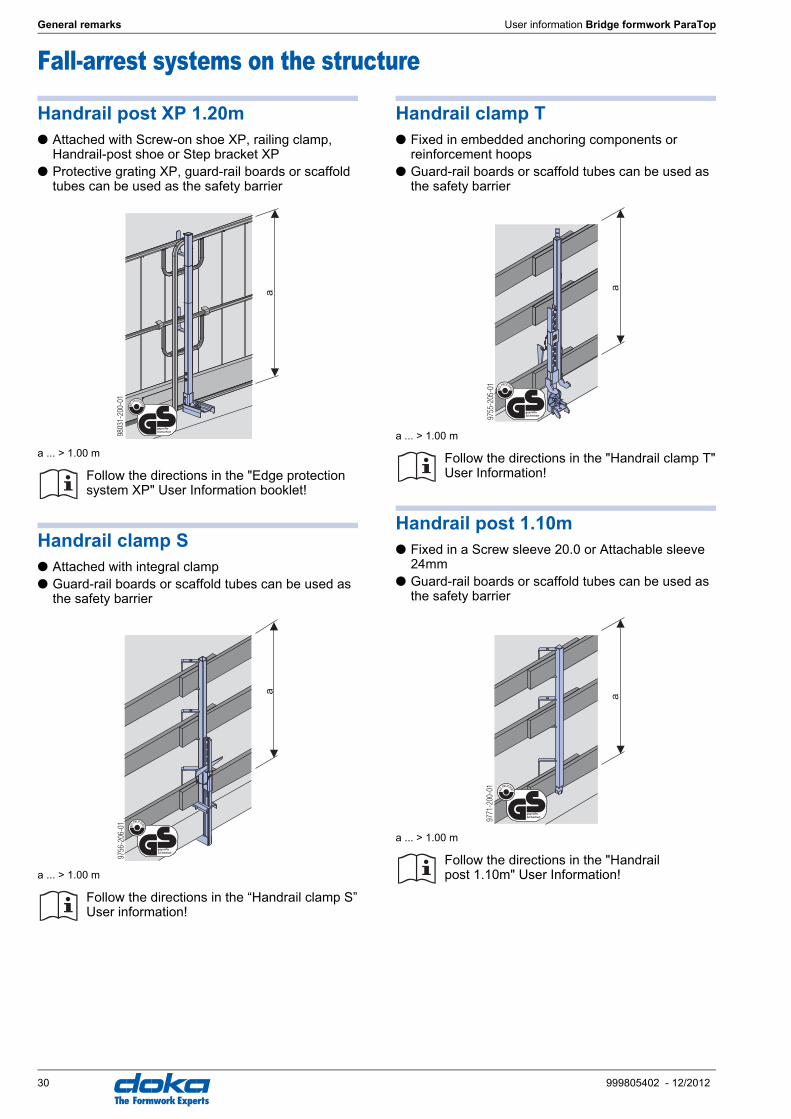
Fall-arrest systems on the structure
Handrail post XP 1.20m● Attached with Screw-on shoe XP, railing clamp,
Handrail-post shoe or Step bracket XP● Protective grating XP, guard-rail boards or scaffold
tubes can be used as the safety barrier
a ... > 1.00 m
Handrail clamp S● Attached with integral clamp● Guard-rail boards or scaffold tubes can be used as
the safety barrier
a ... > 1.00 m
Handrail clamp T● Fixed in embedded anchoring components or
reinforcement hoops● Guard-rail boards or scaffold tubes can be used as
the safety barrier
a ... > 1.00 m
Handrail post 1.10m● Fixed in a Screw sleeve 20.0 or Attachable sleeve
24mm● Guard-rail boards or scaffold tubes can be used as
the safety barrier
a ... > 1.00 m
Follow the directions in the "Edge protection system XP" User Information booklet!
Follow the directions in the “Handrail clamp S” User information!
9803
1-20
0-01
a
geprüfte
Sicherheit
9756
-206
-01
a
geprüfte
Sicherheit
Follow the directions in the "Handrail clamp T" User Information!
Follow the directions in the "Handrail post 1.10m" User Information!
9755
-205
-01
a
geprüfte
Sicherheit
9771
-200
-01
a
geprüfte
Sicherheit

User information Bridge formwork ParaTop General remarks
31999805402 - 12/2012
The Formwork Experts
Transporting, stacking and storing
Doka skeleton transport box 1.70x0.80m
Storage and transport devices for small items:● durable● stackable
Suitable transport appliances:● crane● pallet stacking truck● forklift truck
To make the "Doka skeleton transport box" easier to load and unload, one of its sidewalls can be opened.
Using Doka skeleton transport boxes 1.70x0.80m as storage units
Max. n° of boxes on top of one another
Using Doka skeleton transport boxes 1.70x0.80m as transport devices
Lifting by crane
Repositioning by forklift truck or pallet stacking truck
The forks can be inserted under either the broadside or the narrowside of the containers.
Utilise the benefits of Doka multi-trip packaging on your site.Multi-trip packaging such as containers, stacking pal-lets and skeleton transport boxes keep everything in place on the site, minimise time wasted searching for parts, and streamline the storage and transport of sys-tem components, small items and accessories.
Max. load: 700 kg
Permitted imposed load: 3150 kg
☞ ● Multi-trip packaging items that each contain very different loads must be stacked with the heaviest ones at the bottom and the lightest ones at the top!
● Rating plate must be in place and clearly leg-ible
Outdoors (on the site) Indoors
Floor gradient up to 3% Floor gradient up to 1%
2 5
It is not allowed to stack empty pallets on top of one another!
➤ Only lift the boxes when their sidewalls are closed!
☞ ● Multi-trip packaging items may only be lifted one at a time.
● Use a suitable lifting chain. (Do not exceed the permitted load capacity). e.g: Doka 4-part chain 3.20m.
● Spread-angle max. 30°!
9234-203-01

32 999805402 - 12/2012
General remarks User information Bridge formwork ParaTop
The Formwork Experts
Doka multi-trip transport box 1.20x0.80m galv.
Storage and transport devices for small items:● durable● stackable
Suitable transport appliances:● crane● pallet stacking truck● forklift truck
Multi-trip transport box partitionDifferent items in the Multi-trip transport box can be kept separate with the Multi-trip transport box partitions 1.20m or 0.80m.
Possible ways of dividing the box
Using Doka multi-trip transport boxes as storage units
Max. n° of boxes on top of one another
Using Doka multi-trip transport boxes as transport devices
Lifting by crane
Repositioning by forklift truck or pallet stacking truck
The forks can be inserted under either the broadside or the narrowside of the containers.
Max. load: 1500 kg
Permitted imposed load: 7900 kg
☞ ● Multi-trip packaging items that each contain very different loads must be stacked with the heaviest ones at the bottom and the lightest ones at the top!
● Rating plate must be in place and clearly leg-ible
A Slide-bolt for fixing the partition
Multi-trip transport box partition
Lengthways Crossways
1.20m max. 3 partitions -
0.80m - max. 3 partitions
Tr75
5-20
0-02
A
Tr755-200-04 Tr755-200-05
Outdoors (on the site) Indoors
Floor gradient up to 3% Floor gradient up to 1%
3 6
It is not allowed to stack empty pallets on top of one another!
☞ ● Multi-trip packaging items may only be lifted one at a time.
● Use a suitable lifting chain. (Do not exceed the permitted load capacity). e.g: Doka 4-part chain 3.20m.
● Spread-angle max. 30°!
9206-202-01

User information Bridge formwork ParaTop General remarks
33999805402 - 12/2012
The Formwork Experts
Doka stacking pallet 1.55x0.85m and 1.20x0.80mStorage and transport devices for long items:● durable● stackable
Suitable transport appliances:● crane● pallet stacking truck● forklift truck
The Bolt-on caster set B turns the stacking pallet into a fast and manoeuvrable transport trolley.
Using Doka stacking pallets as storage units
Max. n° of units on top of one another
Using Doka stacking pallets as transport devices
Lifting by crane
Repositioning by forklift truck or pallet stacking truck
Follow the directions in the "Bolt-on castor set B" Operating Instructions!
Max. load: 1100 kg
Permitted imposed load: 5900 kg
☞ ● Multi-trip packaging items that each contain very different loads must be stacked with the heaviest ones at the bottom and the lightest ones at the top!
● Rating plate must be in place and clearly leg-ible
Outdoors (on the site) Indoors
Floor gradient up to 3% Floor gradient up to 1%
2 6
It is not allowed to stack empty pallets on top of one another!
☞ ● How to use with bolt-on castor set:Always apply the fixing brake when the con-tainer is "parked".When Doka stacking pallets are stacked, the bottom pallet must NOT be one with a bolt-on caster set mounted to it.
☞ ● Multi-trip packaging items may only be lifted one at a time.
● Use a suitable lifting chain. (Do not exceed the permitted load capacity). e.g: Doka 4-part chain 3.20m.
● Load the items centrically.● Fasten the load to the stacking pallet so that
it cannot slide or tip out.● When lifting stacking pallets to which Bolt-on
castor sets B have been attached, you must also follow the directions in these Operating Instructions!
● Spread-angle max. 30°!
a
Doka stacking pallet 1.55x0.85m max. 4.0 m
Doka stacking pallet 1.20x0.80m max. 3.0 m
☞ ● Load the items centrically.● Fasten the load to the stacking pallet so that
it cannot slide or tip out.
92815-224-01
a
= =

34 999805402 - 12/2012
General remarks User information Bridge formwork ParaTop
The Formwork Experts
Doka accessory boxStorage and transport devices for small items:● durable● stackable
Suitable transport appliances:● crane● pallet stacking truck● forklift truck
The Doka accessory box is the tidy, easy-to-find way of storing and stacking all interconnection and form-tie components.The Bolt-on caster set B turns the stacking pallet into a fast and manoeuvrable transport trolley.
Doka accessory box as storage units
Max. n° of boxes on top of one another
Doka accessory box as transport devices
Lifting by crane
Repositioning by forklift truck or pallet stacking truck
The forks can be inserted under either the broadside or the narrowside of the containers.
Bolt-on castor set BThe Bolt-on caster set B turns the stacking pallet into a fast and manoeuvrable transport trolley.Suitable for drive-through access openings > 90 cm.
The Bolt-on caster set B can be mounted to the follow-ing multi-trip packaging items:● Doka accessory box● Doka stacking pallets
Follow the directions in the "Bolt-on castor set B" Operating Instructions!
Max. load: 1000 kg
Permitted imposed load: 5530 kg
☞ ● Multi-trip packaging items that each contain very different loads must be stacked with the heaviest ones at the bottom and the lightest ones at the top!
● Rating plate must be in place and clearly leg-ible
Outdoors (on the site) Indoors
Floor gradient up to 3% Floor gradient up to 1%
3 6
It is not allowed to stack empty pallets on top of one another!
☞ ● How to use with bolt-on castor set:Always apply the fixing brake when the con-tainer is "parked".When Doka accessory boxes are stacked, the bottom box must NOT be one with a bolt-on castor set mounted to it.
☞ ● Multi-trip packaging items may only be lifted one at a time.
● Use a suitable lifting chain. (Do not exceed the permitted load capacity). e.g: Doka 4-part chain 3.20m.
● When lifting stacking pallets to which Bolt-on castor sets B have been attached, you must also follow the directions in these Operating Instructions!
● Spread-angle max. 30°!
Follow the directions in the Operating Instruc-tions!
92816-206-01

Article n°[kg] Article n°[kg]
35999805402 - 12/2012
User information Bridge formwork ParaTop Component overview
The Formwork Experts
Component overviewDoka Load-bearing SystemsBridge formwork ParaTop
ParaTop insert-shoe concrete 3.1 584444000ParaTop-Einbauschuh Beton
ParaTop insert-shoe steel 3.1 584443000ParaTop-Einbauschuh Stahl
ParaTop insert-channel U65 0.89 584442000ParaTop-Einbauprofil U65
ParaTop insert-cone 0.35m 2.9 584441000ParaTop-Einbaukonus 0,35m
ParaTop insert-cone 0.65m 6.2 584447000ParaTop-Einbaukonus 0,65m
Eye-lug anchor 15.0 without tie rod 1.2 580649000Ösenanker 15,0 ohne Ankerstab
Tie rod 15.0mm galvanised 0.50m 0.72 581821000Tie rod 15.0mm galvanised 0.75m 1.1 581822000Tie rod 15.0mm galvanised 1.00m 1.4 581823000Tie rod 15.0mm galvanised 1.25m 1.8 581826000Tie rod 15.0mm galvanised 1.50m 2.2 581827000Tie rod 15.0mm galvanised 1.75m 2.5 581828000Tie rod 15.0mm galvanised 2.00m 2.9 581829000Tie rod 15.0mm galvanised 2.50m 3.6 581852000Tie rod 15.0mm galvanised .....m 1.4 581824000Tie rod 15.0mm non-treated 0.50m 0.73 581870000Tie rod 15.0mm non-treated 0.75m 1.1 581871000Tie rod 15.0mm non-treated 1.00m 1.4 581874000Tie rod 15.0mm non-treated 1.25m 1.8 581886000Tie rod 15.0mm non-treated 1.50m 2.1 581876000Tie rod 15.0mm non-treated 1.75m 2.5 581887000Tie rod 15.0mm non-treated 2.00m 2.9 581875000Tie rod 15.0mm non-treated 2.50m 3.6 581877000Tie rod 15.0mm non-treated 3.00m 4.3 581878000Tie rod 15.0mm non-treated 3.50m 5.0 581888000Tie rod 15.0mm non-treated 4.00m 5.7 581879000Tie rod 15.0mm non-treated 5.00m 7.2 581880000Tie rod 15.0mm non-treated 6.00m 8.6 581881000Tie rod 15.0mm non-treated 7.50m 10.7 581882000Tie rod 15.0mm non-treated .....m 1.4 581873000Ankerstab 15,0mm
Split nut SL-1 15.0 0.70 582835000Spannmutter SL-1 15,0
Hexagon nut 15.0 0.23 581964000Sechskantmutter 15,0
Sealing sleeve K 15.0 0.03 581976000Dichtungshülse K 15,0
Multi-purpose waling WS10 Top50 0.50m 10.2 580001000Multi-purpose waling WS10 Top50 0.75m 14.9 580002000Multi-purpose waling WS10 Top50 1.00m 19.6 580003000Multi-purpose waling WS10 Top50 1.25m 24.7 580004000Multi-purpose waling WS10 Top50 1.50m 29.7 580005000Multi-purpose waling WS10 Top50 1.75m 35.0 580006000Multi-purpose waling WS10 Top50 2.00m 38.9 580007000Multi-purpose waling WS10 Top50 2.25m 44.2 580008000Multi-purpose waling WS10 Top50 2.50m 48.7 580009000Multi-purpose waling WS10 Top50 2.75m 54.2 580010000Multi-purpose waling WS10 Top50 3.00m 60.2 580011000Multi-purpose waling WS10 Top50 3.50m 68.4 580012000Multi-purpose waling WS10 Top50 4.00m 79.4 580013000Multi-purpose waling WS10 Top50 4.50m 89.1 580014000Multi-purpose waling WS10 Top50 5.00m 102.0 580015000Multi-purpose waling WS10 Top50 5.50m 112.4 580016000Multi-purpose waling WS10 Top50 6.00m 118.0 580017000Mehrzweckriegel WS10 Top50
Non-treated
Non-treated
Non-treated
chrome-plated
Length: 36 cm
chrome-plated
Length: 66 cm
Galvanised
Length: 11 cm
Galvanised
Length: 9-11 cm
Width-across: 30/41 mm
Galvanised
Length: 5 cm
Width-across: 30 mm
Orange
Length: 12 cm
Diameter: 6 cm
Painted blue

Article n°[kg] Article n°[kg]
36 999805402 - 12/2012
Component overview User information Bridge formwork ParaTop
The Formwork Experts
Multi-purpose waling WU12 Top50 1.00m 25.3 580018000Multi-purpose waling WU12 Top50 1.25m 32.0 580019000Multi-purpose waling WU12 Top50 1.50m 37.5 580020000Multi-purpose waling WU12 Top50 1.75m 44.2 580021000Multi-purpose waling WU12 Top50 2.00m 50.0 580022000Multi-purpose waling WU12 Top50 2.50m 63.1 580023000Multi-purpose waling WU12 Top50 3.00m 75.7 580024000Multi-purpose waling WU12 Top50 3.50m 90.7 580025000Multi-purpose waling WU12 Top50 4.00m 103.4 580026000Mehrzweckriegel WU12 Top50
Formwork element connector FF20/50 Z 6.0 587533000Elementverbinder FF20/50 Z
Spindle strut T7 75/110cm 13.2 584308000Spindle strut T7 100/150cm 16.8 584309000Spindle strut T7 150/200cm 21.6 584324000Spindle strut T7 200/250cm 26.2 584325000Spindle strut T7 250/300cm 29.4 584326000Spindle strut T7 305/355cm 35.0 584327000Spindelstrebe T7
Connecting pin 10cm 0.34 580201000Verbindungsbolzen 10cm
Spring cotter 5mm 0.05 580204000Federvorstecker 5mm
Doka beam H20 eco P 1.80m 9.4 189940000Doka beam H20 eco P 2.45m 12.7 189936000Doka beam H20 eco P 2.65m 13.8 189937000Doka beam H20 eco P 2.90m 15.1 189930000Doka beam H20 eco P 3.30m 17.2 189941000Doka beam H20 eco P 3.60m 18.7 189942000Doka beam H20 eco P 3.90m 20.3 189931000Doka beam H20 eco P 4.50m 23.4 189943000Doka beam H20 eco P 4.90m 25.5 189932000Doka beam H20 eco P 5.90m 30.7 189955000Doka beam H20 eco P 9.00m 46.8 189956000Doka beam H20 eco P .....m 5.2 189999000Doka beam H20 eco P .....m BS 5.2 189957000Doka-Träger H20 eco P
Doka beam H20 eco P 1.25m 6.5 189939000Doka beam H20 eco P 12.00m 62.4 189993000Doka-Träger H20 eco P
Doka beam H20 eco N 1.80m 9.0 189283000Doka beam H20 eco N 2.45m 12.3 189271000Doka beam H20 eco N 2.65m 13.3 189272000Doka beam H20 eco N 2.90m 14.5 189273000Doka beam H20 eco N 3.30m 16.5 189284000Doka beam H20 eco N 3.60m 18.0 189285000Doka beam H20 eco N 3.90m 19.5 189276000Doka beam H20 eco N 4.50m 22.5 189286000Doka beam H20 eco N 4.90m 24.5 189277000Doka beam H20 eco N 5.90m 29.5 189287000Doka beam H20 eco N .....m 5.0 189299000Doka beam H20 eco N .....m BS 5.0 189289000Doka-Träger H20 eco N
Doka beam H20 eco N 1.25m 6.3 189282000Doka beam H20 eco N 12.00m 60.3 189288000Doka-Träger H20 eco N
Painted blue
Painted blue
Length: 55 cm
Galvanised
Galvanised
Length: 14 cm
Galvanised
Length: 13 cm
Varnished yellow
Varnished yellow
Varnished yellow
Varnished yellow

Article n°[kg] Article n°[kg]
37999805402 - 12/2012
User information Bridge formwork ParaTop Component overview
The Formwork Experts
Doka beam H20 top P 1.80m 9.9 189701000Doka beam H20 top P 2.45m 13.2 189702000Doka beam H20 top P 2.65m 14.3 189703000Doka beam H20 top P 2.90m 15.6 189704000Doka beam H20 top P 3.30m 17.7 189705000Doka beam H20 top P 3.60m 19.2 189706000Doka beam H20 top P 3.90m 20.8 189707000Doka beam H20 top P 4.50m 23.9 189708000Doka beam H20 top P 4.90m 26.0 189709000Doka beam H20 top P 5.90m 31.2 189710000Doka beam H20 top P .....m 5.4 189700000Doka beam H20 top P .....m BS 5.4 189711000Doka-Träger H20 top P
Doka beam H20 top N 1.80m 9.5 189011000Doka beam H20 top N 2.45m 12.8 189012000Doka beam H20 top N 2.65m 13.8 189013000Doka beam H20 top N 2.90m 15.0 189014000Doka beam H20 top N 3.30m 17.0 189015000Doka beam H20 top N 3.60m 18.5 189016000Doka beam H20 top N 3.90m 20.0 189017000Doka beam H20 top N 4.50m 23.0 189018000Doka beam H20 top N 4.90m 25.0 189019000Doka beam H20 top N 5.90m 30.0 189020000Doka beam H20 top N .....m 5.2 189010000Doka beam H20 top N .....m BS 5.2 189021000Doka-Träger H20 top N
Doka beam H16 P 1.80m 6.7 189969000Doka beam H16 P 2.45m 9.1 189961000Doka beam H16 P 2.90m 10.7 189962000Doka beam H16 P 3.30m 12.2 189963000Doka beam H16 P 3.90m 14.4 189966000Doka beam H16 P 4.90m 18.1 189967000Doka beam H16 P 9.00m 33.3 189970000Doka beam H16 P .....m 4.3 189960000Doka-Träger H16 P
Doka beam H16 N 1.80m 6.3 189851000Doka beam H16 N 2.45m 8.6 189802000Doka beam H16 N 2.90m 10.2 189803000Doka beam H16 N 3.30m 11.6 189807000Doka beam H16 N 3.90m 13.7 189805000Doka beam H16 N 4.90m 17.2 189813000Doka beam H16 N 9.00m 31.5 189852000Doka beam H16 N .....m 3.5 189850000Doka-Träger H16 N
Beam screw H 8/70 0.06 580117000Riegelverschraubung H 8/70
Doka formwork sheet 3-SO 21mm 100/50cm 5.3 186007000Doka formwork sheet 3-SO 21mm 150/50cm 7.9 186008000Doka formwork sheet 3-SO 21mm 200/50cm 10.5 186009000Doka formwork sheet 3-SO 21mm 250/50cm 13.1 186011000Doka formwork sheet 3-SO 21mm 300/50cm 15.8 186012000Doka formwork sheet 3-SO 21mm 350/50cm 18.4 186028000Doka formwork sheet 3-SO 21mm 400/50cm 21.0 186013000Doka formwork sheet 3-SO 21mm 450/50cm 23.6 186029000Doka formwork sheet 3-SO 21mm 500/50cm 26.3 186014000Doka formwork sheet 3-SO 21mm 550/50cm 28.9 186023000Doka formwork sheet 3-SO 21mm 600/50cm 31.5 186027000Doka formwork sheet 3-SO 21mm 100/100cm 10.5 186015000Doka formwork sheet 3-SO 21mm 150/100cm 15.8 186016000Doka formwork sheet 3-SO 21mm 200/100cm 21.0 186017000Doka formwork sheet 3-SO 21mm 250/100cm 26.3 186018000Doka formwork sheet 3-SO 21mm 300/100cm 31.5 186019000Doka formwork sheet 3-SO 21mm 350/100cm 36.8 186030000Doka formwork sheet 3-SO 21mm 400/100cm 42.0 186020000Doka formwork sheet 3-SO 21mm 450/100cm 47.3 186031000Doka formwork sheet 3-SO 21mm 500/100cm 52.5 186021000Doka formwork sheet 3-SO 21mm 550/100cm 57.8 186022000Doka formwork sheet 3-SO 21mm 600/100cm 63.0 186024000Doka formwork sheet 3-SO 21mm 250/125cm 32.8 186097000Doka formwork sheet 3-SO 21mm 300/150cm 47.3 186098000Doka formwork sheet 3-SO 21mm 600/150cm 94.5 186099000Doka formwork sheet 3-SO 21mm 150/50cm BS 7.9 186008100Doka formwork sheet 3-SO 21mm 200/50cm BS 10.5 186009100Doka formwork sheet 3-SO 21mm 250/50cm BS 13.1 186011100Doka formwork sheet 3-SO 21mm 300/50cm BS 15.8 186012100Doka-Schalungsplatte 3-SO 21mm
Doka formwork sheet 3-SO 27mm 100/50cm 6.5 187007000Doka formwork sheet 3-SO 27mm 150/50cm 9.8 187008000Doka formwork sheet 3-SO 27mm 200/50cm 13.0 187009000Doka formwork sheet 3-SO 27mm 250/50cm 16.3 187011000Doka formwork sheet 3-SO 27mm 300/50cm 19.5 187012000Doka formwork sheet 3-SO 27mm 350/50cm 22.8 187028000Doka formwork sheet 3-SO 27mm 400/50cm 26.0 187013000Doka formwork sheet 3-SO 27mm 450/50cm 29.3 187029000Doka formwork sheet 3-SO 27mm 500/50cm 32.5 187014000Doka formwork sheet 3-SO 27mm 550/50cm 35.8 187023000Doka formwork sheet 3-SO 27mm 600/50cm 39.0 187027000Doka formwork sheet 3-SO 27mm 100/100cm 13.0 187015000Doka formwork sheet 3-SO 27mm 150/100cm 19.5 187016000Doka formwork sheet 3-SO 27mm 200/100cm 26.0 187017000Doka formwork sheet 3-SO 27mm 250/100cm 32.5 187018000Doka formwork sheet 3-SO 27mm 300/100cm 39.0 187019000Doka formwork sheet 3-SO 27mm 350/100cm 45.5 187030000Doka formwork sheet 3-SO 27mm 400/100cm 52.0 187020000Doka formwork sheet 3-SO 27mm 450/100cm 58.5 187031000Doka formwork sheet 3-SO 27mm 500/100cm 65.0 187021000Doka formwork sheet 3-SO 27mm 550/100cm 71.5 187022000Doka formwork sheet 3-SO 27mm 600/100cm 78.0 187024000Doka formwork sheet 3-SO 27mm 250/125cm 40.6 187106000Doka formwork sheet 3-SO 27mm 300/150cm 58.5 187107000Doka formwork sheet 3-SO 27mm 600/150cm 117.0 187108000Doka formwork sheet 3-SO 27mm 150/50cm BS 9.8 187008100Doka formwork sheet 3-SO 27mm 200/50cm BS 13.0 187009100Doka formwork sheet 3-SO 27mm 250/50cm BS 16.3 187011100Doka formwork sheet 3-SO 27mm 300/50cm BS 19.5 187012100Doka-Schalungsplatte 3-SO 27mm
Varnished yellow
Varnished yellow
Varnished yellow
Varnished yellow
Galvanised
Length: 8 cm
Width-across: 13 mm

Article n°[kg] Article n°[kg]
38 999805402 - 12/2012
Component overview User information Bridge formwork ParaTop
The Formwork Experts
Scaffold tube 48.3mm 0.50m 1.7 682026000Scaffold tube 48.3mm 1.00m 3.6 682014000Scaffold tube 48.3mm 1.50m 5.4 682015000Scaffold tube 48.3mm 2.00m 7.2 682016000Scaffold tube 48.3mm 2.50m 9.0 682017000Scaffold tube 48.3mm 3.00m 10.8 682018000Scaffold tube 48.3mm 3.50m 12.6 682019000Scaffold tube 48.3mm 4.00m 14.4 682021000Scaffold tube 48.3mm 4.50m 16.2 682022000Scaffold tube 48.3mm 5.00m 18.0 682023000Scaffold tube 48.3mm 5.50m 19.8 682024000Scaffold tube 48.3mm 6.00m 21.6 682025000Scaffold tube 48.3mm .....m 3.6 682001000Gerüstrohr 48,3mm
Scaffold tube connection 0.27 584375000Gerüstrohranschluss
Screw-on coupler 48mm 50 0.84 682002000Anschraubkupplung 48mm 50
Handrail post T 1.80m 17.7 584373000Einschubgeländer T 1,80m
Toeboard holder T 1.80m 0.53 584392000Fußwehrhalter T 1,80m
Universal railing SK 2.00m 22.8 581325000Universal-Geländer SK 2,00m
Handrail clamp S 11.5 580470000Schutzgeländerzwinge S
Handrail clamp T 12.3 584381000Schutzgeländerzwinge T
Handrail post 1.10m 5.5 584384000Schutzgeländer 1,10m
Attachable sleeve 24mm 0.03 584385000Steckhülse 24mm
Galvanised
Galvanised
Height: 7 cm
Galvanised
Width-across: 22 mm
Galvanised
Galvanised
Height: 13.5 cm
Galvanised
Galvanised
Height: 123 - 171 cm
Galvanised
Height: 122 - 155 cm
Galvanised
Height: 134 cm
Grey
Length: 16.5 cm
Diameter: 2.7 cm

Article n°[kg] Article n°[kg]
39999805402 - 12/2012
User information Bridge formwork ParaTop Component overview
The Formwork Experts
Screw sleeve 20.0 0.03 584386000Schraubhülse 20,0
Reversible ratchet 1/2" 0.73 580580000Umschaltknarre 1/2"
Extension 11cm 1/2" 0.20 580581000Verlängerung 11cm 1/2"
Box nut 30 1/2" 0.20 580575000Stecknuss 30 1/2"
Doka personal fall-arrest set 3.6 583022000Doka-Sicherheitsgeschirr
Multi-trip packaging
Doka skeleton transport box 1.70x0.80m 87.0 583012000Doka-Gitterbox 1,70x0,80m
Doka multi-trip transport box 1.20x0.80m 75.0 583011000Doka-Mehrwegcontainer 1,20x0,80m
Multi-trip transport box partition 0.80m 3.7 583018000Multi-trip transport box partition 1.20m 5.5 583017000Mehrwegcontainer Unterteilung
Doka stacking pallet 1.55x0.85m 42.0 586151000Doka-Stapelpalette 1,55x0,85m
Doka stacking pallet 1.20x0.80m 39.5 583016000Doka-Stapelpalette 1,20x0,80m
Doka accessory box 106.4 583010000Doka-Kleinteilebox
Bolt-on castor set B 33.6 586168000Anklemm-Radsatz B
Yellow
Length: 20 cm
Diameter: 3.1 cm
Galvanised
Length: 30 cm
Follow the directions in the "Operat-ing Instructions"!
Galvanised
Height: 113 cm
Follow the directions in the "Operat-ing Instructions"!
Galvanised
Height: 78 cm
Follow the directions in the "Operat-ing Instructions"!
Timber parts varnished yellow
Steel parts galvanised
Galvanised
Height: 77 cm
Follow the directions in the "Operat-ing Instructions"!
Galvanised
Height: 77 cm
Follow the directions in the "Operat-ing Instructions"!
Timber parts varnished yellow
Steel parts galvanised
Length: 154 cm
Width: 83 cm
Height: 77 cm
Follow the directions in the "Operat-ing Instructions"!
Painted blue

999805402 - 12/2012 The Formwork Experts
Bridge formwork ParaTop -for cost-efficient, safe forming of cantilever slabs
Bridge formwork ParaTop is a modular formwork system for use on steel composite bridges and pre-cast concrete bridges. All operations needed for erecting and aligning the formwork, reinforcing, pouring and striking can be performed directly from the bridge superstructure.
Bridge formwork ParaTop is available for rental, leasing or purchase.At any of the Doka branches in your region.
Why not give us a call?
The Doka Group's central plant at Amstetten, Austria
Niederlassung Frankfurt/MainAm Kupferwerk 1665462 Ginsheim-GustavsburgTelefon: 06134 2546-0Telefax: 06134 2546-29E-Mail: [email protected]
Niederlassung Frankfurt/OderExpopark 5, 15236 JacobsdorfTelefon: 033608 819-0Telefax: 033608 819-19E-Mail: [email protected]
Niederlassung HamburgHeidekoppel 1024558 Henstedt-UlzburgTelefon: 04193 9907-0Telefax: 04193 9907-29E-Mail: [email protected]
Niederlassung HannoverIndustriestraße 57, 31275 LehrteTelefon: 05132 8339-0Telefax: 05132 8339-19E-Mail: [email protected]
Niederlassung LeipzigJunkersstraße 604509 WiedemarTelefon: 034207 611-0Telefax: 034207 41338E-Mail: [email protected]
Niederlassung MagdeburgHaldensleber Straße 139326 HohenwarslebenTelefon: 039204 788-0Telefax: 039204 788-15E-Mail: [email protected]
Niederlassung MünchenFrauenstraße 35, 82216 MaisachTelefon: 08141 394-0Telefax: 08141 394-6605E-Mail: [email protected]
Niederlassung NürnbergWeidentalstraße 8, 90518 AltdorfTelefon: 09187 9512-0Telefax: 09187 9512-30E-Mail: [email protected]
Niederlassung OsnabrückBahnhofstraße 45, 49504 LotteTelefon: 05404 9612-0Telefax: 05404 9612-10E-Mail: [email protected]
Niederlassung RostockBeim Handweiser 318311 Ribnitz-DamgartenTelefon: 03821 70984-0Telefax: 03821 70984-19E-Mail: [email protected]
Niederlassung StuttgartHermann-Gebauer-Straße 271093 Weil im SchönbuchTelefon: 07031 74247-0Telefax: 07031 74247-25E-Mail: [email protected]
Luxemburg:Deutsche DokaSchalungstechnik GmbHSuccursale Luxembourg Region Saar-Lux3, rue Henri Tudor, 5366 MunsbachTelefon: +352 261532-0Telefax: +352 261532-29E-Mail: [email protected]
Doka international
Deutschland: Österreich:Niederlassung AmstettenGewerbestraße 23376 EnnsbachTelefon: 07412 56500-0Telefax: 07412 56500-4150E-Mail: [email protected] GrazMühlfelderweg 248055 GrazTelefon: 0316 295673Telefax: 0316 295673-4599E-Mail: [email protected] KlagenfurtPrimoschgasse 189020 KlagenfurtTelefon: 0463 381501Telefax: 0463 381501-4699E-Mail: [email protected] OberösterreichRitzstraße 104614 MarchtrenkTelefon: 07243 53989Telefax: 07243 53989-4799E-Mail: [email protected] SalzburgPlainfelder Straße 175303 ThalgauTelefon: 06235 6061Telefax: 06235 6061-4749E-Mail: [email protected] WestSchießstand 76401 InzingTelefon: 05238 5600Telefax: 05238 5600-4649E-Mail: [email protected] WienZimbagasse 31140 WienTelefon: 01 9793120Telefax: 01 9793120-4548E-Mail: [email protected]
Schweiz:Holzco-DokaSchalungstechnik AGMandachstrasse 508155 NiederhasliTelefon: +41 43 411 20 40Telefax: +41 43 411 20 68E-Mail: [email protected]: www.doka.com/ch
Weitere Niederlassungenund Generalvertretungen:
Niederlassung BerlinMeistergasse 1-315366 HoppegartenTelefon: 03342 398-3Telefax: 03342 398-419E-Mail: [email protected]
Niederlassung BonnKlarenplatz 1353578 WindhagenTelefon: 02645 9534-0Telefax: 02645 9534-29E-Mail: [email protected]
Niederlassung DresdenOT DeutschenboraHirschfelder Straße 1501683 NossenTelefon: 035242 440-0Telefax: 035242 440-10E-Mail: [email protected]
Niederlassung DüsseldorfIndustriegebiet MackensteinGewerbering 1741751 ViersenTelefon: 02162 8163-0Telefax: 02162 8163-409E-Mail: [email protected]
Niederlassung ErfurtAm Burgsteig 1299334 IchtershausenTelefon: 036202 784-0Telefax: 036202 784-225 E-Mail: [email protected]
Deutsche DokaSchalungstechnik GmbH
Frauenstraße 35, D 82216 MaisachTelefon: +49 (0)8141 394-0
Telefax: +49 (0)8141 394-6183E-Mail: [email protected]
Doka GmbHJosef Umdasch Platz 1 A 3300 Amstetten/ÖsterreichTelefon: +43 (0)7472 605-0Telefax: +43 (0)7472 64430E-Mail: [email protected]
Internet: www.doka.com
ÄgyptenAlgerienAustralienBahrainBelgienBrasilienBulgarienChileChinaDänemarkEstlandFinnlandFrankreichGriechenlandGroßbritannienIndienIranIrlandIslandIsraelItalienJapanJordanienKanadaKatarKoreaKroatienKuwaitLettlandLibanonLitauenMarokko
MexikoNeuseelandNiederlandeNorwegenOmanPanamaPolenPortugalRumänienRusslandSaudi-ArabienSchwedenSenegalSerbienSingapurSlowakeiSlowenienSpanienSüdafrikaTaiwanThailandTschechienTunesienTürkeiUkraineUngarnUSAVer.Arab.EmirateVietnamWeißrussland
ISO 9001