Embed Size (px)
Citation preview
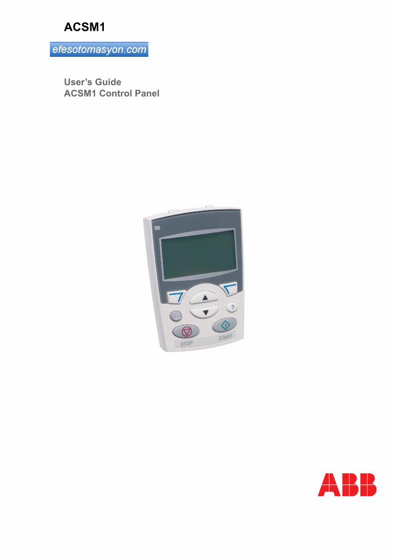
ACSM1
User’s GuideACSM1 Control Panel
ACSM1 Drive Manuals
*A multilingual quick installation guide is included with the delivery.
DRIVE HARDWARE MANUAL*
ACSM1-04 Drive Modules (0.75 to 45 kW) Hardware Manual – 3AFE68797543 (English)ACSM1-04 Drive Modules (55 to 110 kW) Hardware Manual – 3AFE68912130 (English)ACSM1-04Lx Liquid-cooled Drive Modules (55 to 160 kW) Hardware Manual – 3AUA0000022083 (English)
DRIVE FIRMWARE MANUALS
ACSM1 Speed and Torque Control Program Firmware Manual – 3AFE68848261 (English)For drives of type ACSM1-04xS…ACSM1 Motion Control Program Firmware Manual – 3AFE68848270 (English)For drives of type ACSM1-04xM…
DRIVE PC TOOLS MANUALS
DriveStudio User Manual – 3AFE68749026 (English)DriveSPC User Manual – 3AFE68836590 (English)
APPLICATION GUIDES
Functional Safety Solutions with ACSM1 Drives Application Guide – 3AUA0000031517 (English)Safe Torque Off Function (STO) Application Guide – 3AFE68929814 (English)System Engineering Manual – 3AFE68978297 (English)ACSM1 Fieldbus Control with FPBA-01 PROFIBUS DP Adapter Module and ABB AC500 PLC; Application Guide – 3AUA0000049359 (English)
OPTION MANUALS
FIO-01 Digital I/O Extension User’s Manual* – 3AFE68784921 (English)FIO-11 Analog I/O Extension User’s Manual* – 3AFE68784930 (English)FEN-01 TTL Encoder Interface User’s Manual* – 3AFE68784603 (English)FEN-11 Absolute Encoder Interface User’s Manual* – 3AFE68784841 (English)FEN-21 Resolver Interface User’s Manual* – 3AFE68784859 (English)FEN-31 HTL Encoder Interface User’s Manual* – 3AUA0000031044 (English)ACSM1 Control Panel User’s Guide – 3AUA0000020131 (English)

ACSM1 Control Panel
User’s Guide
3AUA0000020131 Rev BEN
EFFECTIVE: 2009-08-12
© 2009 ABB Oy. All Rights Reserved.


5
Table of contents
Table of contents
About the manual
What this chapter contains . . . . . . . . . . . . . . . . . . . . . . . . . . . . . . . . . . . . . . . . . . . . . . . . . . . . . . . . 7Compatibility . . . . . . . . . . . . . . . . . . . . . . . . . . . . . . . . . . . . . . . . . . . . . . . . . . . . . . . . . . . . . . . . . . . 7Safety . . . . . . . . . . . . . . . . . . . . . . . . . . . . . . . . . . . . . . . . . . . . . . . . . . . . . . . . . . . . . . . . . . . . . . . . 7Intended audience . . . . . . . . . . . . . . . . . . . . . . . . . . . . . . . . . . . . . . . . . . . . . . . . . . . . . . . . . . . . . . . 7Product and service inquiries . . . . . . . . . . . . . . . . . . . . . . . . . . . . . . . . . . . . . . . . . . . . . . . . . . . . . . 7Product training . . . . . . . . . . . . . . . . . . . . . . . . . . . . . . . . . . . . . . . . . . . . . . . . . . . . . . . . . . . . . . . . . 7Providing feedback on ABB Drives manuals . . . . . . . . . . . . . . . . . . . . . . . . . . . . . . . . . . . . . . . . . . . 7
Hardware description
What this chapter contains . . . . . . . . . . . . . . . . . . . . . . . . . . . . . . . . . . . . . . . . . . . . . . . . . . . . . . . . 9About control panels . . . . . . . . . . . . . . . . . . . . . . . . . . . . . . . . . . . . . . . . . . . . . . . . . . . . . . . . . . . . . 9Compatibility . . . . . . . . . . . . . . . . . . . . . . . . . . . . . . . . . . . . . . . . . . . . . . . . . . . . . . . . . . . . . . . . . . . 9ACSM1 Control Panel . . . . . . . . . . . . . . . . . . . . . . . . . . . . . . . . . . . . . . . . . . . . . . . . . . . . . . . . . . . 10
Features . . . . . . . . . . . . . . . . . . . . . . . . . . . . . . . . . . . . . . . . . . . . . . . . . . . . . . . . . . . . . . . . . . . 10Overview . . . . . . . . . . . . . . . . . . . . . . . . . . . . . . . . . . . . . . . . . . . . . . . . . . . . . . . . . . . . . . . . . . . 10Maintenance . . . . . . . . . . . . . . . . . . . . . . . . . . . . . . . . . . . . . . . . . . . . . . . . . . . . . . . . . . . . . . . . 10Status line . . . . . . . . . . . . . . . . . . . . . . . . . . . . . . . . . . . . . . . . . . . . . . . . . . . . . . . . . . . . . . . . . . 11
Installation
What this chapter contains . . . . . . . . . . . . . . . . . . . . . . . . . . . . . . . . . . . . . . . . . . . . . . . . . . . . . . . 13Connecting the panel to the drive . . . . . . . . . . . . . . . . . . . . . . . . . . . . . . . . . . . . . . . . . . . . . . . . . . 13The cable . . . . . . . . . . . . . . . . . . . . . . . . . . . . . . . . . . . . . . . . . . . . . . . . . . . . . . . . . . . . . . . . . . . . . 13Mounting the control panel . . . . . . . . . . . . . . . . . . . . . . . . . . . . . . . . . . . . . . . . . . . . . . . . . . . . . . . 14
Mounting template . . . . . . . . . . . . . . . . . . . . . . . . . . . . . . . . . . . . . . . . . . . . . . . . . . . . . . . . . . . 15Gasket . . . . . . . . . . . . . . . . . . . . . . . . . . . . . . . . . . . . . . . . . . . . . . . . . . . . . . . . . . . . . . . . . . . . 16
Operation
What this chapter contains . . . . . . . . . . . . . . . . . . . . . . . . . . . . . . . . . . . . . . . . . . . . . . . . . . . . . . . 17Basics of operation . . . . . . . . . . . . . . . . . . . . . . . . . . . . . . . . . . . . . . . . . . . . . . . . . . . . . . . . . . . . . 17List of tasks . . . . . . . . . . . . . . . . . . . . . . . . . . . . . . . . . . . . . . . . . . . . . . . . . . . . . . . . . . . . . . . . . . . 18Help and panel version – Any mode . . . . . . . . . . . . . . . . . . . . . . . . . . . . . . . . . . . . . . . . . . . . . . . . 19
How to get help . . . . . . . . . . . . . . . . . . . . . . . . . . . . . . . . . . . . . . . . . . . . . . . . . . . . . . . . . . . . . . 19How to find out the panel version . . . . . . . . . . . . . . . . . . . . . . . . . . . . . . . . . . . . . . . . . . . . . . . . 19
Basic operations – Any mode . . . . . . . . . . . . . . . . . . . . . . . . . . . . . . . . . . . . . . . . . . . . . . . . . . . . . 20How to start, stop and switch between local and remote control . . . . . . . . . . . . . . . . . . . . . . . . 20
Output mode . . . . . . . . . . . . . . . . . . . . . . . . . . . . . . . . . . . . . . . . . . . . . . . . . . . . . . . . . . . . . . . . . . 21How to change the direction of the motor rotation . . . . . . . . . . . . . . . . . . . . . . . . . . . . . . . . . . . 21
Table of contents
6
How to select the monitored signals . . . . . . . . . . . . . . . . . . . . . . . . . . . . . . . . . . . . . . . . . . . . . 22How to set the speed, frequency, torque or position reference in the Output mode . . . . . . . . . 23How to adjust the display contrast . . . . . . . . . . . . . . . . . . . . . . . . . . . . . . . . . . . . . . . . . . . . . . . 23
Parameters . . . . . . . . . . . . . . . . . . . . . . . . . . . . . . . . . . . . . . . . . . . . . . . . . . . . . . . . . . . . . . . . . . . 24How to select a parameter and change its value . . . . . . . . . . . . . . . . . . . . . . . . . . . . . . . . . . . . 24How to change the value of value pointer parameters . . . . . . . . . . . . . . . . . . . . . . . . . . . . . . . 25How to change the value of bit pointer parameter to point to the value of a bitin another signal . . . . . . . . . . . . . . . . . . . . . . . . . . . . . . . . . . . . . . . . . . . . . . . . . . . . . . . . . . . . 27How to change the value of bit pointer parameter to fixed 0 (FALSE) or 1 (TRUE) . . . . . . . . . 29
Fault Logger . . . . . . . . . . . . . . . . . . . . . . . . . . . . . . . . . . . . . . . . . . . . . . . . . . . . . . . . . . . . . . . . . . 31How to view faults . . . . . . . . . . . . . . . . . . . . . . . . . . . . . . . . . . . . . . . . . . . . . . . . . . . . . . . . . . . 31How to reset faults . . . . . . . . . . . . . . . . . . . . . . . . . . . . . . . . . . . . . . . . . . . . . . . . . . . . . . . . . . . 31
Time & Date . . . . . . . . . . . . . . . . . . . . . . . . . . . . . . . . . . . . . . . . . . . . . . . . . . . . . . . . . . . . . . . . . . 32How to show or hide the clock, change display formats, set the date and timeand enable or disable clock transitions according to the daylight saving changes . . . . . . . . . . 32
Parameter Backup . . . . . . . . . . . . . . . . . . . . . . . . . . . . . . . . . . . . . . . . . . . . . . . . . . . . . . . . . . . . . 34How to backup and restore parameters . . . . . . . . . . . . . . . . . . . . . . . . . . . . . . . . . . . . . . . . . . . 35How to view information about the backup . . . . . . . . . . . . . . . . . . . . . . . . . . . . . . . . . . . . . . . . 41
Reference Edit . . . . . . . . . . . . . . . . . . . . . . . . . . . . . . . . . . . . . . . . . . . . . . . . . . . . . . . . . . . . . . . . 42How to edit reference value . . . . . . . . . . . . . . . . . . . . . . . . . . . . . . . . . . . . . . . . . . . . . . . . . . . . 42
Drive Info . . . . . . . . . . . . . . . . . . . . . . . . . . . . . . . . . . . . . . . . . . . . . . . . . . . . . . . . . . . . . . . . . . . . 43How to view drive info . . . . . . . . . . . . . . . . . . . . . . . . . . . . . . . . . . . . . . . . . . . . . . . . . . . . . . . . 43
Table of contents
7
About the manual
What this chapter containsThe chapter describes the compatibility and intended audience of this manual. There is also information about finding the safety instructions.
CompatibilityThe manual is compatible with the control panel of the ACSM1 drive.
SafetyFollow all safety instructions delivered with the drive.
• Read the complete safety instructions before you install, commission, or use the drive. The complete safety instructions are given at the beginning of the Hardware Manual.
• Read the software function specific warnings and notes before changing the default settings of the function. For warnings and notes, see appropriate Firmware Manual.
Intended audienceThis manual is intended for persons who install and use the panel.
Product and service inquiriesAddress any inquiries about the product to your local ABB representative, quoting the type code and serial number of the unit in question. A listing of ABB sales, support and service contacts can be found by navigating to www.abb.com/drives and selecting Sales, Support and Service network.
Product trainingFor information on ABB product training, navigate to www.abb.com/drives and select Training courses.
Providing feedback on ABB Drives manualsYour comments on our manuals are welcome. Go to www.abb.com/drives and select Document Library – Manuals feedback form (LV AC drives).
About the manual

8
About the manual
9
Hardware description
What this chapter containsThe chapter describes the control panel keys. It also instructs in using the panel in control, monitoring and changing the settings.
About control panelsUse a control panel to control the ACSM1, read status data, and adjust parameters.
CompatibilityThe manual is compatible with the ACSM1 drive control panel SW rev 3.05 and Flash rev 3.4.1.6 or later.
See page 19 for how to find out the control panel version.
Hardware description
10
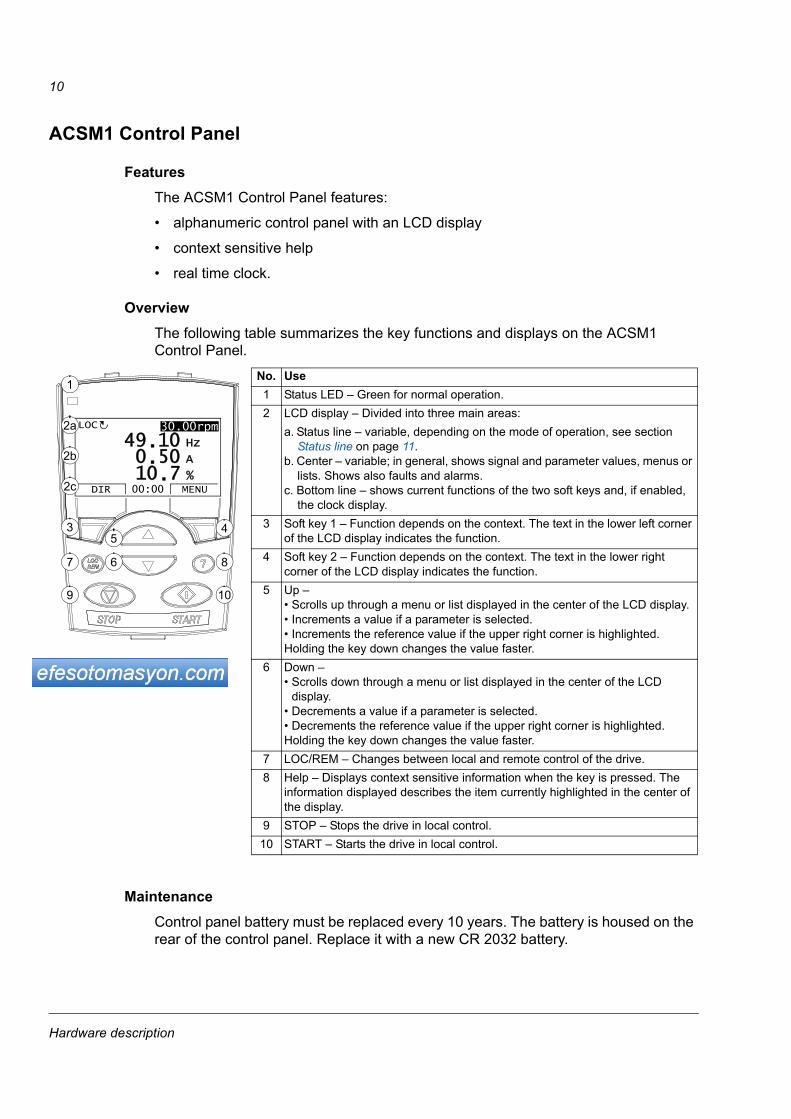
ACSM1 Control Panel
FeaturesThe ACSM1 Control Panel features:
• alphanumeric control panel with an LCD display
• context sensitive help
• real time clock.
OverviewThe following table summarizes the key functions and displays on the ACSM1 Control Panel.
MaintenanceControl panel battery must be replaced every 10 years. The battery is housed on the rear of the control panel. Replace it with a new CR 2032 battery.
30.10HzLOC
DIR 12:45 MENU
400RPM
1200 RPM12.4 A
405 dm3/s
3 45
67 8
9 10
No. Use1 Status LED – Green for normal operation.2 LCD display – Divided into three main areas:
a. Status line – variable, depending on the mode of operation, see section Status line on page 11.
b. Center – variable; in general, shows signal and parameter values, menus or lists. Shows also faults and alarms.
c. Bottom line – shows current functions of the two soft keys and, if enabled, the clock display.
3 Soft key 1 – Function depends on the context. The text in the lower left corner of the LCD display indicates the function.
4 Soft key 2 – Function depends on the context. The text in the lower right corner of the LCD display indicates the function.
5 Up – • Scrolls up through a menu or list displayed in the center of the LCD display. • Increments a value if a parameter is selected.• Increments the reference value if the upper right corner is highlighted.Holding the key down changes the value faster.
6 Down – • Scrolls down through a menu or list displayed in the center of the LCD
display. • Decrements a value if a parameter is selected.• Decrements the reference value if the upper right corner is highlighted.Holding the key down changes the value faster.
7 LOC/REM – Changes between local and remote control of the drive.8 Help – Displays context sensitive information when the key is pressed. The
information displayed describes the item currently highlighted in the center of the display.
9 STOP – Stops the drive in local control.10 START – Starts the drive in local control.
30.00rpm
50 A
10 Hz
7 %10.0.
49.LOC
DIR MENU00:00
1
2a
2b
2c
30.00rpm
Hardware description
11
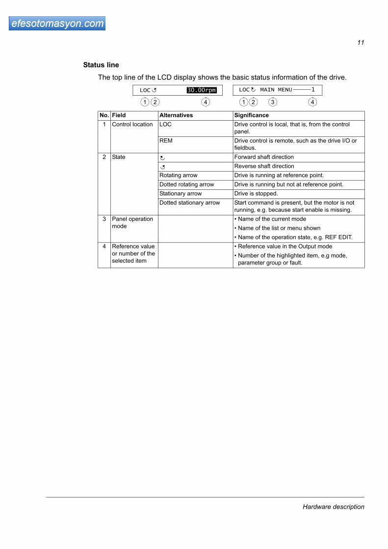
Status lineThe top line of the LCD display shows the basic status information of the drive.
No. Field Alternatives Significance1 Control location LOC Drive control is local, that is, from the control
panel.REM Drive control is remote, such as the drive I/O or
fieldbus.2 State Forward shaft direction
Reverse shaft directionRotating arrow Drive is running at reference point.Dotted rotating arrow Drive is running but not at reference point.Stationary arrow Drive is stopped.Dotted stationary arrow Start command is present, but the motor is not
running, e.g. because start enable is missing.3 Panel operation
mode• Name of the current mode• Name of the list or menu shown• Name of the operation state, e.g. REF EDIT.
4 Reference value or number of the selected item
• Reference value in the Output mode• Number of the highlighted item, e.g mode,
parameter group or fault.
30.00rpmLOC
1 2 4
LOC MAIN MENU 1
1 2 3 4
Hardware description

12
Hardware description
13
Installation
What this chapter containsThe chapter describes connecting and mounting of the control panel.
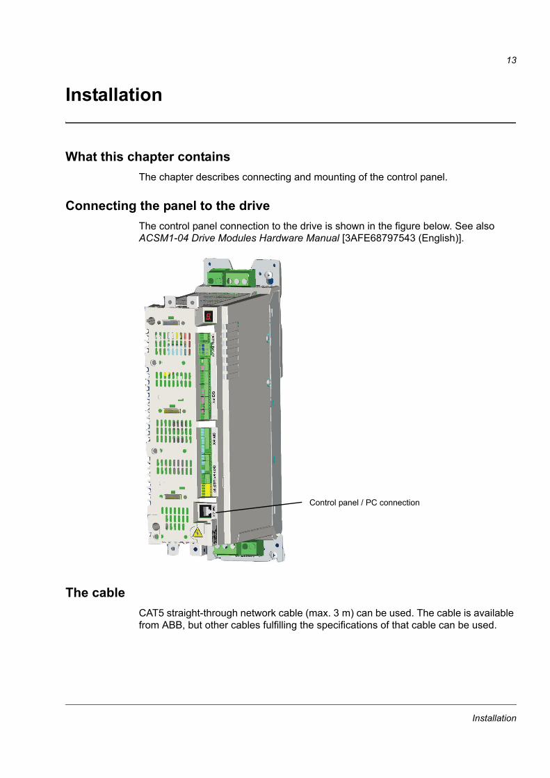
Connecting the panel to the driveThe control panel connection to the drive is shown in the figure below. See also ACSM1-04 Drive Modules Hardware Manual [3AFE68797543 (English)].
The cableCAT5 straight-through network cable (max. 3 m) can be used. The cable is available from ABB, but other cables fulfilling the specifications of that cable can be used.
Control panel / PC connection
Installation

14
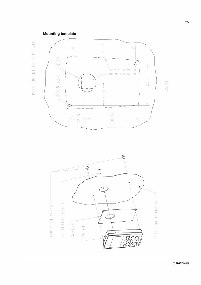
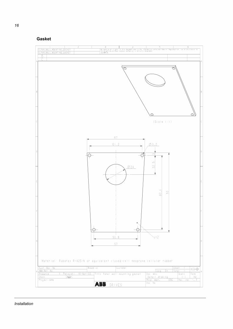
Mounting the control panelThere are two panel mounting kits, IP21 (68294673) and IP66 (68829593). The kits contain an extension cable, a gasket and other mounting accessories needed for installing the panel to the cabinet door. The kits also contain installation instructions as drawings, see the figures below.
Installation
15
Mounting template
Installation
16
Gasket
Installation
17
Operation
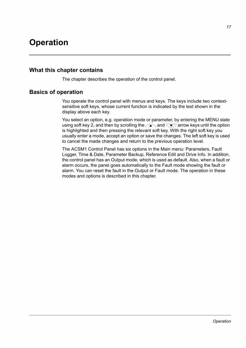
What this chapter containsThe chapter describes the operation of the control panel.
Basics of operationYou operate the control panel with menus and keys. The keys include two context-sensitive soft keys, whose current function is indicated by the text shown in the display above each key.
You select an option, e.g. operation mode or parameter, by entering the MENU state using soft key 2, and then by scrolling the and arrow keys until the option is highlighted and then pressing the relevant soft key. With the right soft key you usually enter a mode, accept an option or save the changes. The left soft key is used to cancel the made changes and return to the previous operation level.
The ACSM1 Control Panel has six options in the Main menu: Parameters, Fault Logger, Time & Date, Parameter Backup, Reference Edit and Drive Info. In addition, the control panel has an Output mode, which is used as default. Also, when a fault or alarm occurs, the panel goes automatically to the Fault mode showing the fault or alarm. You can reset the fault in the Output or Fault mode. The operation in these modes and options is described in this chapter.
Operation
18
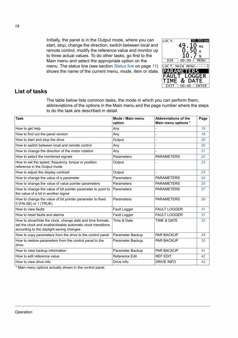
Initially, the panel is in the Output mode, where you can start, stop, change the direction, switch between local and remote control, modify the reference value and monitor up to three actual values. To do other tasks, go first to the Main menu and select the appropriate option on the menu. The status line (see section Status line on page 11) shows the name of the current menu, mode, item or state.
List of tasksThe table below lists common tasks, the mode in which you can perform them, abbreviations of the options in the Main menu and the page number where the steps to do the task are described in detail.
Task Mode / Main menu option
Abbreviations of the Main menu options *
Page
How to get help Any - 19How to find out the panel version Any - 19How to start and stop the drive Output - 20How to switch between local and remote control Any - 20How to change the direction of the motor rotation Any - 21How to select the monitored signals Parameters PARAMETERS 22How to set the speed, frequency, torque or position reference in the Output mode
Output - 23
How to adjust the display contrast Output - 23How to change the value of a parameter Parameters PARAMETERS 24How to change the value of value pointer parameters Parameters PARAMETERS 25How to change the value of bit pointer parameter to point to the value of a bit in another signal
Parameters PARAMETERS 27
How to change the value of bit pointer parameter to fixed 0 (FALSE) or 1 (TRUE)
Parameters PARAMETERS 29
How to view faults Fault Logger FAULT LOGGER 31How to reset faults and alarms Fault Logger FAULT LOGGER 31How to show/hide the clock, change date and time formats, set the clock and enable/disable automatic clock transitions according to the daylight saving changes
Time & Date TIME & DATE 32
How to copy parameters from the drive to the control panel Parameter Backup PAR BACKUP 35How to restore parameters from the control panel to the drive
Parameter Backup PAR BACKUP 35
How to view backup information Parameter Backup PAR BACKUP 41How to edit reference value Reference Edit REF EDIT 42How to view drive info Drive Info DRIVE INFO 43* Main menu options actually shown in the control panel.
PARAMETERS FAULT LOGGERTIME & DATEEXIT ENTER00:00
MAIN MENU 1LOC
50 A
10 Hz
7 %10.0.
49.LOC
DIR MENU00:00
30.00rpm
Operation
19
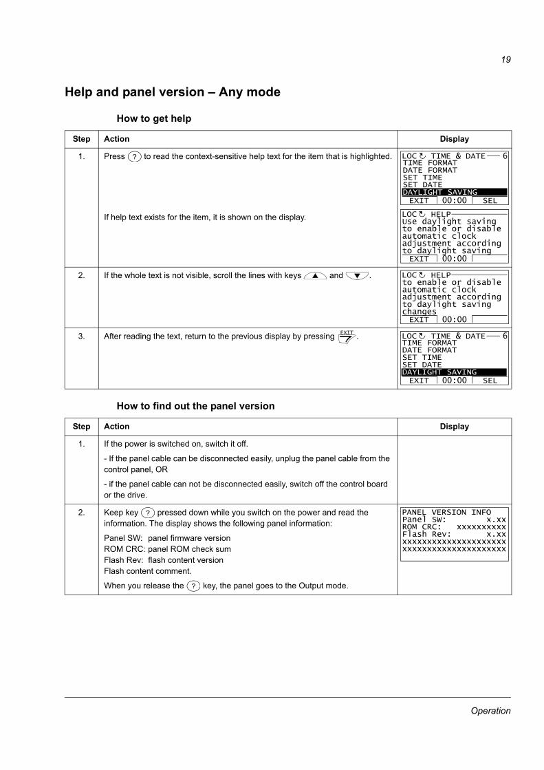
Help and panel version – Any mode
How to get help
How to find out the panel version
Step Action Display
1. Press to read the context-sensitive help text for the item that is highlighted.
If help text exists for the item, it is shown on the display.
2. If the whole text is not visible, scroll the lines with keys and .
3. After reading the text, return to the previous display by pressing .
Step Action Display
1. If the power is switched on, switch it off.
- If the panel cable can be disconnected easily, unplug the panel cable from the control panel, OR
- if the panel cable can not be disconnected easily, switch off the control board or the drive.
2. Keep key pressed down while you switch on the power and read the information. The display shows the following panel information:
Panel SW: panel firmware versionROM CRC: panel ROM check sumFlash Rev: flash content versionFlash content comment.
When you release the key, the panel goes to the Output mode.
? TIME FORMATDATE FORMATSET TIMESET DATEDAYLIGHT SAVING
TIME & DATE 6
EXIT SEL00:00
LOC
EXIT 00:00
Use daylight saving to enable or disable automatic clock adjustment according to daylight saving
HELPLOC
EXIT 00:00
to enable or disable automatic clock adjustment according to daylight saving changes
HELPLOC
EXIT TIME FORMATDATE FORMATSET TIMESET DATEDAYLIGHT SAVING
TIME & DATE 6
EXIT SEL00:00
LOC
?
?
Panel SW: x.xxROM CRC: xxxxxxxxxxFlash Rev: x.xxxxxxxxxxxxxxxxxxxxxxxxxxxxxxxxxxxxxxxxxxxx
PANEL VERSION INFO
Operation
20
Basic operations – Any mode
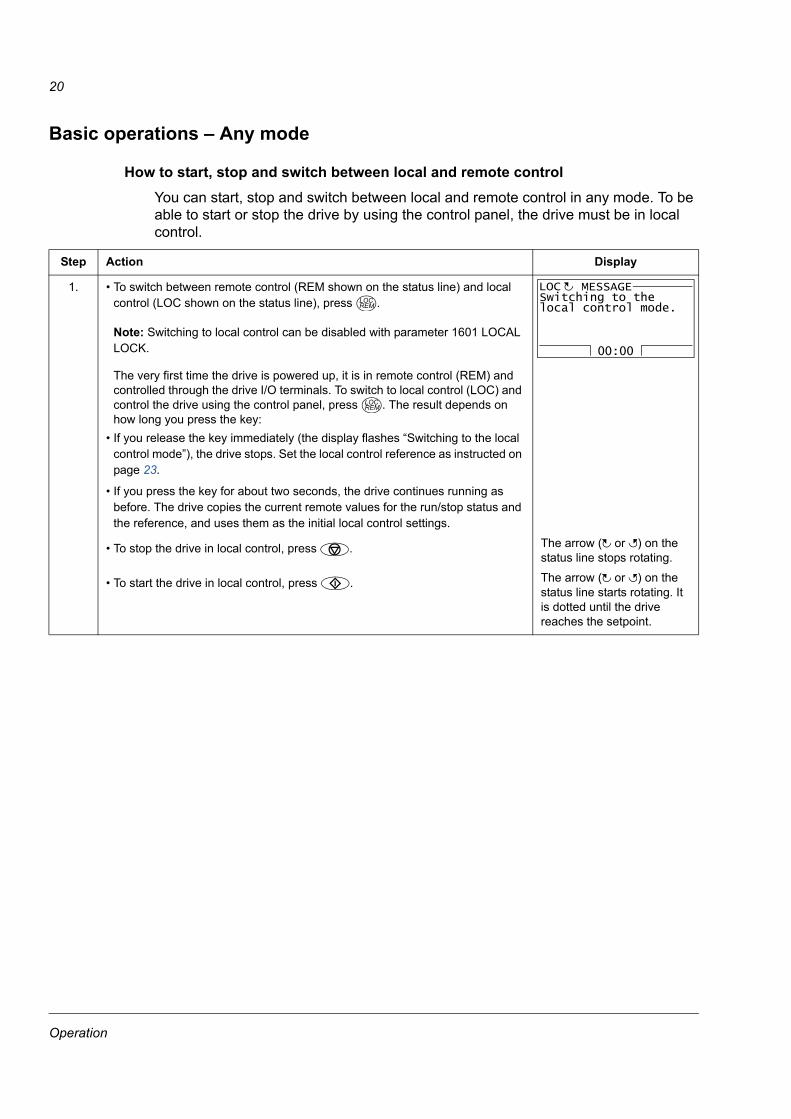
How to start, stop and switch between local and remote controlYou can start, stop and switch between local and remote control in any mode. To be able to start or stop the drive by using the control panel, the drive must be in local control.
Step Action Display
1. • To switch between remote control (REM shown on the status line) and local control (LOC shown on the status line), press .
Note: Switching to local control can be disabled with parameter 1601 LOCAL LOCK.
The very first time the drive is powered up, it is in remote control (REM) and controlled through the drive I/O terminals. To switch to local control (LOC) and control the drive using the control panel, press . The result depends on how long you press the key:
• If you release the key immediately (the display flashes “Switching to the local control mode”), the drive stops. Set the local control reference as instructed on page 23.
• If you press the key for about two seconds, the drive continues running as before. The drive copies the current remote values for the run/stop status and the reference, and uses them as the initial local control settings.
• To stop the drive in local control, press . The arrow ( or ) on the status line stops rotating.
• To start the drive in local control, press . The arrow ( or ) on the status line starts rotating. It is dotted until the drive reaches the setpoint.
LOCREM
00:00
Switching to thelocal control mode.
MESSAGELOC
LOCREM
Operation
21
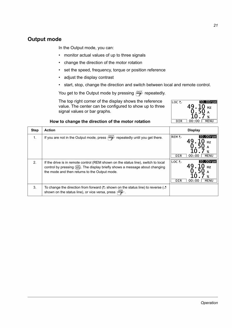
Output modeIn the Output mode, you can:
• monitor actual values of up to three signals
• change the direction of the motor rotation
• set the speed, frequency, torque or position reference
• adjust the display contrast
• start, stop, change the direction and switch between local and remote control.
You get to the Output mode by pressing repeatedly.
The top right corner of the display shows the reference value. The center can be configured to show up to three signal values or bar graphs.
How to change the direction of the motor rotation
Step Action Display
1. If you are not in the Output mode, press repeatedly until you get there.
2. If the drive is in remote control (REM shown on the status line), switch to local control by pressing . The display briefly shows a message about changing the mode and then returns to the Output mode.
3. To change the direction from forward ( shown on the status line) to reverse ( shown on the status line), or vice versa, press .
EXIT
50 A
10 Hz
7 %10.0.
49.LOC
DIR MENU00:00
30.00rpm
EXIT
50 A
10 Hz
7 %10.0.
49.REM
DIR MENU00:00
30.00rpm
LOCREM
50 A
10 Hz
7 %10.0.
49.LOC
DIR MENU00:00
30.00rpm
DIR
Operation
22
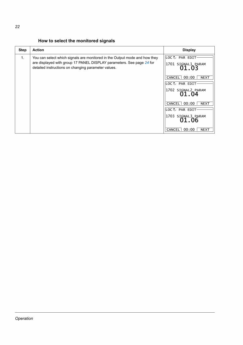
How to select the monitored signals
Step Action Display
1. You can select which signals are monitored in the Output mode and how they are displayed with group 17 PANEL DISPLAY parameters. See page 24 for detailed instructions on changing parameter values.
1701 SIGNAL1 PARAM
PAR EDIT
01.03
CANCEL NEXT00:00
LOC
1702 SIGNAL2 PARAM
PAR EDIT
01.04
CANCEL NEXT00:00
LOC
1703 SIGNAL3 PARAM
PAR EDIT
01.06
CANCEL NEXT00:00
LOC
Operation
23
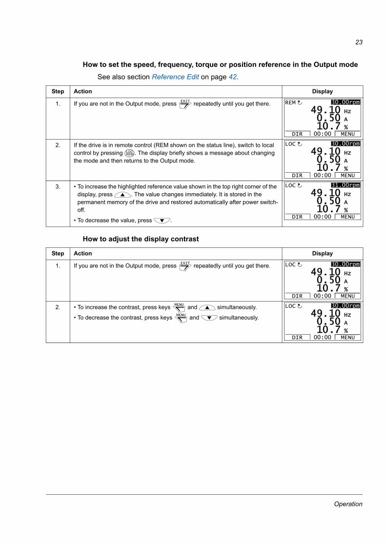
How to set the speed, frequency, torque or position reference in the Output modeSee also section Reference Edit on page 42.
How to adjust the display contrast
Step Action Display
1. If you are not in the Output mode, press repeatedly until you get there.
2. If the drive is in remote control (REM shown on the status line), switch to local control by pressing . The display briefly shows a message about changing the mode and then returns to the Output mode.
3. • To increase the highlighted reference value shown in the top right corner of the display, press . The value changes immediately. It is stored in the permanent memory of the drive and restored automatically after power switch-off.
• To decrease the value, press .
Step Action Display
1. If you are not in the Output mode, press repeatedly until you get there.
2. • To increase the contrast, press keys and simultaneously.
• To decrease the contrast, press keys and simultaneously.
EXIT
50 A
10 Hz
7 %10.0.
49.REM
DIR MENU00:00
30.00rpm
LOCREM
50 A
10 Hz
7 %10.0.
49.LOC
DIR MENU00:00
30.00rpm
50 A
10 Hz
7 %10.0.
49.LOC
DIR MENU00:00
31.00rpm
EXIT
50 A
10 Hz
7 %10.0.
49.LOC
DIR MENU00:00
30.00rpm
MENU
MENU
50 A
10 Hz
7 %10.0.
49.LOC
DIR MENU00:00
30.00rpm
Operation
24
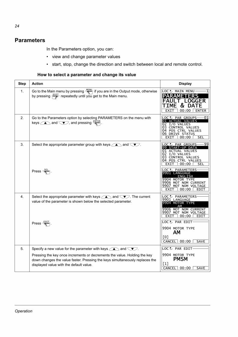
ParametersIn the Parameters option, you can:
• view and change parameter values
• start, stop, change the direction and switch between local and remote control.
How to select a parameter and change its value
Step Action Display
1. Go to the Main menu by pressing if you are in the Output mode, otherwise by pressing repeatedly until you get to the Main menu.
2. Go to the Parameters option by selecting PARAMETERS on the menu with keys and , and pressing .
3. Select the appropriate parameter group with keys and .
Press .
4. Select the appropriate parameter with keys and . The current value of the parameter is shown below the selected parameter.
Press .
5. Specify a new value for the parameter with keys and .
Pressing the key once increments or decrements the value. Holding the key down changes the value faster. Pressing the keys simultaneously replaces the displayed value with the default value.
MENU
EXIT
PARAMETERS FAULT LOGGERTIME & DATEEXIT ENTER00:00
MAIN MENU 1LOC
ENTER 01 ACTUAL VALUES02 I/O VALUES03 CONTROL VALUES04 POS CTRL VALUES06 DRIVE STATUSEXIT SEL00:00
PAR GROUPS 01LOC
99 START-UP DATA01 ACTUAL VALUES02 I/O VALUES03 CONTROL VALUES04 POS CTRL VALUESEXIT SEL00:00
PAR GROUPS 99LOC
SEL 9901 LANGUAGE
ENGLISH9904 MOTOR TYPE9906 MOT NOM CURRENT9907 MOT NOM VOLTAGE
PARAMETERS
EXIT EDIT00:00
LOC
9901 LANGUAGE9904 MOTOR TYPE AM9906 MOT NOM CURRENT9907 MOT NOM VOLTAGE
PARAMETERS
EXIT EDIT00:00
LOC
EDIT 9904 MOTOR TYPE
PAR EDIT
AM
CANCEL SAVE00:00[0]
LOC
9904 MOTOR TYPE
PAR EDIT
PMSM
CANCEL SAVE00:00[1]
LOC
Operation
25
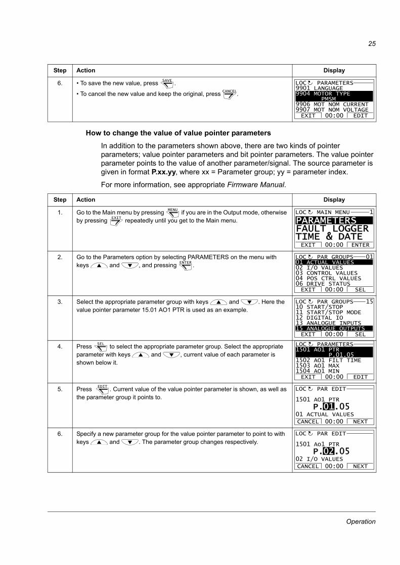
How to change the value of value pointer parametersIn addition to the parameters shown above, there are two kinds of pointer parameters; value pointer parameters and bit pointer parameters. The value pointer parameter points to the value of another parameter/signal. The source parameter is given in format P.xx.yy, where xx = Parameter group; yy = parameter index.
For more information, see appropriate Firmware Manual.
6. • To save the new value, press .
• To cancel the new value and keep the original, press .
Step Action Display
1. Go to the Main menu by pressing if you are in the Output mode, otherwise by pressing repeatedly until you get to the Main menu.
2. Go to the Parameters option by selecting PARAMETERS on the menu with keys and , and pressing .
3. Select the appropriate parameter group with keys and . Here the value pointer parameter 15.01 AO1 PTR is used as an example.
4. Press to select the appropriate parameter group. Select the appropriate parameter with keys and , current value of each parameter is shown below it.
5. Press . Current value of the value pointer parameter is shown, as well as the parameter group it points to.
6. Specify a new parameter group for the value pointer parameter to point to with keys and . The parameter group changes respectively.
Step Action DisplaySAVE
CANCEL
9901 LANGUAGE9904 MOTOR TYPE PMSM9906 MOT NOM CURRENT9907 MOT NOM VOLTAGE
PARAMETERS
EXIT EDIT00:00
LOC
MENU
EXIT
PARAMETERS FAULT LOGGERTIME & DATEEXIT ENTER00:00
MAIN MENU 1LOC
ENTER 01 ACTUAL VALUES02 I/O VALUES03 CONTROL VALUES04 POS CTRL VALUES06 DRIVE STATUSEXIT SEL00:00
PAR GROUPS 01LOC
10 START/STOP11 START/STOP MODE12 DIGITAL IO13 ANALOGUE INPUTS15 ANALOGUE OUTPUTSEXIT SEL00:00
PAR GROUPS 15LOC
SEL 1501 AO1 PTR P.01.051502 AO1 FILT TIME1503 AO1 MAX1504 AO1 MIN
PARAMETERS
EXIT EDIT00:00
LOC
EDIT 1501 AO1 PTR
PAR EDIT
P.01.05
CANCEL NEXT00:0001 ACTUAL VALUES
LOC
1501 Ao1 PTR
PAR EDIT
P.02.05
CANCEL NEXT00:0002 I/O VALUES
LOC
Operation
26
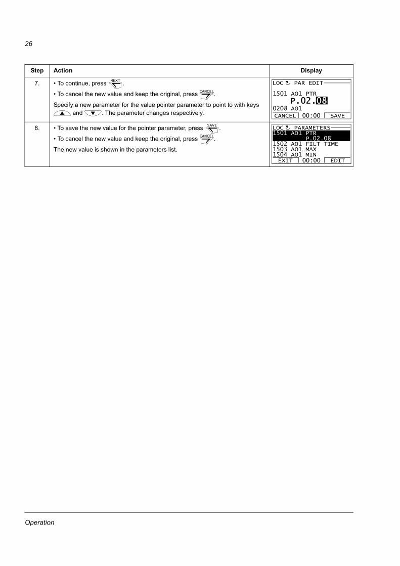
7. • To continue, press .
• To cancel the new value and keep the original, press .
Specify a new parameter for the value pointer parameter to point to with keys and . The parameter changes respectively.
8. • To save the new value for the pointer parameter, press .
• To cancel the new value and keep the original, press .
The new value is shown in the parameters list.
Step Action DisplayNEXT
CANCEL
1501 AO1 PTR
PAR EDIT
P.02.08
CANCEL SAVE00:000208 AO1
LOC
SAVE
CANCEL
1501 AO1 PTR P.02.081502 AO1 FILT TIME1503 AO1 MAX1504 AO1 MIN
PARAMETERSLOC
EXIT EDIT00:00
Operation
27
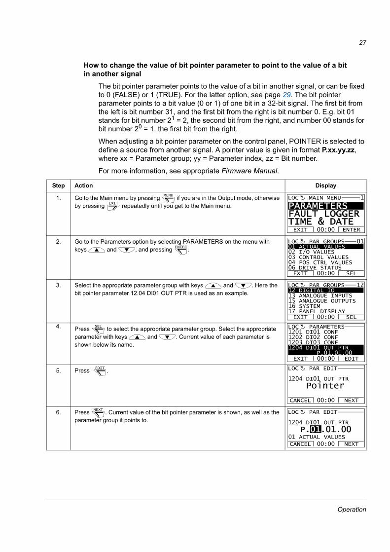
How to change the value of bit pointer parameter to point to the value of a bitin another signal
The bit pointer parameter points to the value of a bit in another signal, or can be fixed to 0 (FALSE) or 1 (TRUE). For the latter option, see page 29. The bit pointer parameter points to a bit value (0 or 1) of one bit in a 32-bit signal. The first bit from the left is bit number 31, and the first bit from the right is bit number 0. E.g. bit 01 stands for bit number 21 = 2, the second bit from the right, and number 00 stands for bit number 20 = 1, the first bit from the right.
When adjusting a bit pointer parameter on the control panel, POINTER is selected to define a source from another signal. A pointer value is given in format P.xx.yy.zz, where xx = Parameter group; yy = Parameter index, zz = Bit number.
For more information, see appropriate Firmware Manual.
Step Action Display
1. Go to the Main menu by pressing if you are in the Output mode, otherwise by pressing repeatedly until you get to the Main menu.
2. Go to the Parameters option by selecting PARAMETERS on the menu with keys and , and pressing .
3. Select the appropriate parameter group with keys and . Here the bit pointer parameter 12.04 DI01 OUT PTR is used as an example.
4. Press to select the appropriate parameter group. Select the appropriate parameter with keys and . Current value of each parameter is shown below its name.
5. Press .
6. Press . Current value of the bit pointer parameter is shown, as well as the parameter group it points to.
MENU
EXIT
PARAMETERS FAULT LOGGERTIME & DATEEXIT ENTER00:00
MAIN MENU 1LOC
ENTER 01 ACTUAL VALUES02 I/O VALUES03 CONTROL VALUES04 POS CTRL VALUES06 DRIVE STATUSEXIT SEL00:00
PAR GROUPS 01LOC
12 DIGITAL IO13 ANALOGUE INPUTS15 ANALOGUE OUTPUTS16 SYSTEM17 PANEL DISPLAYEXIT SEL00:00
PAR GROUPS 12LOC
SEL 1201 DI01 CONF9901 1202 DI02 CONF1203 DI03 CONF1204 DI01 OUT PTR P.01.01.00
PARAMETERS
EXIT EDIT00:00
LOC
EDIT 1204 DI01 OUT PTR
PAR EDIT
Pointer
CANCEL NEXT00:00
LOC
NEXT 1204 DI01 OUT PTR
PAR EDIT
P.01.01.00
CANCEL NEXT00:0001 ACTUAL VALUES
LOC
Operation
28
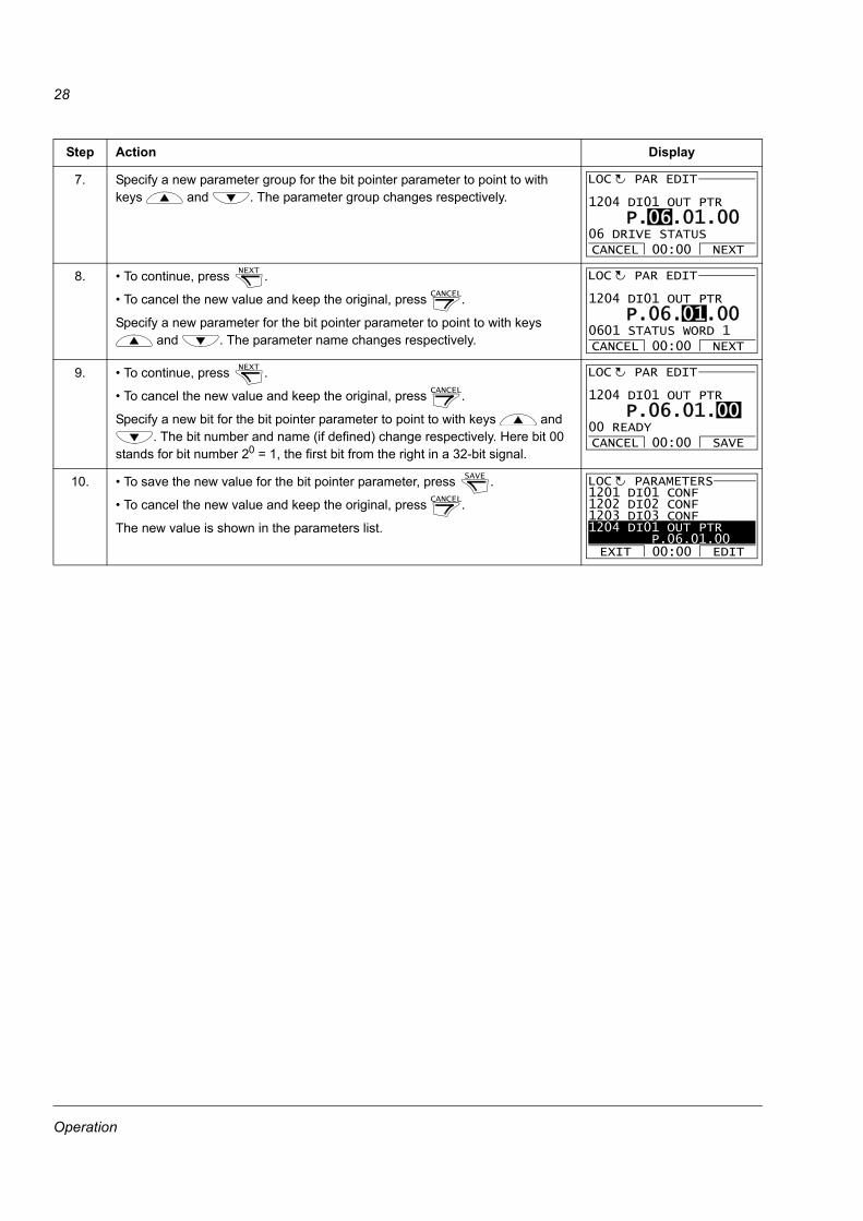
7. Specify a new parameter group for the bit pointer parameter to point to with keys and . The parameter group changes respectively.
8. • To continue, press .
• To cancel the new value and keep the original, press .
Specify a new parameter for the bit pointer parameter to point to with keys and . The parameter name changes respectively.
9. • To continue, press .
• To cancel the new value and keep the original, press .
Specify a new bit for the bit pointer parameter to point to with keys and . The bit number and name (if defined) change respectively. Here bit 00
stands for bit number 20 = 1, the first bit from the right in a 32-bit signal.
10. • To save the new value for the bit pointer parameter, press .
• To cancel the new value and keep the original, press .
The new value is shown in the parameters list.
Step Action Display
1204 DI01 OUT PTR
PAR EDIT
P.06.01.00
CANCEL NEXT00:0006 DRIVE STATUS
LOC
NEXT
CANCEL
1204 DI01 OUT PTR
PAR EDIT
P.06.01.00
CANCEL NEXT00:000601 STATUS WORD 1
LOC
NEXT
CANCEL
1204 DI01 OUT PTR
PAR EDIT
P.06.01.00
CANCEL SAVE00:0000 READY
LOC
SAVE
CANCEL
1201 DI01 CONF9901 1202 DI02 CONF1203 DI03 CONF1204 DI01 OUT PTR P.06.01.00
PARAMETERS
EXIT EDIT00:00
LOC
Operation
29
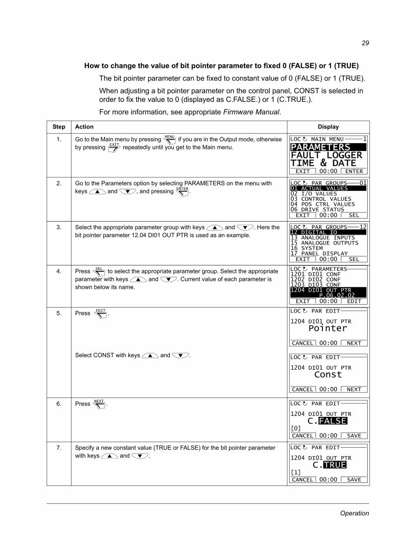
How to change the value of bit pointer parameter to fixed 0 (FALSE) or 1 (TRUE)The bit pointer parameter can be fixed to constant value of 0 (FALSE) or 1 (TRUE).
When adjusting a bit pointer parameter on the control panel, CONST is selected in order to fix the value to 0 (displayed as C.FALSE.) or 1 (C.TRUE.).
For more information, see appropriate Firmware Manual.
Step Action Display
1. Go to the Main menu by pressing if you are in the Output mode, otherwise by pressing repeatedly until you get to the Main menu.
2. Go to the Parameters option by selecting PARAMETERS on the menu with keys and , and pressing .
3. Select the appropriate parameter group with keys and . Here the bit pointer parameter 12.04 DI01 OUT PTR is used as an example.
4. Press to select the appropriate parameter group. Select the appropriate parameter with keys and . Current value of each parameter is shown below its name.
5. Press .
Select CONST with keys and .
6. Press .
7. Specify a new constant value (TRUE or FALSE) for the bit pointer parameterwith keys and .
MENU
EXIT
PARAMETERS FAULT LOGGERTIME & DATEEXIT ENTER00:00
MAIN MENU 1LOC
ENTER 01 ACTUAL VALUES02 I/O VALUES03 CONTROL VALUES04 POS CTRL VALUES06 DRIVE STATUSEXIT SEL00:00
PAR GROUPS 01LOC
12 DIGITAL IO13 ANALOGUE INPUTS15 ANALOGUE OUTPUTS16 SYSTEM17 PANEL DISPLAYEXIT SEL00:00
PAR GROUPS 12LOC
SEL 1201 DI01 CONF9901 1202 DI02 CONF1203 DI03 CONF1204 DI01 OUT PTR P.06.02.02
PARAMETERS
EXIT EDIT00:00
LOC
EDIT 1204 DI01 OUT PTR
PAR EDIT
Pointer
CANCEL NEXT00:00
LOC
1204 DI01 OUT PTR
PAR EDIT
Const
CANCEL NEXT00:00
LOC
NEXT 1204 DI01 OUT PTR
PAR EDIT
C.FALSE
CANCEL SAVE00:00[0]
LOC
1204 DI01 OUT PTR
PAR EDIT
C.TRUE
CANCEL SAVE00:00[1]
LOC
Operation
30
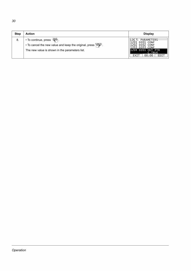
8. • To continue, press .
• To cancel the new value and keep the original, press .
The new value is shown in the parameters list.
Step Action DisplaySAVE
CANCEL
1201 DI01 CONF9901 1202 DI02 CONF1203 DI03 CONF1204 DI01 OUT PTR C.TRUE
PARAMETERS
EXIT EDIT00:00
LOC
Operation

31
Fault LoggerIn the Fault Logger option, you can:
• view the drive fault history
• see the details of the most recent faults
• start, stop, change the direction and switch between local and remote control.
How to view faults
How to reset faults
Step Action Display
1. Go to the Main menu by pressing if you are in the Output mode, otherwise by pressing repeatedly until you get to the Main menu.
2. Go to the Fault Logger option by selecting FAULT LOGGER on the menu with keys and , and pressing .
• If there are no faults in the fault history, corresponding text will be shown.
• If there is a fault history, the display shows the fault log starting with the most recent fault. The number on the row is the fault code according to which the causes and corrective actions are listed in appropriate Firmware Manual.
• To see the details of a fault, select it with keys and , and press .
• Scroll the text with keys and .
• After reading it, press to return to the previous display.
Step Action Display
1. When a fault occurs, text identifying the fault is shown.
• To reset the fault, press .
• To return to the previous display, press .
MENU
EXIT
PARAMETERSFAULT LOGGERTIME & DATEEXIT ENTER00:00
MAIN MENU 2LOC
ENTER
No fault historyfound
MESSAGELOC
36: LOCAL CTRL LOSS 29.04.08 10:45:58
FAULT LOGGER
EXIT DETAIL00:00
LOC 1
DETAIL
EXIT
TIME 10:45:58FAULT CODE 36FAULT CODE EXTENSION
LOCAL CTRL LOSS
EXIT 00:00
LOC
RESET
EXIT
FAULT 36LOCAL CTRL LOSS
FAULT
RESET EXIT
LOC
Operation
32
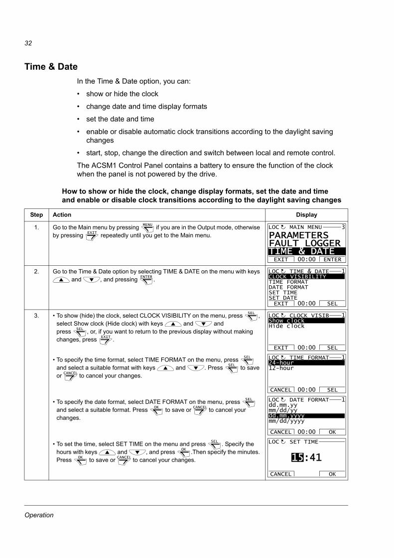
Time & DateIn the Time & Date option, you can:
• show or hide the clock
• change date and time display formats
• set the date and time
• enable or disable automatic clock transitions according to the daylight saving changes
• start, stop, change the direction and switch between local and remote control.
The ACSM1 Control Panel contains a battery to ensure the function of the clock when the panel is not powered by the drive.
How to show or hide the clock, change display formats, set the date and timeand enable or disable clock transitions according to the daylight saving changes
Step Action Display
1. Go to the Main menu by pressing if you are in the Output mode, otherwise by pressing repeatedly until you get to the Main menu.
2. Go to the Time & Date option by selecting TIME & DATE on the menu with keys and , and pressing .
3. • To show (hide) the clock, select CLOCK VISIBILITY on the menu, press , select Show clock (Hide clock) with keys and and press , or, if you want to return to the previous display without making changes, press .
• To specify the time format, select TIME FORMAT on the menu, press and select a suitable format with keys and . Press to save or to cancel your changes.
• To specify the date format, select DATE FORMAT on the menu, press and select a suitable format. Press to save or to cancel your changes.
• To set the time, select SET TIME on the menu and press . Specify the hours with keys and , and press .Then specify the minutes. Press to save or to cancel your changes.
MENU
EXIT
PARAMETERS FAULT LOGGERTIME & DATEEXIT ENTER00:00
MAIN MENU 3LOC
ENTER CLOCK VISIBILITYTIME FORMATDATE FORMATSET TIMESET DATEEXIT SEL00:00
TIME & DATE 1LOC
SEL
SEL
EXIT
Show clockHide clock
EXIT SEL00:00
CLOCK VISIB 1LOC
SEL
SEL
CANCEL
24-hour12-hour
CANCEL SEL00:00
TIME FORMAT 1LOC
SEL
OK CANCEL
dd.mm.yymm/dd/yydd.mm.yyyymm/dd/yyyy
CANCEL OK00:00
DATE FORMAT 1LOC
SEL
OK
OK CANCEL 15:41
SET TIME
CANCEL OK
LOC
Operation

33
• To set the date, select SET DATE on the menu and press . Specify the first part of the date (day or month depending on the selected date format) with keys and , and press . Repeat for the second part. After specifying the year, press . To cancel your changes, press .
• To enable or disable the automatic clock transitions according to the daylight saving changes, select DAYLIGHT SAVING on the menu and press .
Pressing opens the help that shows the beginning and end dates of the period during which daylight saving time is used in each country or area whose daylight saving changes you can select to be followed. Scroll the text with keys and . To return to the previous display, press .
• To disable automatic clock transitions according to the daylight saving changes, select Off and press .
• To enable automatic clock transitions, select the country or area whose daylight saving changes are followed and press .
• To return to the previous display without making changes, press .
Step Action DisplaySEL
OK
OK CANCEL
19.03.2008
SET DATE
CANCEL OK00:00
LOC
SEL
?
EXIT
SEL
SEL
EXIT
OffEUUSAust 1: NSW,Vict..Aust 2:Tasmania..EXIT SEL00:00
DAYLIGHT SAV 1LOC
EXIT 00:00
EU:On: Mar last SundayOff: Oct last Sunday
US:
HELPLOC
Operation
34
Parameter BackupThe Parameter Backup option is used to export parameters from one drive to another or to make a backup of the drive parameters. Uploading stores all drive parameters, including up to four user sets, to the control panel. Selectable subsets of the backup file can then be restored/downloaded from the control panel to the same drive or another drive of the same type (e.g. ACSM1 Motion -> ACSM1 Motion and ACSM1 Speed -> ACSM1 Speed).
In the Parameter Backup option, you can:
• Copy all parameters from the drive to the control panel with MAKE BACKUP TO PANEL. This includes all defined user sets of parameters and internal (not adjustable by the user) parameters such as those changed by the ID Run.
• View the information about the backup stored in the control panel with SHOW BACKUP INFO. This includes e.g. version information etc. of the current backup file in the panel. It is useful to check this information when you are going to restore the parameters to another drive with RESTORE PARS ALL to ensure that the drives are compatible.
• Restore the full parameter set from the control panel to the drive using the RESTORE PARS ALL command. This writes all parameters, including the internal non-user-adjustable motor parameters, to the drive. It does NOT include the user sets of parameters.
Note: Use this function only to restore the parameters from a backup or to restore parameters to systems that are compatible.
• Restore all parameters, except motor data, to the drive with RESTORE PARS NO-IDRUN.
• Restore only motor data parameters to the drive with RESTORE PARS IDRUN.
• Restore all user sets to the drive with RESTORE ALL USER SETS.
• Restore only user set 1…4 to the drive with RESTORE USER SET 1…RESTORE USER SET 4.
Operation
35
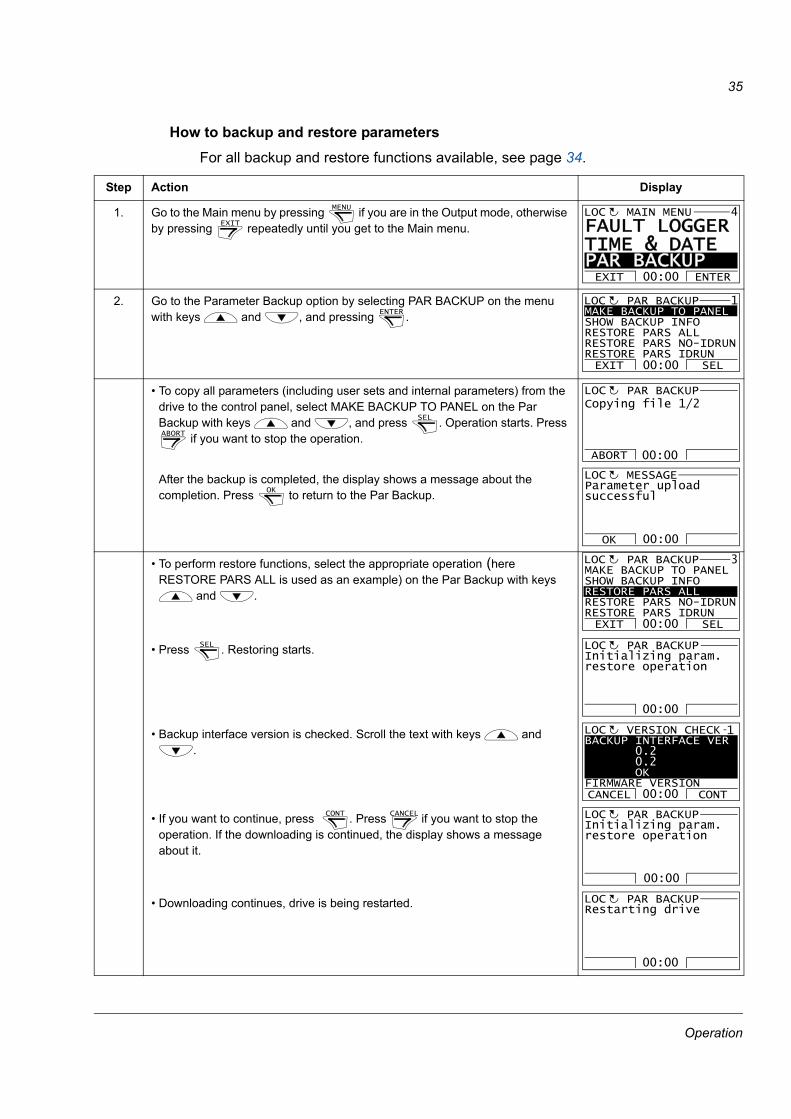
How to backup and restore parametersFor all backup and restore functions available, see page 34.
Step Action Display
1. Go to the Main menu by pressing if you are in the Output mode, otherwise by pressing repeatedly until you get to the Main menu.
2. Go to the Parameter Backup option by selecting PAR BACKUP on the menu with keys and , and pressing .
• To copy all parameters (including user sets and internal parameters) from the drive to the control panel, select MAKE BACKUP TO PANEL on the Par Backup with keys and , and press . Operation starts. Press
if you want to stop the operation.
After the backup is completed, the display shows a message about the completion. Press to return to the Par Backup.
• To perform restore functions, select the appropriate operation (here RESTORE PARS ALL is used as an example) on the Par Backup with keys
and .
• Press . Restoring starts.
• Backup interface version is checked. Scroll the text with keys and .
• If you want to continue, press . Press if you want to stop the operation. If the downloading is continued, the display shows a message about it.
• Downloading continues, drive is being restarted.
MENU
EXIT
FAULT LOGGERTIME & DATE PAR BACKUP EXIT ENTER00:00
MAIN MENU 4LOC
ENTER MAKE BACKUP TO PANELSHOW BACKUP INFORESTORE PARS ALLRESTORE PARS NO-IDRUNRESTORE PARS IDRUNEXIT SEL00:00
PAR BACKUP 1LOC
SEL
ABORT
ABORT
PAR BACKUPLOCCopying file 1/2
00:00
OK
OK
Parameter uploadsuccessful
MESSAGELOC
00:00
MAKE BACKUP TO PANELSHOW BACKUP INFORESTORE PARS ALLRESTORE PARS NO-IDRUNRESTORE PARS IDRUNEXIT SEL
PAR BACKUP 3LOC
00:00
SEL Initializing param.restore operation
PAR BACKUPLOC
00:00
BACKUP INTERFACE VER 0.2 0.2 OKFIRMWARE VERSIONCANCEL CONT
VERSION CHECKLOC 1
00:00
CONT CANCEL Initializing param.restore operation
PAR BACKUPLOC
00:00
Restarting drive
PAR BACKUPLOC
00:00
Operation
36
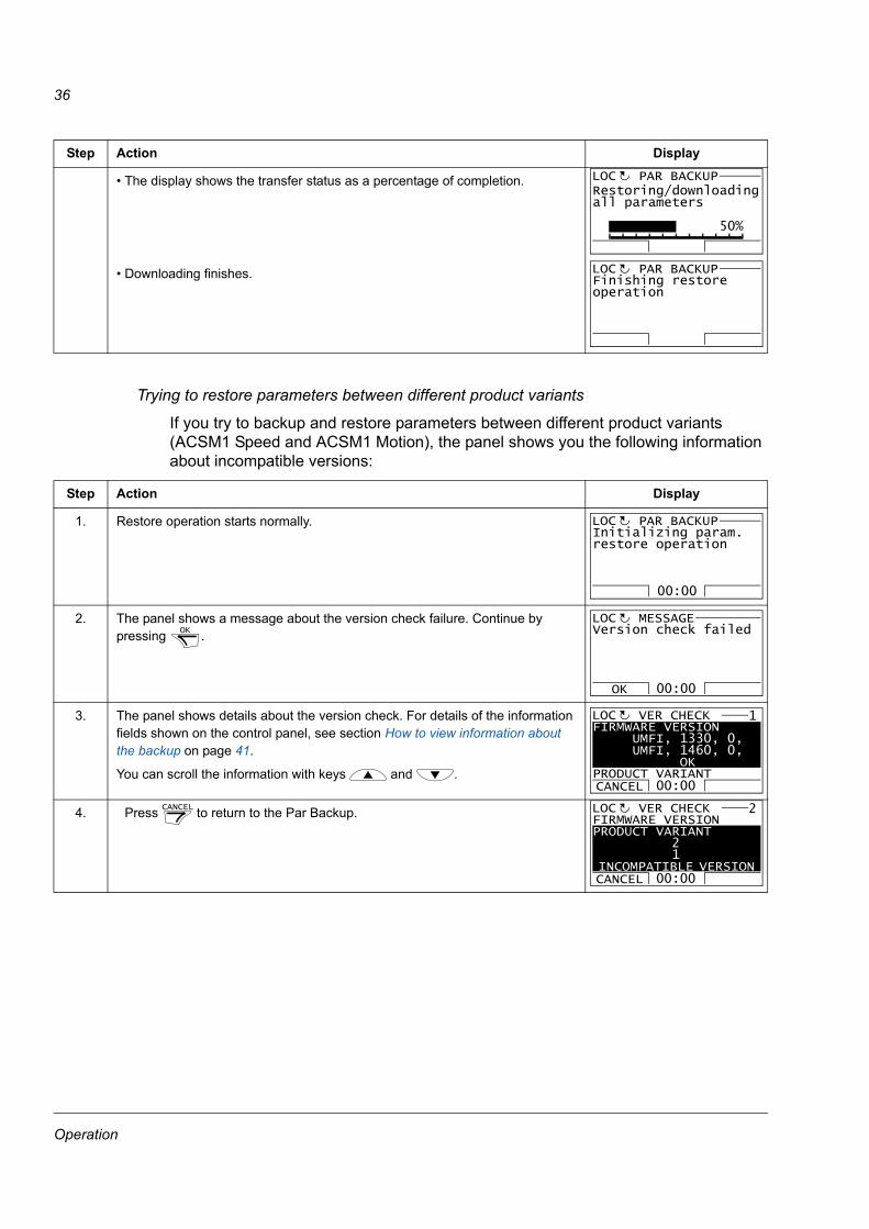
Trying to restore parameters between different product variants
If you try to backup and restore parameters between different product variants (ACSM1 Speed and ACSM1 Motion), the panel shows you the following information about incompatible versions:
• The display shows the transfer status as a percentage of completion.
• Downloading finishes.
Step Action Display
1. Restore operation starts normally.
2. The panel shows a message about the version check failure. Continue by pressing .
3. The panel shows details about the version check. For details of the information fields shown on the control panel, see section How to view information about the backup on page 41.
You can scroll the information with keys and .
4. Press to return to the Par Backup.
Step Action Display
PAR BACKUPLOC
50%
Restoring/downloadingall parameters
Finishing restoreoperation
PAR BACKUPLOC
Initializing param.restore operation
PAR BACKUPLOC
00:00
OK
OK
Version check failed
MESSAGELOC
00:00
FIRMWARE VERSION UMFI, 1330, 0, UMFI, 1460, 0, OKPRODUCT VARIANT CANCEL
VER CHECKLOC 1
00:00
CANCEL FIRMWARE VERSIONPRODUCT VARIANT 2 1 INCOMPATIBLE VERSION CANCEL
VER CHECKLOC 2
00:00
Operation
37
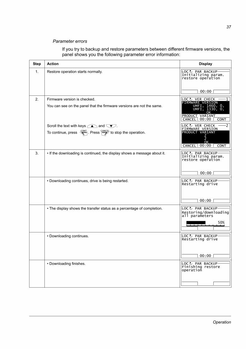
Parameter errors
If you try to backup and restore parameters between different firmware versions, the panel shows you the following parameter error information:
Step Action Display
1. Restore operation starts normally.
2. Firmware version is checked.
You can see on the panel that the firmware versions are not the same.
Scroll the text with keys and .
To continue, press . Press to stop the operation.
3. • If the downloading is continued, the display shows a message about it.
• Downloading continues, drive is being restarted.
• The display shows the transfer status as a percentage of completion.
• Downloading continues.
• Downloading finishes.
Initializing param.restore operation
PAR BACKUPLOC
00:00
CONT CANCEL
FIRMWARE VERSION UMFI, 1460, 0, UMFI, 1330, 0, OKPRODUCT VARIANT CANCEL CONT
VER CHECKLOC 1
00:00
FIRMWARE VERSIONPRODUCT VARIANT 2 2 OK CANCEL CONT
VER CHECKLOC 2
00:00
Initializing param.restore operation
PAR BACKUPLOC
00:00
Restarting drive
PAR BACKUPLOC
00:00
PAR BACKUPLOC
50%
Restoring/downloadingall parameters
Restarting drive
PAR BACKUPLOC
00:00
Finishing restoreoperation
PAR BACKUPLOC
Operation
38
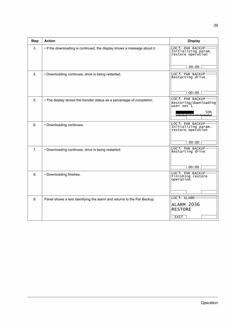
Trying to restore a user set between different firmware versions
If you try to backup and restore a user set between different firmware versions, the panel shows you the following alarm information:
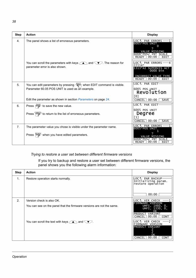
4. The panel shows a list of erroneous parameters.
You can scroll the parameters with keys and . The reason for parameter error is also shown.
5. You can edit parameters by pressing when EDIT command is visible. Parameter 60.05 POS UNIT is used as an example.
Edit the parameter as shown in section Parameters on page 24.
6. Press to save the new value.
Press to return to the list of erroneous parameters.
7. The parameter value you chose is visible under the parameter name.
Press when you have edited parameters.
Step Action Display
1. Restore operation starts normally.
2. Version check is also OK.
You can see on the panel that the firmware versions are not the same.
You can scroll the text with keys and .
Step Action Display
6005*POS UNIT 0 ? VALUE MISSING6008*POS2 INT SCALEREADY EDIT
PAR ERRORSLOC 1
00:00
22114*1313*AI SUPERVIS ACT 0000 bin INCORRECT VALUE TYPE READY EDIT
PAR ERRORSLOC 4
00:00
EDIT 6005 POS UNIT
PAR EDIT
Revolution
CANCEL SAVE00:00[0]
LOC
SAVE
CANCEL
6005 POS UNIT
PAR EDIT
Degree
CANCEL SAVE00:00[1]
LOC
READY
6005*POS UNIT 1 ? VALUE MISSING6008*POS2 INT SCALEREADY EDIT
PAR ERRORSLOC 1
00:00
Initializing param.restore operation
PAR BACKUPLOC
00:00
FIRMWARE VERSION UMFI, 1460, 0, UMFI, 1330, 0, OKPRODUCT VARIANT CANCEL CONT
VER CHECKLOC 1
00:00
FIRMWARE VERSIONPRODUCT VARIANT 2 2 OK CANCEL CONT
VER CHECKLOC 2
00:00
Operation
39
3. • If the downloading is continued, the display shows a message about it.
4. • Downloading continues, drive is being restarted.
5. • The display shows the transfer status as a percentage of completion.
6. • Downloading continues.
7. • Downloading continues, drive is being restarted.
8. • Downloading finishes.
9. Panel shows a text identifying the alarm and returns to the Par Backup.
Step Action Display
Initializing param.restore operation
PAR BACKUPLOC
00:00
Restarting drive
PAR BACKUPLOC
00:00
PAR BACKUPLOC
50%
Restoring/downloadinguser set 1
Initializing param.restore operation
PAR BACKUPLOC
00:00
Restarting drive
PAR BACKUPLOC
00:00
Finishing restoreoperation
PAR BACKUPLOC
ALARM 2036RESTORE
ALARM
EXIT
LOC
Operation
40
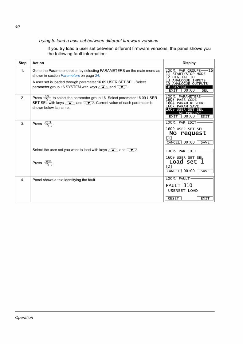
Trying to load a user set between different firmware versions
If you try load a user set between different firmware versions, the panel shows you the following fault information:
Step Action Display
1. Go to the Parameters option by selecting PARAMETERS on the main menu as shown in section Parameters on page 24.
A user set is loaded through parameter 16.09 USER SET SEL. Select parameter group 16 SYSTEM with keys and .
2. Press to select the parameter group 16. Select parameter 16.09 USER SET SEL with keys and . Current value of each parameter is shown below its name.
3. Press .
Select the user set you want to load with keys and .
Press .
4. Panel shows a text identifying the fault.
EXIT SEL00:00
11 START/STOP MODE12 DIGITAL IO13 ANALOGUE INPUTS15 ANALOGUE OUTPUTS16 SYSTEM
PAR GROUPS 16LOC
SEL 1603 PASS CODE9901 1604 PARAM RESTORE1607 PARAM SAVE1609 USER SET SEL No request
PARAMETERS
EXIT EDIT00:00
LOC
EDIT 1609 USER SET SEL
PAR EDIT
No request
CANCEL SAVE00:00[1]
LOC
SAVE
1609 USER SET SEL
PAR EDIT
Load set 1
CANCEL SAVE00:00[2]
LOC
FAULT 310 USERSET LOAD
FAULT
RESET EXIT
LOC
Operation
41
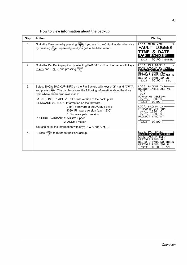
How to view information about the backup
Step Action Display
1. Go to the Main menu by pressing if you are in the Output mode, otherwise by pressing repeatedly until you get to the Main menu.
2. Go to the Par Backup option by selecting PAR BACKUP on the menu with keys and , and pressing .
3. Select SHOW BACKUP INFO on the Par Backup with keys and , and press . The display shows the following information about the drive from where the backup was made:
BACKUP INTERFACE VER: Format version of the backup file FIRMWARE VERSION: Information on the firmware
UMFI: Firmware of the ACSM1 drive1330: Firmware version (e.g. 1.330)0: Firmware patch version
PRODUCT VARIANT: 1: ACSM1 Speed 2: ACSM1 Motion
You can scroll the information with keys and .
4. Press to return to the Par Backup.
MENU
EXIT
FAULT LOGGERTIME & DATE PAR BACKUP EXIT ENTER00:00
MAIN MENU 4LOC
ENTER MAKE BACKUP TO PANELSHOW BACKUP INFORESTORE PARS ALLRESTORE PARS NO-IDRUNRESTORE PARS IDRUNEXIT SEL00:00
PAR BACKUP 2LOC
SELLOC
EXIT 00:00
BACKUP INTERFACE VER 0.2 0.2FIRMWARE VERSION UMFI, 1330, 0,
BACKUP INFO
EXIT 00:00
FIRMWARE VERSION UMFI, 1330, 0, UMFI, 1330, 0, PRODUCT VARIANT 2
BACKUP INFOLOC
EXIT MAKE BACKUP TO PANELSHOW BACKUP INFORESTORE PARS ALLRESTORE PARS NO-IDRUNRESTORE PARS IDRUNEXIT SEL00:00
PAR BACKUP 1LOC
Operation
42
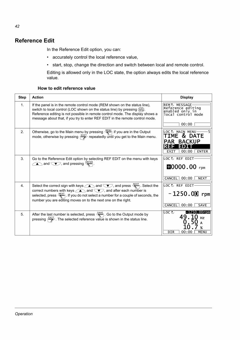
Reference EditIn the Reference Edit option, you can:
• accurately control the local reference value,
• start, stop, change the direction and switch between local and remote control.
Editing is allowed only in the LOC state, the option always edits the local reference value.
How to edit reference value
Step Action Display
1. If the panel is in the remote control mode (REM shown on the status line), switch to local control (LOC shown on the status line) by pressing . Reference editing is not possible in remote control mode. The display shows a message about that, if you try to enter REF EDIT in the remote control mode.
2. Otherwise, go to the Main menu by pressing if you are in the Output mode, otherwise by pressing repeatedly until you get to the Main menu.
3. Go to the Reference Edit option by selecting REF EDIT on the menu with keys and , and pressing .
4. Select the correct sign with keys and , and press . Select the correct numbers with keys and , and after each number is selected, press . If you do not select a number for a couple of seconds, the number you are editing moves on to the next one on the right.
5. After the last number is selected, press . Go to the Output mode by pressing . The selected reference value is shown in the status line.
LOCREM
Reference editingenabled only inlocal control mode
MESSAGEREM
00:00
MENU
EXIT
TIME & DATEPAR BACKUP REF EDITEXIT ENTER00:00
MAIN MENU 5LOC
ENTER
0000.00 rpm+
REF EDIT
CANCEL NEXT00:00
LOC
NEXT
NEXT
1250.00 rpm-
REF EDIT
CANCEL SAVE00:00
LOC
SAVE
EXIT
-1250.00rpm
50 A
10 Hz
7 %10.0.
49.LOC
DIR MENU00:00
Operation
43
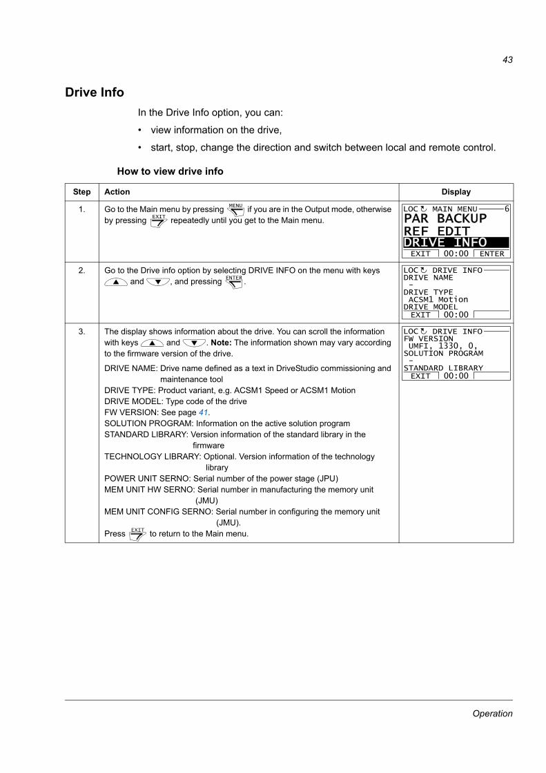
Drive InfoIn the Drive Info option, you can:
• view information on the drive,
• start, stop, change the direction and switch between local and remote control.
How to view drive info
Step Action Display
1. Go to the Main menu by pressing if you are in the Output mode, otherwise by pressing repeatedly until you get to the Main menu.
2. Go to the Drive info option by selecting DRIVE INFO on the menu with keys and , and pressing .
3. The display shows information about the drive. You can scroll the information with keys and . Note: The information shown may vary according to the firmware version of the drive.
DRIVE NAME: Drive name defined as a text in DriveStudio commissioning and maintenance tool
DRIVE TYPE: Product variant, e.g. ACSM1 Speed or ACSM1 MotionDRIVE MODEL: Type code of the driveFW VERSION: See page 41.SOLUTION PROGRAM: Information on the active solution programSTANDARD LIBRARY: Version information of the standard library in the
firmwareTECHNOLOGY LIBRARY: Optional. Version information of the technology
libraryPOWER UNIT SERNO: Serial number of the power stage (JPU)MEM UNIT HW SERNO: Serial number in manufacturing the memory unit
(JMU)MEM UNIT CONFIG SERNO: Serial number in configuring the memory unit
(JMU).Press to return to the Main menu.
MENU
EXIT
PAR BACKUPREF EDIT DRIVE INFOEXIT ENTER00:00
MAIN MENU 6LOC
ENTER
EXIT 00:00
DRIVE NAME -DRIVE TYPE ACSM1 MotionDRIVE MODEL
DRIVE INFOLOC
EXIT
EXIT 00:00
FW VERSION UMFI, 1330, 0,SOLUTION PROGRAM -STANDARD LIBRARY
DRIVE INFOLOC
Operation

44
Operation


3AU
A00
0002
0131
Rev
B /
EN
EFF
EC
TIV
E: 2
009-
08-1
2
ABB OyAC DrivesP.O. Box 184FI-00381 HELSINKIFINLANDTelephone +358 10 22 11Fax +358 10 22 22681Internet www.abb.com