Embed Size (px)
Citation preview

ABB machinery drives
SupplementWinder control program for ACSM1 drives
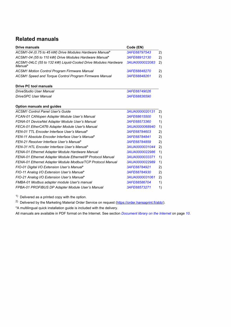
Related manuals
1) Delivered as a printed copy with the option.2) Delivered by the Marketing Material Order Service on request (https://order.hansaprint.fi/abb/).*A multilingual quick installation guide is included with the delivery.All manuals are available in PDF format on the Internet. See section Document library on the Internet on page 10.
Drive manuals Code (EN)ACSM1-04 (0.75 to 45 kW) Drive Modules Hardware Manual* 3AFE68797543 2)ACSM1-04 (55 to 110 kW) Drive Modules Hardware Manual* 3AFE68912130 2)ACSM1-04LC (55 to 132 kW) Liquid-Cooled Drive Modules Hardware Manual*
3AUA0000022083 2)
ACSM1 Motion Control Program Firmware Manual 3AFE68848270 2)ACSM1 Speed and Torque Control Program Firmware Manual 3AFE68848261 2)
Drive PC tool manualsDriveStudio User Manual 3AFE68749026DriveSPC User Manual 3AFE68836590
Option manuals and guidesACSM1 Control Panel User's Guide 3AUA0000020131 2)FCAN-01 CANopen Adapter Module User’s Manual 3AFE68615500 1)FDNA-01 DeviceNet Adapter Module User’s Manual 3AFE68573360 1)FECA-01 EtherCAT® Adapter Module User's Manual 3AUA0000068940 1)FEN-01 TTL Encoder Interface User’s Manual* 3AFE68784603 2)FEN-11 Absolute Encoder Interface User’s Manual* 3AFE68784841 2)FEN-21 Resolver Interface User’s Manual* 3AFE68784859 2)FEN-31 HTL Encoder Interface User’s Manual* 3AUA0000031044 2)FENA-01 Ethernet Adapter Module Hardware Manual 3AUA0000022986 1)FENA-01 Ethernet Adapter Module Ethernet/IP Protocol Manual 3AUA0000033371 1)FENA-01 Ethernet Adapter Module Modbus/TCP Protocol Manual 3AUA0000022989 1)FIO-01 Digital I/O Extension User’s Manual* 3AFE68784921 2)FIO-11 Analog I/O Extension User’s Manual* 3AFE68784930 2)FIO-21 Analog I/O Extension User’s Manual* 3AUA0000031061 2)FMBA-01 Modbus adapter module User's manual 3AFE68586704 1)FPBA-01 PROFIBUS DP Adapter Module User’s Manual 3AFE68573271 1)

Winder control program for ACSM1 drives
Supplement
3AUA0000031510 REV CEN
EFFECTIVE: 2010-08-16
© 2010 ABB Oy. All Rights Reserved.

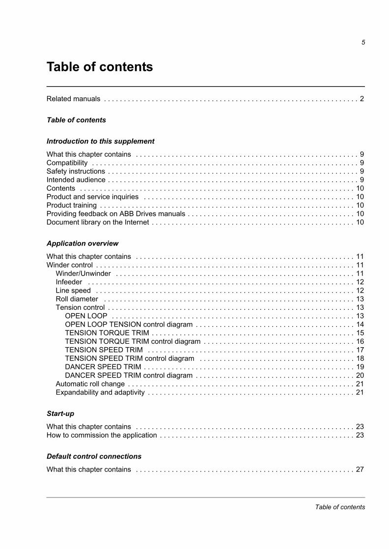
5
Table of contents
Related manuals . . . . . . . . . . . . . . . . . . . . . . . . . . . . . . . . . . . . . . . . . . . . . . . . . . . . . . . . . . . . . . . . 2
Table of contents
Introduction to this supplement
What this chapter contains . . . . . . . . . . . . . . . . . . . . . . . . . . . . . . . . . . . . . . . . . . . . . . . . . . . . . . . . 9Compatibility . . . . . . . . . . . . . . . . . . . . . . . . . . . . . . . . . . . . . . . . . . . . . . . . . . . . . . . . . . . . . . . . . . . 9Safety instructions . . . . . . . . . . . . . . . . . . . . . . . . . . . . . . . . . . . . . . . . . . . . . . . . . . . . . . . . . . . . . . . 9Intended audience . . . . . . . . . . . . . . . . . . . . . . . . . . . . . . . . . . . . . . . . . . . . . . . . . . . . . . . . . . . . . . . 9Contents . . . . . . . . . . . . . . . . . . . . . . . . . . . . . . . . . . . . . . . . . . . . . . . . . . . . . . . . . . . . . . . . . . . . . 10Product and service inquiries . . . . . . . . . . . . . . . . . . . . . . . . . . . . . . . . . . . . . . . . . . . . . . . . . . . . . 10Product training . . . . . . . . . . . . . . . . . . . . . . . . . . . . . . . . . . . . . . . . . . . . . . . . . . . . . . . . . . . . . . . . 10Providing feedback on ABB Drives manuals . . . . . . . . . . . . . . . . . . . . . . . . . . . . . . . . . . . . . . . . . . 10Document library on the Internet . . . . . . . . . . . . . . . . . . . . . . . . . . . . . . . . . . . . . . . . . . . . . . . . . . . 10
Application overview
What this chapter contains . . . . . . . . . . . . . . . . . . . . . . . . . . . . . . . . . . . . . . . . . . . . . . . . . . . . . . . 11Winder control . . . . . . . . . . . . . . . . . . . . . . . . . . . . . . . . . . . . . . . . . . . . . . . . . . . . . . . . . . . . . . . . . 11
Winder/Unwinder . . . . . . . . . . . . . . . . . . . . . . . . . . . . . . . . . . . . . . . . . . . . . . . . . . . . . . . . . . . . 11Infeeder . . . . . . . . . . . . . . . . . . . . . . . . . . . . . . . . . . . . . . . . . . . . . . . . . . . . . . . . . . . . . . . . . . . 12Line speed . . . . . . . . . . . . . . . . . . . . . . . . . . . . . . . . . . . . . . . . . . . . . . . . . . . . . . . . . . . . . . . . . 12Roll diameter . . . . . . . . . . . . . . . . . . . . . . . . . . . . . . . . . . . . . . . . . . . . . . . . . . . . . . . . . . . . . . . 13Tension control . . . . . . . . . . . . . . . . . . . . . . . . . . . . . . . . . . . . . . . . . . . . . . . . . . . . . . . . . . . . . . 13
OPEN LOOP . . . . . . . . . . . . . . . . . . . . . . . . . . . . . . . . . . . . . . . . . . . . . . . . . . . . . . . . . . . . . 13OPEN LOOP TENSION control diagram . . . . . . . . . . . . . . . . . . . . . . . . . . . . . . . . . . . . . . . . 14TENSION TORQUE TRIM . . . . . . . . . . . . . . . . . . . . . . . . . . . . . . . . . . . . . . . . . . . . . . . . . . . 15TENSION TORQUE TRIM control diagram . . . . . . . . . . . . . . . . . . . . . . . . . . . . . . . . . . . . . . 16TENSION SPEED TRIM . . . . . . . . . . . . . . . . . . . . . . . . . . . . . . . . . . . . . . . . . . . . . . . . . . . . 17TENSION SPEED TRIM control diagram . . . . . . . . . . . . . . . . . . . . . . . . . . . . . . . . . . . . . . . 18DANCER SPEED TRIM . . . . . . . . . . . . . . . . . . . . . . . . . . . . . . . . . . . . . . . . . . . . . . . . . . . . . 19DANCER SPEED TRIM control diagram . . . . . . . . . . . . . . . . . . . . . . . . . . . . . . . . . . . . . . . . 20
Automatic roll change . . . . . . . . . . . . . . . . . . . . . . . . . . . . . . . . . . . . . . . . . . . . . . . . . . . . . . . . . 21Expandability and adaptivity . . . . . . . . . . . . . . . . . . . . . . . . . . . . . . . . . . . . . . . . . . . . . . . . . . . . 21
Start-up
What this chapter contains . . . . . . . . . . . . . . . . . . . . . . . . . . . . . . . . . . . . . . . . . . . . . . . . . . . . . . . 23How to commission the application . . . . . . . . . . . . . . . . . . . . . . . . . . . . . . . . . . . . . . . . . . . . . . . . . 23
Default control connections
What this chapter contains . . . . . . . . . . . . . . . . . . . . . . . . . . . . . . . . . . . . . . . . . . . . . . . . . . . . . . . 27
Table of contents
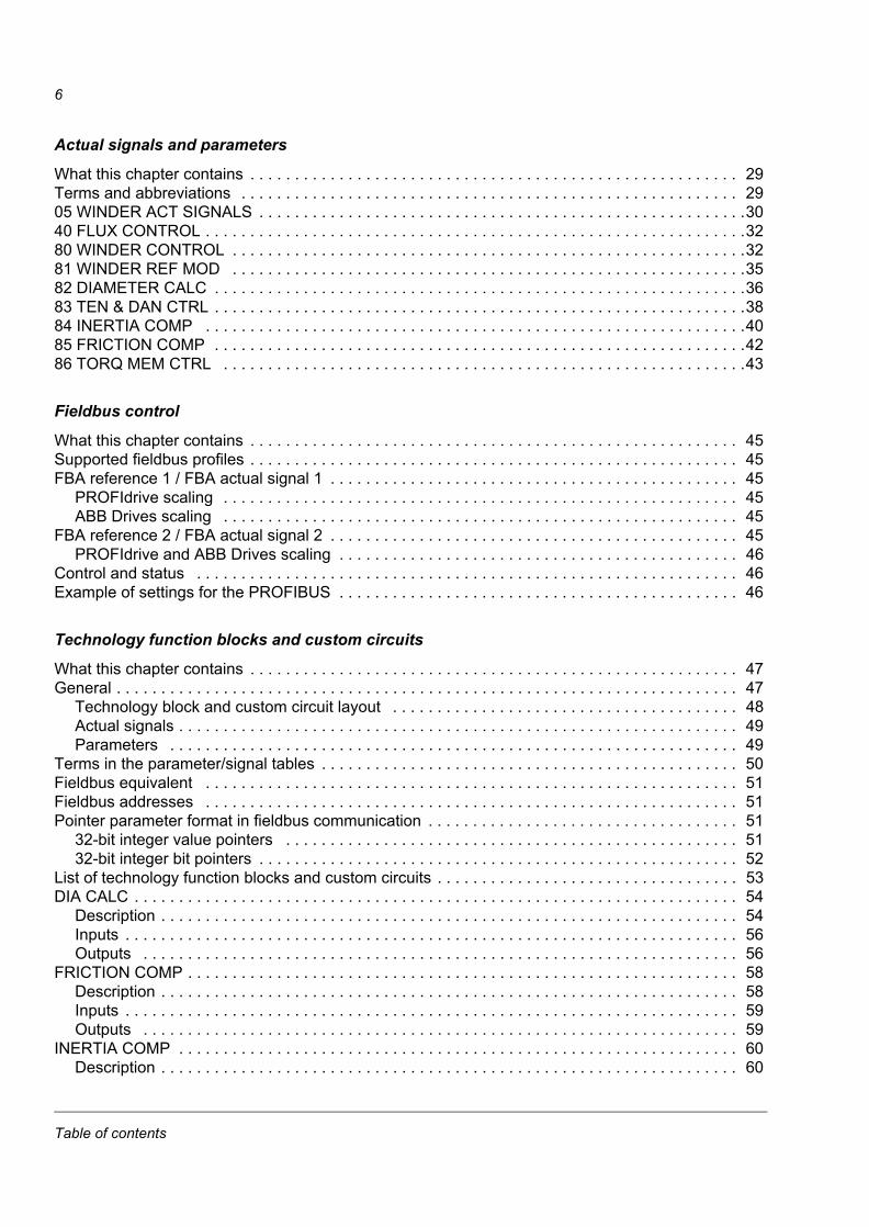
6
Actual signals and parameters
What this chapter contains . . . . . . . . . . . . . . . . . . . . . . . . . . . . . . . . . . . . . . . . . . . . . . . . . . . . . . . 29Terms and abbreviations . . . . . . . . . . . . . . . . . . . . . . . . . . . . . . . . . . . . . . . . . . . . . . . . . . . . . . . . 2905 WINDER ACT SIGNALS . . . . . . . . . . . . . . . . . . . . . . . . . . . . . . . . . . . . . . . . . . . . . . . . . . . . . . .3040 FLUX CONTROL . . . . . . . . . . . . . . . . . . . . . . . . . . . . . . . . . . . . . . . . . . . . . . . . . . . . . . . . . . . . .3280 WINDER CONTROL . . . . . . . . . . . . . . . . . . . . . . . . . . . . . . . . . . . . . . . . . . . . . . . . . . . . . . . . . .3281 WINDER REF MOD . . . . . . . . . . . . . . . . . . . . . . . . . . . . . . . . . . . . . . . . . . . . . . . . . . . . . . . . . .3582 DIAMETER CALC . . . . . . . . . . . . . . . . . . . . . . . . . . . . . . . . . . . . . . . . . . . . . . . . . . . . . . . . . . . .3683 TEN & DAN CTRL . . . . . . . . . . . . . . . . . . . . . . . . . . . . . . . . . . . . . . . . . . . . . . . . . . . . . . . . . . . .3884 INERTIA COMP . . . . . . . . . . . . . . . . . . . . . . . . . . . . . . . . . . . . . . . . . . . . . . . . . . . . . . . . . . . . .4085 FRICTION COMP . . . . . . . . . . . . . . . . . . . . . . . . . . . . . . . . . . . . . . . . . . . . . . . . . . . . . . . . . . . .4286 TORQ MEM CTRL . . . . . . . . . . . . . . . . . . . . . . . . . . . . . . . . . . . . . . . . . . . . . . . . . . . . . . . . . . .43
Fieldbus control
What this chapter contains . . . . . . . . . . . . . . . . . . . . . . . . . . . . . . . . . . . . . . . . . . . . . . . . . . . . . . . 45Supported fieldbus profiles . . . . . . . . . . . . . . . . . . . . . . . . . . . . . . . . . . . . . . . . . . . . . . . . . . . . . . . 45FBA reference 1 / FBA actual signal 1 . . . . . . . . . . . . . . . . . . . . . . . . . . . . . . . . . . . . . . . . . . . . . . 45
PROFIdrive scaling . . . . . . . . . . . . . . . . . . . . . . . . . . . . . . . . . . . . . . . . . . . . . . . . . . . . . . . . . . 45ABB Drives scaling . . . . . . . . . . . . . . . . . . . . . . . . . . . . . . . . . . . . . . . . . . . . . . . . . . . . . . . . . . 45
FBA reference 2 / FBA actual signal 2 . . . . . . . . . . . . . . . . . . . . . . . . . . . . . . . . . . . . . . . . . . . . . . 45PROFIdrive and ABB Drives scaling . . . . . . . . . . . . . . . . . . . . . . . . . . . . . . . . . . . . . . . . . . . . . 46
Control and status . . . . . . . . . . . . . . . . . . . . . . . . . . . . . . . . . . . . . . . . . . . . . . . . . . . . . . . . . . . . . 46Example of settings for the PROFIBUS . . . . . . . . . . . . . . . . . . . . . . . . . . . . . . . . . . . . . . . . . . . . . 46
Technology function blocks and custom circuits
What this chapter contains . . . . . . . . . . . . . . . . . . . . . . . . . . . . . . . . . . . . . . . . . . . . . . . . . . . . . . . 47General . . . . . . . . . . . . . . . . . . . . . . . . . . . . . . . . . . . . . . . . . . . . . . . . . . . . . . . . . . . . . . . . . . . . . . 47
Technology block and custom circuit layout . . . . . . . . . . . . . . . . . . . . . . . . . . . . . . . . . . . . . . . 48Actual signals . . . . . . . . . . . . . . . . . . . . . . . . . . . . . . . . . . . . . . . . . . . . . . . . . . . . . . . . . . . . . . . 49Parameters . . . . . . . . . . . . . . . . . . . . . . . . . . . . . . . . . . . . . . . . . . . . . . . . . . . . . . . . . . . . . . . . 49
Terms in the parameter/signal tables . . . . . . . . . . . . . . . . . . . . . . . . . . . . . . . . . . . . . . . . . . . . . . . 50Fieldbus equivalent . . . . . . . . . . . . . . . . . . . . . . . . . . . . . . . . . . . . . . . . . . . . . . . . . . . . . . . . . . . . 51Fieldbus addresses . . . . . . . . . . . . . . . . . . . . . . . . . . . . . . . . . . . . . . . . . . . . . . . . . . . . . . . . . . . . 51Pointer parameter format in fieldbus communication . . . . . . . . . . . . . . . . . . . . . . . . . . . . . . . . . . . 51
32-bit integer value pointers . . . . . . . . . . . . . . . . . . . . . . . . . . . . . . . . . . . . . . . . . . . . . . . . . . . 5132-bit integer bit pointers . . . . . . . . . . . . . . . . . . . . . . . . . . . . . . . . . . . . . . . . . . . . . . . . . . . . . . 52
List of technology function blocks and custom circuits . . . . . . . . . . . . . . . . . . . . . . . . . . . . . . . . . . 53DIA CALC . . . . . . . . . . . . . . . . . . . . . . . . . . . . . . . . . . . . . . . . . . . . . . . . . . . . . . . . . . . . . . . . . . . . 54
Description . . . . . . . . . . . . . . . . . . . . . . . . . . . . . . . . . . . . . . . . . . . . . . . . . . . . . . . . . . . . . . . . . 54Inputs . . . . . . . . . . . . . . . . . . . . . . . . . . . . . . . . . . . . . . . . . . . . . . . . . . . . . . . . . . . . . . . . . . . . . 56Outputs . . . . . . . . . . . . . . . . . . . . . . . . . . . . . . . . . . . . . . . . . . . . . . . . . . . . . . . . . . . . . . . . . . . 56
FRICTION COMP . . . . . . . . . . . . . . . . . . . . . . . . . . . . . . . . . . . . . . . . . . . . . . . . . . . . . . . . . . . . . . 58Description . . . . . . . . . . . . . . . . . . . . . . . . . . . . . . . . . . . . . . . . . . . . . . . . . . . . . . . . . . . . . . . . . 58Inputs . . . . . . . . . . . . . . . . . . . . . . . . . . . . . . . . . . . . . . . . . . . . . . . . . . . . . . . . . . . . . . . . . . . . . 59Outputs . . . . . . . . . . . . . . . . . . . . . . . . . . . . . . . . . . . . . . . . . . . . . . . . . . . . . . . . . . . . . . . . . . . 59
INERTIA COMP . . . . . . . . . . . . . . . . . . . . . . . . . . . . . . . . . . . . . . . . . . . . . . . . . . . . . . . . . . . . . . . 60Description . . . . . . . . . . . . . . . . . . . . . . . . . . . . . . . . . . . . . . . . . . . . . . . . . . . . . . . . . . . . . . . . . 60
Table of contents

7
Inputs . . . . . . . . . . . . . . . . . . . . . . . . . . . . . . . . . . . . . . . . . . . . . . . . . . . . . . . . . . . . . . . . . . . . . 62Outputs . . . . . . . . . . . . . . . . . . . . . . . . . . . . . . . . . . . . . . . . . . . . . . . . . . . . . . . . . . . . . . . . . . . . 62
TEN&DAN CTRL . . . . . . . . . . . . . . . . . . . . . . . . . . . . . . . . . . . . . . . . . . . . . . . . . . . . . . . . . . . . . . . 63Description . . . . . . . . . . . . . . . . . . . . . . . . . . . . . . . . . . . . . . . . . . . . . . . . . . . . . . . . . . . . . . . . . 63Inputs . . . . . . . . . . . . . . . . . . . . . . . . . . . . . . . . . . . . . . . . . . . . . . . . . . . . . . . . . . . . . . . . . . . . . 65Outputs . . . . . . . . . . . . . . . . . . . . . . . . . . . . . . . . . . . . . . . . . . . . . . . . . . . . . . . . . . . . . . . . . . . . 65
NCTRLTORQLIMSEL . . . . . . . . . . . . . . . . . . . . . . . . . . . . . . . . . . . . . . . . . . . . . . . . . . . . . . . . . . . 66Description . . . . . . . . . . . . . . . . . . . . . . . . . . . . . . . . . . . . . . . . . . . . . . . . . . . . . . . . . . . . . . . . . 66Inputs . . . . . . . . . . . . . . . . . . . . . . . . . . . . . . . . . . . . . . . . . . . . . . . . . . . . . . . . . . . . . . . . . . . . . 67Outputs . . . . . . . . . . . . . . . . . . . . . . . . . . . . . . . . . . . . . . . . . . . . . . . . . . . . . . . . . . . . . . . . . . . . 67
TEN2SPD . . . . . . . . . . . . . . . . . . . . . . . . . . . . . . . . . . . . . . . . . . . . . . . . . . . . . . . . . . . . . . . . . . . . 68Description . . . . . . . . . . . . . . . . . . . . . . . . . . . . . . . . . . . . . . . . . . . . . . . . . . . . . . . . . . . . . . . . . 69Inputs . . . . . . . . . . . . . . . . . . . . . . . . . . . . . . . . . . . . . . . . . . . . . . . . . . . . . . . . . . . . . . . . . . . . . 69Outputs . . . . . . . . . . . . . . . . . . . . . . . . . . . . . . . . . . . . . . . . . . . . . . . . . . . . . . . . . . . . . . . . . . . . 69
TEN2TORQ . . . . . . . . . . . . . . . . . . . . . . . . . . . . . . . . . . . . . . . . . . . . . . . . . . . . . . . . . . . . . . . . . . . 70Description . . . . . . . . . . . . . . . . . . . . . . . . . . . . . . . . . . . . . . . . . . . . . . . . . . . . . . . . . . . . . . . . . 71Inputs . . . . . . . . . . . . . . . . . . . . . . . . . . . . . . . . . . . . . . . . . . . . . . . . . . . . . . . . . . . . . . . . . . . . . 71Outputs . . . . . . . . . . . . . . . . . . . . . . . . . . . . . . . . . . . . . . . . . . . . . . . . . . . . . . . . . . . . . . . . . . . . 71
TORQMEM . . . . . . . . . . . . . . . . . . . . . . . . . . . . . . . . . . . . . . . . . . . . . . . . . . . . . . . . . . . . . . . . . . . 72Description . . . . . . . . . . . . . . . . . . . . . . . . . . . . . . . . . . . . . . . . . . . . . . . . . . . . . . . . . . . . . . . . . 72Inputs . . . . . . . . . . . . . . . . . . . . . . . . . . . . . . . . . . . . . . . . . . . . . . . . . . . . . . . . . . . . . . . . . . . . . 73Outputs . . . . . . . . . . . . . . . . . . . . . . . . . . . . . . . . . . . . . . . . . . . . . . . . . . . . . . . . . . . . . . . . . . . . 73
WEBLOSS . . . . . . . . . . . . . . . . . . . . . . . . . . . . . . . . . . . . . . . . . . . . . . . . . . . . . . . . . . . . . . . . . . . . 74Description . . . . . . . . . . . . . . . . . . . . . . . . . . . . . . . . . . . . . . . . . . . . . . . . . . . . . . . . . . . . . . . . . 75Inputs . . . . . . . . . . . . . . . . . . . . . . . . . . . . . . . . . . . . . . . . . . . . . . . . . . . . . . . . . . . . . . . . . . . . . 75Outputs . . . . . . . . . . . . . . . . . . . . . . . . . . . . . . . . . . . . . . . . . . . . . . . . . . . . . . . . . . . . . . . . . . . . 75
WINDERCTRL . . . . . . . . . . . . . . . . . . . . . . . . . . . . . . . . . . . . . . . . . . . . . . . . . . . . . . . . . . . . . . . . 76Description . . . . . . . . . . . . . . . . . . . . . . . . . . . . . . . . . . . . . . . . . . . . . . . . . . . . . . . . . . . . . . . . . 76Inputs . . . . . . . . . . . . . . . . . . . . . . . . . . . . . . . . . . . . . . . . . . . . . . . . . . . . . . . . . . . . . . . . . . . . . 76Outputs . . . . . . . . . . . . . . . . . . . . . . . . . . . . . . . . . . . . . . . . . . . . . . . . . . . . . . . . . . . . . . . . . . . . 76
WINDERREFMOD . . . . . . . . . . . . . . . . . . . . . . . . . . . . . . . . . . . . . . . . . . . . . . . . . . . . . . . . . . . . . 77Description . . . . . . . . . . . . . . . . . . . . . . . . . . . . . . . . . . . . . . . . . . . . . . . . . . . . . . . . . . . . . . . . . 77Inputs . . . . . . . . . . . . . . . . . . . . . . . . . . . . . . . . . . . . . . . . . . . . . . . . . . . . . . . . . . . . . . . . . . . . . 78Outputs . . . . . . . . . . . . . . . . . . . . . . . . . . . . . . . . . . . . . . . . . . . . . . . . . . . . . . . . . . . . . . . . . . . . 78
WINDERSTALL . . . . . . . . . . . . . . . . . . . . . . . . . . . . . . . . . . . . . . . . . . . . . . . . . . . . . . . . . . . . . . . . 79Description . . . . . . . . . . . . . . . . . . . . . . . . . . . . . . . . . . . . . . . . . . . . . . . . . . . . . . . . . . . . . . . . . 80Inputs . . . . . . . . . . . . . . . . . . . . . . . . . . . . . . . . . . . . . . . . . . . . . . . . . . . . . . . . . . . . . . . . . . . . . 80Outputs . . . . . . . . . . . . . . . . . . . . . . . . . . . . . . . . . . . . . . . . . . . . . . . . . . . . . . . . . . . . . . . . . . . . 80
FLUX CTRL . . . . . . . . . . . . . . . . . . . . . . . . . . . . . . . . . . . . . . . . . . . . . . . . . . . . . . . . . . . . . . . . . . . 81Description . . . . . . . . . . . . . . . . . . . . . . . . . . . . . . . . . . . . . . . . . . . . . . . . . . . . . . . . . . . . . . . . . 81Inputs . . . . . . . . . . . . . . . . . . . . . . . . . . . . . . . . . . . . . . . . . . . . . . . . . . . . . . . . . . . . . . . . . . . . . 82Outputs . . . . . . . . . . . . . . . . . . . . . . . . . . . . . . . . . . . . . . . . . . . . . . . . . . . . . . . . . . . . . . . . . . . . 82
Fault tracing
What this chapter contains . . . . . . . . . . . . . . . . . . . . . . . . . . . . . . . . . . . . . . . . . . . . . . . . . . . . . . . 83Safety . . . . . . . . . . . . . . . . . . . . . . . . . . . . . . . . . . . . . . . . . . . . . . . . . . . . . . . . . . . . . . . . . . . . . . . 83Alarm and fault indications . . . . . . . . . . . . . . . . . . . . . . . . . . . . . . . . . . . . . . . . . . . . . . . . . . . . . . . 83How to reset . . . . . . . . . . . . . . . . . . . . . . . . . . . . . . . . . . . . . . . . . . . . . . . . . . . . . . . . . . . . . . . . . . 83Fault history . . . . . . . . . . . . . . . . . . . . . . . . . . . . . . . . . . . . . . . . . . . . . . . . . . . . . . . . . . . . . . . . . . . 84
Table of contents
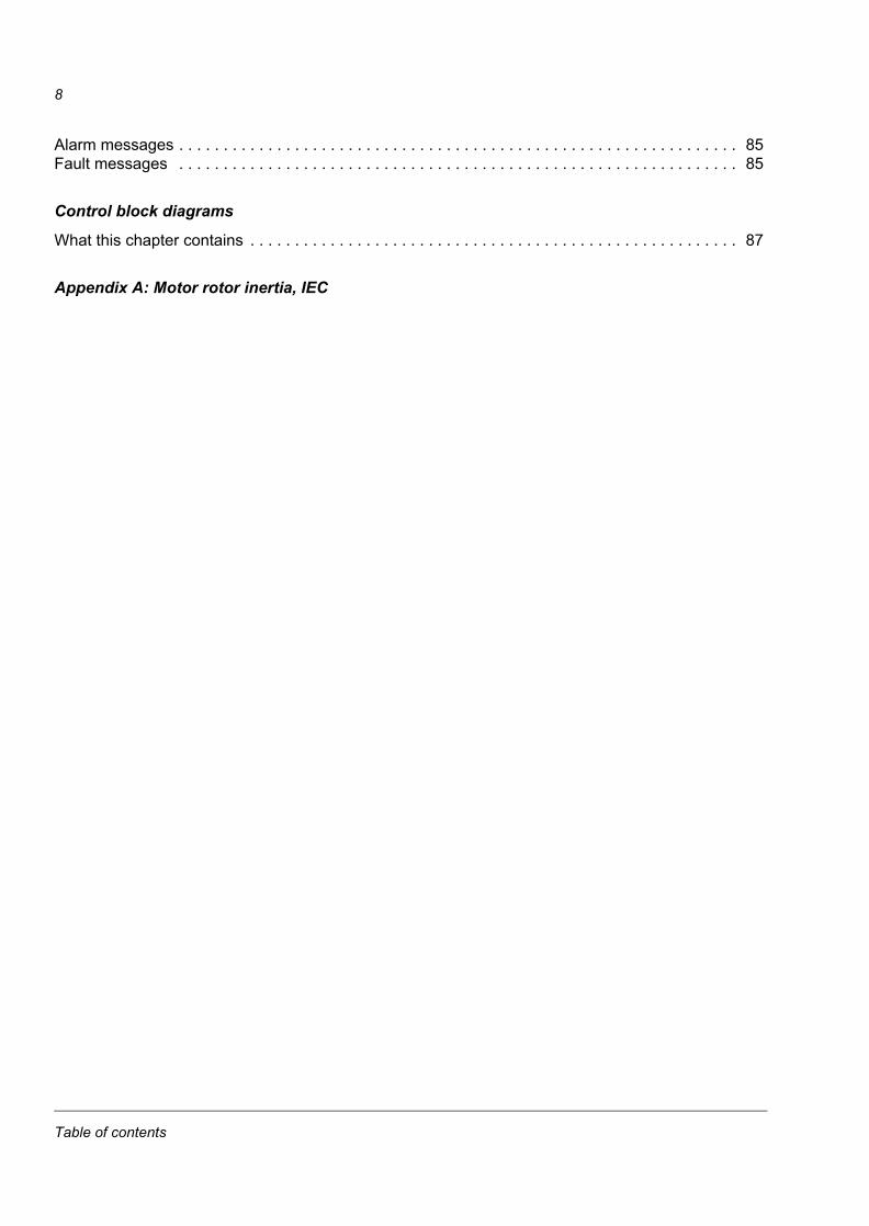
8
Alarm messages . . . . . . . . . . . . . . . . . . . . . . . . . . . . . . . . . . . . . . . . . . . . . . . . . . . . . . . . . . . . . . . 85Fault messages . . . . . . . . . . . . . . . . . . . . . . . . . . . . . . . . . . . . . . . . . . . . . . . . . . . . . . . . . . . . . . . 85
Control block diagrams
What this chapter contains . . . . . . . . . . . . . . . . . . . . . . . . . . . . . . . . . . . . . . . . . . . . . . . . . . . . . . . 87
Appendix A: Motor rotor inertia, IEC
Table of contents
9
Introduction to this supplement
This document is a supplement to ACSM1 Speed and Torque Control Program Firmware Manual (3AFE68848261 [English]). The supplement covers actual signals, parameters, technology function blocks, custom circuits as well as fault and alarm messages related to the winder control program. For other information, refer to the Firmware Manual.
What this chapter containsThe chapter includes a description of the contents of the supplement. In addition, it contains information about the compatibility, safety and intended audience.
CompatibilityThe supplement is compatible with the winder control program for ACSM1 drives (Version UAWI1100 and above).
Safety instructionsFollow all safety instructions delivered with the drive.
• Read the complete safety instructions before you install, commission, or use the drive. The complete safety instructions are given at the beginning of the drive Hardware Manual (see the list of related manuals on the inside of the front cover, page 2).
• Read the winder control program specific warnings and notes before changing the default settings of the parameters and functions. For each parameter, the warnings and notes are given in chapter Actual signals and parameters.
• Read the firmware function block specific warnings and notes before changing the default settings of the function. For each firmware function block, the warnings and notes are given in the drive Firmware Manual in the section describing the related user-adjustable parameters.
Intended audienceThe reader of the supplement is expected to:
• know the standard electrical wiring practices, electronic components and electrical schematic symbols
• have a firm understanding of winding and unwinding principles.
Introduction to this supplement

10
ContentsThe supplement consists of the following chapters:
• Introduction to this supplement describes the contents of this manual.
• Application overview gives a brief overview of the winder application and related terms.
• Start-up gives instructions for commissioning the winder application.
• Default control connections shows the default control connections of the JCU Control Unit.
• Actual signals and parameters describes the actual signals and parameters of the winder application.
• Technology function blocks and custom circuits describes the technology function blocks and custom circuits and lists the associated input and output parameters and signals.
• Fault tracing lists the alarms and fault messages with the possible causes and remedies.
• Control block diagrams presents the application program pages containing the winder control program technology blocks and custom circuits.
• Appendix A: Motor rotor inertia, IEC gives an example of common inverter duty AC motor rotor inertia.
Product and service inquiriesAddress any inquiries about the product to your local ABB representative, quoting the type designation and serial number of the unit in question. A listing of ABB sales, support and service contacts can be found by navigating to www.abb.com/drives and selecting Sales, Support and Service Network.
Product trainingFor information on ABB product training, navigate to www.abb.com/drives and select Training courses.
Providing feedback on ABB Drives manualsYour comments on our manuals are welcome. Go to www.abb.com/drives and select Document Library – Manuals feedback form (LV AC drives).
Document library on the InternetYou can find manuals and other product documents in PDF format on the Internet. Go to www.abb.com/drives and select Document Library. You can browse the library or enter selection criteria, for example a document code, in the search field.
Introduction to this supplement
11
Application overview
What this chapter containsThe chapter includes a brief overview of the winder application and related terms.
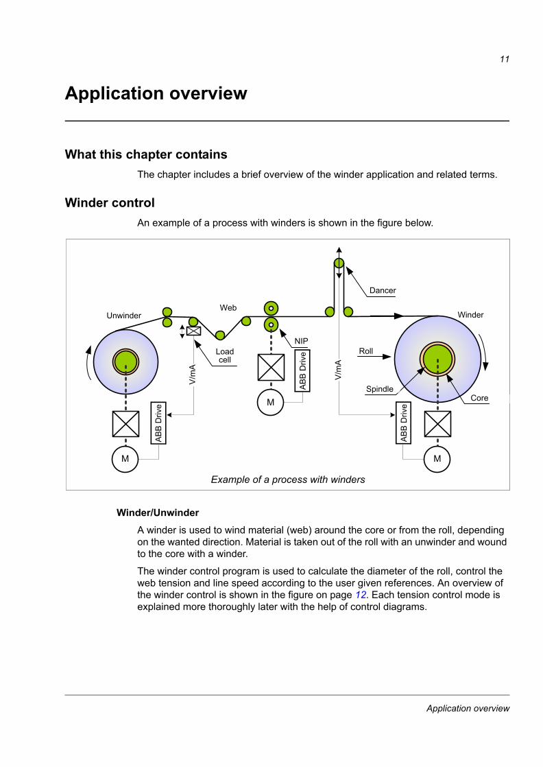
Winder controlAn example of a process with winders is shown in the figure below.
Winder/UnwinderA winder is used to wind material (web) around the core or from the roll, depending on the wanted direction. Material is taken out of the roll with an unwinder and wound to the core with a winder.
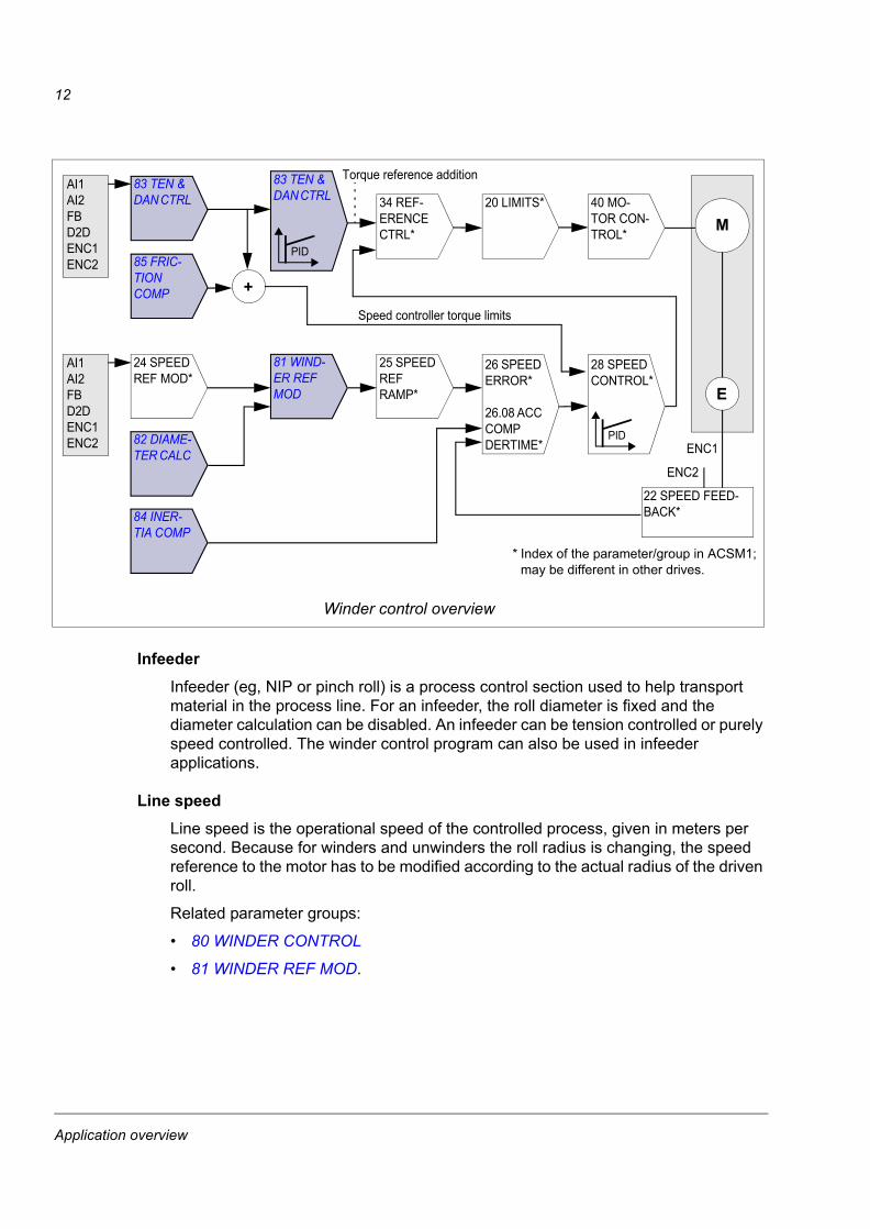
The winder control program is used to calculate the diameter of the roll, control the web tension and line speed according to the user given references. An overview of the winder control is shown in the figure on page 12. Each tension control mode is explained more thoroughly later with the help of control diagrams.
� �
�
RollNIP
Winder
Core
WebUnwinder
Dancer
Example of a process with winders
Spindle
Loadcell
V/m
A
V/m
A
AB
B D
rive
AB
B D
rive
AB
B D
rive
Application overview
12
InfeederInfeeder (eg, NIP or pinch roll) is a process control section used to help transport material in the process line. For an infeeder, the roll diameter is fixed and the diameter calculation can be disabled. An infeeder can be tension controlled or purely speed controlled. The winder control program can also be used in infeeder applications.
Line speedLine speed is the operational speed of the controlled process, given in meters per second. Because for winders and unwinders the roll radius is changing, the speed reference to the motor has to be modified according to the actual radius of the driven roll.
Related parameter groups:
• 80 WINDER CONTROL
• 81 WINDER REF MOD.
24 SPEED REF MOD*
83 TEN & DAN CTRL 20 LIMITS*
M
E
22 SPEED FEED-BACK*
+
25 SPEED REF RAMP*
26 SPEED ERROR*
26.08 ACC COMP DERTIME*
28 SPEED CONTROL*
* Index of the parameter/group in ACSM1;may be different in other drives.
ENC1
ENC2
Winder control overview
AI1AI2FBD2DENC1ENC2
Torque reference addition
Speed controller torque limits
40 MO-TOR CON-TROL*
34 REF-ERENCE CTRL*
AI1AI2FBD2DENC1ENC2
85 FRIC-TION COMP
82 DIAME-TER CALC
84 INER-TIA COMP
81 WIND-ER REF MOD
83 TEN & DAN CTRL
PID
PID
Application overview
13
Roll diameterThe winder control program uses the line speed reference and actual roll rpm to calculate the roll diameter. To stabilize the calculation, the actual diameter is ramped according to the web thickness. The roll diameter calculation is based upon internal calculations where no external device is needed; however, the use of an external diameter sensor is available. This aids in stopping and restarting partial rolls with minimal tension disturbances.
For an NIP or pinch roll (infeeders), the diameter of the driven roll does not change, so that the diameter calculation can be disabled.
Related parameter group:
• 82 DIAMETER CALC.
Tension controlThe objective of the tension control is to maintain the tension of the web, ie, the force applied to the web. The motor speed and torque must change as a function of the web speed and roll diameter.
Motor torque = Tension reference × Roll radius
The following tension control modes are available:
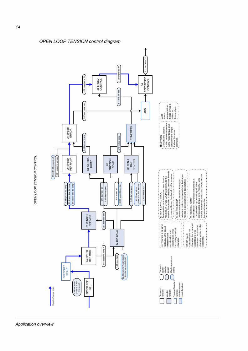
OPEN LOOP
Feedback from the web is not required in this mode. The tension of the web is controlled by calculating the torque reference of the motor, which is the product of the user-given tension reference and the actual roll radius. The tension control PID is disabled. Inertia and friction compensation can be used to improve the tension control accuracy.
The drive is running as speed controlled; the torque limits of the speed controller are controlled by the tension control. To ensure that the drive is always running against the calculated speed controller torque limits, the application adds an overspeed reference to the final speed reference. The amount of overspeed reference is adaptable with parameters.
Since tension feedback from the web is not available, accurate web data is a prerequisite for successful tension control. Therefore, the friction and inertia compensation should be set up carefully when the OPEN LOOP tension control is used.
The OPEN LOOP tension control is suitable especially for non-stretchy materials which do not set extremely high requirements for the tension.
See OPEN LOOP TENSION control diagram on page 14.
Application overview
14
OPEN LOOP TENSION control diagram
���
����
���
��
���
���
��
���
��
�
���
���
���
���
�
����
���
��
��
����
�
���
����
��
���
�����
����
����
�!"
���#
�$��%
"&�
�����
����
�'
(�)(
����
����
���"%
����
���
����
��
���
���
�
�����
��*�
���
�
�
�(�*
��
�+�
���
��
�
*�
,��
����
��
��
�
���
����
*�
��
�
��
��)�
����
���"
!-
��).
���"
%�-
����"
-�$
��),
���"
%�-
����
��!
��),
���"
%�-
����
��!
��)�
���"
%�-
���"
!-
�)�)
����
���/
!$��
���"
����
����-�
!$%
��-�%
�
*��
*
�0
���
����
��
�
*�
(��
���
���
��
��
�
�*�
���
(��(
�-$�1
�����-
$�*�
(�)�
�-$�1
������
��!-
����
���-$
�1���
%��
!-��
(�).
�"!!
�!$%
��-$
�1
���)
��"!
!�-�%
����
"�!$
%�
��)�
����
������
�"�!
$%�
���)
���
!�-�%
����
"�!$
%�
(�)�
����
����
���"%
���
��)�
����
���"
!-��
�2���
�!-�$
��!$
%�
(�),
����
����
��$���
��-
�(��
)���
3���
����!
������
�����
�!"
���#
�$��%
"&�-�
���$
�'
���%
4"�
���5
�!-�$
�
���
����
�5�!
-�$�
���
����!
5�-$
%�
!��!
5�-6�
5�!-
�$�
�5�
-$%
6�-"
��"�
���5
�!-�$
�
���%
4"�
����
3�"�
���
����
��3�
"��
����
���"�
"%�-
���
��--�
�3
���)
�6��
�)��
$7��
����
����
��)�
���"
%�-
���"
!-
��)
���
"%�-
����8
9���
!� �
!"��
�-$
�%��
6%"&
���"
����:%
%;'
���
����
��
�"�
!5�"
-���
-<��
�$���
��"%
�-��
�-<"-
�����"
%��
��"!
!$��
��3�
-$�4
�8�
-<�!
9���
����
���&
-���
"��
��"%
�-��
����
�$���
��"�
�$�
�5��
$�-�
��
����
���
*�
���
�
�*<
�����
!-�$
��$�
�%�!
<"��
!"��!
$%�$
���-
����
�!$
%��
��"-
���8
=�!"
�!5�
"-��
3�"�
���!-
�$��
!$%
����
"-�$
��-$
�15�
�-��%
��*$3
�-<�
��4�-<
�-�
���$
����
����
�!��
�-�"�
��!-
��-<
��-$
�15�
���%
�-��$
��-<
����
����
!$�-
�$���
��
�����
��
*���
�
��
�$�
��!-
�7��
-$�1
5����
�"��
���-$
�-<��
-$�1
5��
����
���!
��!<
"���
-$�!
$%��
��"-
���$
��-<�
�-$�1
5��
����
�����
�"!!
����
"-�$
��"�
����
!���
�"-�$
��
*��
*
�0
�$�
7��-�
�-<��
���!
��-�
�!"�
���-�
���$
����
����
�!��
-$�-<
��%
$-$�
�-$�1
5��"
���
!"�!
5�"-
���-<
��-$
�15�
���%
�-��$
��-<�
����
���
!$�-
�$���
��
�(�*
��
�+��
��
��
�*�
*���
�$�6
�"�!
�����
����
�!��
"���
-"��
��-��
��$�
�<"
�����
3����
� �
��
�
�
�!$�
-�$��%
$���
-<��
-���
�$��
���!
$�-�$
������
����
�"8�
���8
�!"5
���-<
����
���
�$�-�
���$
�6�"
�!��
�����
8"!9
���$%
�-<��
��$!
����
����
���
��
���
���
�
�"�
!5�"
-���
-<��
����
����
����
�!��
"���
"!!�
���"
-�$��
"���
��!�
���"
-�$��
-�%��
�"!
!$��
��3�
-$�"
!-5"
����
"%�-
���
����
����
����
�!��
!<"�
�
��
���
��-�"
�!$
%��
��"-
�$��
8"��
��-$
�15�
����
"���
��-$
�-$
�15�
�!<"
���
�����������������������
Application overview

15
TENSION TORQUE TRIM
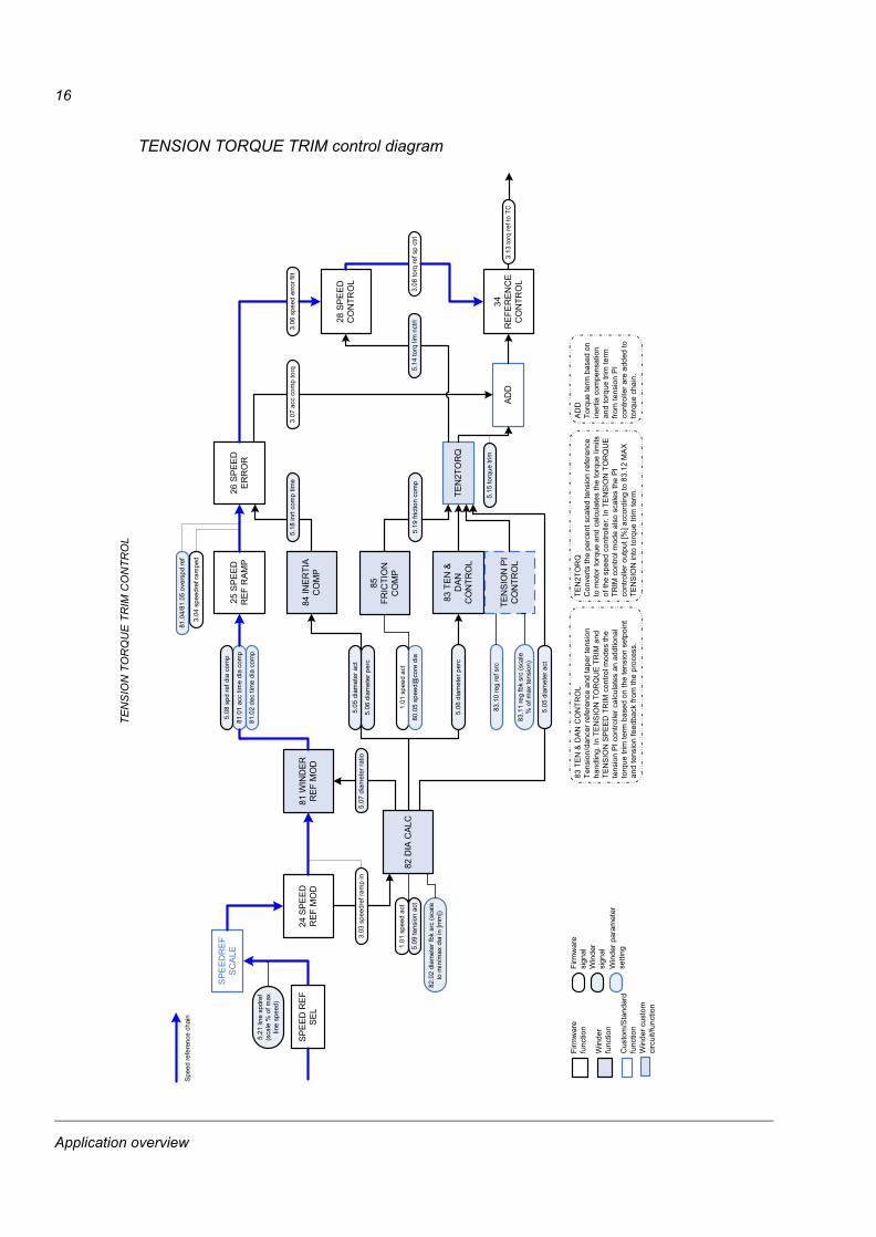
Load cell feedback is required. Tension of the web is controlled by calculating the torque reference of the motor, which is the product of the user-given tension reference and the actual roll radius. In addition, the tension control PID modifies the final motor torque reference based on the tension feedback from the load cell. Inertia and friction compensation can be used to improve the tension control accuracy.
The drive is running as speed controlled; the torque limits of the speed controller are controlled by the tension control. To ensure that the drive is always running against the calculated speed controller torque limits, the application adds an overspeed reference to the final speed reference. The amount of overspeed reference is adaptable with parameters. Accurate web material information is required.
The TENSION TORQUE TRIM tension control may result in a stable steady-state performance, but on the other hand it is less adaptable to a wide variety of web materials than the TENSION SPEED TRIM tension control. The TENSION TORQUE TRIM tension control is suitable especially for non-stretchy materials and when high dynamic accuracy is needed.
See TENSION TORQUE TRIM control diagram on page 16.
Application overview
16
TENSION TORQUE TRIM control diagram
���
����
��
����
�
���
���
���
���
�
����
���
���
��
���
�
���
����
��
(�)(
����
����
���"%
����
���
���
��
���
����
�
�����
��
*��
��
�
�
�(�*
���+
��
���
�
�*�
,��
���
��
��
�
�
���
����
*�
��
�
��
��)�
����
���"
!-
��).
���"
%�-
����"
-�$
��),
���"
%�-
����
��!
��),
���"
%�-
����
��!
��)�
���"
%�-
���"
!-
�)�)
����
���/
!$��
���"
����
����-�
!$%
��-�%
�
*��
��
���
���
�
*�
*��
*
�0
���
���
��
�
�*�
(��
��
���
���
���
�
*�
��
�(�
�(�-$
�1���
��-$�
*�
(�)�
�-$�1
������
��!-
����
���-$
�1���
%��
!-��
����
�-$�1
5��-�
�%
(�).
�"!!
�!$%
��-$
�1
���)
��"!
!�-�%
����
"�!$
%�
��)�
����
������
�"�!
$%�
���)
���
!�-�%
����
"�!$
%�
(�)�
����
����
���"%
���
��)�
����
���"
!-
��)2
�-���
�$��
"!-
���2
����!
-�$��
!$%
�
(�),
����
����
��$�
����-
�(��
)���
3���
����!
�(��
����
3��8
9���
!� �
!"��
�#
�$��%
"&�-�
���$
�'
���)
�6��
�)��
$7��
����
����
����
���
���
��
���
�����
����
����
�!"
���#
�$��%
"&�
�����
����
�'
��)
���
"%�-
����8
9���
!� �
!"��
�-$
�%��
6%"&
���"
����:%
%;'
���%
4"�
���5
�!-�$
�
���
����
�5�!
-�$�
���
����!
5�-$
%�
!��!
5�-6�
5�!-
�$�
�5�
-$%
6�-"
��"�
���5
�!-�$
�
���%
4"�
����
3�"�
���
����
��3�
"��
����
���"�
"%�-
���
��--�
�3
*��
*
�0
�$�
7��-�
�-<��
���!
��-��
!"��
��-�
���$
����
����
�!��
-$�%
$-$�
�-$�1
5��"
���!
"�!5
�"-�
��-<
��-$
�15�
���%
�-��
$��-<
����
����
!$�-
�$���
�����
�*�
��
� �
�*
�0
>�
�*�
���!
$�-�$
��%$�
��"�
�$��
!"��
��-<
����
�!$
�-�$
�����$
5-�5
-�:#
;�"!!
$���
�3�-$
��(�
���
�?
�*�
��
� �
���-$
�-$�1
5��-�
�%�-�
�%�
�(�*
��
�+��
����
�
*�
*�
���$
�6�"
�!��
�����
���!
��"�
��-"
����-
����
$��
<"��
���3�
����*
��
��
��*
�
0>
��*
���
�"��
�*�
��
� �
���
���
�*�
���!
$�-�$
��%$�
���-<
��-�
���$
���
��!$�
-�$���
��!"�
!5�"
-���
"��"
��-�$
�"��
-$�1
5��-�
�%�-�
�%�8
"���
�$��
-<��
-���
�$��
��-�
$��-
�"�
��-�
���$
����
��8"
!9���
$%�-<
����
$!��
��
��
�*$
�15�
�-��%
�8"�
���$
����
��-�"
�!$%
����
"-�$
��"�
��-$
�15�
�-��%
�-��%
���$
%�-�
���$
���
��!$
�-�$
�����"
���"
����
�-$�
-$�1
5��!
<"��
�
��������� ��������������
���
�����
����
�!��
!<"�
�
��)�
���"
%�-
���"
!-
Application overview

17
TENSION SPEED TRIM
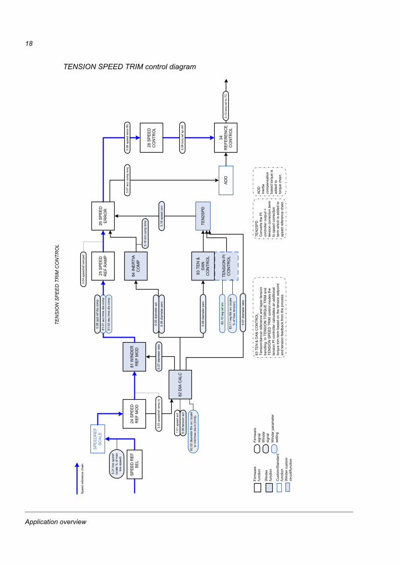
Load cell feedback is required. Tension of the web is controlled by calculating the torque reference of the motor, which is the product of the user-given tension reference and the actual roll radius. In addition, the tension control PID modifies the final motor speed reference based on the tension feedback from the load cell. Inertia compensation can be used to improve the tension control accuracy. The drive is running as speed controlled.
When running in the TENSION SPEED TRIM control mode, the tension controller is very adaptable to a large variety of web material characteristics. The TENSION SPEED TRIM tension control is suitable especially for stretchy materials demanding smooth control of the tension.
See TENSION SPEED TRIM control diagram on page 18.
Application overview
18
TENSION SPEED TRIM control diagram
���
����
��
����
�
���
���
���
���
�
����
���
���
��
���
�
���
����
��
(�)(
����
����
���"%
����
���
���
��
���
����
�
�����
��
*��
��
�
�
�(�*
���+
��
���
�
�*�
,��
���
��
��
�
�
��).
���"
%�-
����"
-�$
��),
���"
%�-
����
��!
��),
���"
%�-
����
��!
��)�
���"
%�-
���"
!-
����
����-�
!$%
��-�%
�
*��
��
���
���
�
*�
*��
���
���
���
��
�
�*�
(��
��
���
���
���
�
*�
��
�(�
�(�-$
�1���
��-$�
*�
(�)�
�-$�1
������
��!-
��
���,
����
���!
$��
(�).
�"!!
�!$%
��-$
�1
���)
��"!
!�-�%
����
"�!$
%�
��)�
����
������
�"�!
$%�
���)
���
!�-�%
����
"�!$
%�
(�)�
����
����
���"%
���
��)�
����
���"
!-
��)2
�-���
�$��
"!-
(�),
����
����
��$�
����-
�(��
)���
3���
����!
����
���
���
��
���
�����
����
����
�!"
���#
�$��%
"&�
�����
����
�'
��)
���
"%�-
����8
9���
!� �
!"��
�-$
�%��
6%"&
���"
����:%
%;'
�(��
����
3��8
9���
!� �
!"��
�#
�$��%
"&�-�
���$
�'
���%
4"�
���5
�!-�$
�
���
����
�5�!
-�$�
���
����!
5�-$
%�
!��!
5�-6�
5�!-
�$�
�5�
-$%
6�-"
��"�
���5
�!-�$
�
���%
4"�
����
3�"�
���
����
��3�
"��
����
���"�
"%�-
���
��--�
�3
*��
��
��
$�7�
�-��-<
���
��!$
�-�$
�����$
5-�5
-�@�
-���
�$��
!$��
�!-�$
��-�
�%�
-$��
����
�!$�
��!-
�$��
-��%
�4<�
!<���
�"��
���-$
���
����
����
���!
��!<
"���
�(�*
��
�+��
����
�
*�
*�
���$
�6�"
�!��
�����
���!
��"�
��-"
����-
����
$��
<"��
���3�
����*
��
��
��*
�
0>
��*
���
�"��
�*�
��
� �
���
���
�*�
���!
$�-�$
��%$�
���-<
��-�
���$
���
��!$�
-�$���
��!"�
!5�"
-���
"��"
��-�$
�"��
-$�1
5��-�
�%�-�
�%�8
"���
�$��
-<��
-���
�$��
��-�
$��-
�"�
��-�
���$
����
��8"
!9���
$%�-<
����
$!��
��
���
�����
����
�!��
!<"�
�
����������������������
��
���
��-�"
�!$
%��
��"-
�$��
8"��
��-$
�15�
����
"���
��-$
�-$
�15�
�!<"
���
��).
���"
%�-
����"
-�$
Application overview
19
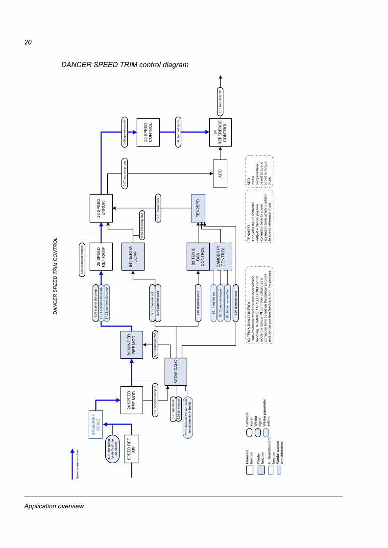
DANCER SPEED TRIM
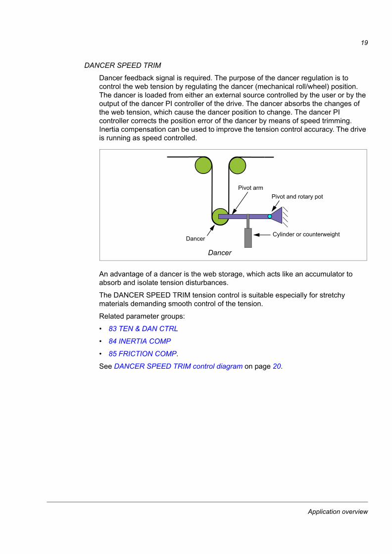
Dancer feedback signal is required. The purpose of the dancer regulation is to control the web tension by regulating the dancer (mechanical roll/wheel) position. The dancer is loaded from either an external source controlled by the user or by the output of the dancer PI controller of the drive. The dancer absorbs the changes of the web tension, which cause the dancer position to change. The dancer PI controller corrects the position error of the dancer by means of speed trimming. Inertia compensation can be used to improve the tension control accuracy. The drive is running as speed controlled.
An advantage of a dancer is the web storage, which acts like an accumulator to absorb and isolate tension disturbances.
The DANCER SPEED TRIM tension control is suitable especially for stretchy materials demanding smooth control of the tension.
Related parameter groups:
• 83 TEN & DAN CTRL
• 84 INERTIA COMP
• 85 FRICTION COMP.
See DANCER SPEED TRIM control diagram on page 20.
Dancer
Pivot armPivot and rotary pot
Cylinder or counterweightDancer
Application overview
20
DANCER SPEED TRIM control diagram
���
����
��
���
�
�
����
��
���
��
��
����
���
���
��
���
�
���
����
��
(�)(
����
����
���"%
����
���
���
��
��
���
��
�
�����
��
*���
�
��
�(�*
��
�+�
��
��
�
�*�
,��
���
��
���
�
��).
���"
%�-
����"
-�$
��),
���"
%�-
����
��!
��),
���"
%�-
����
��!
��)�
���"
%�-
���"
!-
����
����-�
!$%
��-�%
�
��
��
����
���
�
*�
*��
��
�
���
���
��
�
�*�
(��
���
��
���
��
�
�*�
��
�(�
�(�-$
�1���
��-$�
*�
���,
����
���!
$��
(�).
�"!!
�!$%
��-$
�1
���)
��"!
!�-�%
����
"�!$
%�
��)�
����
������
�"�!
$%�
���)
���
!�-�%
����
"�!$
%�
(�)�
����
����
���"%
���
��)�
����
���"
!-
��)2
�-���
�$��
"!-
(�),
����
����
��$�
����-
�(��
���"
��!�
�-��
$���
�-
�(��
����
3��8
9���
!
(�)�
�-$�1
������
��!-
��
���
����
���
��
���
�����
����
����
�!"
���#
�$��%
"&�
�����
����
�'
��)
���
"%�-
����8
9���
!� �
!"��
�-$
�%��
6%"&
���"
����:%
%;'
���%
4"�
���5
�!-�$
�
���
����
�5�!
-�$�
���
����!
5�-$
%�
!��!
5�-6�
5�!-
�$�
�5�
-$%
6�-"
��"�
���5
�!-�$
�
���%
4"�
����
3�"�
���
����
��3�
"��
����
���"�
"%�-
���
��--�
�3
*��
��
��
$�7�
�-��-<
���
��!$�
-�$���
��$5
-�5-
�@��
"�!�
���$�
�-�$�
�!$
���!
-�$��
-��%
�-$��
����
�!$
���!
-�$��
-��%
�4<�
!<���
�"��
���
-$��
����
�����
���!
��!<
"���
�(�*
��
�+��
��
��
�*�
*���
�$�6
�"�!
�����
����
�!��
"���
-"��
��-��
��$�
�<"
�����
3����
����
��
���
��
��
�*�
���!
$�-�$
��%
$���
-<��
�"�!
����
��!$�
-�$���
��!"�
!5�"
-���
"�!$
���!
-�$��
-��%
�8"�
���$
��-<
���"
�!��
���-
�$��
-�"�
���"
�!��
��$�
�-�$�
�����
8"!9
���$%
�-<��
��$!
����
��
���
��-�"
�!$
%��
��"-
�$��
8"��
��-$
�15�
����
"���
��-$
�-$�1
5��
!<"�
��
���
�����
����
�!��
!<"�
�
�����������������������
��).
���"
%�-
����"
-�$
�(��
(�%
"&��
"��-�
"7��
Application overview
21
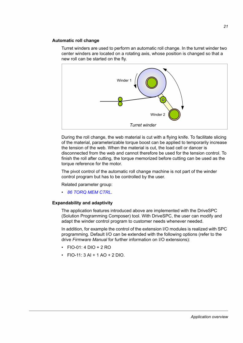
Automatic roll changeTurret winders are used to perform an automatic roll change. In the turret winder two center winders are located on a rotating axis, whose position is changed so that a new roll can be started on the fly.
During the roll change, the web material is cut with a flying knife. To facilitate slicing of the material, parameterizable torque boost can be applied to temporarily increase the tension of the web. When the material is cut, the load cell or dancer is disconnected from the web and cannot therefore be used for the tension control. To finish the roll after cutting, the torque memorized before cutting can be used as the torque reference for the motor.
The pivot control of the automatic roll change machine is not part of the winder control program but has to be controlled by the user.
Related parameter group:
• 86 TORQ MEM CTRL.
Expandability and adaptivityThe application features introduced above are implemented with the DriveSPC (Solution Programming Composer) tool. With DriveSPC, the user can modify and adapt the winder control program to customer needs whenever needed.
In addition, for example the control of the extension I/O modules is realized with SPC programming. Default I/O can be extended with the following options (refer to the drive Firmware Manual for further information on I/O extensions):
• FIO-01: 4 DIO + 2 RO
• FIO-11: 3 AI + 1 AO + 2 DIO.
Turret winder
Winder 1
Winder 2
Application overview

22
Application overview
23
Start-up
What this chapter containsThis chapter describes the basic commissioning procedure of the application.
How to commission the applicationIf an alarm or a fault is generated during the commissioning, see chapter Fault tracing (alarms and faults generated by the winder control program) or chapter Fault tracing in the drive Firmware Manual (other alarms and faults) for the possible causes and remedies.
DRIVE COMMISSIONING
Commission the drive according to the start-up instructions in the drive Firmware Manual. Ensure that the following parameters have appropriate values:
Firmware limits:• 20.01 MAXIMUM SPEED• 20.02 MINIMUM SPEED• 20.06 MAXIMUM TORQUE• 20.07 MINIMUM TORQUE
Firmware Manual
Firmware parameter groups for the drive control:• 10 DRIVE LOGIC (Start function and start/stop source)• 24 SPEED REF SEL
Firmware Manual
APPLICATION COMMISSIONING
Entering core data
Set the core diameter. 82.04 CORE DIAMETER
Reset the actual roll diameter to the core diameter. 82.09 DIA RESET ENA
Entering basic application control data
Set the winding mode. 80.01 WINDING MODE
Set the winding direction. 80.02 WINDING DIR
Set the process stop activation/deactivation. 80.03 PROCESS STOP
Set the maximum rotational speed in rpm for the winder at the core (= minimum diameter).
80.05 SPEED@CORE DIA
Start-up
24
Set the ratio of the motor rpm to the spindle rpm when the spindle rpm is scaled as 1. Example: Set parameter value to 2 if the motor rotates two rounds as the spindle rotates one round (2:1).
80.06 GEAR RATIO
Set the acceleration time from zero to the speed defined by parameter 25.02 SPEED SCALING (see the drive Firmware Manual).
81.01 ACC TIME
Set the deceleration time from the speed defined by parameter 25.02 SPEED SCALING to zero (see the drive Firmware Manual).
81.02 DEC TIME
Set the time within which the drive is stopped from the speed defined by parameter 25.02 SPEED SCALING if process stop is activated by parameter 80.03 PROCESS STOP.
81.03 PROCESS STP TIME
Entering inertia and friction compensation data
Check that the tension controller is disabled, ie, parameter 83.01 REG CTRL ENA = C.False.
83.01 REG CTRL ENA
Set the inertia and friction data using parameters in group 84 INERTIA COMP and 85 FRICTION COMP. For more information, see pages 40 and 42, respectively.
84 INERTIA COMP 84 INERTIA COMP,85 FRICTION COMP 85 FRICTION COMP
Verifying set data
Start the drive to rotate the spindle and core without the web to verify that the line speed matches the line speed reference. Confirm the setting of parameter 80.05 SPEED@CORE DIA if there is a mismatch between the line speed and the roll speed.
80.05 SPEED@CORE DIA
Check that the winding/unwinding directions are according to the winding mode and winding direction parameters.
80.01 WINDING MODE, 80.02 WINDING DIR
Rotate the core and spindle to verify the inertia and friction compensation data set above.
84 INERTIA COMP 84 INERTIA COMP,85 FRICTION COMP 85 FRICTION COMP
Entering winder data
For winder applications only. For infeeder applications, go directly to step Entering infeeder data on page 25.
Set the web and roll data using parameters in group 82 DIAMETER CALC.
82 DIAMETER CALC 82 DIAMETER CALC
Select the tension control mode. 83.02 TENSION CTRLMODE
Enable the tension control by setting 83.01 REG CTRL ENA to ENABLED.Go to step Winder and infeeder, continued on page 25.
83.01 REG CTRL ENA
Start-up
25
Entering infeeder data
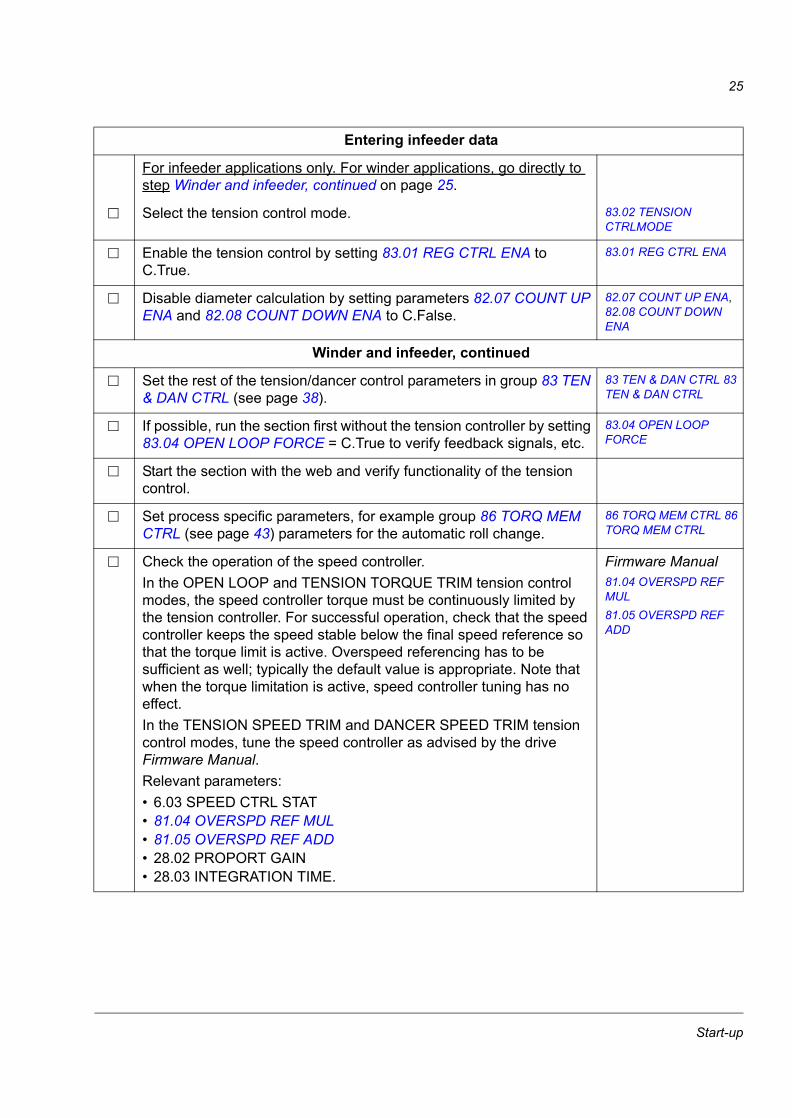
For infeeder applications only. For winder applications, go directly to step Winder and infeeder, continued on page 25.
Select the tension control mode. 83.02 TENSION CTRLMODE
Enable the tension control by setting 83.01 REG CTRL ENA to C.True.
83.01 REG CTRL ENA
Disable diameter calculation by setting parameters 82.07 COUNT UP ENA and 82.08 COUNT DOWN ENA to C.False.
82.07 COUNT UP ENA, 82.08 COUNT DOWN ENA
Winder and infeeder, continued
Set the rest of the tension/dancer control parameters in group 83 TEN & DAN CTRL (see page 38).
83 TEN & DAN CTRL 83 TEN & DAN CTRL
If possible, run the section first without the tension controller by setting 83.04 OPEN LOOP FORCE = C.True to verify feedback signals, etc.
83.04 OPEN LOOP FORCE
Start the section with the web and verify functionality of the tension control.
Set process specific parameters, for example group 86 TORQ MEM CTRL (see page 43) parameters for the automatic roll change.
86 TORQ MEM CTRL 86 TORQ MEM CTRL
Check the operation of the speed controller. In the OPEN LOOP and TENSION TORQUE TRIM tension control modes, the speed controller torque must be continuously limited by the tension controller. For successful operation, check that the speed controller keeps the speed stable below the final speed reference so that the torque limit is active. Overspeed referencing has to be sufficient as well; typically the default value is appropriate. Note that when the torque limitation is active, speed controller tuning has no effect.In the TENSION SPEED TRIM and DANCER SPEED TRIM tension control modes, tune the speed controller as advised by the drive Firmware Manual. Relevant parameters:• 6.03 SPEED CTRL STAT• 81.04 OVERSPD REF MUL• 81.05 OVERSPD REF ADD• 28.02 PROPORT GAIN• 28.03 INTEGRATION TIME.
Firmware Manual81.04 OVERSPD REF MUL81.05 OVERSPD REF ADD
Start-up

26
Start-up
27
Default control connections
What this chapter containsThis chapter shows the default control connections of the JCU Control Unit.
More information on the connectivity of the JCU is given in the Hardware Manual of the drive.
Default control connections
28
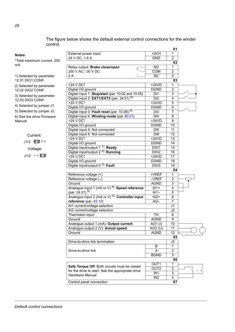
The figure below shows the default external control connections for the winder control.
Notes:*Total maximum current: 200 mA
1) Selected by parameter 12.01 DIO1 CONF.2) Selected by parameter 12.02 DIO2 CONF.3) Selected by parameter 12.03 DIO3 CONF.4) Selected by jumper J1.5) Selected by jumper J2.6) See the drive Firmware Manual.
X1External power input24 V DC, 1.6 A
+24VI 1GND 2
X2Relay output: Brake close/open250 V AC / 30 V DC2 A
NO 1COM 2NC 3
X3+24 V DC* +24VD 1Digital I/O ground DGND 2Digital input 1: Stop/start (par. 10.02 and 10.05) DI1 3Digital input 2: EXT1/EXT2 (par. 34.01) 6) DI2 4+24 V DC* +24VD 5Digital I/O ground DGND 6Digital input 3: Fault reset (par. 10.08) 6) DI3 7Digital input 4: Winding mode (par 80.01) DI4 8+24 V DC* +24VD 9Digital I/O ground DGND 10Digital input 5: Not connected DI5 11Digital input 6: Not connected DI6 12+24 V DC* +24VD 13Digital I/O ground DGND 14Digital input/output 1 1): Ready DIO1 15Digital input/output 2 2): Running DIO2 16+24 V DC* +24VD 17Digital I/O ground DGND 18Digital input/output 3 3): Fault DIO3 19
X4Reference voltage (+) +VREF 1Reference voltage (–) –VREF 2Ground AGND 3Analogue input 1 (mA or V) 4): Speed reference (par. 24.01) 6)
AI1+ 4AI1– 5
Analogue input 2 (mA or V) 5): Controller input reference (par. 83.10)
AI2+ 6AI2– 7
AI1 current/voltage selection J1AI2 current/voltage selection J2Thermistor input TH 8Ground AGND 9Analogue output 1 (mA): Output current AO1 (I) 10Analogue output 2 (V): Actual speed AO2 (U) 11Ground AGND 12
X5Drive-to-drive link termination J3
Drive-to-drive linkB 1A 2
BGND 3X6
Safe Torque Off. Both circuits must be closed for the drive to start. See the appropriate drive Hardware Manual.
OUT1 1OUT2 2IN1 3IN2 4
Control panel connection X7
Current:
Voltage:
J1/2
J1/2
Default control connections
29
Actual signals and parameters
What this chapter containsThe chapter describes the actual signals and parameters related to the winder control program. For other actual signals and parameters, refer to the drive Firmware Manual.
The range and default value, when applicable, as well as a page number for more detailed information are given for each signal and parameter. The page number refers to the related technology function block or custom circuit in chapter Technology function blocks and custom circuits.
Note: The total range of winder-related actual signals in group 5 is -32768…32768. The range which the application uses is mentioned in this manual.
Terms and abbreviationsThe table defines the terms and abbreviations used in the parameter and actual signal tables.
Term DefinitionActual signal Signal measured or calculated by the drive. Can be monitored by the user.
No user setting possible.
Parameter A user-adjustable operation instruction of the drive.
Val./Def. On a parameter row: Parameter default value.On rows under the parameter row: Parameter alternative values (for parameters with value names).
Page Page in chapter Technology function blocks and custom circuits where the signal or parameter is listed as an input or output to a technology function block or custom circuit. More information on the signal or parameter, for example type, unit and fieldbus equivalent are shown there.
C.False, C.True When adjusting a bit pointer parameter on the control panel, value 0 (FALSE) is displayed as “C.FALSE” and value 1 (TRUE) as “C.TRUE”. See also Bit ptr on page 50.
P.xx.yy A value pointer points to the value of another parameter/signal. The source parameter is given in format P.xx.yy, where xx = parameter group, yy = parameter index. See also Val ptr on page 50.
Actual signals and parameters
30
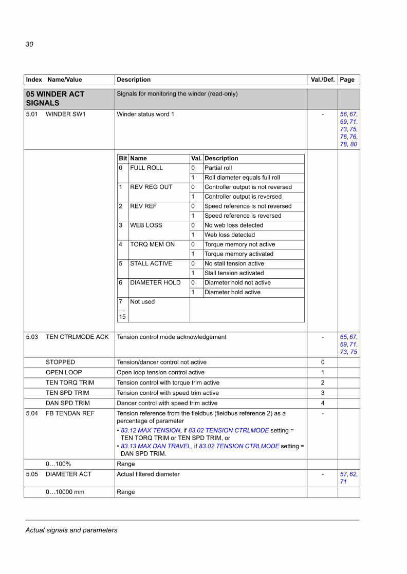
Index Name/Value Description Val./Def. Page
0505 WINDER ACT SIGNALS
Signals for monitoring the winder (read-only)
5.01 WINDER SW1 Winder status word 1 - 56, 67, 69, 71, 73, 75, 76, 76, 78, 80
5.03 TEN CTRLMODE ACK Tension control mode acknowledgement - 65, 67, 69, 71, 73, 75
STOPPED Tension/dancer control not active 0
OPEN LOOP Open loop tension control active 1
TEN TORQ TRIM Tension control with torque trim active 2
TEN SPD TRIM Tension control with speed trim active 3
DAN SPD TRIM Dancer control with speed trim active 4
5.04 FB TENDAN REF Tension reference from the fieldbus (fieldbus reference 2) as a percentage of parameter• 83.12 MAX TENSION, if 83.02 TENSION CTRLMODE setting =
TEN TORQ TRIM or TEN SPD TRIM, or • 83.13 MAX DAN TRAVEL, if 83.02 TENSION CTRLMODE setting =
DAN SPD TRIM.
-
0…100% Range
5.05 DIAMETER ACT Actual filtered diameter - 57, 62, 71
0…10000 mm Range
Bit Name Val. Description0 FULL ROLL 0 Partial roll
1 Roll diameter equals full roll1 REV REG OUT 0 Controller output is not reversed
1 Controller output is reversed2 REV REF 0 Speed reference is not reversed
1 Speed reference is reversed3 WEB LOSS 0 No web loss detected
1 Web loss detected4 TORQ MEM ON 0 Torque memory not active
1 Torque memory activated5 STALL ACTIVE 0 No stall tension active
1 Stall tension activated6 DIAMETER HOLD 0 Diameter hold not active
1 Diameter hold active7…15
Not used
Actual signals and parameters
31
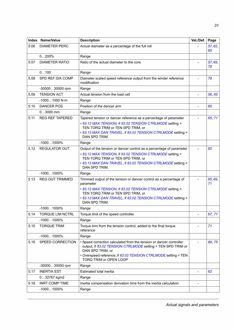
5.06 DIAMETER PERC Actual diameter as a percentage of the full roll - 57, 62, 65
0…200% Range
5.07 DIAMETER RATIO Ratio of the actual diameter to the core - 57, 69, 78
0…100 Range
5.08 SPD REF DIA COMP Diameter scaled speed reference output from the winder reference modification
- 78
-30000…30000 rpm Range
5.09 TENSION ACT Actual tension from the load cell - 56, 65
-1000…1000 N·m Range
5.10 DANCER POS Position of the dancer arm - 65
0…3000 mm Range
5.11 REG REF TAPERED Tapered tension or dancer reference as a percentage of parameter• 83.12 MAX TENSION, if 83.02 TENSION CTRLMODE setting =
TEN TORQ TRIM or TEN SPD TRIM, or • 83.13 MAX DAN TRAVEL, if 83.02 TENSION CTRLMODE setting =
DAN SPD TRIM.
- 65, 71
-1000…1000% Range
5.12 REGULATOR OUT Output of the tension or dancer control as a percentage of parameter• 83.12 MAX TENSION, if 83.02 TENSION CTRLMODE setting =
TEN TORQ TRIM or TEN SPD TRIM, or • 83.13 MAX DAN TRAVEL, if 83.02 TENSION CTRLMODE setting =
DAN SPD TRIM.
- 65
-1000…1000% Range
5.13 REG OUT TRIMMED Trimmed output of the tension or dancer control as a percentage of parameter• 83.12 MAX TENSION, if 83.02 TENSION CTRLMODE setting =
TEN TORQ TRIM or TEN SPD TRIM, or • 83.13 MAX DAN TRAVEL, if 83.02 TENSION CTRLMODE setting =
DAN SPD TRIM.
- 65, 69, 71
-1000…1000% Range
5.14 TORQUE LIM NCTRL Torque limit of the speed controller - 67, 71
-1000…1000% Range
5.15 TORQUE TRIM Torque trim from the tension control, added to the final torque reference
- 71
-1000…1000% Range
5.16 SPEED CORRECTION • Speed correction calculated from the tension or dancer controller output, if 83.02 TENSION CTRLMODE setting = TEN SPD TRIM or DAN SPD TRIM, or
• Overspeed reference, if 83.02 TENSION CTRLMODE setting = TEN TORQ TRIM or OPEN LOOP
- 69, 75
-30000…30000 rpm Range
5.17 INERTIA EST Estimated total inertia - 62
0…32767 kgm2 Range
5.18 INRT COMP TIME Inertia compensation derivation time from the inertia calculation -
-1000…1000% Range
Index Name/Value Description Val./Def. Page
Actual signals and parameters
32
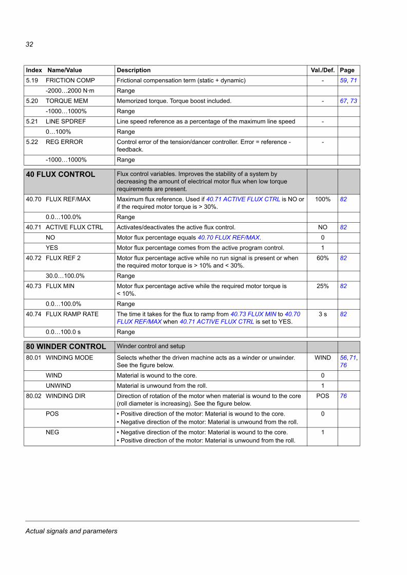
5.19 FRICTION COMP Frictional compensation term (static + dynamic) - 59, 71
-2000…2000 N·m Range
5.20 TORQUE MEM Memorized torque. Torque boost included. - 67, 73
-1000…1000% Range
5.21 LINE SPDREF Line speed reference as a percentage of the maximum line speed -
0…100% Range
5.22 REG ERROR Control error of the tension/dancer controller. Error = reference - feedback.
-
-1000…1000% Range
4040 FLUX CONTROL Flux control variables. Improves the stability of a system by decreasing the amount of electrical motor flux when low torque requirements are present.
40.70 FLUX REF/MAX Maximum flux reference. Used if 40.71 ACTIVE FLUX CTRL is NO or if the required motor torque is > 30%.
100% 82
0.0…100.0% Range
40.71 ACTIVE FLUX CTRL Activates/deactivates the active flux control. NO 82
NO Motor flux percentage equals 40.70 FLUX REF/MAX. 0
YES Motor flux percentage comes from the active program control. 1
40.72 FLUX REF 2 Motor flux percentage active while no run signal is present or when the required motor torque is > 10% and < 30%.
60% 82
30.0…100.0% Range
40.73 FLUX MIN Motor flux percentage active while the required motor torque is < 10%.
25% 82
0.0…100.0% Range
40.74 FLUX RAMP RATE The time it takes for the flux to ramp from 40.73 FLUX MIN to 40.70 FLUX REF/MAX when 40.71 ACTIVE FLUX CTRL is set to YES.
3 s 82
0.0…100.0 s Range
8080 WINDER CONTROL Winder control and setup
80.01 WINDING MODE Selects whether the driven machine acts as a winder or unwinder. See the figure below.
WIND 56, 71, 76
WIND Material is wound to the core. 0
UNWIND Material is unwound from the roll. 1
80.02 WINDING DIR Direction of rotation of the motor when material is wound to the core (roll diameter is increasing). See the figure below.
POS 76
POS • Positive direction of the motor: Material is wound to the core.• Negative direction of the motor: Material is unwound from the roll.
0
NEG • Negative direction of the motor: Material is wound to the core.• Positive direction of the motor: Material is unwound from the roll.
1
Index Name/Value Description Val./Def. Page
Actual signals and parameters
33
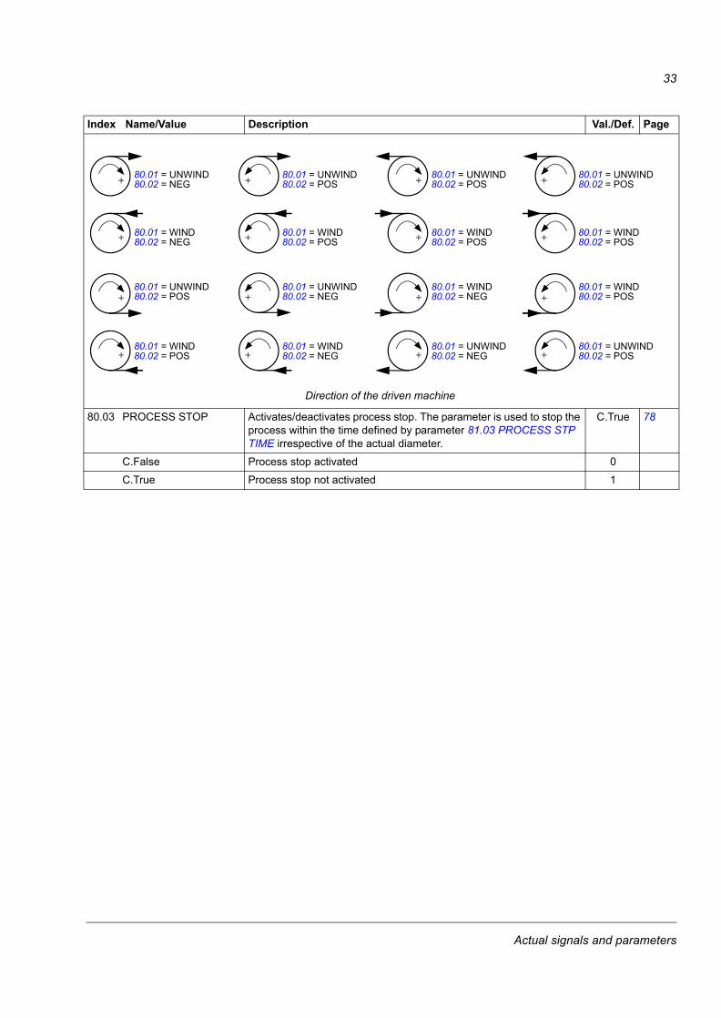
80.03 PROCESS STOP Activates/deactivates process stop. The parameter is used to stop the process within the time defined by parameter 81.03 PROCESS STP TIME irrespective of the actual diameter.
C.True 78
C.False Process stop activated 0
C.True Process stop not activated 1
Index Name/Value Description Val./Def. Page
Direction of the driven machine
80.01 = UNWIND80.02 = NEG
80.01 = WIND80.02 = NEG
80.01 = UNWIND80.02 = POS
80.01 = WIND80.02 = POS
80.01 = UNWIND80.02 = POS
80.01 = WIND80.02 = POS
80.01 = UNWIND80.02 = NEG
80.01 = WIND80.02 = NEG
80.01 = UNWIND80.02 = POS
80.01 = WIND80.02 = POS
80.01 = WIND80.02 = NEG
80.01 = UNWIND80.02 = NEG
80.01 = UNWIND80.02 = POS
80.01 = WIND80.02 = POS
80.01 = WIND80.02 = POS
80.01 = UNWIND80.02 = POS
Actual signals and parameters
34
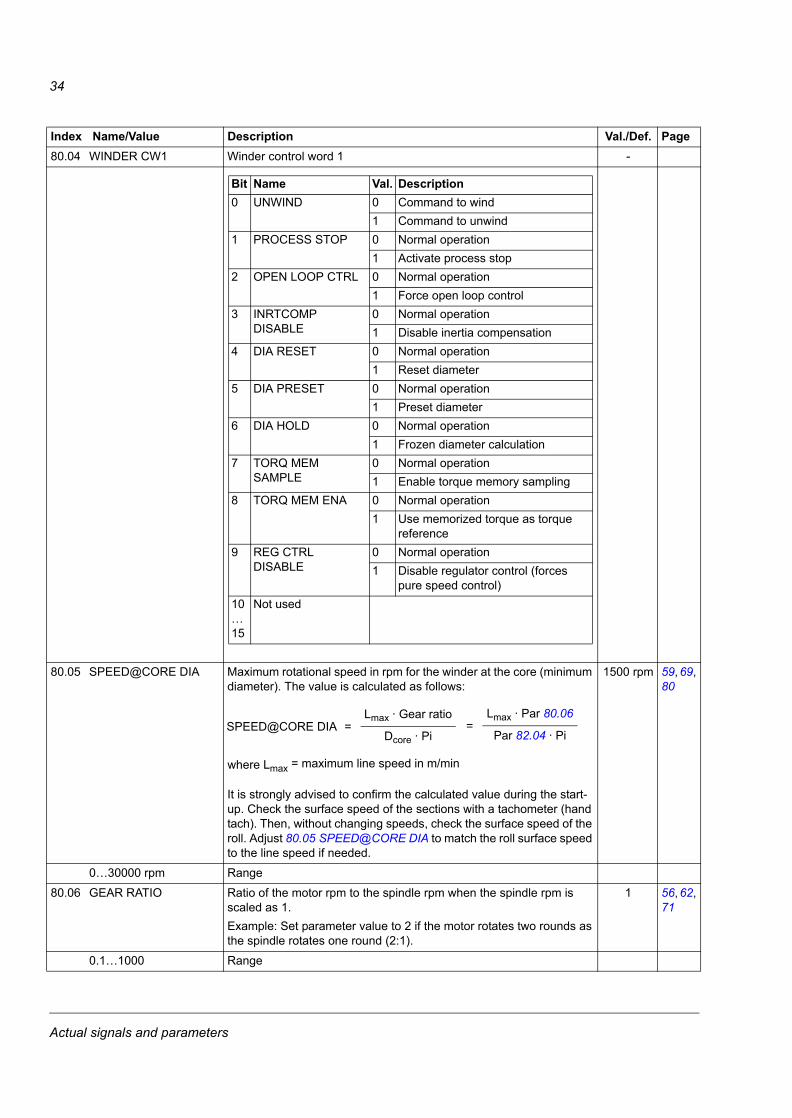
80.04 WINDER CW1 Winder control word 1 -
80.05 SPEED@CORE DIA Maximum rotational speed in rpm for the winder at the core (minimum diameter). The value is calculated as follows:
It is strongly advised to confirm the calculated value during the start-up. Check the surface speed of the sections with a tachometer (hand tach). Then, without changing speeds, check the surface speed of the roll. Adjust 80.05 SPEED@CORE DIA to match the roll surface speed to the line speed if needed.
1500 rpm 59, 69, 80
0…30000 rpm Range
80.06 GEAR RATIO Ratio of the motor rpm to the spindle rpm when the spindle rpm is scaled as 1. Example: Set parameter value to 2 if the motor rotates two rounds as the spindle rotates one round (2:1).
1 56, 62, 71
0.1…1000 Range
Index Name/Value Description Val./Def. Page
Bit Name Val. Description0 UNWIND 0 Command to wind
1 Command to unwind1 PROCESS STOP 0 Normal operation
1 Activate process stop2 OPEN LOOP CTRL 0 Normal operation
1 Force open loop control3 INRTCOMP
DISABLE0 Normal operation1 Disable inertia compensation
4 DIA RESET 0 Normal operation1 Reset diameter
5 DIA PRESET 0 Normal operation1 Preset diameter
6 DIA HOLD 0 Normal operation1 Frozen diameter calculation
7 TORQ MEM SAMPLE
0 Normal operation1 Enable torque memory sampling
8 TORQ MEM ENA 0 Normal operation1 Use memorized torque as torque
reference9 REG CTRL
DISABLE0 Normal operation1 Disable regulator control (forces
pure speed control)10…15
Not used
SPEED@CORE DIA Lmax · Gear ratio
Dcore · Pi=
Lmax · Par 80.06
Par 82.04 · Pi=
where Lmax = maximum line speed in m/min
Actual signals and parameters
35
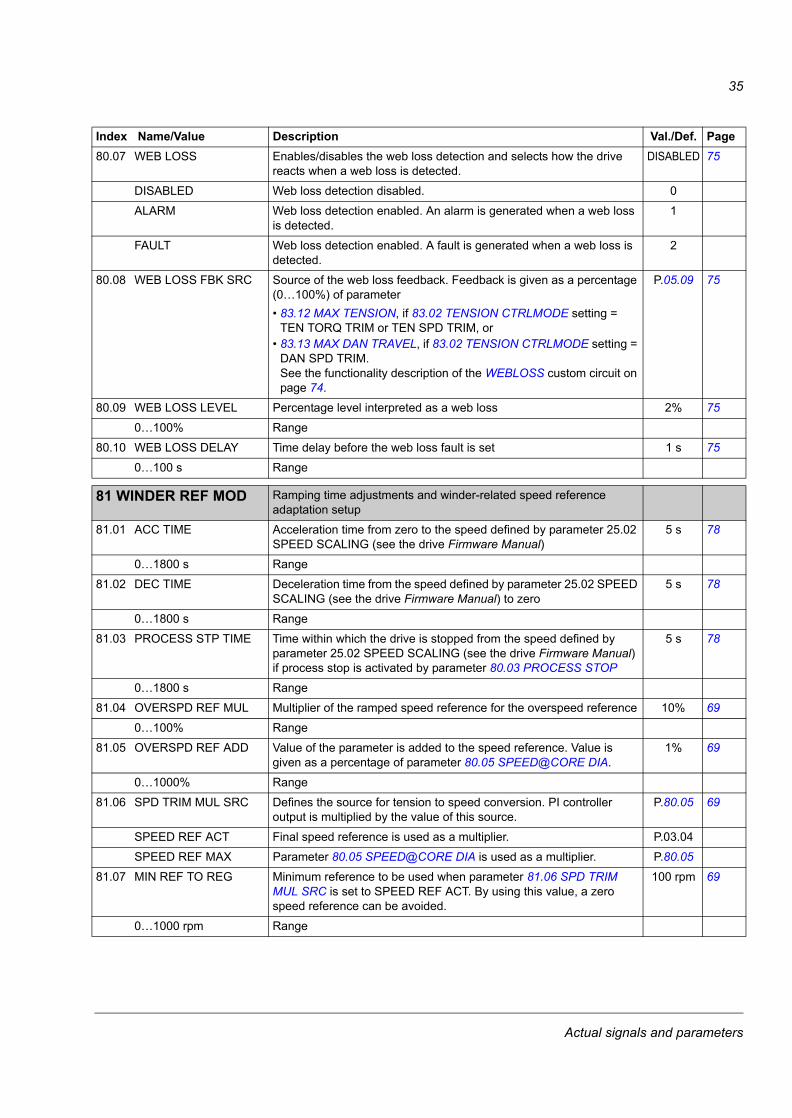
80.07 WEB LOSS Enables/disables the web loss detection and selects how the drive reacts when a web loss is detected.
DISABLED 75
DISABLED Web loss detection disabled. 0
ALARM Web loss detection enabled. An alarm is generated when a web loss is detected.
1
FAULT Web loss detection enabled. A fault is generated when a web loss is detected.
2
80.08 WEB LOSS FBK SRC Source of the web loss feedback. Feedback is given as a percentage (0…100%) of parameter• 83.12 MAX TENSION, if 83.02 TENSION CTRLMODE setting =
TEN TORQ TRIM or TEN SPD TRIM, or • 83.13 MAX DAN TRAVEL, if 83.02 TENSION CTRLMODE setting =
DAN SPD TRIM. See the functionality description of the WEBLOSS custom circuit on page 74.
P.05.09 75
80.09 WEB LOSS LEVEL Percentage level interpreted as a web loss 2% 75
0…100% Range
80.10 WEB LOSS DELAY Time delay before the web loss fault is set 1 s 75
0…100 s Range
8081 WINDER REF MOD Ramping time adjustments and winder-related speed reference adaptation setup
81.01 ACC TIME Acceleration time from zero to the speed defined by parameter 25.02 SPEED SCALING (see the drive Firmware Manual)
5 s 78
0…1800 s Range
81.02 DEC TIME Deceleration time from the speed defined by parameter 25.02 SPEED SCALING (see the drive Firmware Manual) to zero
5 s 78
0…1800 s Range
81.03 PROCESS STP TIME Time within which the drive is stopped from the speed defined by parameter 25.02 SPEED SCALING (see the drive Firmware Manual) if process stop is activated by parameter 80.03 PROCESS STOP
5 s 78
0…1800 s Range
81.04 OVERSPD REF MUL Multiplier of the ramped speed reference for the overspeed reference 10% 69
0…100% Range
81.05 OVERSPD REF ADD Value of the parameter is added to the speed reference. Value is given as a percentage of parameter 80.05 SPEED@CORE DIA.
1% 69
0…1000% Range
81.06 SPD TRIM MUL SRC Defines the source for tension to speed conversion. PI controller output is multiplied by the value of this source.
P.80.05 69
SPEED REF ACT Final speed reference is used as a multiplier. P.03.04
SPEED REF MAX Parameter 80.05 SPEED@CORE DIA is used as a multiplier. P.80.05
81.07 MIN REF TO REG Minimum reference to be used when parameter 81.06 SPD TRIM MUL SRC is set to SPEED REF ACT. By using this value, a zero speed reference can be avoided.
100 rpm 69
0…1000 rpm Range
Index Name/Value Description Val./Def. Page
Actual signals and parameters
36
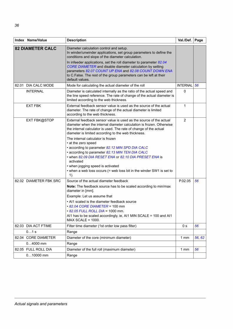
8282 DIAMETER CALC Diameter calculation control and setup.In winder/unwinder applications, set group parameters to define the conditions and slope of the diameter calculation.In infeeder applications, set the roll diameter to parameter 82.04 CORE DIAMETER and disable diameter calculation by setting parameters 82.07 COUNT UP ENA and 82.08 COUNT DOWN ENA to C.False. The rest of the group parameters can be left at their default values.
82.01 DIA CALC MODE Mode for calculating the actual diameter of the roll INTERNAL 56
INTERNAL Diameter is calculated internally as the ratio of the actual speed and the line speed reference. The rate of change of the actual diameter is limited according to the web thickness.
0
EXT FBK External feedback sensor value is used as the source of the actual diameter. The rate of change of the actual diameter is limited according to the web thickness.
1
EXT FBK@STOP External feedback sensor value is used as the source of the actual diameter when the internal diameter calculation is frozen. Otherwise the internal calculator is used. The rate of change of the actual diameter is limited according to the web thickness.The internal calculator is frozen• at the zero speed• according to parameter 82.12 MIN SPD DIA CALC• according to parameter 82.13 MIN TEN DIA CALC• when 82.09 DIA RESET ENA or 82.10 DIA PRESET ENA is
activated• when jogging speed is activated• when a web loss occurs (= web loss bit in the winder SW1 is set to
1).
2
82.02 DIAMETER FBK SRC Source of the actual diameter feedbackNote: The feedback source has to be scaled according to min/max diameter in [mm].Example: Let us assume that • AI1 scaled is the diameter feedback source• 82.04 CORE DIAMETER = 100 mm• 82.05 FULL ROLL DIA = 1000 mm. AI1 has to be scaled accordingly, ie, AI1 MIN SCALE = 100 and AI1 MAX SCALE = 1000.
P.02.05 56
82.03 DIA ACT FTIME Filter time diameter (1st order low pass filter) 0 s 56
0…1 s Range
82.04 CORE DIAMETER Diameter of the core (minimum diameter) 1 mm 56, 62
0…4000 mm Range
82.05 FULL ROLL DIA Diameter of the full roll (maximum diameter) 1 mm 56
0…10000 mm Range
Index Name/Value Description Val./Def. Page
Actual signals and parameters
37
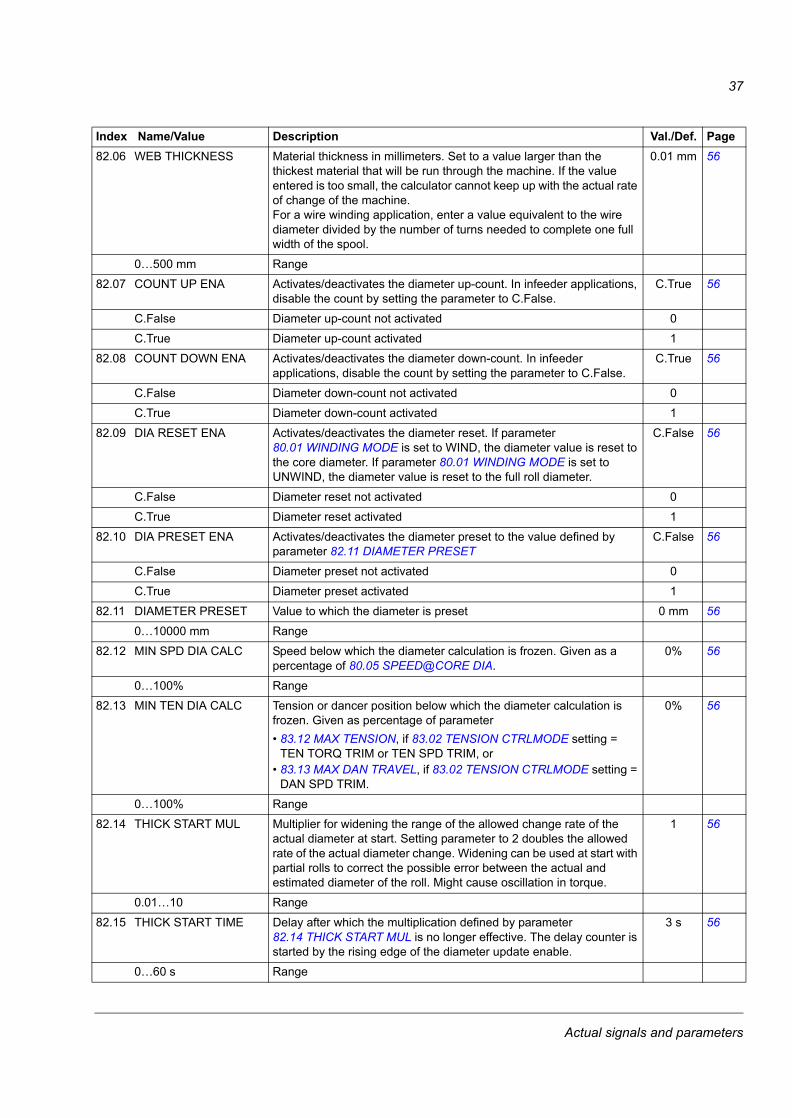
82.06 WEB THICKNESS Material thickness in millimeters. Set to a value larger than the thickest material that will be run through the machine. If the value entered is too small, the calculator cannot keep up with the actual rate of change of the machine. For a wire winding application, enter a value equivalent to the wire diameter divided by the number of turns needed to complete one full width of the spool.
0.01 mm 56
0…500 mm Range
82.07 COUNT UP ENA Activates/deactivates the diameter up-count. In infeeder applications, disable the count by setting the parameter to C.False.
C.True 56
C.False Diameter up-count not activated 0
C.True Diameter up-count activated 1
82.08 COUNT DOWN ENA Activates/deactivates the diameter down-count. In infeeder applications, disable the count by setting the parameter to C.False.
C.True 56
C.False Diameter down-count not activated 0
C.True Diameter down-count activated 1
82.09 DIA RESET ENA Activates/deactivates the diameter reset. If parameter 80.01 WINDING MODE is set to WIND, the diameter value is reset to the core diameter. If parameter 80.01 WINDING MODE is set to UNWIND, the diameter value is reset to the full roll diameter.
C.False 56
C.False Diameter reset not activated 0
C.True Diameter reset activated 1
82.10 DIA PRESET ENA Activates/deactivates the diameter preset to the value defined by parameter 82.11 DIAMETER PRESET
C.False 56
C.False Diameter preset not activated 0
C.True Diameter preset activated 1
82.11 DIAMETER PRESET Value to which the diameter is preset 0 mm 56
0…10000 mm Range
82.12 MIN SPD DIA CALC Speed below which the diameter calculation is frozen. Given as a percentage of 80.05 SPEED@CORE DIA.
0% 56
0…100% Range
82.13 MIN TEN DIA CALC Tension or dancer position below which the diameter calculation is frozen. Given as percentage of parameter• 83.12 MAX TENSION, if 83.02 TENSION CTRLMODE setting =
TEN TORQ TRIM or TEN SPD TRIM, or • 83.13 MAX DAN TRAVEL, if 83.02 TENSION CTRLMODE setting =
DAN SPD TRIM.
0% 56
0…100% Range
82.14 THICK START MUL Multiplier for widening the range of the allowed change rate of the actual diameter at start. Setting parameter to 2 doubles the allowed rate of the actual diameter change. Widening can be used at start with partial rolls to correct the possible error between the actual and estimated diameter of the roll. Might cause oscillation in torque.
1 56
0.01…10 Range
82.15 THICK START TIME Delay after which the multiplication defined by parameter 82.14 THICK START MUL is no longer effective. The delay counter is started by the rising edge of the diameter update enable.
3 s 56
0…60 s Range
Index Name/Value Description Val./Def. Page
Actual signals and parameters
38
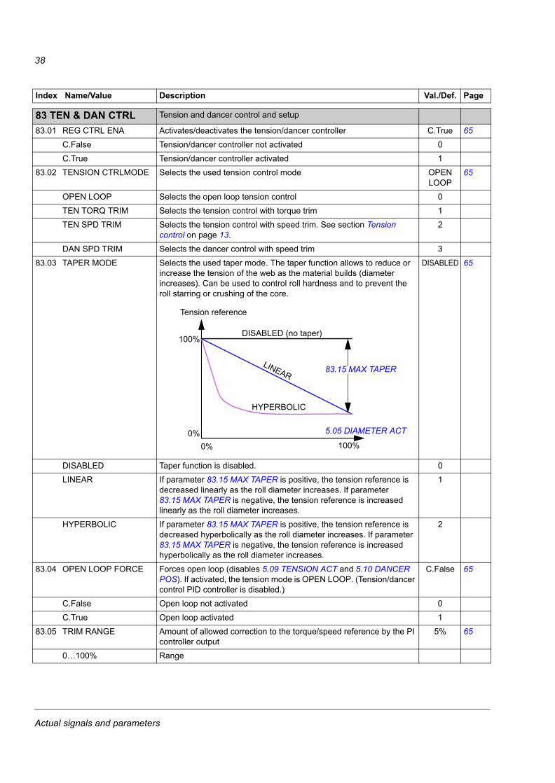
8383 TEN & DAN CTRL Tension and dancer control and setup
83.01 REG CTRL ENA Activates/deactivates the tension/dancer controller C.True 65
C.False Tension/dancer controller not activated 0
C.True Tension/dancer controller activated 1
83.02 TENSION CTRLMODE Selects the used tension control mode OPEN LOOP
65
OPEN LOOP Selects the open loop tension control 0
TEN TORQ TRIM Selects the tension control with torque trim 1
TEN SPD TRIM Selects the tension control with speed trim. See section Tension control on page 13.
2
DAN SPD TRIM Selects the dancer control with speed trim 3
83.03 TAPER MODE Selects the used taper mode. The taper function allows to reduce or increase the tension of the web as the material builds (diameter increases). Can be used to control roll hardness and to prevent the roll starring or crushing of the core.
DISABLED 65
DISABLED Taper function is disabled. 0
LINEAR If parameter 83.15 MAX TAPER is positive, the tension reference is decreased linearly as the roll diameter increases. If parameter 83.15 MAX TAPER is negative, the tension reference is increased linearly as the roll diameter increases.
1
HYPERBOLIC If parameter 83.15 MAX TAPER is positive, the tension reference is decreased hyperbolically as the roll diameter increases. If parameter 83.15 MAX TAPER is negative, the tension reference is increased hyperbolically as the roll diameter increases.
2
83.04 OPEN LOOP FORCE Forces open loop (disables 5.09 TENSION ACT and 5.10 DANCER POS). If activated, the tension mode is OPEN LOOP. (Tension/dancer control PID controller is disabled.)
C.False 65
C.False Open loop not activated 0
C.True Open loop activated 1
83.05 TRIM RANGE Amount of allowed correction to the torque/speed reference by the PI controller output
5% 65
0…100% Range
Index Name/Value Description Val./Def. Page
DISABLED (no taper)
LINEAR
HYPERBOLIC
100%
100%
0%0%
Tension reference
5.05 DIAMETER ACT
83.15 MAX TAPER
Actual signals and parameters
39
83.06 STALL ENA Activates/deactivates the stall function C.False 80
C.False Stall function not activated 0
C.True Stall function activated 1
83.07 CORE GAIN Tension controller gain used for the core (minimum diameter) 10 65, 80
0…1000 Range
83.08 FULL ROLL GAIN Tension controller gain used for the full roll 10 65, 80
0…1000 Range
83.09 INTEGRATION TIME Integration time of the tension control 1 s 65, 80
0…100 s Range
83.10 REG REF SRC Source of the controller input reference (%). In the dancer control (83.02 TENSION CTRLMODE setting = DAN SPD TRIM), the parameter is in use only if the drive is used for controlling the dancer loading.In the tension control modes, the parameter selects the source of the tension reference.
P.02.07 65, 80
83.11 REG FBK SRC Source of the controller feedback (%)In the TENSION TORQUE TRIM and TENSION SPEED TRIM tension control modes, the controller feedback source is scaled according to the value of parameter 83.12 MAX TENSION. 100% corresponds to the set maximum tension value (N). In the DANCER SPEED TRIM tension control mode, the scaling is done according to the value of parameter 83.13 MAX DAN TRAVEL. 100% corresponds to the set maximum dancer travel (mm).
P.02.07 65
83.12 MAX TENSION Scales the reference given as a percentage (83.10 REG REF SRC) to N
10 N 65, 71
0…30000 N Range
83.13 MAX DAN TRAVEL Scales the reference given as a percentage (83.10 REG REF SRC) to mm. The parameter is used only if parameter 83.02 TENSION CTRLMODE setting = DAN SPD TRIM.
1000 mm 65
0…3000 mm Range
Index Name/Value Description Val./Def. Page
Actual signals and parameters
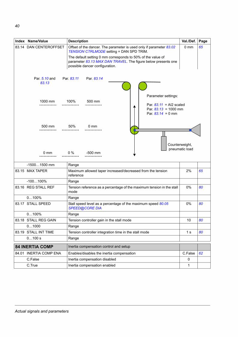
40
83.14 DAN CENTEROFFSET Offset of the dancer. The parameter is used only if parameter 83.02 TENSION CTRLMODE setting = DAN SPD TRIM. The default setting 0 mm corresponds to 50% of the value of parameter 83.13 MAX DAN TRAVEL. The figure below presents one possible dancer configuration.
0 mm 65
-1500…1500 mm Range
83.15 MAX TAPER Maximum allowed taper increased/decreased from the tension reference
2% 65
-100…100% Range
83.16 REG STALL REF Tension reference as a percentage of the maximum tension in the stall mode
0% 80
0…100% Range
83.17 STALL SPEED Stall speed level as a percentage of the maximum speed 80.05 SPEED@CORE DIA
0% 80
0…100% Range
83.18 STALL REG GAIN Tension controller gain in the stall mode 10 80
0…1000 Range
83.19 STALL INT TIME Tension controller integration time in the stall mode 1 s 80
0…100 s Range
8484 INERTIA COMP Inertia compensation control and setup
84.01 INERTIA COMP ENA Enables/disables the inertia compensation C.False 62
C.False Inertia compensation disabled 0
C.True Inertia compensation enabled 1
Index Name/Value Description Val./Def. Page
500 mm100 %1000 mm
0 mm 0 % -500 mm
5.10DANCER POS
83.13MAX DAN TRAVEL
83.11REF FBK SRC
500 mm 50 % 0 mm
83.14DAN CENTEROFFSET
PARAMETER SETTINGS:
83.11 REG FBK SRC = AI2 scaled83.13 MAX DAN TRAVEL = 1000 mm83.14 DAN CENTEROFFSET = 0 mm
COUNTERWEIGHT, PNEUMATIC LOAD
Par. 83.14 Par. 83.11 Par. 5.10 and83.13
Parameter settings:
Par. 83.11 = AI2 scaledPar. 83.13 = 1000 mmPar. 83.14 = 0 mm
Counterweight, pneumatic load
1000 mm 100% 500 mm
500 mm 50% 0 mm
0 mm 0 % -500 mm
Actual signals and parameters
41
84.02 ROLL WEIGHT SEL Selects whether the calculated or user given roll weight is used for the inertia calculation
CALCULATED
62
CALCULATED Roll weight is calculated using parameters 84.05 WEB DENSITY and 84.06 WEB WIDTH.
0
PAR 84.04 Value of parameter 84.04 FULL ROLL WEIGHT is used as the roll weight.
1
84.03 FIXED INERTIA Fixed inertia, includes the inertia of the motor, shaft and gearing. Inertia of the shaft and gearbox must be reflected on the motor side.
0 kgm2 62
0…30000 kgm2 Range
84.04 FULL ROLL WEIGHT Weight of the full roll 0 kg 62
0…30000 kg Range
84.05 WEB DENSITY Density of the web material. The parameter is not used if parameter 84.02 ROLL WEIGHT SEL = PAR 84.04. The table below gives examples of the densities for some materials. In a wire winding application, density values smaller than the actual density of the material can be used since the material is not necessarily wound evenly to the spool and the inertia will therefore be smaller.
0 kg/m3 62
10…15000 kg/m3 Range
84.06 WEB WIDTH Width of the web material. The parameter is not used if parameter 84.02 ROLL WEIGHT SEL = PAR 84.04.
0 mm 62
0…10000 mm Range
Index Name/Value Description Val./Def. Page
Fixed inertiaGear inertia + Shaft inertia
Gear ratio 2= Motor inertia +
Material Density (kg/m3)Steel 7800Aluminium 2700Copper 8960Paper 700…1200Rubber (soft) 900…1100Nylon 1100Wool 1300
Actual signals and parameters
42
8585 FRICTION COMP Friction compensation control and setup. Static friction is the static mechanical friction of the section. Dynamic (linear) friction is an additional friction loss component as a function of the roll speed. Proper friction compensation is essential especially in the open loop tension control to improve accuracy of the tension control. For proper adjustment of the friction compensation, you can use the following procedure:1. Place an empty core into the section.2. Deactivate the tension control by setting 83.01 REG CTRL ENA =
C.False.3. Deactivate the inertia compensation by setting 84.01 INERTIA
COMP ENA = C.False. Check that all parameter values in group 85 FRICTION COMP 85 FRICTION COMP are set to zero.
4. Change to local control (eg, from the panel) and set the speed reference to 10% of the maximum (0.1 · 80.05 SPEED@CORE DIA). Start the drive.
5. Multiply the average of 1.06 TORQUE by 99.12 MOT NOM TORQUE and enter the product to 85.01 STATIC FRICTION.
6. Increase the speed to 20% of 80.05 SPEED@CORE DIA.7. Multiply the average of 1.06 TORQUE by 99.12 MOT NOM
TORQUE and subtract 85.01 STATIC FRICTION from the result. Multiply the product by 0.8 and enter the product to 85.02 DYN FRICTION@20.
8. Increase the speed to 40% of 80.05 SPEED@CORE DIA.9. Multiply the average of 1.06 TORQUE by 99.12 MOT NOM
TORQUE and subtract 85.01 STATIC FRICTION from the result. Multiply the product by 0.8 and enter the product to 85.03 DYN FRICTION@40.
10. Increase the speed to 60% of 80.05 SPEED@CORE DIA.11. Multiply the average of 1.06 TORQUE by 99.12 MOT NOM
TORQUE and subtract 85.01 STATIC FRICTION from the result. Multiply the product by 0.8 and enter the product to 85.04 DYN FRICTION@60.
12. Increase the speed to 80% of 80.05 SPEED@CORE DIA.13. Multiply the average of 1.06 TORQUE by 99.12 MOT NOM
TORQUE and subtract 85.01 STATIC FRICTION from the result. Multiply the product by 0.8 and enter the product to 85.05 DYN FRICTION@80.
14. Increase the speed to 80.05 SPEED@CORE DIA.15. Multiply the average of 1.06 TORQUE by 99.12 MOT NOM
TORQUE and subtract 85.01 STATIC FRICTION from the result. Multiply the product by 0.8 and enter the product to 85.06 DYN FRICTION@100.
85.01 STATIC FRICTION Mechanical friction of the section 0 N·m 59
-1000…1000 N·m Range
85.02 DYN FRICTION@20 Dynamic friction component at 20% of the maximum speed 80.05 SPEED@CORE DIA
0 N·m 59
-1000…1000 N·m Range
85.03 DYN FRICTION@40 Dynamic friction component at 40% of the maximum speed 80.05 SPEED@CORE DIA
0 N·m 59
-1000…1000 N·m Range
Index Name/Value Description Val./Def. Page
Actual signals and parameters
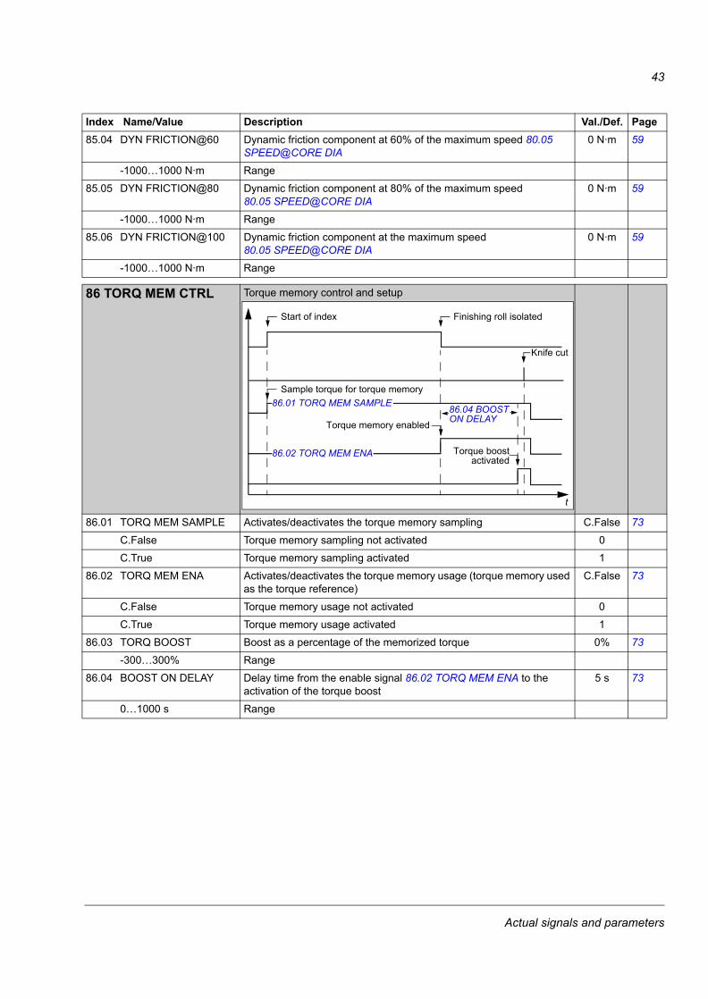
43
85.04 DYN FRICTION@60 Dynamic friction component at 60% of the maximum speed 80.05 SPEED@CORE DIA
0 N·m 59
-1000…1000 N·m Range
85.05 DYN FRICTION@80 Dynamic friction component at 80% of the maximum speed 80.05 SPEED@CORE DIA
0 N·m 59
-1000…1000 N·m Range
85.06 DYN FRICTION@100 Dynamic friction component at the maximum speed 80.05 SPEED@CORE DIA
0 N·m 59
-1000…1000 N·m Range
8686 TORQ MEM CTRL Torque memory control and setup
86.01 TORQ MEM SAMPLE Activates/deactivates the torque memory sampling C.False 73
C.False Torque memory sampling not activated 0
C.True Torque memory sampling activated 1
86.02 TORQ MEM ENA Activates/deactivates the torque memory usage (torque memory used as the torque reference)
C.False 73
C.False Torque memory usage not activated 0
C.True Torque memory usage activated 1
86.03 TORQ BOOST Boost as a percentage of the memorized torque 0% 73
-300…300% Range
86.04 BOOST ON DELAY Delay time from the enable signal 86.02 TORQ MEM ENA to the activation of the torque boost
5 s 73
0…1000 s Range
Index Name/Value Description Val./Def. Page
Start of index
Sample torque for torque memory
Finishing roll isolated
Knife cut
t
86.04 BOOST ON DELAY
86.01 TORQ MEM SAMPLE
86.02 TORQ MEM ENA
Torque memory enabled
Torque boostactivated
Actual signals and parameters

44
Actual signals and parameters
45
Fieldbus control
What this chapter containsThis chapter describes how the winder control program communicates with the external devices through the serial communication interfaces.
Supported fieldbus profilesThe winder control program supports fieldbus profiles (parameter 51.05 PROFILE) PROFIdrive and ABB Drives Profile. Transparent 16, transparent 32 and PROFIdrive motion profiles are not supported for referencing. To set up the bus configuration, refer to the corresponding fieldbus adapter manual (includes also the contents of the main status and control words).
FBA reference 1 / FBA actual signal 1FBA reference 1 (parameter 2.14 FBA MAIN REF1) is always considered as the line speed reference. 16-bit references must be used. The line speed reference is always handled as an absolute value. Whenever needed, the direction (wind/unwind) can be changed with parameter 80.01 WINDING MODE or with bit 0 of parameter 80.04 WINDER CW1.
FBA actual signal 1 is always considered as the actual line speed. 16-bit actual values must be used. The direction is indicated by the sign of the value.
PROFIdrive scaling0…0x4000 (0…16384) corresponds to 0…100% of the maximum line speed (parameter 80.05 SPEED@CORE DIA) in the reference and actual values.
ABB Drives scaling0…0x4E20 (0…20000) corresponds to 0…100% of the maximum line speed (parameter 80.05 SPEED@CORE DIA) in the reference and actual values.
FBA reference 2 / FBA actual signal 2FBA reference 2 (parameter 2.15 FBA MAIN REF2) is always considered as the tension reference or dancer load setpoint, depending on the selected tension control mode (parameter 83.02 TENSION CTRLMODE). 16-bit references must be used.
FBA actual signal 2 is always considered as the actual tension or dancer position, depending on the selected tension control mode. Actual tension is not available in the OPEN LOOP tension control mode. 16-bit actual values must be used.
Fieldbus control
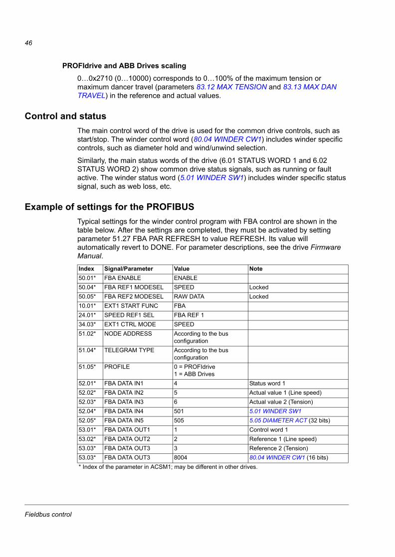
46
PROFIdrive and ABB Drives scaling0…0x2710 (0…10000) corresponds to 0…100% of the maximum tension or maximum dancer travel (parameters 83.12 MAX TENSION and 83.13 MAX DAN TRAVEL) in the reference and actual values.
Control and statusThe main control word of the drive is used for the common drive controls, such as start/stop. The winder control word (80.04 WINDER CW1) includes winder specific controls, such as diameter hold and wind/unwind selection.
Similarly, the main status words of the drive (6.01 STATUS WORD 1 and 6.02 STATUS WORD 2) show common drive status signals, such as running or fault active. The winder status word (5.01 WINDER SW1) includes winder specific status signal, such as web loss, etc.
Example of settings for the PROFIBUSTypical settings for the winder control program with FBA control are shown in the table below. After the settings are completed, they must be activated by setting parameter 51.27 FBA PAR REFRESH to value REFRESH. Its value will automatically revert to DONE. For parameter descriptions, see the drive Firmware Manual.
Index Signal/Parameter Value Note50.01* FBA ENABLE ENABLE50.04* FBA REF1 MODESEL SPEED Locked50.05* FBA REF2 MODESEL RAW DATA Locked10.01* EXT1 START FUNC FBA24.01* SPEED REF1 SEL FBA REF 134.03* EXT1 CTRL MODE SPEED51.02* NODE ADDRESS According to the bus
configuration51.04* TELEGRAM TYPE According to the bus
configuration51.05* PROFILE 0 = PROFIdrive
1 = ABB Drives 52.01* FBA DATA IN1 4 Status word 152.02* FBA DATA IN2 5 Actual value 1 (Line speed)52.03* FBA DATA IN3 6 Actual value 2 (Tension)52.04* FBA DATA IN4 501 5.01 WINDER SW152.05* FBA DATA IN5 505 5.05 DIAMETER ACT (32 bits)53.01* FBA DATA OUT1 1 Control word 153.02* FBA DATA OUT2 2 Reference 1 (Line speed)53.03* FBA DATA OUT3 3 Reference 2 (Tension)53.03* FBA DATA OUT3 8004 80.04 WINDER CW1 (16 bits)* Index of the parameter in ACSM1; may be different in other drives.
Fieldbus control
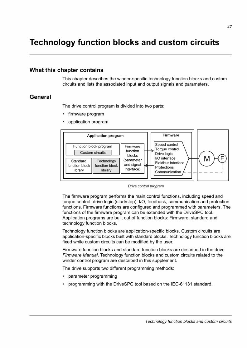
47
Technology function blocks and custom circuits
What this chapter containsThis chapter describes the winder-specific technology function blocks and custom circuits and lists the associated input and output signals and parameters.
GeneralThe drive control program is divided into two parts:
• firmware program
• application program.
The firmware program performs the main control functions, including speed and torque control, drive logic (start/stop), I/O, feedback, communication and protection functions. Firmware functions are configured and programmed with parameters. The functions of the firmware program can be extended with the DriveSPC tool. Application programs are built out of function blocks: Firmware, standard and technology function blocks.
Technology function blocks are application-specific blocks. Custom circuits are application-specific blocks built with standard blocks. Technology function blocks are fixed while custom circuits can be modified by the user.
Firmware function blocks and standard function blocks are described in the drive Firmware Manual. Technology function blocks and custom circuits related to the winder control program are described in this supplement.
The drive supports two different programming methods:
• parameter programming
• programming with the DriveSPC tool based on the IEC-61131 standard.
M
Application program Firmware
E
Speed control Torque controlDrive logicI/O interfaceFieldbus interfaceProtectionsCommunication
Standard function block
library
Function block program
Drive control program
Technology function block
library
Firmware function blocks
(parameter and signal interface)
Custom circuits
Technology function blocks and custom circuits
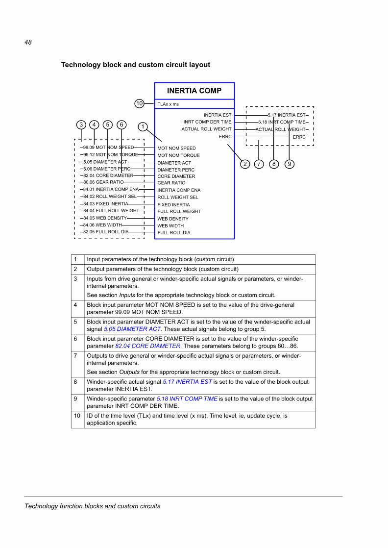
48
Technology block and custom circuit layout
INERTIA COMP
5.18 INRT COMP TIME
TLAx x ms
INRT COMP DER TIMEACTUAL ROLL WEIGHT
INERTIA EST 5.17 INERTIA EST
ACTUAL ROLL WEIGHT
MOT NOM SPEED99.09 MOT NOM SPEED
CORE DIAMETER82.04 CORE DIAMETER
99.12 MOT NOM TORQUE5.05 DIAMETER ACT
MOT NOM TORQUE
DIAMETER ACT
GEAR RATIO80.06 GEAR RATIO
INERTIA COMP ENA84.01 INERTIA COMP ENA
FULL ROLL WEIGHT84.04 FULL ROLL WEIGHT
84.02 ROLL WEIGHT SEL84.03 FIXED INERTIA
ROLL WEIGHT SEL
FIXED INERTIA
WEB DENSITY84.05 WEB DENSITY
WEB WIDTH84.06 WEB WIDTH
5.06 DIAMETER PERC DIAMETER PERC
FULL ROLL DIA82.05 FULL ROLL DIA
ERRC ERRC
1 Input parameters of the technology block (custom circuit)
2 Output parameters of the technology block (custom circuit)
3 Inputs from drive general or winder-specific actual signals or parameters, or winder-internal parameters.See section Inputs for the appropriate technology block or custom circuit.
4 Block input parameter MOT NOM SPEED is set to the value of the drive-general parameter 99.09 MOT NOM SPEED.
5 Block input parameter DIAMETER ACT is set to the value of the winder-specific actual signal 5.05 DIAMETER ACT. These actual signals belong to group 5.
6 Block input parameter CORE DIAMETER is set to the value of the winder-specific parameter 82.04 CORE DIAMETER. These parameters belong to groups 80…86.
7 Outputs to drive general or winder-specific actual signals or parameters, or winder- internal parameters.See section Outputs for the appropriate technology block or custom circuit.
8 Winder-specific actual signal 5.17 INERTIA EST is set to the value of the block output parameter INERTIA EST.
9 Winder-specific parameter 5.18 INRT COMP TIME is set to the value of the block output parameter INRT COMP DER TIME.
10 ID of the time level (TLx) and time level (x ms). Time level, ie, update cycle, is application specific.
3 1
10
8
4 5
97
6
2
Technology function blocks and custom circuits

49
Actual signalsActual signals are signals measured or calculated by the drive. They are normally used for monitoring and diagnostics, and cannot be adjusted by the user. Winder-specific actual signals are in group 5.
For additional signal data, eg, description, see chapter Actual signals and parameters.
ParametersParameters are user-adjustable operation instructions of the drive. Winder-specific parameters are in groups 40 and 80…86.
For additional parameter data, eg, description and possible value selection list, see chapter Actual signals and parameters.
Technology function blocks and custom circuits
50
Terms in the parameter/signal tables
Term Definition
Actual signal Signal measured or calculated by the drive. Can be monitored by the user. No user setting is possible.
Data len. Length of data for fieldbus. May be different from the actual data length in the drive software.
Def Default value
Enum Enumerated list, ie, selection list
FbEq Fieldbus equivalent: The scaling between the value shown on the panel and the integer used in serial communication
INT32 32-bit integer value (31 bits + sign)
Bit ptr Bit pointer. A bit pointer parameter points to the value of a bit in another signal, or can be fixed to 0 (FALSE) or 1 (TRUE). In addition, bit pointer parameters may have a set of pre-selected choices.When adjusting a bit pointer parameter on the optional control panel, CONST is selected in order to fix the value to 0 (displayed as “C.FALSE”) or 1 (“C.TRUE”). POINTER is selected to define a source from another signal.A pointer value is given in format P.xx.yy.zz, where xx = parameter group, yy = parameter index, zz = bit number.Example: Digital input DI5 status, 2.01 DI STATUS bit 4, is used for diameter resetting by setting parameter 82.09 DIA RESET ENA to value P.02.01.04.
Val ptr Value pointer. A value pointer points to the value of another parameter/signal. The source parameter is given in format P.xx.yy, where xx = parameter group, yy = parameter index. In addition, value pointer parameters may have a set of pre-selected choices.Example: Tension signal, 5.09 TENSION ACT, is connected to analogue output AO1 by setting parameter 15.01 AO1 PTR to value P.05.09.
P. Page in chapter Actual signals and parameters where the description and possible value selection list for the signal or parameter are shown
Parameter A user-adjustable operation instruction of the drive
Pb Packed boolean
PT Parameter protection type. See WP and WPD.
REAL
REAL24
Signal See Actual signal.
Type Data type. See Enum, INT32, Bit ptr, Val ptr, Pb, REAL, REAL24, UINT32.
UINT32 32-bit unsigned integer value
WP Write protected parameter (ie, read only)
WPD Write protected parameter while the drive is running
16-bit value 16-bit value (31 bits + sign)
= integer value = fractional value
8-bit value 24-bit value (31 bits + sign)
= integer value = fractional value
Technology function blocks and custom circuits
51
Fieldbus equivalentSerial communication data between a fieldbus adapter and drive is transferred in integer format. Thus, the drive actual and reference signal values must be scaled to 16/32-bit integer values. Fieldbus equivalent defines the scaling between the signal value and the integer used in serial communication.
All the read and sent values are limited to 16/32 bits.
Example: If 82.04 CORE DIAMETER is set from an external control system, an integer value of 100 corresponds to 1 mm.
Fieldbus addressesFor FPBA-01 Profibus Adapter, FDNA-01 DeviceNet Adapter and FCAN-01 CANopen Adapter, see the User’s Manual of the fieldbus adapter module.
Pointer parameter format in fieldbus communicationValue and bit pointer parameters are transferred between the fieldbus adapter and drive as 32-bit integer values.
32-bit integer value pointersWhen a value pointer parameter is connected to the value of another parameter or signal, the format is as follows:
When a value pointer parameter is connected to an application program, the format is as follows:
Note: Value pointer parameters connected to an application program cannot be set through the fieldbus (ie, read access only).
Bit
30…31 16…29 8…15 0…7
Name Source type Not in use Group Index
Value 1 - 1…255 1…255
Description Value pointer is connected to
parameter/signal.
- Group of source parameter
Index of source parameter
Bit
30…31 24…29 0…23
Name Source type Not in use Address
Value 2 - 0…223
Description Value pointer is connected to application
program.
- Relative address of application program
variable
Technology function blocks and custom circuits
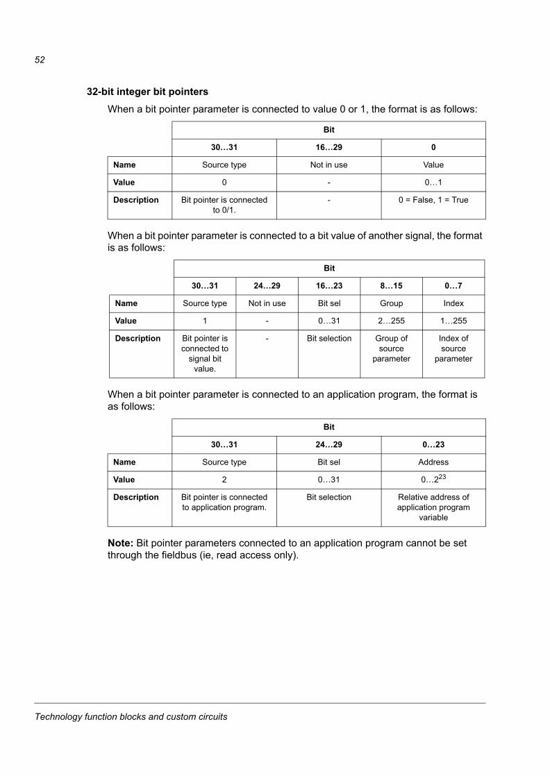
52
32-bit integer bit pointersWhen a bit pointer parameter is connected to value 0 or 1, the format is as follows:
When a bit pointer parameter is connected to a bit value of another signal, the format is as follows:
When a bit pointer parameter is connected to an application program, the format is as follows:
Note: Bit pointer parameters connected to an application program cannot be set through the fieldbus (ie, read access only).
Bit
30…31 16…29 0
Name Source type Not in use Value
Value 0 - 0…1
Description Bit pointer is connected to 0/1.
- 0 = False, 1 = True
Bit
30…31 24…29 16…23 8…15 0…7
Name Source type Not in use Bit sel Group Index
Value 1 - 0…31 2…255 1…255
Description Bit pointer is connected to
signal bit value.
- Bit selection Group of source
parameter
Index of source
parameter
Bit
30…31 24…29 0…23
Name Source type Bit sel Address
Value 2 0…31 0…223
Description Bit pointer is connected to application program.
Bit selection Relative address of application program
variable
Technology function blocks and custom circuits
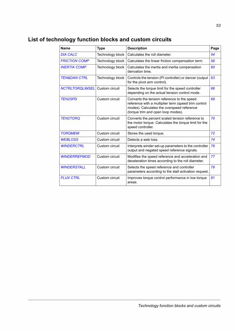
53
List of technology function blocks and custom circuitsName Type Description Page
DIA CALC Technology block Calculates the roll diameter. 54
FRICTION COMP Technology block Calculates the linear friction compensation term. 58
INERTIA COMP Technology block Calculates the inertia and inertia compensation derivation time.
60
TEN&DAN CTRL Technology block Controls the tension (PI controller) or dancer (output for the pivot arm control).
63
NCTRLTORQLIMSEL Custom circuit Selects the torque limit for the speed controller depending on the actual tension control mode.
66
TEN2SPD Custom circuit Converts the tension reference to the speed reference with a multiplier term (speed trim control modes). Calculates the overspeed reference (torque trim and open loop modes).
68
TEN2TORQ Custom circuit Converts the percent scaled tension reference to the motor torque. Calculates the torque limit for the speed controller.
70
TORQMEM Custom circuit Stores the used torque. 72
WEBLOSS Custom circuit Detects a web loss. 74
WINDERCTRL Custom circuit Interprets winder set-up parameters to the controller output and negated speed reference signals.
76
WINDERREFMOD Custom circuit Modifies the speed reference and acceleration and deceleration times according to the roll diameter.
77
WINDERSTALL Custom circuit Selects the speed reference and controller parameters according to the stall activation request.
79
FLUX CTRL Custom circuit Improves torque control performance in low torque areas.
81
Technology function blocks and custom circuits
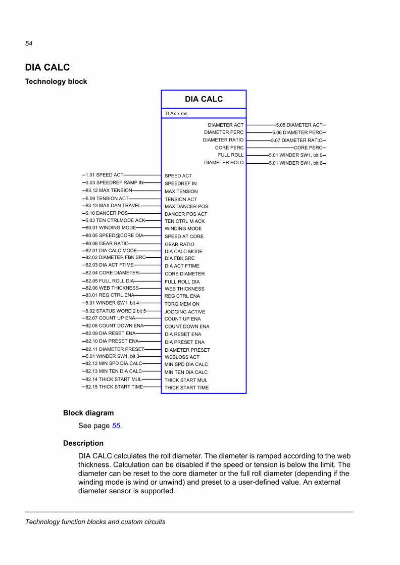
54
DIA CALCTechnology block
Block diagramSee page 55.
DescriptionDIA CALC calculates the roll diameter. The diameter is ramped according to the web thickness. Calculation can be disabled if the speed or tension is below the limit. The diameter can be reset to the core diameter or the full roll diameter (depending if the winding mode is wind or unwind) and preset to a user-defined value. An external diameter sensor is supported.
DIA CALC
5.06 DIAMETER PERC
TLAx x ms
DIAMETER PERCDIAMETER RATIO
DIAMETER ACT 5.05 DIAMETER ACT
5.07 DIAMETER RATIO
SPEED ACT1.01 SPEED ACT
TENSION ACT5.09 TENSION ACT
3.03 SPEEDREF RAMP IN83.12 MAX TENSION
SPEEDREF INMAX TENSION
MAX DANCER POS83.13 MAX DAN TRAVEL
5.01 WINDER SW1, bit 0FULL ROLLDIAMETER HOLD
CORE PERC CORE PERC
5.01 WINDER SW1, bit 6
DANCER POS ACT5.10 DANCER POS
GEAR RATIO80.06 GEAR RATIO
80.01 WINDING MODE80.05 SPEED@CORE DIA
WINDING MODESPEED AT CORE
DIA CALC MODE82.01 DIA CALC MODEDIA FBK SRC82.02 DIAMETER FBK SRC
FULL ROLL DIA82.05 FULL ROLL DIA
82.03 DIA ACT FTIME82.04 CORE DIAMETER
DIA ACT FTIMECORE DIAMETER
WEB THICKNESS82.06 WEB THICKNESS
JOGGING ACTIVE6.02 STATUS WORD 2 bit 5
83.01 REG CTRL ENA5.01 WINDER SW1, bit 4
REG CTRL ENATORQ MEM ON
COUNT UP ENA82.07 COUNT UP ENA
COUNT DOWN ENA82.08 COUNT DOWN ENA
DIAMETER PRESET82.11 DIAMETER PRESET
82.09 DIA RESET ENA82.10 DIA PRESET ENA
DIA RESET ENADIA PRESET ENA
WEBLOSS ACT5.01 WINDER SW1, bit 3
THICK START MUL82.14 THICK START MUL
82.12 MIN SPD DIA CALC82.13 MIN TEN DIA CALC
MIN SPD DIA CALCMIN TEN DIA CALC
THICK START TIME82.15 THICK START TIME
TEN CTRL M ACK5.03 TEN CTRLMODE ACK
Technology function blocks and custom circuits
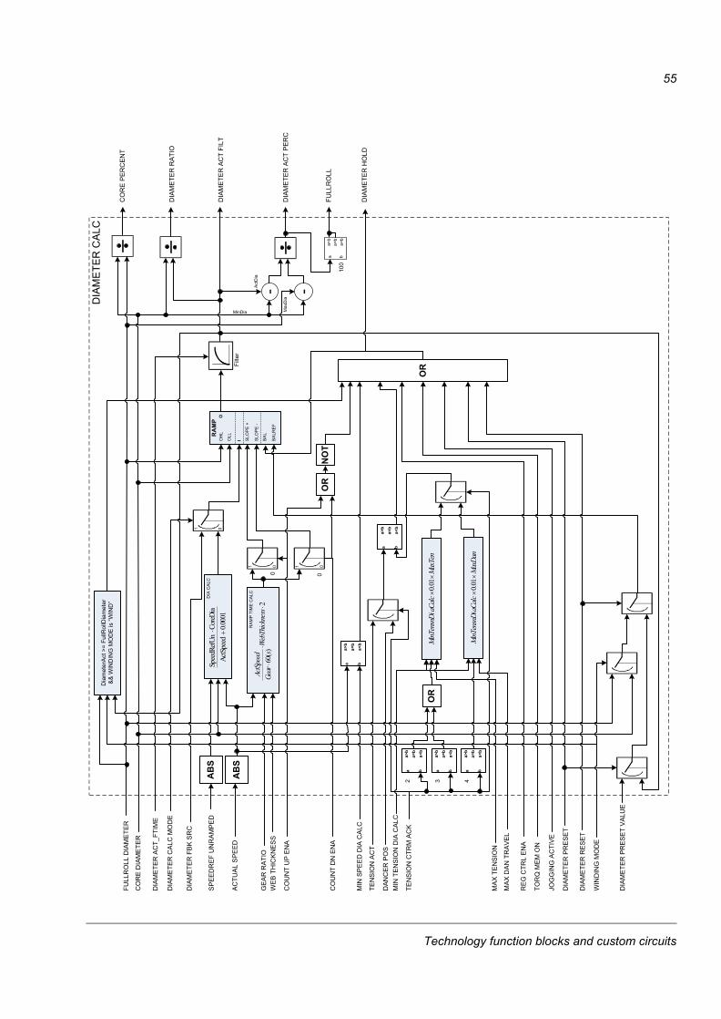
55
I SLO
PE
+
SLO
PE
-
BA
L
BA
LRE
F
OH
L
OLLR
AM
P
0 0
a b
a>b
a=b
a<b
O
OR
a b
a>b
a=b
a<b
a b
a>b
a=b
a<b
100
AB
S
AB
S
DIA
CA
LC
RA
MP
TIM
E C
ALC
FULL
RO
LL D
IAM
ETE
R
DIA
ME
TER
AC
T_FT
IME
DIA
ME
TER
CA
LC M
OD
E
AC
TUA
L S
PE
ED
SP
EE
DR
EF
UN
RA
MP
ED
DIA
ME
TER
FB
K S
RC
CO
RE
DIA
ME
TER
WE
B T
HIC
KN
ES
SG
EAR
RAT
IO
CO
UN
T U
P E
NA
CO
UN
T D
N E
NA
MIN
SP
EE
D D
IA C
ALC
WIN
DIN
G M
OD
E
MIN
TE
NS
ION
DIA
CA
LC
TEN
SIO
N A
CT
DIA
ME
TER
RE
SE
T
DIA
ME
TER
PR
ES
ET
DIA
ME
TER
PR
ES
ET
VA
LUE
DIA
ME
TER
CA
LC
CO
RE
PE
RC
EN
T
DIA
ME
TER
RA
TIO
DIA
ME
TER
AC
T FI
LT
DIA
ME
TER
AC
T P
ER
C
FULL
RO
LL
Act
Dia
MinDia Max
Dia
2)(
60�
��
ssWebThickne
sGearActSpeed
0.0001
ActSpeed
CoreDia
SpeedRefUn ��
1 0 1 0
1 0
Filte
r
RE
G C
TRL
EN
A
TOR
Q M
EM
ON
JOG
GIN
G A
CTI
VE
a b
a>b
a=b
a<b
a b
a>b
a=b
a<b
a b
a>b
a=b
a<b
TEN
SIO
N C
TRM
AC
K2 3 4
OR
MA
X T
EN
SIO
N
MA
X D
AN
TR
AV
EL
MaxDan
aCalc
MinTensnDi
��01.0
DIA
ME
TER
HO
LD
OR
NO
T
Dia
met
erA
ct >
= Fu
llRol
lDia
met
er&
& W
IND
ING
MO
DE
is “W
IND
”
DA
NC
ER
PO
S
MaxTen
aCalc
MinTensnDi
��01.0
Technology function blocks and custom circuits
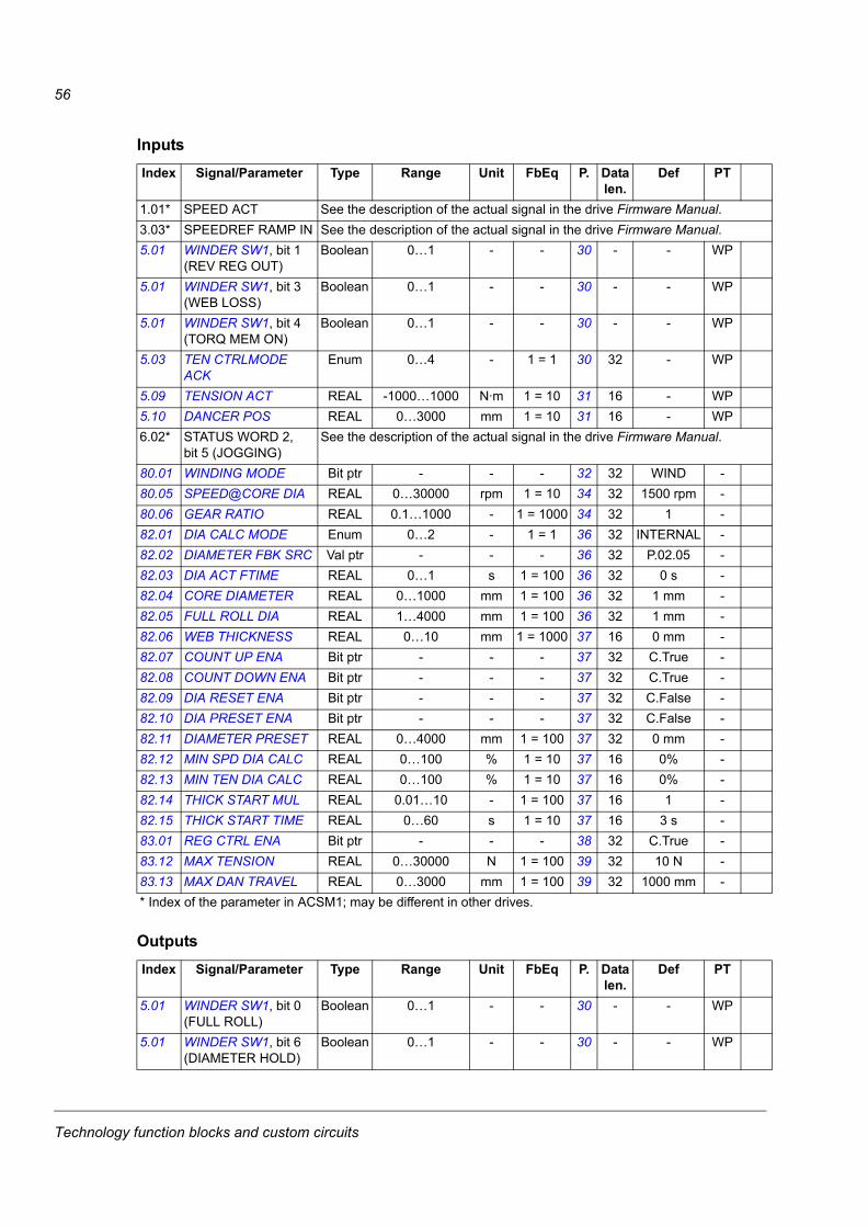
56
Inputs
Outputs
Index Signal/Parameter Type Range Unit FbEq P. Data len.
Def PT
1.01* SPEED ACT See the description of the actual signal in the drive Firmware Manual.3.03* SPEEDREF RAMP IN See the description of the actual signal in the drive Firmware Manual.5.01 WINDER SW1, bit 1
(REV REG OUT)Boolean 0…1 - - 30 - - WP
5.01 WINDER SW1, bit 3 (WEB LOSS)
Boolean 0…1 - - 30 - - WP
5.01 WINDER SW1, bit 4 (TORQ MEM ON)
Boolean 0…1 - - 30 - - WP
5.03 TEN CTRLMODE ACK
Enum 0…4 - 1 = 1 30 32 - WP
5.09 TENSION ACT REAL -1000…1000 N·m 1 = 10 31 16 - WP5.10 DANCER POS REAL 0…3000 mm 1 = 10 31 16 - WP6.02* STATUS WORD 2,
bit 5 (JOGGING)See the description of the actual signal in the drive Firmware Manual.
80.01 WINDING MODE Bit ptr - - - 32 32 WIND -80.05 SPEED@CORE DIA REAL 0…30000 rpm 1 = 10 34 32 1500 rpm -80.06 GEAR RATIO REAL 0.1…1000 - 1 = 1000 34 32 1 -82.01 DIA CALC MODE Enum 0…2 - 1 = 1 36 32 INTERNAL -82.02 DIAMETER FBK SRC Val ptr - - - 36 32 P.02.05 -82.03 DIA ACT FTIME REAL 0…1 s 1 = 100 36 32 0 s -82.04 CORE DIAMETER REAL 0…1000 mm 1 = 100 36 32 1 mm -82.05 FULL ROLL DIA REAL 1…4000 mm 1 = 100 36 32 1 mm -82.06 WEB THICKNESS REAL 0…10 mm 1 = 1000 37 16 0 mm -82.07 COUNT UP ENA Bit ptr - - - 37 32 C.True -82.08 COUNT DOWN ENA Bit ptr - - - 37 32 C.True -82.09 DIA RESET ENA Bit ptr - - - 37 32 C.False -82.10 DIA PRESET ENA Bit ptr - - - 37 32 C.False -82.11 DIAMETER PRESET REAL 0…4000 mm 1 = 100 37 32 0 mm -82.12 MIN SPD DIA CALC REAL 0…100 % 1 = 10 37 16 0% -82.13 MIN TEN DIA CALC REAL 0…100 % 1 = 10 37 16 0% -82.14 THICK START MUL REAL 0.01…10 - 1 = 100 37 16 1 -82.15 THICK START TIME REAL 0…60 s 1 = 10 37 16 3 s -83.01 REG CTRL ENA Bit ptr - - - 38 32 C.True -83.12 MAX TENSION REAL 0…30000 N 1 = 100 39 32 10 N -83.13 MAX DAN TRAVEL REAL 0…3000 mm 1 = 100 39 32 1000 mm -* Index of the parameter in ACSM1; may be different in other drives.
Index Signal/Parameter Type Range Unit FbEq P. Data len.
Def PT
5.01 WINDER SW1, bit 0 (FULL ROLL)
Boolean 0…1 - - 30 - - WP
5.01 WINDER SW1, bit 6 (DIAMETER HOLD)
Boolean 0…1 - - 30 - - WP
Technology function blocks and custom circuits

57
5.05 DIAMETER ACT REAL 0…4000 mm 1 = 100 30 32 - WP5.06 DIAMETER PERC REAL 0…200 % 1 = 10 31 16 - WP5.07 DIAMETER RATIO REAL 0…100 - 1 = 10 31 16 - WP
CORE PERC REAL 0…100 % - - - - -
Technology function blocks and custom circuits
58
FRICTION COMPTechnology block
Block diagram
DescriptionFRICTION COMP calculates the linear friction compensation term based on a predefined friction curve (see the figure on page 59). The curve is defined by dynamic friction values at 20%, 40%, 60%, 80% and 100% of the maximum speed (maximum speed for the winder with an empty roll). The term at a specific speed is the sum of the dynamic friction at this speed and the static friction.
Friction compensation is essential in the OPEN LOOP tension control.
FRICTION COMP
ERROR
TLAx x ms
ERRORFRICTION COMP 5.19 FRICTION COMP
SPEED ACT1.01 SPEED ACT
DF2085.02 FRICTION @20
80.05 SPEED@CORE DIA85.01 STATIC FRICTION
SPEED AT CORESTATIC FRICTION
DF4085.03 FRICTION @40
DF6085.04 FRICTION @6085.05 FRICTION @8085.06 FRICTION @100
DF80DF100
ABS
I2
I3
I4
I5
IN_MIN
IN_MAX
DYNFRICO
INMAX SPEED AT CORE
ACTUAL SPEED
0
I1
STATIC FRICTION
DYNAMIC FRICTION AT 100 %DYNAMIC FRICTION AT 80 %DYNAMIC FRICTION AT 60 %
DYNAMIC FRICTION AT 20 %DYNAMIC FRICTION AT 40 %
FRICTION COMPENSATION
ABS
FRICTION COMP
Technology function blocks and custom circuits
59
Inputs
Outputs
Index Signal/Parameter Type Range Unit FbEq P. Data len.
Def PT
1.01* SPEED ACT See the description of the actual signal in the drive Firmware Manual.80.05 SPEED@CORE DIA REAL 0…30000 rpm 1 = 10 34 32 1500 rpm -85.01 STATIC FRICTION REAL -1000…1000 N·m 1 = 100 42 16 0 N·m -85.02 DYN FRICTION@20 REAL -1000…1000 N·m 1 = 100 42 16 0 N·m -85.03 DYN FRICTION@40 REAL -1000…1000 N·m 1 = 100 42 16 0 N·m -85.04 DYN FRICTION@60 REAL -1000…1000 N·m 1 = 100 43 16 0 N·m -85.05 DYN FRICTION@80 REAL -1000…1000 N·m 1 = 100 43 16 0 N·m -85.06 DYN FRICTION@100 REAL -1000…1000 N·m 1 = 100 43 16 0 N·m -* Index of the parameter in ACSM1; may be different in other drives.
Index Signal/Parameter Type Range Unit FbEq P. Data len.
Def PT
5.19 FRICTION COMP REAL -2000…2000 N·m 1 = 100 32 16 - WP
Friction compensation
Friction compensation
Winder speed
Static friction
Dynamic friction
Technology function blocks and custom circuits
60
INERTIA COMPTechnology block
Block diagramSee page 61.
DescriptionINERTIA COMP calculates the inertia based on the roll diameter and material data. Alternatively, the weight of the full roll or web data is given as the input data. The block also calculates the inertia compensation derivation time from the calculated inertia and known motor nominal torque and speed.
INERTIA COMP
5.18 INRT COMP TIME
TLAx x ms
INRT COMP DER TIMEACTUAL ROLL WEIGHT
INERTIA EST 5.17 INERTIA EST
ACTUAL ROLL WEIGHT
MOT NOM SPEED99.09 MOT NOM SPEED
CORE DIAMETER82.04 CORE DIAMETER
99.12 MOT NOM TORQUE5.05 DIAMETER ACT
MOT NOM TORQUE
DIAMETER ACT
GEAR RATIO80.06 GEAR RATIO
INERTIA COMP ENA84.01 INERTIA COMP ENA
FULL ROLL WEIGHT84.04 FULL ROLL WEIGHT
84.02 ROLL WEIGHT SEL84.03 FIXED INERTIA
ROLL WEIGHT SEL
FIXED INERTIA
WEB DENSITY84.05 WEB DENSITY
WEB WIDTH84.06 WEB WIDTH
5.06 DIAMETER PERC DIAMETER PERC
FULL ROLL DIA82.05 FULL ROLL DIA
ERRC ERRC
Technology function blocks and custom circuits
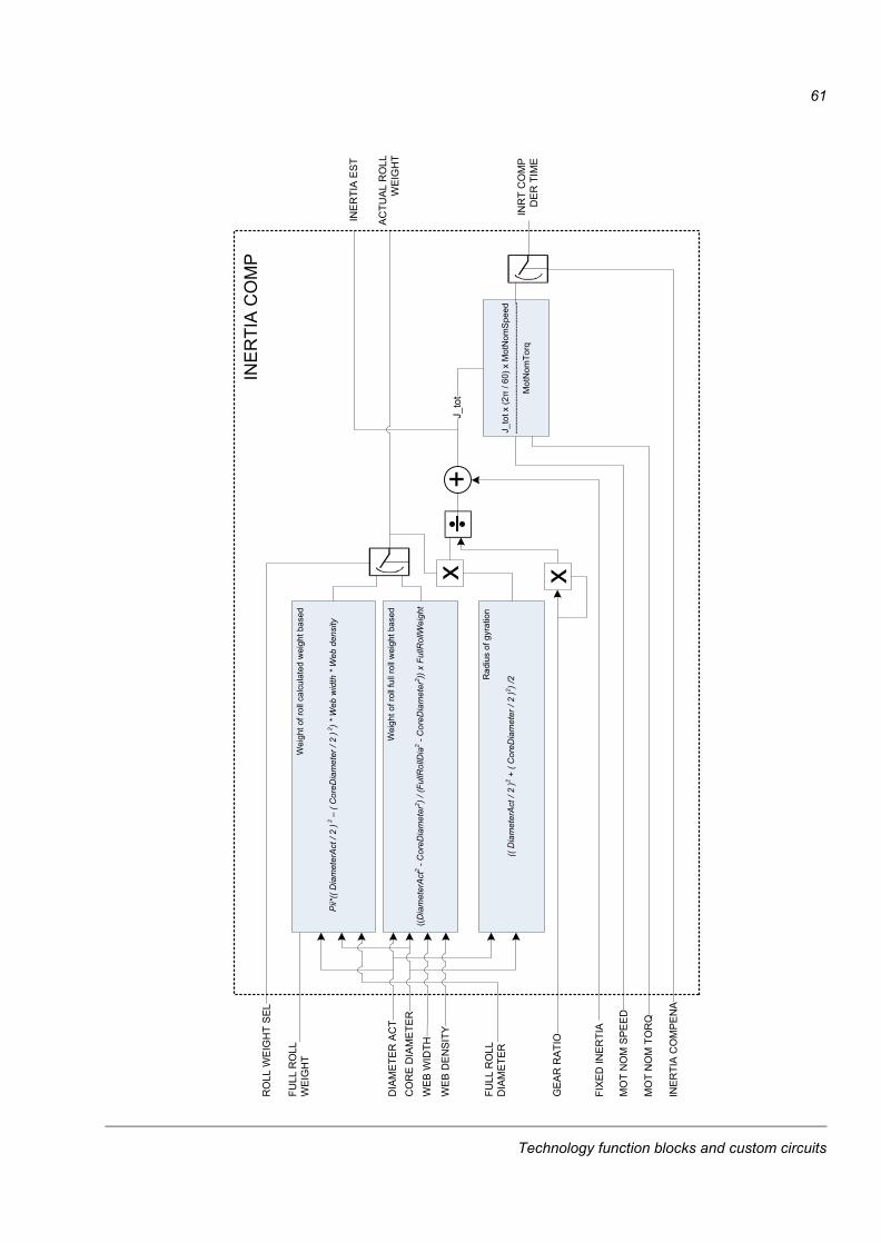
61
INE
RTI
A C
OM
PE
NA
((Dia
met
erA
ct2
-Cor
eDia
met
er2 ) /
(Ful
lRol
lDia
2-C
oreD
iam
eter
2 )) x
FullR
ollW
eigh
t
DIA
MET
ER A
CT
CO
RE
DIA
MET
ER
WEB
WID
TH
WEB
DEN
SITY
((D
iam
eter
Act
/2)2
+ (C
oreD
iam
eter
/2)2 ) /
2
Wei
ght o
f rol
l ful
l rol
l wei
ght b
ased
Rad
ius
of g
yrat
ion
FIX
ED IN
ER
TIA
GE
AR
RA
TIO
J_to
tx (2
�/ 6
0)x
Mot
Nom
Spe
ed---
-----
-----
-----
-----
-----
-----
-----
-----
--M
otN
omTo
rq
J_to
t
AC
TUA
L R
OLL
WEI
GH
T
INR
T C
OM
PD
ER
TIM
E
MO
T N
OM
SPE
ED
RO
LL W
EIG
HT
SEL
FULL
RO
LLW
EIG
HT
MO
T N
OM
TO
RQ
INE
RTI
A C
OM
P
INE
RTI
A E
ST
Pii*
((D
iam
eter
Act
/ 2 )
2–
(Cor
eDia
met
er/ 2
)2 ) *
Web
wid
th *
Web
den
sity
FULL
RO
LLD
IAM
ETER
Wei
ght o
f rol
lcal
cula
ted
wei
ght b
ased
Technology function blocks and custom circuits
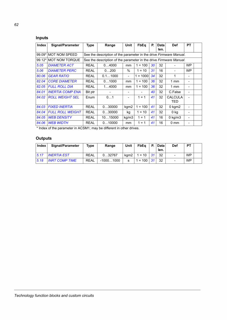
62
Inputs
Outputs
Index Signal/Parameter Type Range Unit FbEq P. Data len.
Def PT
99.09* MOT NOM SPEED See the description of the parameter in the drive Firmware Manual.99.12* MOT NOM TORQUE See the description of the parameter in the drive Firmware Manual.5.05 DIAMETER ACT REAL 0…4000 mm 1 = 100 30 32 - WP5.06 DIAMETER PERC REAL 0…200 % 1 = 10 31 16 - WP80.06 GEAR RATIO REAL 0.1…1000 - 1 = 1000 34 32 1 -82.04 CORE DIAMETER REAL 0…1000 mm 1 = 100 36 32 1 mm -82.05 FULL ROLL DIA REAL 1…4000 mm 1 = 100 36 32 1 mm -84.01 INERTIA COMP ENA Bit ptr - - - 40 32 C.False -84.02 ROLL WEIGHT SEL Enum 0…1 - 1 = 1 41 32 CALCULA
TED-
84.03 FIXED INERTIA REAL 0…30000 kgm2 1 = 100 41 32 0 kgm2 -84.04 FULL ROLL WEIGHT REAL 0…30000 kg 1 = 10 41 32 0 kg -84.05 WEB DENSITY REAL 10…15000 kg/m3 1 = 1 41 16 0 kg/m3 -84.06 WEB WIDTH REAL 0…10000 mm 1 = 1 41 16 0 mm -* Index of the parameter in ACSM1; may be different in other drives.
Index Signal/Parameter Type Range Unit FbEq P. Data len.
Def PT
5.17 INERTIA EST REAL 0…32767 kgm2 1 = 10 31 32 - WP5.18 INRT COMP TIME REAL -1000…1000 s 1 = 100 31 32 - WP
Technology function blocks and custom circuits
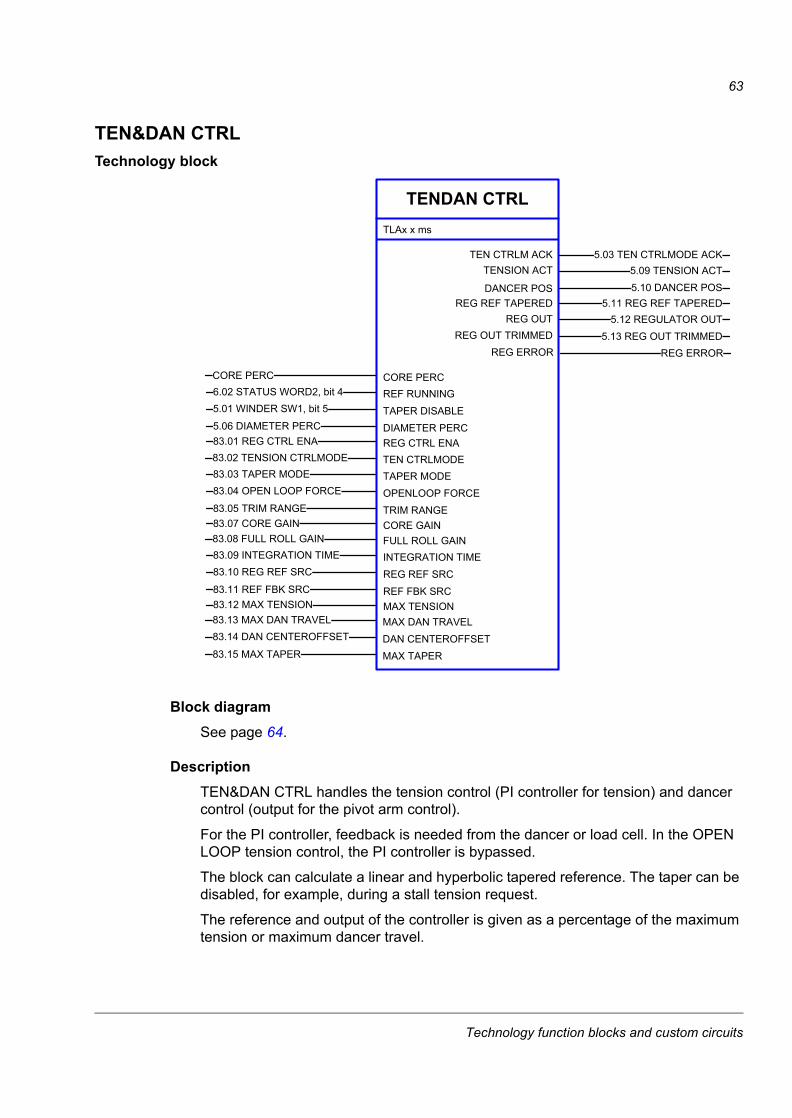
63
TEN&DAN CTRLTechnology block
Block diagramSee page 64.
DescriptionTEN&DAN CTRL handles the tension control (PI controller for tension) and dancer control (output for the pivot arm control).
For the PI controller, feedback is needed from the dancer or load cell. In the OPEN LOOP tension control, the PI controller is bypassed.
The block can calculate a linear and hyperbolic tapered reference. The taper can be disabled, for example, during a stall tension request.
The reference and output of the controller is given as a percentage of the maximum tension or maximum dancer travel.
TENDAN CTRL
5.09 TENSION ACT
TLAx x ms
TENSION ACT
DANCER POS
TEN CTRLM ACK 5.03 TEN CTRLMODE ACK
5.10 DANCER POS
CORE PERCCORE PERC
DIAMETER PERC5.06 DIAMETER PERC
6.02 STATUS WORD2, bit 45.01 WINDER SW1, bit 5
REF RUNNINGTAPER DISABLE
REG CTRL ENA83.01 REG CTRL ENA
5.12 REGULATOR OUTREG OUTREG OUT TRIMMED
REG REF TAPERED 5.11 REG REF TAPERED
5.13 REG OUT TRIMMED
TEN CTRLMODE83.02 TENSION CTRLMODE
TRIM RANGE83.05 TRIM RANGE
83.03 TAPER MODE83.04 OPEN LOOP FORCE
TAPER MODEOPENLOOP FORCE
CORE GAIN83.07 CORE GAIN
FULL ROLL GAIN83.08 FULL ROLL GAIN
REF FBK SRC83.11 REF FBK SRC
83.09 INTEGRATION TIME83.10 REG REF SRC
INTEGRATION TIMEREG REF SRC
MAX TENSION83.12 MAX TENSION
MAX TAPER83.15 MAX TAPER
83.13 MAX DAN TRAVEL83.14 DAN CENTEROFFSET
MAX DAN TRAVELDAN CENTEROFFSET
REG ERROR REG ERROR
Technology function blocks and custom circuits
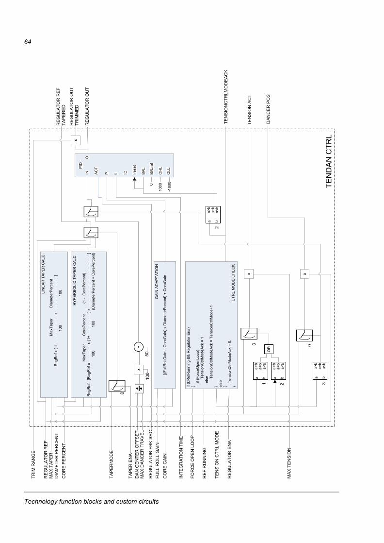
64
MaxTa
per
Dia
met
erP
erce
ntR
egR
ef x
[ 1
----
------
----
----
x -
-----
-----
-----
-----
----
]10
0
1
00
MA
X T
AP
ER
DIA
MET
ER P
ERC
ENT
CO
RE
PE
RC
EN
T
RE
GU
LATO
R R
EF
Max
Tape
rC
oreP
erce
nt(1
-C
oreP
erce
nt)
Reg
Ref
-[R
egR
ef x
----
------
---x
(1+
-----
------
----
--) x
-----
------
----
------
----
------
----
------
-]10
0 10
0(D
iam
eter
Per
cent
+ C
oreP
erce
nt)
[(Ful
lRol
lGai
n –
Cor
eGai
n) x
Dia
met
erP
erce
nt] +
Cor
eGai
nC
OR
E G
AIN
FULL
RO
LL G
AIN
IN AC
T
P tI tC Irese
t
BAL
PID
O
BAL
ref
OH
L
OLL
RE
GU
LATO
R F
BK S
RC
INTE
GR
ATIO
N T
IME
0
TEN
SIO
NC
TRLM
OD
EA
CK
a b
a>b
a=b
a<b
2
If (b
Ref
Run
ning
&&
Reg
ulat
or E
na)
{if
(For
ceO
penL
oop)
Tens
ionC
trlM
odeA
ck =
1
el
se Tens
ionC
trlM
odeA
ck =
Ten
sion
Ctrl
Mod
e+1
} else
{
Tens
ionC
trlM
odeA
ck =
0;
}
RE
F R
UN
NIN
G
TRIM
RAN
GE
xR
EGU
LATO
R O
UT
TRIM
ME
D
REG
ULA
TOR
OU
T
xTE
NS
ION
AC
Ta b
a>b
a=b
a<b
1
0
MA
X T
EN
SIO
N
x
DA
NC
ER
PO
S
a b
a>b
a=b
a<b
3
0
REG
ULA
TOR
REF
TA
PE
RE
D
MA
X D
AN
CER
TR
AVE
LD
AN
CE
NTE
R O
FFS
ET
+
50
LIN
EAR
TA
PER
CA
LC
HY
PER
BOLI
C T
AP
ER
CAL
C
GAI
N A
DA
PTAT
ION
CTR
L M
OD
E C
HE
CK
RE
GU
LATO
R E
NA
TEN
SIO
N C
TRL
MO
DE
FOR
CE
OP
EN
LO
OP
a b
a>b
a=b
a<b
2
OR
x
100
TAP
ER
MO
DE
0
TAP
ER
EN
A
1000
-100
0 TEN
DA
N C
TRL
Technology function blocks and custom circuits
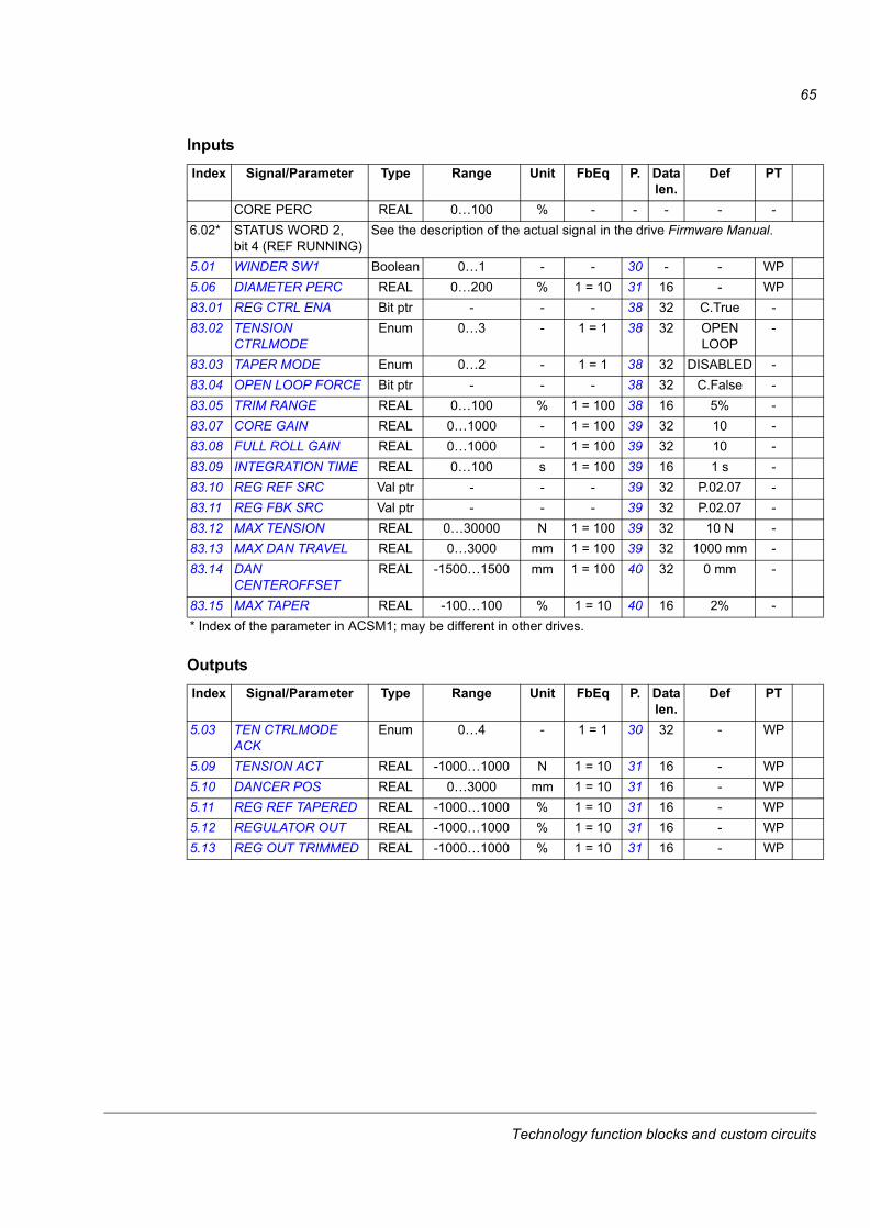
65
Inputs
Outputs
Index Signal/Parameter Type Range Unit FbEq P. Data len.
Def PT
CORE PERC REAL 0…100 % - - - - -6.02* STATUS WORD 2,
bit 4 (REF RUNNING)See the description of the actual signal in the drive Firmware Manual.
5.01 WINDER SW1 Boolean 0…1 - - 30 - - WP5.06 DIAMETER PERC REAL 0…200 % 1 = 10 31 16 - WP83.01 REG CTRL ENA Bit ptr - - - 38 32 C.True -83.02 TENSION
CTRLMODEEnum 0…3 - 1 = 1 38 32 OPEN
LOOP-
83.03 TAPER MODE Enum 0…2 - 1 = 1 38 32 DISABLED -83.04 OPEN LOOP FORCE Bit ptr - - - 38 32 C.False -83.05 TRIM RANGE REAL 0…100 % 1 = 100 38 16 5% -83.07 CORE GAIN REAL 0…1000 - 1 = 100 39 32 10 -83.08 FULL ROLL GAIN REAL 0…1000 - 1 = 100 39 32 10 -83.09 INTEGRATION TIME REAL 0…100 s 1 = 100 39 16 1 s -83.10 REG REF SRC Val ptr - - - 39 32 P.02.07 -83.11 REG FBK SRC Val ptr - - - 39 32 P.02.07 -83.12 MAX TENSION REAL 0…30000 N 1 = 100 39 32 10 N -83.13 MAX DAN TRAVEL REAL 0…3000 mm 1 = 100 39 32 1000 mm -83.14 DAN
CENTEROFFSETREAL -1500…1500 mm 1 = 100 40 32 0 mm -
83.15 MAX TAPER REAL -100…100 % 1 = 10 40 16 2% -* Index of the parameter in ACSM1; may be different in other drives.
Index Signal/Parameter Type Range Unit FbEq P. Data len.
Def PT
5.03 TEN CTRLMODE ACK
Enum 0…4 - 1 = 1 30 32 - WP
5.09 TENSION ACT REAL -1000…1000 N 1 = 10 31 16 - WP5.10 DANCER POS REAL 0…3000 mm 1 = 10 31 16 - WP5.11 REG REF TAPERED REAL -1000…1000 % 1 = 10 31 16 - WP5.12 REGULATOR OUT REAL -1000…1000 % 1 = 10 31 16 - WP5.13 REG OUT TRIMMED REAL -1000…1000 % 1 = 10 31 16 - WP
Technology function blocks and custom circuits
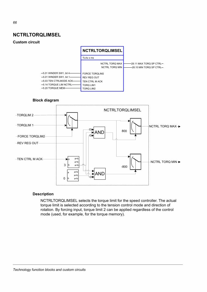
66
NCTRLTORQLIMSELCustom circuit
Block diagram
DescriptionNCTRLTORQLIMSEL selects the torque limit for the speed controller. The actual torque limit is selected according to the tension control mode and direction of rotation. By forcing input, torque limit 2 can be applied regardless of the control mode (used, for example, for the torque memory).
NCTRLTORQLIMSEL
28.10 MIN TORQ SP CTRL
TLAx x ms
NCTRL TORQ MINNCTRL TORQ MAX 28.11 MAX TORQ SP CTRL
FORCE TORQLIM25.01 WINDER SW1, bit 4
TORQ LIM25.20 TORQUE MEM
5.01 WINDER SW1, bit 15.03 TEN CTRLMODE ACK
REV REG OUT
TEN CTRL M ACK5.14 TORQUE LIM NCTRL TORQ LIM1
NCTRLTORQLIMSEL
TORQLIM 1
TORQLIM 2
FORCE TORQLIM2
NCTRL TORQ MAX
NCTRL TORQ MIN
800
-800
AND
TEN CTRL M ACK a
b
a>ba=ba<b3
AND
a
b
a>ba=ba<b0
REV REG OUT
Technology function blocks and custom circuits
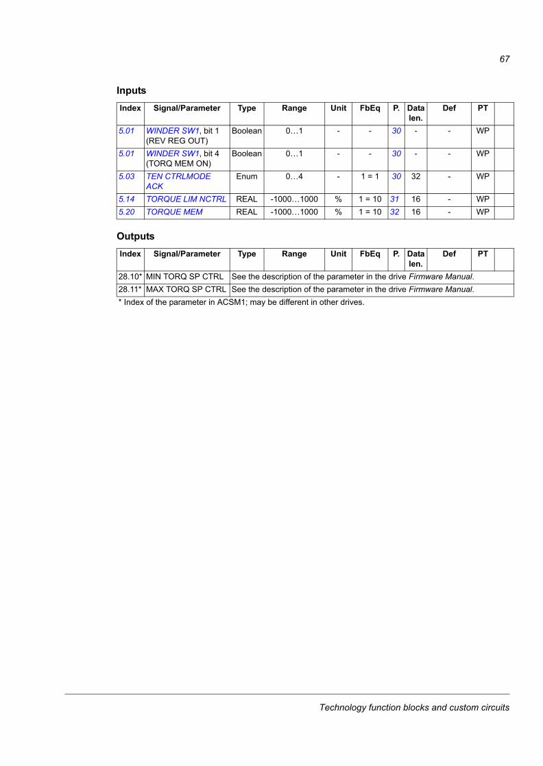
67
Inputs
Outputs
Index Signal/Parameter Type Range Unit FbEq P. Data len.
Def PT
5.01 WINDER SW1, bit 1 (REV REG OUT)
Boolean 0…1 - - 30 - - WP
5.01 WINDER SW1, bit 4 (TORQ MEM ON)
Boolean 0…1 - - 30 - - WP
5.03 TEN CTRLMODE ACK
Enum 0…4 - 1 = 1 30 32 - WP
5.14 TORQUE LIM NCTRL REAL -1000…1000 % 1 = 10 31 16 - WP5.20 TORQUE MEM REAL -1000…1000 % 1 = 10 32 16 - WP
Index Signal/Parameter Type Range Unit FbEq P. Data len.
Def PT
28.10* MIN TORQ SP CTRL See the description of the parameter in the drive Firmware Manual.28.11* MAX TORQ SP CTRL See the description of the parameter in the drive Firmware Manual.* Index of the parameter in ACSM1; may be different in other drives.
Technology function blocks and custom circuits
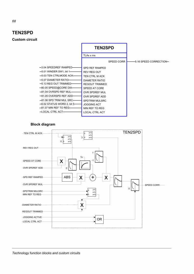
68
TEN2SPDCustom circuit
Block diagram
TEN2SPDTLAx x ms
SPEED CORR 5.16 SPEED CORRECTION
SPD REF RAMPED3.04 SPEEDREF RAMPED
DIAMETER RATIO5.07 DIAMETER RATIO
5.01 WINDER SW1, bit 15.03 TEN CTRLMODE ACK
REV REG OUTTEN CTRL M ACK
REGOUT TRIMMED5.13 REG OUT TRIMMED
SPEED AT CORE80.05 SPEED@CORE DIA
SPDTRIM MULSRC81.06 SPD TRIM MUL SRC
81.04 OVRSPD REF MUL81.05 OVERSPD REF ADD
OVR SPDREF MULOVR SPDREF ADD
JOGGING ACT6.02 STATUS WORD 2, bit 5
MIN REF TO REG81.07 MIN REF TO REGLOCAL CTRL ACT LOCAL CTRL ACT
REGOUT TRIMMED
TEN CTRL M ACK a
b
a>ba=ba<b3
DIAMETER RATIO
SPD REF RAMPED
OVR SPDREF MUL
1
-1
REV REG OUT
0
1s
SPEED AT CORE
a
b
a>ba=ba<b0
OVR SPDREF ADD
ABS
0SPEED CORR
ORJOGGING ACTIVE
LOCAL CTRL ACT
TEN2SPD
SPDTRIM MULSRC a
b
a>ba=ba<bMIN REF TO REG
Technology function blocks and custom circuits
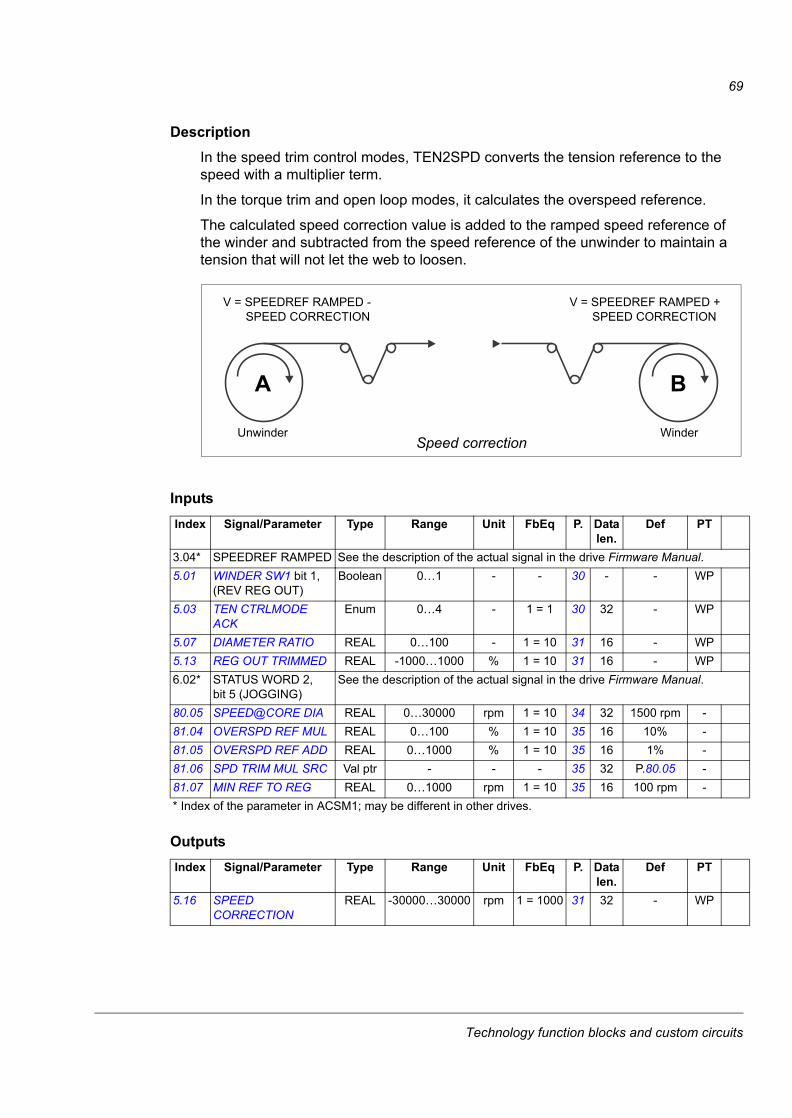
69
DescriptionIn the speed trim control modes, TEN2SPD converts the tension reference to the speed with a multiplier term.
In the torque trim and open loop modes, it calculates the overspeed reference.
The calculated speed correction value is added to the ramped speed reference of the winder and subtracted from the speed reference of the unwinder to maintain a tension that will not let the web to loosen.
Inputs
Outputs
Index Signal/Parameter Type Range Unit FbEq P. Data len.
Def PT
3.04* SPEEDREF RAMPED See the description of the actual signal in the drive Firmware Manual.5.01 WINDER SW1 bit 1,
(REV REG OUT)Boolean 0…1 - - 30 - - WP
5.03 TEN CTRLMODE ACK
Enum 0…4 - 1 = 1 30 32 - WP
5.07 DIAMETER RATIO REAL 0…100 - 1 = 10 31 16 - WP5.13 REG OUT TRIMMED REAL -1000…1000 % 1 = 10 31 16 - WP6.02* STATUS WORD 2,
bit 5 (JOGGING)See the description of the actual signal in the drive Firmware Manual.
80.05 SPEED@CORE DIA REAL 0…30000 rpm 1 = 10 34 32 1500 rpm -81.04 OVERSPD REF MUL REAL 0…100 % 1 = 10 35 16 10% -81.05 OVERSPD REF ADD REAL 0…1000 % 1 = 10 35 16 1% -81.06 SPD TRIM MUL SRC Val ptr - - - 35 32 P.80.05 -81.07 MIN REF TO REG REAL 0…1000 rpm 1 = 10 35 16 100 rpm -* Index of the parameter in ACSM1; may be different in other drives.
Index Signal/Parameter Type Range Unit FbEq P. Data len.
Def PT
5.16 SPEED CORRECTION
REAL -30000…30000 rpm 1 = 1000 31 32 - WP
A B
Unwinder Winder
V = SPEEDREF RAMPED - SPEED CORRECTION
V = SPEEDREF RAMPED + SPEED CORRECTION
Speed correction
Technology function blocks and custom circuits
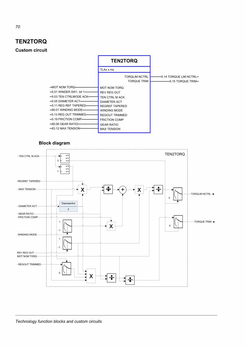
70
TEN2TORQCustom circuit
Block diagram
TEN2TORQ
5.15 TORQUE TRIM
TLAx x ms
TORQUE TRIMTORQLIM NCTRL 5.14 TORQUE LIM NCTRL
MOT NOM TORQMOT NOM TORQ
REGREF TAPERED5.11 REG REF TAPERED
5.01 WINDER SW1, bit 15.03 TEN CTRLMODE ACK
REV REG OUT
TEN CTRL M ACK
WINDING MODE80.01 WINDING MODE
REGOUT TRIMMED5.13 REG OUT TRIMMED
MAX TENSION83.12 MAX TENSION
5.19 FRICTION COMP80.06 GEAR RATIO
FRICTION COMP
GEAR RATIO
5.05 DIAMETER ACT DIAMETER ACT
TEN2TORQ
xREGREF TAPERED
DiameterAct--------------------
2DIAMETER ACT
GEAR RATIO
+
FRICTION COMP
x
REV REG OUT
1
-1
MOT NOM TORQ
TORQLIM NCTRL
x
REGOUT TRIMMED
MAX TENSION
0
TEN CTRL M ACK
0
a
b
a>ba=ba<b3
a
b
a>ba=ba<b1
WINDING MODE
1
-1x 0
TORQUE TRIM
Technology function blocks and custom circuits
71
DescriptionTEN2TORQ converts the percent scaled tension reference to the motor torque.
It also calculates the torque limit of the speed controller (tension reference + friction compensation term).
Inputs
Outputs
Index Signal/Parameter Type Range Unit FbEq P. Data len.
Def PT
5.01 WINDER SW1, bit 1 (REV REG OUT)
Boolean 0…1 - - 30 - - WP
5.03 TEN CTRLMODE ACK
Enum 0…4 - 1 = 1 30 32 - WP
5.05 DIAMETER ACT REAL 0…4000 mm 1 = 100 30 32 - WP5.11 REG REF TAPERED REAL -1000…1000 % 1 = 10 31 16 - WP5.13 REG OUT TRIMMED REAL -1000…1000 % 1 = 10 31 16 - WP5.19 FRICTION COMP REAL -2000…2000 N·m 1 = 100 32 16 - WP80.01 WINDING MODE Bit ptr - - - 32 32 WIND -80.06 GEAR RATIO REAL 0.1…1000 - 1 = 1000 34 32 1 -83.12 MAX TENSION REAL 0…30000 N 1 = 100 39 32 10 N -
Index Signal/Parameter Type Range Unit FbEq P. Data len.
Def PT
5.14 TORQUE LIM NCTRL REAL -1000…1000 % 1 = 10 31 16 - WP5.15 TORQUE TRIM REAL -1000…1000 % 1 = 10 31 16 - WP
Technology function blocks and custom circuits
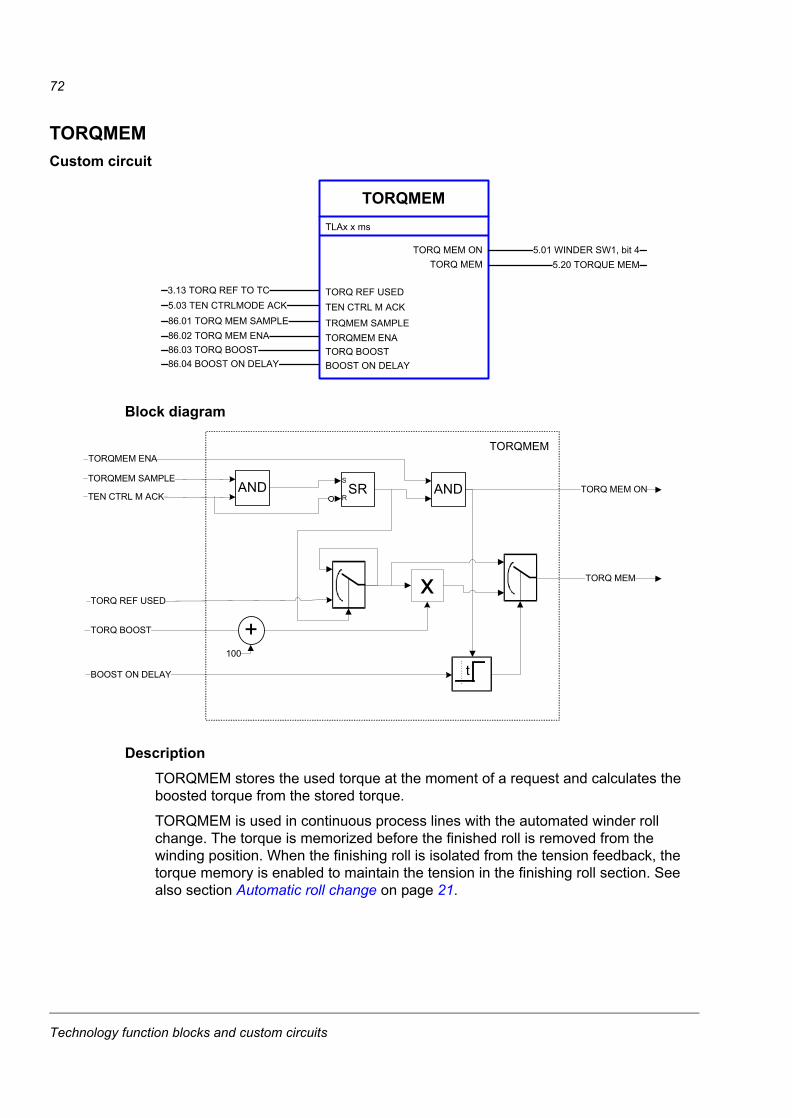
72
TORQMEMCustom circuit
Block diagram
DescriptionTORQMEM stores the used torque at the moment of a request and calculates the boosted torque from the stored torque.
TORQMEM is used in continuous process lines with the automated winder roll change. The torque is memorized before the finished roll is removed from the winding position. When the finishing roll is isolated from the tension feedback, the torque memory is enabled to maintain the tension in the finishing roll section. See also section Automatic roll change on page 21.
TORQMEM
5.20 TORQUE MEM
TLAx x ms
TORQ MEMTORQ MEM ON 5.01 WINDER SW1, bit 4
TORQ REF USED3.13 TORQ REF TO TC
TORQ BOOST86.03 TORQ BOOST
5.03 TEN CTRLMODE ACK86.01 TORQ MEM SAMPLE
TEN CTRL M ACK
TRQMEM SAMPLE
BOOST ON DELAY86.04 BOOST ON DELAY
86.02 TORQ MEM ENA TORQMEM ENA
�������
�
����������
������ ������
������������ ���
�
��
�������������
����������
����������
��������� ��
��������
����
�
Technology function blocks and custom circuits
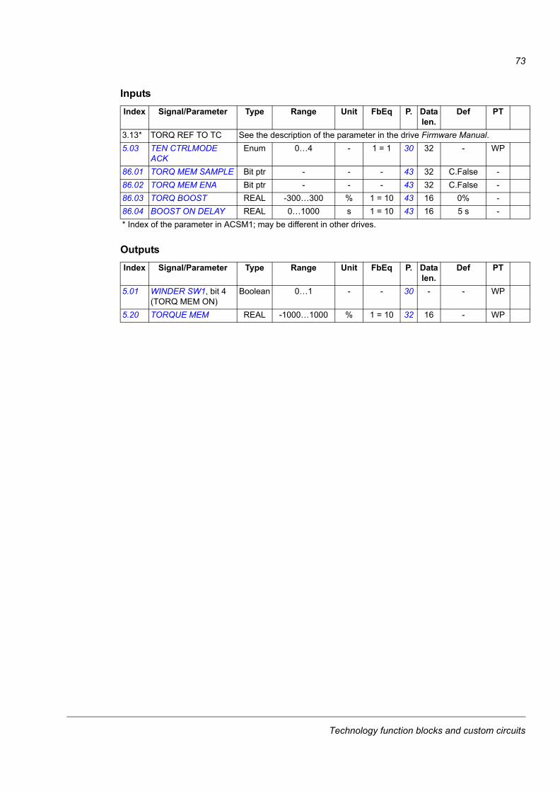
73
Inputs
Outputs
Index Signal/Parameter Type Range Unit FbEq P. Data len.
Def PT
3.13* TORQ REF TO TC See the description of the parameter in the drive Firmware Manual.5.03 TEN CTRLMODE
ACKEnum 0…4 - 1 = 1 30 32 - WP
86.01 TORQ MEM SAMPLE Bit ptr - - - 43 32 C.False -86.02 TORQ MEM ENA Bit ptr - - - 43 32 C.False -86.03 TORQ BOOST REAL -300…300 % 1 = 10 43 16 0% -86.04 BOOST ON DELAY REAL 0…1000 s 1 = 10 43 16 5 s -* Index of the parameter in ACSM1; may be different in other drives.
Index Signal/Parameter Type Range Unit FbEq P. Data len.
Def PT
5.01 WINDER SW1, bit 4 (TORQ MEM ON)
Boolean 0…1 - - 30 - - WP
5.20 TORQUE MEM REAL -1000…1000 % 1 = 10 32 16 - WP
Technology function blocks and custom circuits
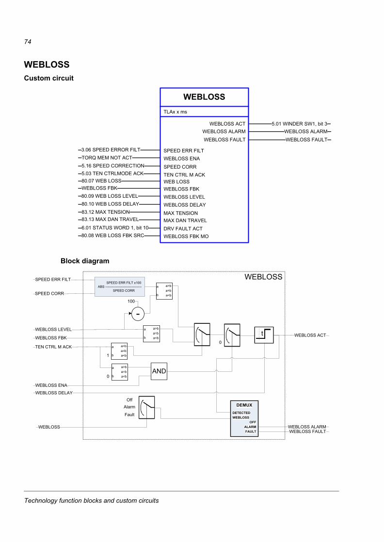
74
WEBLOSSCustom circuit
Block diagram
WEBLOSSTLAx x ms
WEBLOSS ACT 5.01 WINDER SW1, bit 3
SPEED ERR FILT3.06 SPEED ERROR FILT
WEB LOSS80.07 WEB LOSS
TORQ MEM NOT ACT5.16 SPEED CORRECTION
WEBLOSS ENA
SPEED CORR
WEBLOSS FBKWEBLOSS FBK
WEBLOSS LEVEL80.09 WEB LOSS LEVEL
MAX DAN TRAVEL83.13 MAX DAN TRAVEL
80.10 WEB LOSS DELAY83.12 MAX TENSION
WEBLOSS DELAY
MAX TENSION
DRV FAULT ACT6.01 STATUS WORD 1, bit 10
WEBLOSS FBK MO80.08 WEB LOSS FBK SRC
5.03 TEN CTRLMODE ACK TEN CTRL M ACK
WEBLOSS ALARM WEBLOSS ALARMWEBLOSS FAULT WEBLOSS FAULT
TEN CTRL M ACK a
b
a>ba=ba<b1
WEBLOSS FBK
a
b
a>ba=ba<b
WEBLOSS LEVELt
WEBLOSS DELAY
WEBLOSS ACT0
a
b
a>ba=ba<b0
AND
WEBLOSS ENA
SPEED ERR FILT x100 ABS ---------------------------------
SPEED CORRa
b
a>ba=ba<b
100
SPEED ERR FILT
SPEED CORR
WEBLOSS
WEBLOSS
Alarm
Fault
OffDEMUX
OFFALARMFAULT
DETECTEDWEBLOSS
WEBLOSS ALARMWEBLOSS FAULT
Technology function blocks and custom circuits
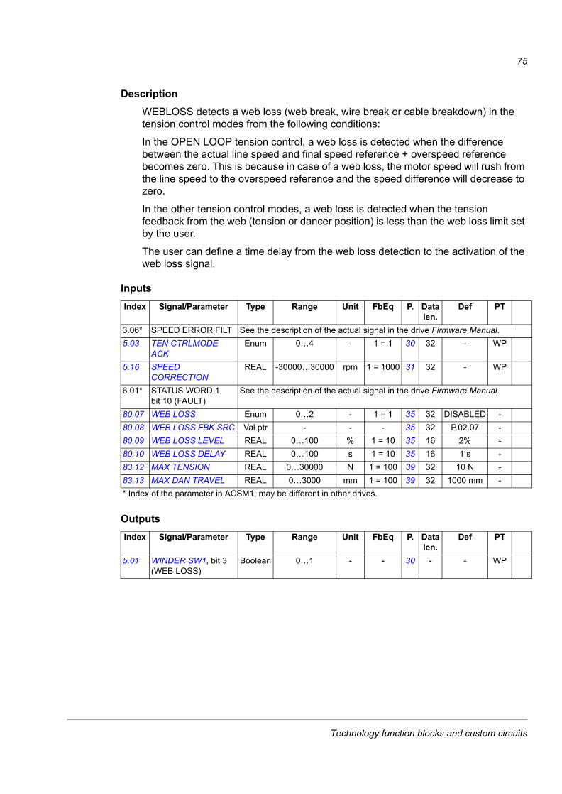
75
DescriptionWEBLOSS detects a web loss (web break, wire break or cable breakdown) in the tension control modes from the following conditions:
In the OPEN LOOP tension control, a web loss is detected when the difference between the actual line speed and final speed reference + overspeed reference becomes zero. This is because in case of a web loss, the motor speed will rush from the line speed to the overspeed reference and the speed difference will decrease to zero.
In the other tension control modes, a web loss is detected when the tension feedback from the web (tension or dancer position) is less than the web loss limit set by the user.
The user can define a time delay from the web loss detection to the activation of the web loss signal.
Inputs
Outputs
Index Signal/Parameter Type Range Unit FbEq P. Data len.
Def PT
3.06* SPEED ERROR FILT See the description of the actual signal in the drive Firmware Manual.5.03 TEN CTRLMODE
ACKEnum 0…4 - 1 = 1 30 32 - WP
5.16 SPEED CORRECTION
REAL -30000…30000 rpm 1 = 1000 31 32 - WP
6.01* STATUS WORD 1, bit 10 (FAULT)
See the description of the actual signal in the drive Firmware Manual.
80.07 WEB LOSS Enum 0…2 - 1 = 1 35 32 DISABLED -80.08 WEB LOSS FBK SRC Val ptr - - - 35 32 P.02.07 -80.09 WEB LOSS LEVEL REAL 0…100 % 1 = 10 35 16 2% -80.10 WEB LOSS DELAY REAL 0…100 s 1 = 10 35 16 1 s -83.12 MAX TENSION REAL 0…30000 N 1 = 100 39 32 10 N -83.13 MAX DAN TRAVEL REAL 0…3000 mm 1 = 100 39 32 1000 mm -* Index of the parameter in ACSM1; may be different in other drives.
Index Signal/Parameter Type Range Unit FbEq P. Data len.
Def PT
5.01 WINDER SW1, bit 3 (WEB LOSS)
Boolean 0…1 - - 30 - - WP
Technology function blocks and custom circuits
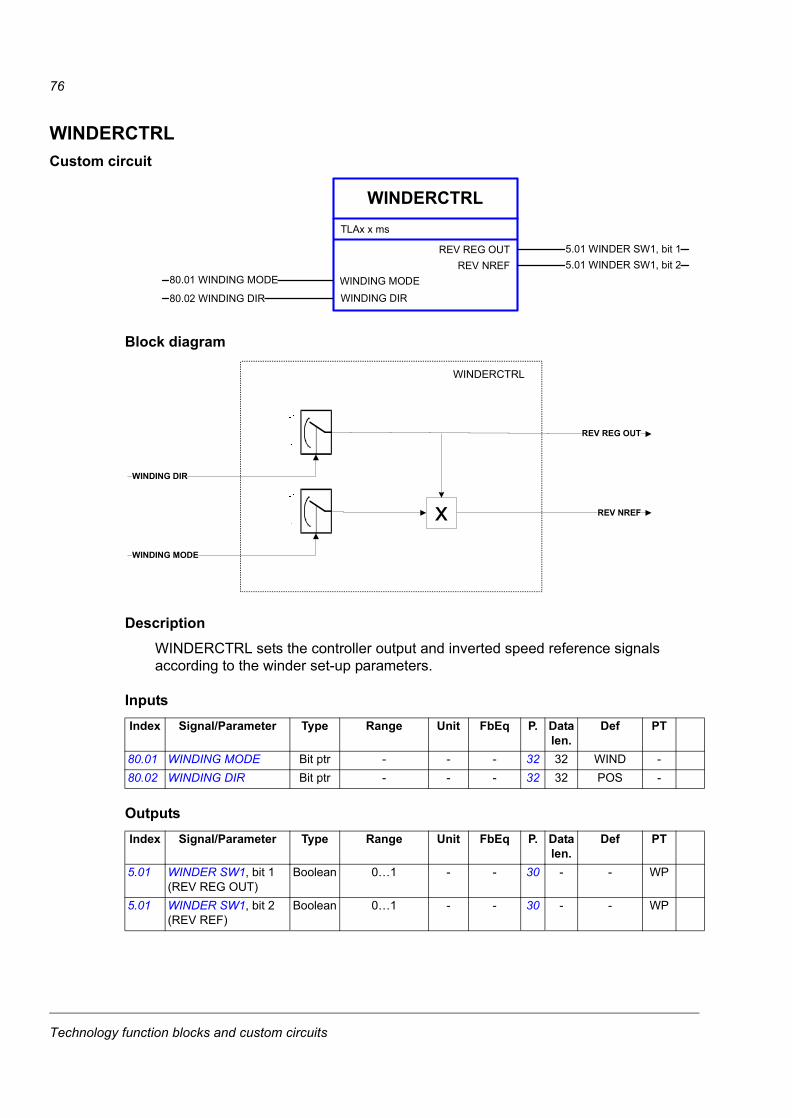
76
WINDERCTRLCustom circuit
Block diagram
DescriptionWINDERCTRL sets the controller output and inverted speed reference signals according to the winder set-up parameters.
Inputs
Outputs
Index Signal/Parameter Type Range Unit FbEq P. Data len.
Def PT
80.01 WINDING MODE Bit ptr - - - 32 32 WIND -80.02 WINDING DIR Bit ptr - - - 32 32 POS -
Index Signal/Parameter Type Range Unit FbEq P. Data len.
Def PT
5.01 WINDER SW1, bit 1 (REV REG OUT)
Boolean 0…1 - - 30 - - WP
5.01 WINDER SW1, bit 2 (REV REF)
Boolean 0…1 - - 30 - - WP
�����������
��������
����������������������
���� ��������
!������������"�#$���
� �����%&
�������
������� !������������"�#$��
�������
�����������
�� �������
������������
�� �������
Technology function blocks and custom circuits
77
WINDERREFMODCustom circuit
Block diagram
DescriptionWINDERREFMOD calculates the speed reference and acceleration and deceleration times according to the actual roll diameter.
WINDERREFMOD
25.03 ACC TIME
TLAx x ms
ACCTIME DIACOMPSPDREF DIACOMP 5.08 SPD REF DIA COMP
SPEED REF IN3.03 SPEEDREF RAMP IN
PROCESS STOP80.03 PROCESS STOP
5.01 WINDER SW1, bit 2SPEED REF ADD
REV REF
ACC TIME81.01 ACC TIME
DEC TIME81.02 DEC TIME
LOCAL CTRL ACTLOCAL CTRL ACT
81.03 PROCESS STP TIME6.02 STATUS WORD 2, bit 5
PROCESSSTPTIME
SW2 JOG ACT
5.07 DIAMETER RATIO DIAMETER RATIO
25.04 DEC TIMEDECTIME DIACOMP
SPEED REF ADD
DIAMETER RATIO
SPEED REF IN
ACC TIMEACCTIME DIACOMP
DECTIME DIACOMPPROCESSSTPTIME
DEC TIME
PROCESS STOP
ABS
REV REF
1
-1
SPDREF DIACOMP
ORJOGGING ACT
LOCAL CTRL ACT
WINDERREFMOD
1
1
Technology function blocks and custom circuits
78
Inputs
Outputs
Index Signal/Parameter Type Range Unit FbEq P. Data len.
Def PT
3.03* SPEEDREF RAMP IN See the description of the actual signal in the drive Firmware Manual.6.02* STATUS WORD 2,
bit 5 (JOGGING)See the description of the actual signal in the drive Firmware Manual.
5.01 WINDER SW1, bit 2 (REV REF)
Boolean 0…1 - - 30 - - WP
5.07 DIAMETER RATIO REAL 0…100 - 1 = 10 31 16 - WP80.03 PROCESS STOP Bit ptr - - - 33 32 C.True -81.01 ACC TIME REAL 0…1800 s 1 = 100 35 32 5 s -81.02 DEC TIME REAL 0…1800 s 1 = 100 35 32 5 s -81.03 PROCESS STP TIME REAL 0…1800 s 1 = 100 35 32 5 s -* Index of the parameter in ACSM1; may be different in other drives.
Index Signal/Parameter Type Range Unit FbEq P. Data len.
Def PT
5.08 SPD REF DIA COMP REAL -30000…30000 rpm 1 = 1000 31 32 - WP25.03* ACC TIME See the description of the parameter in the drive Firmware Manual.25.04* DEC TIME See the description of the parameter in the drive Firmware Manual.* Index of the parameter in ACSM1; may be different in other drives.
Technology function blocks and custom circuits
79
WINDERSTALLCustom circuit
Block diagram
WINDERSTALL
REG REF
TLAx x ms
REG REFSTALL ACTIVE WINDER SW1, bit 5
SPEEDREF USED5.08 SPD REF DIA COMP
FULL ROLL GAIN83.08 FULL ROLL GAIN
80.05 SPEED@CORE DIA83.06 STALL ENA
SPEED AT CORE
STALL ENA
NORMREG INT TM83.09 INTEGRATION TIME
REGULATOR REF83.10 REG REF SRC
STALLREG GAIN83.18 STALL REG GAIN
83.16 REG STALL REF83.17 STALL SPEED
REG STALL REF
STALL SPEED
83.07 CORE GAIN CORE GAIN
CORE GAINCORE GAIN
STALREG INT TM83.19 STALL INT TIME
FULL ROLL GAINFULL ROLL GAINREG INT TIMEREG INT TIME
�������
��� �����
�����������
'
#
'(#')#'*#
�
��� ���
���� ��������
������� ����
��������
��� �������
������������
��� ���������
�������
��������
�����������
��� ������������������� �
���
�� ��� ����
�� ��� ����
Technology function blocks and custom circuits
80
DescriptionWINDERSTALL selects the speed reference and the controller parameters according to the stall activation request. Stall values are used instead of the normal ones when stall enable is activated.
Stall is used, for example, when threading web material through a machine (low speed and tension reference) and for a machinery standstill.
Inputs
Outputs
Index Signal/Parameter Type Range Unit FbEq P. Data len.
Def PT
5.08 SPD REF DIA COMP REAL -30000…30000 rpm 1 = 1000 31 32 - WP80.05 SPEED@CORE DIA REAL 0…30000 rpm 1 = 10 34 32 1500 rpm -83.06 STALL ENA Bit ptr - - - 39 32 C.False -83.07 CORE GAIN REAL 0…1000 - 1 = 100 39 32 10 -83.08 FULL ROLL GAIN REAL 0…1000 - 1 = 100 39 32 10 -83.09 INTEGRATION TIME REAL 0…100 s 1 = 100 39 16 1 s -83.10 REG REF SRC Val ptr - - - 39 32 P.02.07 -83.16 REG STALL REF REAL 0…100 % 1 = 10 40 16 0% -83.17 STALL SPEED REAL 0…100 % 1 = 10 40 16 0% -83.18 STALL REG GAIN REAL 0…1000 - 1 = 100 40 32 10 -83.19 STALL INT TIME REAL 0…100 s 1 = 100 40 16 1 s -* Index of the parameter in ACSM1; may be different in other drives.
Index Signal/Parameter Type Range Unit FbEq P. Data len.
Def PT
5.01 WINDER SW1, bit 5 (STALL ACTIVE)
Boolean 0…1 - - 30 - - WP
REG REF REAL 0…100 % - - - - -CORE GAIN REAL 0…1000 - - - - - -FULL ROLL GAIN REAL 0…1000 - - - - - -REG INT TIME REAL 0…100 s - - - - -
Technology function blocks and custom circuits
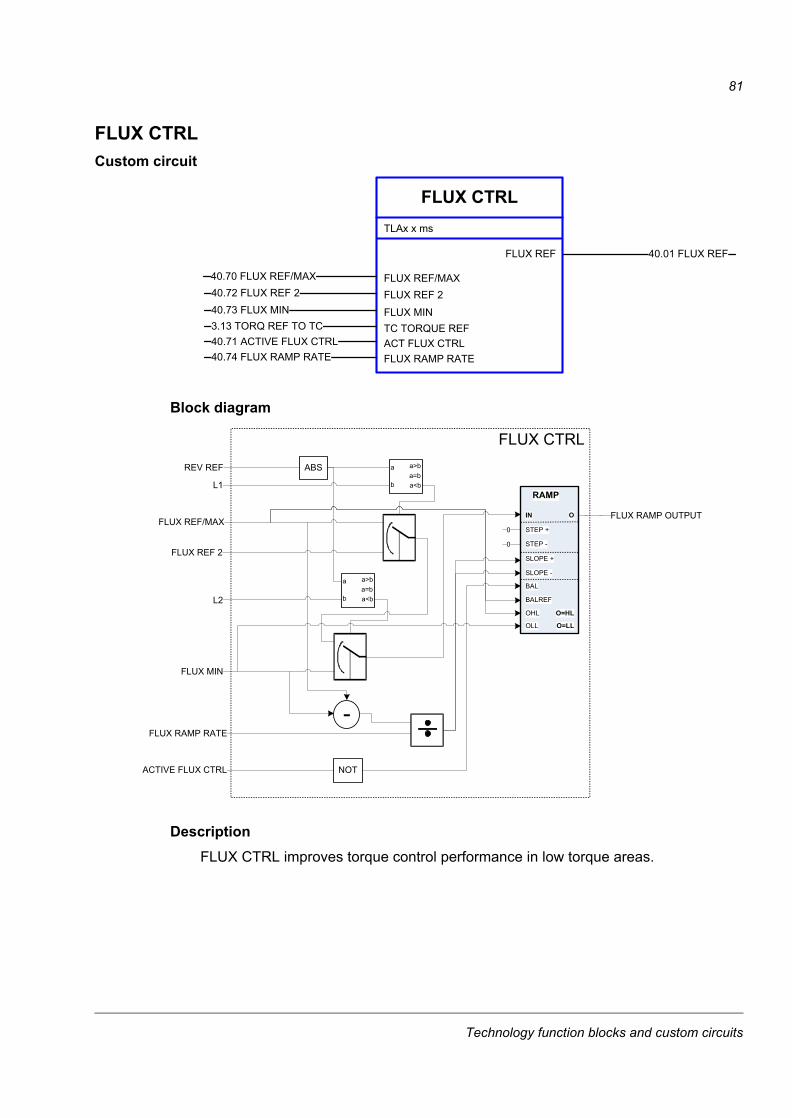
81
FLUX CTRLCustom circuit
Block diagram
DescriptionFLUX CTRL improves torque control performance in low torque areas.
FLUX CTRLTLAx x ms
FLUX REF 40.01 FLUX REF
FLUX REF/MAX40.70 FLUX REF/MAX
ACT FLUX CTRL40.71 ACTIVE FLUX CTRL
40.72 FLUX REF 240.73 FLUX MIN
FLUX REF 2
FLUX MIN
FLUX RAMP RATE40.74 FLUX RAMP RATE
3.13 TORQ REF TO TC TC TORQUE REF
ABSREV REF a
b
a>ba=ba<bL1
FLUX REF/MAX
FLUX REF 2
a
b
a>ba=ba<bL2
FLUX MIN
FLUX RAMP RATE
IN
SLOPE +
SLOPE -
BAL
BALREF
OHL
OLL
RAMP
O
STEP +
STEP -
NOTACTIVE FLUX CTRL
0
0
O=HL
O=LL
FLUX RAMP OUTPUT
FLUX CTRL
Technology function blocks and custom circuits
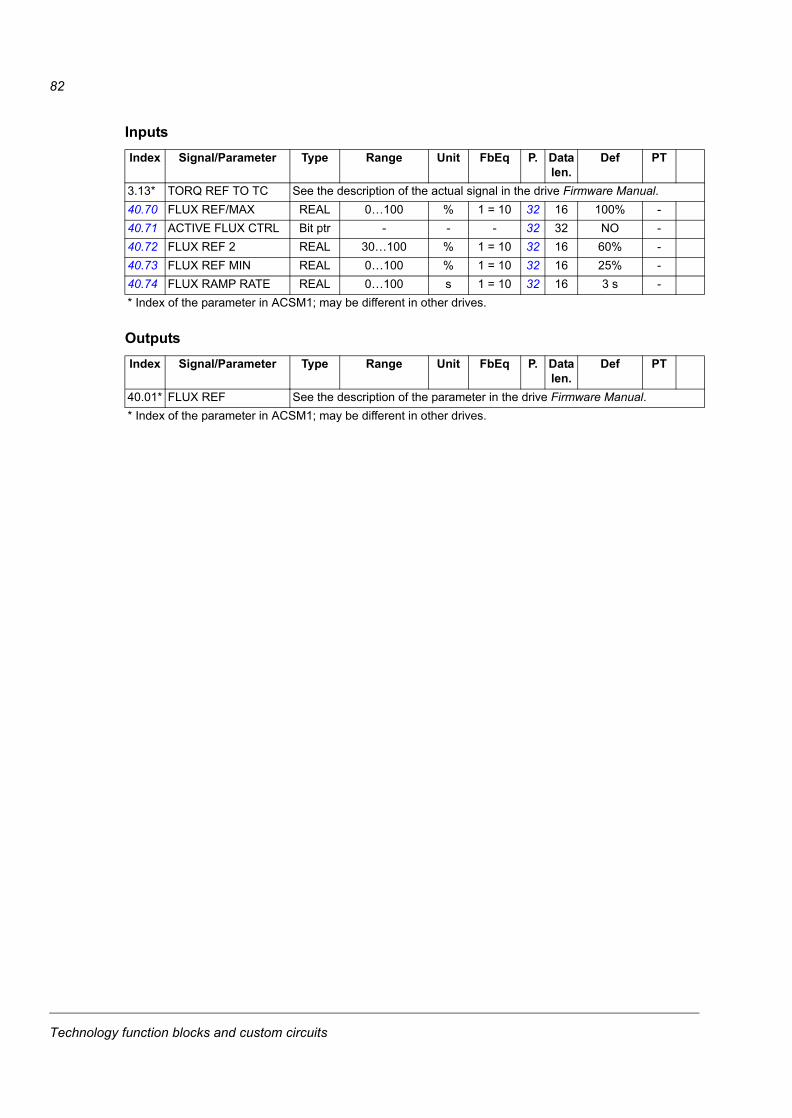
82
Inputs
Outputs
Index Signal/Parameter Type Range Unit FbEq P. Data len.
Def PT
3.13* TORQ REF TO TC See the description of the actual signal in the drive Firmware Manual.40.70 FLUX REF/MAX REAL 0…100 % 1 = 10 32 16 100% -40.71 ACTIVE FLUX CTRL Bit ptr - - - 32 32 NO -40.72 FLUX REF 2 REAL 30…100 % 1 = 10 32 16 60% -40.73 FLUX REF MIN REAL 0…100 % 1 = 10 32 16 25% -40.74 FLUX RAMP RATE REAL 0…100 s 1 = 10 32 16 3 s -* Index of the parameter in ACSM1; may be different in other drives.
Index Signal/Parameter Type Range Unit FbEq P. Data len.
Def PT
40.01* FLUX REF See the description of the parameter in the drive Firmware Manual.* Index of the parameter in ACSM1; may be different in other drives.
Technology function blocks and custom circuits

83
Fault tracing
What this chapter containsThe chapter lists the alarm and fault messages generated by the winder control program only. The messages are listed with the possible cause and corrective actions. For the listing of other alarm and fault messages, see the drive Firmware Manual.
Safety
WARNING! Only qualified electricians are allowed to maintain the drive. Read the Safety Instructions on the first pages of the drive Firmware Manual before you start working with the drive.
Alarm and fault indicationsAn alarm or a fault message indicates an abnormal drive status. You can identify and correct most alarm and fault causes using this information. If not, contact an ABB representative.
The four-digit code number in brackets after the message is for the fieldbus communication.
The alarm/fault code is displayed on the 7-segment display of the drive. The following table describes the indications given by the 7-segment display.
How to resetThe drive can be reset either by pressing the reset key on the PC tool ( ) or control panel (RESET) or switching the supply voltage off for a while. When the fault has been removed, the motor can be restarted.
A fault can also be reset from an external source by parameter 10.08 FAULT RESET SEL.
Display Meaning
“E-” followed by error code
System error. See the drive Hardware Manual.
“A-” followed by error code
Alarm. See section Alarm messages on page 85 and the drive Firmware Manual.
“F-” followed by error code
Fault. See section Fault messages on page 85 and the drive Firmware Manual.
Fault tracing

84
Fault historyWhen a fault is detected, it is stored in the fault logger with a time stamp. The fault history stores information on the 16 latest faults of the drive. Three of the latest faults are stored at the beginning of a power switch off.
Signals 8.01 ACTIVE FAULT and 8.02 LAST FAULT store the fault codes of the most recent faults.
Alarms can be monitored with alarm words 8.05…8.07 ALARM WORD 1…3. Alarm information is lost at power switch off or fault reset.
Fault tracing
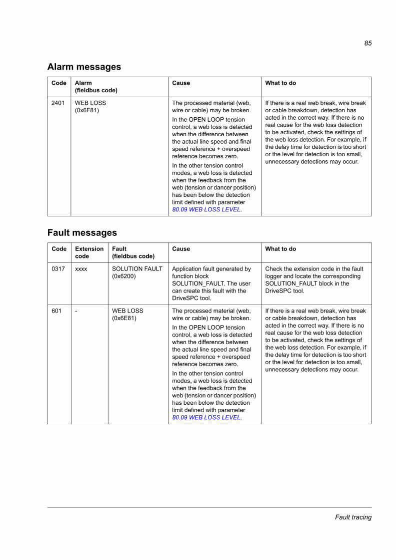
85
Alarm messages
Fault messages
Code Alarm(fieldbus code)
Cause What to do
2401 WEB LOSS(0x6F81)
The processed material (web, wire or cable) may be broken.In the OPEN LOOP tension control, a web loss is detected when the difference between the actual line speed and final speed reference + overspeed reference becomes zero.In the other tension control modes, a web loss is detected when the feedback from the web (tension or dancer position) has been below the detection limit defined with parameter 80.09 WEB LOSS LEVEL.
If there is a real web break, wire break or cable breakdown, detection has acted in the correct way. If there is no real cause for the web loss detection to be activated, check the settings of the web loss detection. For example, if the delay time for detection is too short or the level for detection is too small, unnecessary detections may occur.
Code Extension code
Fault(fieldbus code)
Cause What to do
0317 xxxx SOLUTION FAULT(0x6200)
Application fault generated by function block SOLUTION_FAULT. The user can create this fault with the DriveSPC tool.
Check the extension code in the fault logger and locate the corresponding SOLUTION_FAULT block in the DriveSPC tool.
601 - WEB LOSS(0x6E81)
The processed material (web, wire or cable) may be broken.In the OPEN LOOP tension control, a web loss is detected when the difference between the actual line speed and final speed reference + overspeed reference becomes zero.In the other tension control modes, a web loss is detected when the feedback from the web (tension or dancer position) has been below the detection limit defined with parameter 80.09 WEB LOSS LEVEL.
If there is a real web break, wire break or cable breakdown, detection has acted in the correct way. If there is no real cause for the web loss detection to be activated, check the settings of the web loss detection. For example, if the delay time for detection is too short or the level for detection is too small, unnecessary detections may occur.
Fault tracing

86
Fault tracing

87
Control block diagrams
What this chapter containsThis chapter presents the application program pages containing the winder control program technology blocks and custom circuits. Winder-specific blocks and circuits are white, while the firmware blocks are shaded in the following diagrams.
Control block diagrams

88
�����������
�
�����
��
� �
���
���
���
�����
���
�
����
���
����
��
���
���
���
�
���!
���
���
���
��
����
�"����
���#
��$%"
&��'
�
���
���
�����
�����
�
���!
������%�
���
�
����
����(�
���
(��)
����
&"��
��
��%��
����"
*��
���
"����
��"����
�
��#
��������"
����
�
���
���
"�$���
�
�+,
��-,.+
/��*
��0�1+
2-3-/-24/
5 /6
��!�
�-7�
8+7 &-37+74��
6�95
76���
�2+.
:+7:&-37+74��6���
��95
76���
� �;.0
/0,4&-37+74��
6��
��95
76���
(+� :0.
�<�20�
7
�<�2��
0���
0��+2
�7 1
+7 :
�11705 :
�70= �2.+�
�-2/
�0��:
��
� �1�:
12�
�0���
0�
Control block diagrams
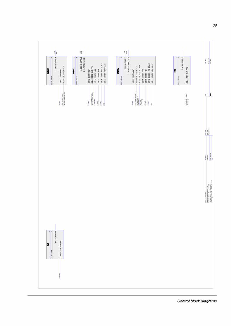
89
��
��
�"��
�&
�� �
���
��������%�
���
��)
>��
���
�?
���
����
���
�
�
��
�"��
�&
�� �
��
@���
�"�"����
�>(�
�)��"
����
���?
� A���!���
��
�"���
���
����
�
�"��
�&
�� �
���
�
�����"
��"
��
>"<21<
2?
@���
��"
�"����
�>��
����*"��
�?
� A������
�����
&���
���
��"
���
���
���
(-2�
����
��
�"��
�&
�� �
� �
�
����"
�"
��
>"<21<
2?
@���!
��"
"����
�>��
����*"��
��?
� A�����"��&
����'�
�
�� ��"
���B
>��
��CD?
�
��!��"
����
>�CD?
�
�����"
���B
���
&�>�!
��?
�
��#��"
�������
&�>�?
���
��"
���
���
���
(-2�
���
��"
��
����
����
�
�"��
�&
�� �
�!�
�
�����"
��"
��
>"<21<
2?
@����
��"
�"����
�>��
����*"��
����?
� A�������
�&�
�
@���#
��"
��"����
�>��
������
?�#A�����
�
�����"
����B
>��
��CD?
�
��E��"
�����
>�CD?
�
�����"
����B
���
&�>�!
��?
�
�����"
��������
&�>�?
���
��"
���
���
���
(-2
���
��"
���
��"��
�+,
�-,-2+
/�A"
�*��0�1+
2-3-/-24/
5 /6
��!�
�-7�
8+7 &-37+74��
6�95
76���
�2+.
:+7:&-37+74��6���
��95
76���
� �;.0
/0,4&-37+74��
6��
��95
76���
(+� :0.
�<�20�
7
�<�2��
0���
0��+2
�7 1
+7 :
�11705 :
�70= �2.+�
�-2/
�0��:
��
� �1�:
12�
�0���
0�
Control block diagrams
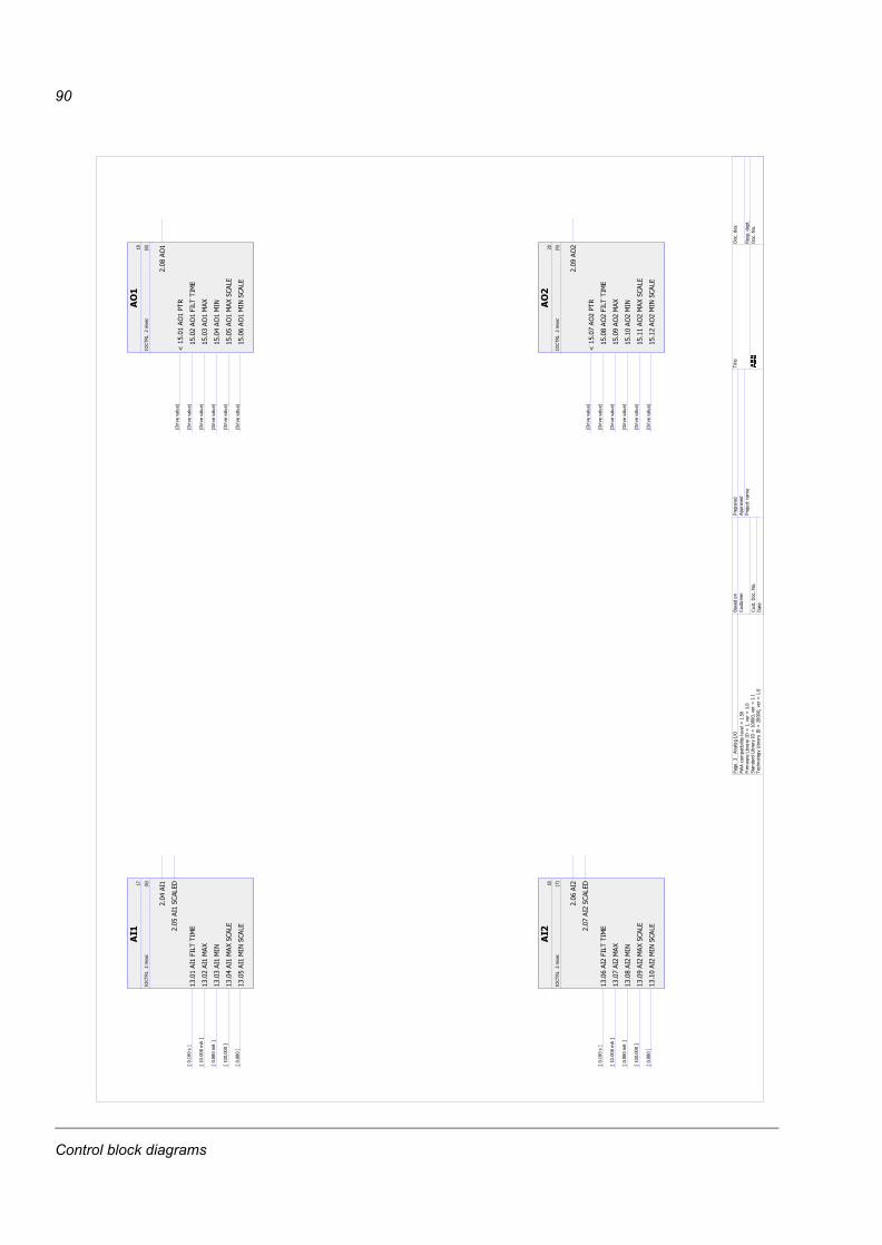
90
���
�#
�"��
�&
�� �
���
����������&�
���
�>����
��?
���������B
>��
����
��?
�����������
>����
���?
���� �����B��
�&�
>��
����
�?
����!���������
&�>����
�?
��
���
��!
������
&��
���
��
�"��
�&
�� �
�#�
���������&�
���
�>����
��?
����#����B
>��
����
��?
����������
>����
���?
����E����B��
�&�
>��
����
�?
�������������
&�>����
�?
���
��
��#
�����
&��
���
�E
�"��
�&
�� �
���
@�!���
�"���
���
7-5 5+/< �
�!
���"���&�
���
���
7-5 5+/< �
�!
����"���B
��7-5
5+/< �
�!
�� �"����
��7-5
5+/< �
�!
��!�"���B
���
&���
7-5 5+/< �
�!
����"�������
&���
7-5 5+/< �
���
�"�
���
�
�"��
�&
�� �
�E�
@�!��#
�"��
���
7-5 5+/< �
�!
����"��&�
���
���
7-5 5+/< �
�!
��E�"��B
��7-5
5+/< �
�!
����"���
��7-5
5+/< �
�!
����"��B
���
&���
7-5 5+/< �
�!
���"������
&���
7-5 5+/< �
��E
�"
�+,
��.+
/0,�A"
�*��0�1+
2-3-/-24/
5 /6
��!�
�-7�
8+7 &-37+74��
6�95
76���
�2+.
:+7:&-37+74��6���
��95
76���
� �;.0
/0,4&-37+74��
6��
��95
76���
(+� :0.
�<�20�
7
�<�2��
0���
0��+2
�7 1
+7 :
�11705 :
�70= �2.+�
�-2/
�0��:
��
� �1�:
12�
�0���
0�
Control block diagrams
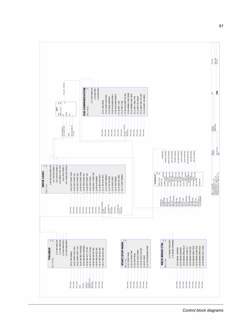
91
������
��
�����!
!��
F� �
���
!�
����(
���
�(&�
��7-5
5+/< �
!�
���"
��&"��
����
��7-5
5+/< �
!�
����"
��&"��
�"��
��7-5
5+/< �
!�
�� �(
���
���
"���
�&�1
:
!�
��!�(
���
��
"���
�&�+8
:+2+
@!����
�(�
���
���
���
����
����
�#A�����
@!���#
�(�
���
��
���
���������
��#�
��A�#�
@!����
�(�
�*(�
���
��7-5
5+/< �
@!���E
�(�
�*(��
���
��7-5
5+/< �
@!����
�(�
�*(�
���
��7-5
5+/< �
@!����
�(�
�*(�!
���
��7-5
5+/< �
��
�(�
�����*
���
�(�
�����*
��
�(�
�������
�
��!
�(�
�������
����������������� �
�����!
!��
F� �
��
!#
���&��)�"��
��7-5
5+/< �
!#
���"
��&"��
����
��7-5
5+/< �
!#
����"����
���
����7-5
5+/< �
!#
�� �"
&&"*��
���
)�
��7-5
5+/< �
!#
��!�"
&&"*��
���
)
��7-5
5+/< �
@!#���
���
����
��7-5
5+/< �
@!#��#
���
���
��7-5
5+/< �
@!#���
�"&&"*��
�*���
�"&&�*G��"
���B
� A��
!#
��E)�
���&���
��"��
��7-5
5+/< �
!#
���)�
���&���
�"���
��7-5
5+/< �
!#
�����
����'
���
���7-5
5+/< �
!#
����
���
�'�"
��
��7-5
5+/< �
!#
�����B
�������'��
��7-5
5+/< �
!#
�� ��������'��
���7-5
5+/< �
��#
��
�����*
��E
��
����
��
��
���
����� ����� �
������
�
� �
��
�!
���(�
�)��"���
"&
��7-5
5+/< �
@�!��
(��)
���
)�"*&
��7-5
5+/< �
�!
���(�
�)�"��
���&��
��7-5
5+/< �
�!
�� (�
�)��&
"��
�&�
��7-5
5+/< �
�!
��!(�
�)��&
"��
���
��7-5
5+/< �
�!
���(�
�)�"��
��"��
��7-5
5+/< �
@�!��#
(��)
��&
"��
���
��7-5
5+/< �
@�!���
(��)
�"��
�C"&�
��7-5
5+/< �
�!
��E(�
�)���
�&�
����
��7-5
5+/< �
���
(��)
��"
�����
���!
(��)
��"
����
�
� ��������
�!
������
�
� �
���
��
����B
�����
������
��7-5
5+/< �
@����
�B�
���
���
���
��7-5
5+/< �
@�����
�B�
���
���
��
��7-5
5+/< �
��
�� �B
����
������
��7-5
5+/< �
@����!
�B�
��
���
���
��7-5
5+/< �
@�����
�B�
��
���
��
��7-5
5+/< �
@����#
H"'���
���
��7-5
5+/< �
@�����
���
&����
����&
��7-5
5+/< �
@����E
������(&�
��7-5
5+/< �
@�����
����"
�"���
��7-5
5+/< �
@�����
����"
�"���
��"��
����"���E���
� A�E�
��
����
���
��C�(��
��7-5
5+/< �
@�����
�(�*
���
�>�(
������*?
� A���
@����
H"'��
���
��7-5
5+/< �
@����!
H"'���(
&���7-5
5+/< �
@�����
��
�*���
�>��
�����*?
� A��#�
@����#
���
�����(
&���7-5
5+/< �
���
��
�"&&"*��
�*
����
���
���*"��
�
���
���
���*"��
����
���
�����
&��
��
���!
&��
��*
"��
�
���#
�"��
&��
���
���
�� ���������
��
������
�
� �
� �
�������
���
�"��
��7-5
5+/< �
��������'
����
���7-5
5+/< �
�������
"��"��
��7-5
5+/< �
���� ��C"&�
���
����7-5
5+/< �
����!��C"&�
������
��7-5
5+/< �
�������C"&�
��7-5
5+/< �
����#��
�"�C
����'�"��
��7-5
5+/< �
(���
�����
�
���
�������
���
����
���
�*"����
� A������
"���
��
(���
��
(��
��&��
���
�"&&"*��
�*
� A����
"�"
&&�*G��"
���B
*�����
�*I �
E
���
�����
���
*�����
�*�
*�����
�*�
��!A���� �
*�����'��
"��
*�����'�
"��
���A #�
��"��
����
�"�
��"��
����"�
��!A ��
�"���
"��
&""�
"���&""��"
���
���A����
�����"����
�����
����"
����
���#A���
��������
���
��������
���
���A�!�
������
�����
�������
�����
����A���
�"�����
���
�"�����
���
���A���
�"����"*����
�"����"*����
���A���
����
������&�
�"��
���
���
�&�
��EA� ��
�"��
���
���
�"��
���
���
��EA� �
��'
���
&��
���'
���
&��
����A���
H"''��'���
�����
�*"���!
� A����H"
''��'�
��*���
��*�����E�
��"��
����"�
��"��
����"���E�
�"���
"��
&""�
�"���
"��
&""���E�
�����"����
������"����
���E�
��������
���
��������
�����E�
������
�����
�������
�����
���E�
�"�����
���
�"�����
�����E�
�"��������
�"����������E�
����
������&�
����
������&���E�
����
�����
����
�������E�
��'
���
&��
���'
���
&��
���E�
�+,
�7-5
&0,-�
�*��0�
1+2-3
-/-24/
5 /6
��!�
�-7�
8+7 &-37+74��
6�95 76���
�2+.
:+7:&-37+74��6�����
95 76���
� �;.0/0,4&-37+74��6
����
95 76���
(+� :0.
�<�20�
7
�<�2��0���0�
�+2
�7 1+7 :
�11705 :
�70= �2.+�
�-2/
�0��: ��
� �1�: 12�
�0���0�
Control block diagrams
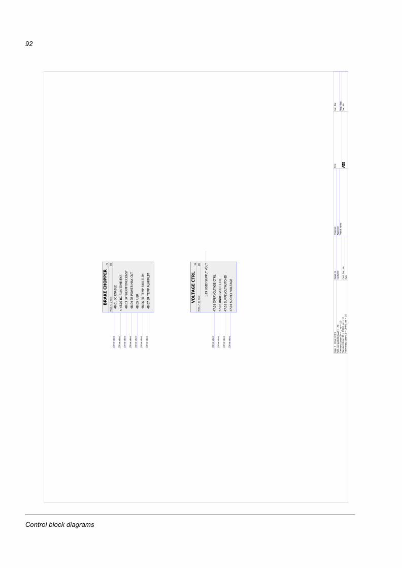
92
� ��������
E
�����
��
� �
���
�
���(�
���
(&�
��7-5
5+/< �
@ ���
(����
$���
���
���
7-5 5+/< �
�
���(�
�C��
������
"���
��7-5
5+/< �
�
�� (�
�"*����B
���
��7-5
5+/< �
�
��!�(�
��7-5
5+/< �
�
���(�
���
���
�&�
&��
��7-5
5+/< �
�
��#(�
���
��&
���
&��
��7-5
5+/< �
��������� �
�
�����
#���� �
���
#���"%�
�%"
&��'
���
�&��
7-5 5+/< �
#�����
��%"&�
���
&��
7-5 5+/< �
#�����
��&%
"&�
���"
$��
��7-5
5+/< �
#�� ��
��&�%"&��'
���
7-5 5+/< �
���E
���
�����
&�%"&�
�+,
!�7-5
�0
.270/
�*��0�1+
2-3-/-24/
5 /6
��!�
�-7�
8+7 &-37+74��
6�95
76���
�2+.
:+7:&-37+74��6���
��95
76���
� �;.0
/0,4&-37+74��
6��
��95
76���
(+� :0.
�<�20�
7
�<�2��
0���
0��+2
�7 1
+7 :
�11705 :
�70= �2.+�
�-2/
�0��:
��
� �1�:
12�
�0���
0�
Control block diagrams
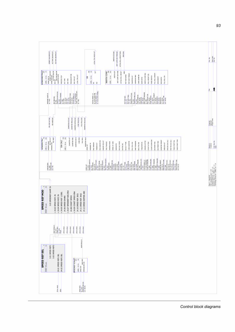
93
��� ���
�
����
��!��F� �
���
�������
�������&
��7-5 5+/< �
������
������&
J��"
�������
������
������
�����
��� �����
����
��!��F� �
� �
@ ������
��������
���
���
����#�
��A��#�
@ �� ���
�������
��������
��A����
@ ��!���
������A��&
��&��
�������
��C��
���7-5 5+/< �
@ ��#���
����
���'
���
��7-5 5+/< �
����"
���
�����
��7-5 5+/< �
@ ��E�"���
�����
���
��7-5 5+/< �
�������
����H"'�
��7-5 5+/< �
�������
����H"'
��7-5 5+/< �
������
��������(�
��7-5 5+/< �
�������
����
����
���
����
���
���
�&�I
��#
�����
�����
�!�
��������
���������
��A�����
�����K�"
�����
�����K�"
�����
���A����!�
���
���
����
���
����#�
"�
���
�����
�����
���
���
����
��*
"����E
� A�����&"
��&�(�
��
����
��*
"������
� A�����&"
��&��
��&�
"��
&"��
&��
�&�"����
�
*�����
����
"�I ��#
�����
�����
�#�
����������
�������
���
����
��A�����
�����������
��%��
���
%��
���E��
��AE��
������
�����
�"������
�����
�"�����
��A����
��"��
����"
���
"��
����"
���E�
� A�E�
�������
�������
��!A������
���
���
����
���
���!A�����
��"��
����
����
���
"��
�����
���
���!A������
�*H"
'��
���
����
*"���!
� A����H"
''��'�
&"��
&��
�&���
&"��
&��
�&�"����
���A����
����
������"
��
����
������"
�����#�
����
��������
���
����
������
����#�
���
��������
��
���
��������
�����#�
����
����"
�� ���
�����
�����
��!�
�"��"����
���"��"����
��#A##�
�"��"��"��
��
�"��"��"��
��#A#E�
������
�����
������
�����
�����
��A����
������
�����
�������
�����
������
��A����
�"��
������
���"
��������
�����A��� �
'��
���
��"
'��
���
��"
���A������
����
����"
����
�����
�"����
���E�
� A�E�
�"&&*
��'C
���
&�"
&&*
��'C
���
&��#A� ���
��B�
����
����
��B�
����
����
��#A� ����
��&&�"&&*
��'C�
��&&�"&&*
��'C�
��#A� �� �
*�(
���
����
*�(
���
����
��#A� ��!�
*�(
*���C
*�(
*���C
��#A� ����
��&&�"&&���
��&&�"&&���
���A���!�
����
�����
�����
�����
������
����
�"����
�����
����
�"����
����������
����
�&�"&&*
��'C
���
���&�"&&*
��'C
������
����
����
�����
*�����
���&
I E�
�����
���
��
*�����'�"��
��*
�����E�
� A�E�
*�����'���
*�����'���
���A E�
��%��
'"��
��%��
'"���E��
��%��
����
%��
���E��
�����&�
���
�����
���
���
��������
��������
�#A�����
�������
���
�������
���
����
��A�����
��B
���
��"�
��B
���
��"�
���A�����
�����"����
�����"����
��#�
��A�#�
��B
���
����"
���B
���
���
%�&
���A������
���
����"
���
����
����"
���#�
��A�#�
������
&�"��
������
&���)
��#�
��A�#�
*�����'�"��
��*
�����E�
� A�E�
��������"
����
���K�"
�����
���A����!�
'��
���
��"
'��
���
��"
���A������
�����&
��"��
�����&
��"��
���A�����
����()
���
����()
���
���A#��
��������
���
������
�����
���A�����
�"��
������
���"
��������
�����A��� �
��&&�"&&���
��&&�"&&���
���A���!�
*�(
�C��)
����
*�(
�C��)
����
���A�����
��'
���
&��
���
'���
&��
���E�
� A�E�
�"��
���
"�
�"��
���
"���
#�
�#A� #�
H"''
��'��
��%�
����
��*
"���!
� A����H"
''��'�
�"���
����
��"
���
����
���E�
� A�E�
�"���
�"*���
��"
���
�������E�
� A�E�
������
�����
������
�������E�
� A�E�
������
�����
�������
�����
���E�
� A�E�
������
�����
���
������
�����
���
���A�����
*�(
&"��
���
*�(
&"��
���
�� ��
�� A� ��
������
�����&
�������
�����&
����A����
������
�����&
�������
�����&
����A�����
�C��)��
�����&
�C��)��
�����&
���A��� �
�C��)��
�������
�C��)��
�������
���A���!�
������
�����
������
�����
�����
������
�����
�������
�����
������
������
�����
�"������
�����
�"�����
�"����
���"
�����
������
��&&�"&&
��&&�"&&�����
������
��C"&�
������
��C"&�
�����
�+,
��1
:� L
�*��0�1+2-3
-/-24/ 5 /6��!�
�-7�
8+7 &-37+74��6�95
76���
�2+.
:+7:&-37+74��6�����
95 76���
� �;.0
/0,4&-37+74��6����
95 76���
(+� :0.
�<�20�
7
�<�2��0���0�
�+2
�7 1
+7 :
�11705 :
�70= �2.
+�
�-2/
�0��:
��
� �1�:
12�
�0���
0�
Control block diagrams
94
��� �� ���
�����
�!�F� �
���
@!���
���
�����
���
����������"
�����#�
��A��#�
!����
������
&��'
�����K�"
���
�����A���
!�����
����
���
����
������
����#�
��A��#�
!�� ���
���
����
���
����������#�
��A��#�
!��!�C
���
���
���
��
��7-5 5+/< �
!����C
���
���
���
�
��7-5 5+/< �
!��#�C
���
���
����
���7-5 5+/< �
!����C
���
���
����
��7-5 5+/< �
!��E��
����
�H"
''��'
��7-5 5+/< �
!������
���
�H"
''��'
��7-5 5+/< �
!�����
��"
�����
��7-5 5+/< �
!����
�����
�(�
&��7-5 5+/< �
@!���
���
�����(�&
���
��7-5 5+/< �
���
���
����
���
���
�
��� �
�
�����
�!�F� �
��
@����
���
�����
���
�&��
������
�#A�����
@���
���
��������
�&��
�����
����
���
�#A��� �
���!��
������
���
����"�����E�
�#A��E�
������
������
�����
��7-5 5+/< �
���#��
���*
���"*
��7-5 5+/< �
������
��"�����
����
�����"�����
���
������
��A����
���E��
��"����
���
��7-5 5+/< �
������
���*
������
��7-5 5+/< �
������
���*
��C�
��7-5 5+/< �
�����
���*
��&"
��7-5 5+/< �
���!
���
����
����
�
����
���
�����
"���&�
���#
���
�"���"��
������� ��
#
�����
�!�F� �
� �
@����
���
�����
����
&��
������"���&�
�#A�����
�����
"�"
��'���
��7-5 5+/< �
��������
'��
��"����
���7-5 5+/< �
��� ���
�%��
�"����
���7-5 5+/< �
���!���
�%��&�����
��7-5 5+/< �
@����
���
�"���
���
��"�
�
���#��"
"���'���
���7-5 5+/< �
����(�
&��
����
���
��7-5 5+/< �
@���E
���
����
�&(�&
��
��7-5 5+/< �
��������"��
����
�&����
&�"
���
������
�#A���
������B
�"��
����
�&
����
&�"
���
�B����
�#A���
���������
���B
���
��7-5 5+/< �
����������
�������
��7-5 5+/< �
��� �'�������
�"��
��7-5 5+/< �
���!�������
���"��
��7-5 5+/< �
����
�"��
�������
�&
���������
!
�����
!�
F� �
��
�����
����(��
&��7-5 5+/< �
����
������
�����
��7-5 5+/< �
����"�"
�'��
���&
��7-5 5+/< �
�� �"�"
�'��
���%
��7-5 5+/< �
��!J�
�"���
��&��
����7-5 5+/< �
���J�
�"���
����&��
��7-5 5+/< �
��#�("
%����
��&��
��7-5 5+/< �
�����
��������
��'
����7-5 5+/< �
��E��
����(��
�&�
��7-5 5+/< �
����
���
�����
����
��I
��E
���
���
����
����
������
���
���
�������
����
���
�#A��� �
��%
��'
"��
��%
��'
"���E��
��AE��
������
&���)
������
&���)
��#�
��A�#�
������
�����
�"������
�����
�"�����
��A����
��'
"���������
��'
"����
�����
��#�
��A�#�
��������"
����
���K�"
�����
���A����!�
"%�
���
�����&
"%�
���������&
��!A���� �
"%�
���
������
"%�
����������
��!A����!�
�����
����&���
���������&��
���!A����
H"''��'���
����
��*"���!
� A����H"
''��'�
�������"��'
�������"��'
��EA����#�
&"��
&���
&���
&"��
&���
&�"�����
��A����
������"��
������"�����E�
���
�&�"
��&����
&I��
���
���
����
����
�"���
�"��&��
�"��
���
"��� #�
�#A� #�
��%
��'
"��
��%
��'
"���E��
��AE��
������
&���)
������
&���)
��#�
��A�#�
�"��
&��
��"
��&������
&��#�
��A�#�
�"��
&��
�"
�����
�� #�
�#A� #�
����
&�"
���
�B����
&�"
���
�B����
����
&�"
���
������
&�"
���
������
�"��
���
I � #
���
��
���
� �
�"��
������
��"
������"��
��A�����
������
&���)
������
&���)
��#�
��A�#�
������
���
�&�
����
�����
�&���E�
� A�E�
�"��
���
���
����
�������E�
� A�E�
�"��
(""��
�"��
(""��
��EA������
(""��
"���&��
(""��
"���&��
��EA���� �
�"��
���
"�
�"��
���
"��� #�
�"��
���
�"��
���
�� #�
�+, #�
1 :�27/
�*��0�
1+2-3-/-24/ 5 /6
��!�
�-7�
8+7 &-37+74��6�95 76���
�2+.:+
7:&-37+74��6�����
95 76���
� �;.0
/0,4&-37+74��6����
95 76���
(+� :0.
�<�20�
7
�<�2��
0���
0��+2
�7 1+7 :
�11705 :
�70= �2.
+�
�-2/
�0��:
��
� �1�: 12�
�0���
0�
Control block diagrams
95
�� �� ���
�
������!�
�F� �
���
�����"
��������
&��7-5 5+/<
�
����"
����������&
��7-5 5+/<
�
���E�"������
���
�"������
����
�� �� �����
������!�
�F� �
��
@�����"�������
>�"
������?
��A���E�
��� �
�B��
���"�����
��7-5 5+/<
�
���!�
�������"�����
��7-5 5+/<
�
����&"���C���
��7-5 5+/<
�
���#�"�����
���
��7-5 5+/<
�
�����"�����
��"*�
��7-5 5+/<
�
�����"��������
���
�����"��������C
&��
���
����
&��
�
������
!
�F�
���
���
�"�������
���
��A����
��
�"����������#�
��A�#�
���
���
�"���"
��
�#A���#�
"��
�"��������
� ����� �
�
�����
!�F� �
���
@� ����B�
�A�B
���&
��7-5 5+/<
�
@� ���B�
��"���A�
�&��7-5 5+/<
�
� ����B�
���
�&�
"���
��7-5 5+/<
�
� �� �B�
���
�&�
"��
��7-5 5+/<
�
� ��!�B�
��
�&�
"���
��7-5 5+/<
�
� ��#&"��&���
&�"��
��7-5 5+/<
�
@� �������
���
�����
�"����������
&�#A�����
@� ��E����
�"�����
�"��������C
&��
��A�����
@� ����"�����������
�"��������
��A��
�
�����"������"��
���
"��"����
)
���������
& �#
���
���
���
��E�
�"����
��
�"����
������
���A���
�
���������'
�����
�*"��
�
� A�������������'�
����
�����(
&���
�&&���
�%��E�
���AE��
������
�����
�������
�����
����
����A���
�
��'
���
&��
���'
���
&��
���
E�� A�E
�
������
&�"��
�����"����
&�"��
���A��
���
����
��"��
����
��"��
���A��
����
"��
�&"
"��"
���
�"���"��
&""���
E�� A�E
�
����
���
'�
����
���
'�
���A��
��!�
�"��'���
�"��'����E��
��AE��
��&&�"&&'���
��&&�"&&'����E��
��AE��
����'
���
�"����
���'
������
��E�
���AE��
��'
���
���
��'
���
�E��
��AE��
��'
�()
���
����()
���
���A�
��
��B��
���"�
��B��
���"�
���A��
���
��B������
%�&
��B������
%�&
���A��
����
������
�"��
���
������
���
"��
���
���A��
�� �
��B��
���
��B��
���
���A��
��!�
������
&���)
������
&���)��
#�
�����"����
�����"����
��#
�
������
�"�
������
�"���
#�
��'
���
���
����
��'
���
���
����
��#
�
��'
"��
��'
"����#
�
��'
"������
���
��'
"������
���
��#
�
��'
���"�
��'
���"���#
�
������"��"��
E
���
���
���
�����
����
����
����
����
�#A�����
����
����"��
����
�K�"�����
���A��
��!�
������������"�
������������"�
��EA�!
����
��
����������"�K�
��EA�!
���
��
����������"�K �
��EA�!
����
���
����������"�K��
��EA�!
�� �
���
����������"�K��
��EA�!
��!�
���
�����������"�K��
���EA�!
����
������"��"��
������"��"���E
�
���"
���
�"��E�
����
"��I �#
���
���
���
����
�"��"��"��
�"��"��"��
��#A#E
�
��%
��'
"��
��%
��'
"���E�
���AE��
������
&���)
������
&���)��
#���A�#
�
������
�����
������
��������
����A���
�
��'
�������
���
��'
���
���
����
��#
���A�#
�
*�����'�
"��
��*��
���E
�� A�E
�
��'
"����
�����
��'
"������
���
��#
���A�#
�
������"��"��
������"��"���E
���AE�
'��
����
�"'��
����
�"���A��
����
��B��
���"�
��B��
���"�
���A��
���
�"��&�����
�&�"
��&�����
�&��#�
�"��������
�"����������#�
*�����
���&
&I E�
���
��
��
����
����
���
����
���
����
����"�����
#���A��#
�
����
����"��
����
�K�"�����
���A��
��!�
���&&���
���&&���
���A��
��
�"��'���
�"��'���
���A��
��#�
��&&�"&&'���
��&&�"&&'���
���A��
����
�"����'
�����
����'
���
�"����
����A��
��E�
��'
�&�
�"����
��'
���
���
���A�
��
��'
���&
&���
��'
���&
&���
���A��
����
���&&���
����
�&&���
�����A��
��#�
���&&��
''���
���&&��'
'���
���A��
����
���&�
�'�����
���&&������
����A��
��E�
���&&���
�%�
���&&���
�%��E�
�
��'
���
��'
���
�E��
�"��'���
�"��'����E��
��&&�"&&'���
��&&�"&&'����E��
��'
������
���'
������
��E�
�
�+, ��0
7M<
� L
�*��0�1+2-3-/-24/ 5 /6
��!�
�-7�
8+7 &-37+74��6
�95 76���
�2+.:+7:&-37+74��6���
��95 76���
� �;.0
/0,4
&-37+74��6��
��95 76���
(+� :0.
�<�20� 7
�<�2��0���0�
�+2
�7 1
+7 :
�11
705 :
�70= �2.+�
�-2/
�0��:
��
� �1�: 1
2��0���0�
Control block diagrams
96
����
E
�����
!�
F� �
���
E����
���"���
���&
��7-5
5+/< �
E���
���"���
��&
��7-5
5+/< �
E����
���&�"����
&��
7-5 5+/< �
E���
��&��
C"��&
��7-5
5+/< �
E���!
�����(
&����&�
��7-5
5+/< �
E����
���������
���
C��
7-5 5+/< �
E���
���&��
&����
��7-5
5+/< �
@E��
���&�"
����
��7-5
5+/< �
����
���"���
����
��
���E
���"���
��"�
����
���"���
���
��
����
���"���
�"�
���
���
����
���
�
������������
�
�����
#���� �
��
E���������"
������
��7-5
5+/< �
E����(�
�������
��
��7-5
5+/< �
E������%
�"���(���
��7-5
5+/< �
E��� �"
����
�(���
��7-5
5+/< �
E���!���
���
)���
��7-5
5+/< �
E����C����
������
����
��7-5
5+/< �
E����C����
�(��
����
���
7-5 5+/< �
E���C����
��"������
��7-5
5+/< �
E�����
��&"
�)��
�&��
��7-5
5+/< �
E�����
��"
����"���(
��7-5
5+/< �
E����
���%
"&��(
��7-5
5+/< �
E�����
����
��"����
��7-5
5+/< �
E�� ��
�(�
������
��7-5
5+/< �
E��!��
��"��
��7-5
5+/< �
E�����
���
����
�����
��7-5
5+/< �
E��#��
�J�
�"�C��
���
7-5 5+/< �
E������
���
�"��
��7-5
5+/< �
E������
���
��B��&
���
7-5 5+/< �
��� �����
��
�����
#���� �
���
E������
"&%
�"&�
�����
��7-5
5+/< �
E���B
���'��&
���&
��7-5
5+/< �
E����B
���'��&
���
���
7-5 5+/< �
�����������
��
�����
#���� �
� �
E������
����
&����
��7-5
5+/< �
E�����
����
����
7-5 5+/< �
E������
����
��&�
�"��
��7-5
5+/< �
E��� ��
���"
���
����
��7-5
5+/< �
E���!��
����
���
���
��7-5
5+/< �
E������
��"��
&��
��7-5
5+/< �
E������
���
&����
��7-5
5+/< �
E�����
���
����
7-5 5+/< �
E������
���
��&�
�"��
��7-5
5+/< �
E��� ��
��"
���
����
��7-5
5+/< �
E���!��
���
���
���
��7-5
5+/< �
E������
�"��
&��
��7-5
5+/< �
�+,
��
.�0:
7�*
��0�1+
2-3-/-24/
5 /6
��!�
�-7�
8+7 &-37+74��
6�95
76���
�2+.
:+7:&-37+74��6���
��95
76���
� �;.0
/0,4&-37+74��
6��
��95
76���
(+� :0.
�<�20�
7
�<�2��
0���
0��+2
�7 1
+7 :
�11705 :
�70= �2.+�
�-2/
�0��:
��
� �1�:
12�
�0���
0�
Control block diagrams
97
���� ����� ��
!
�����
��
� �
���
�����&�B���
�&�B��
����
!����A��
!�
�����
���
��7-5
5+/< �
�����&��'���
��7-5
5+/< �
��� %"&�
�'����
��%�
��7-5
5+/< �
���!�&�B"��
��7-5
5+/< �
�����"
���
"��
�&""�
��7-5
5+/< �
���#���"���
���
��"
���
7-5 5+/< �
����
�&�
B���
���
�
���#
�"�������
���
�
�&�B���
&I��
!
���
�������
�� �
�&�B��
�A��B
�&�B��
�A��B
��EA �
�#��
�&�B��
�
�&�B��
�
��EA �
�#�
�&�B���
�&�B���
��EA �
�#��
���"��
�����
�"��
���
�"��
��A�����
����&�B��
�&��
��%�
�&�
B��
�&��EA��
�
�&�B��
����
���&�B��
����
����EA �
�# �
�&�B��
��&�B��
����
!�
�+,
���
0207�27/
�*��0�1+
2-3-/-24/
5 /6
��!�
�-7�
8+7 &-37+74��
6�95
76���
�2+.
:+7:&-37+74��6���
��95
76���
� �;.0
/0,4&-37+74��
6��
��95
76���
(+� :0.
�<�20�
7
�<�2��
0���
0��+2
�7 1
+7 :
�11705 :
�70= �2.+�
�-2/
�0��:
��
� �1�:
12�
�0���
0�
Control block diagrams
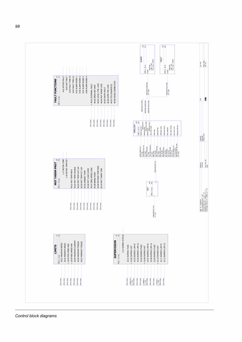
98
�����
�
�����
��
� �
�!�
����
��B�������
����
7-5 5+/< �
���
�����
�����
����
7-5 5+/< �
@����
�"����
�����
��7-5
5+/< �
@���
��'
���
�����
��7-5
5+/< �
���!
��B����������
���
7-5 5+/< �
����
��B�����"����
��7-5
5+/< �
���#
�����
���"����
��7-5
5+/< �
��������������
#
�����
��
� �
�#�
@ ����
�B��
���&��
�&�
��7-5
5+/< �
���
���
�����
����
��7-5
5+/< �
����
&"��
&���
&&"
����
7-5 5+/< �
���
�"��C
���
&"��
��7-5
5+/< �
���!
����C
���&�
��7-5
5+/< �
����
����
&�C
�&"��
��7-5
5+/< �
���#
��"���'�"����
��7-5
5+/< �
����
��"��
�"�����
�"�
��7-5
5+/< �
����
���
�%���
�&�
���
&���
���
&�
����
���
&����
�C�
���
���
&����
�&"
���!
�&�
��*
"���
����
�&�
��*
"��
���#
�&�
��*
"���
����
�&�
��*
"��
������ ��� ��
�
�����
#���� �
�!�
!����"���
����
"�
��7-5
5+/< �
!���"���
���"
����
��7-5
5+/< �
!����"���
���&�
&��
��7-5
5+/< �
!�� �"���
���&�&��
��7-5
5+/< �
!��!��(���
���
��
��7-5
5+/< �
!����"�&"
�����%�
��7-5
5+/< �
!��#J�
�"���
��&"��
��7-5
5+/< �
!���(���
)�"���
��7-5
5+/< �
!��E�"��
"���������
��7-5
5+/< �
!����"��C
������
���
7-5 5+/< �
���#
�"�"
����
�
����
�"�"
����
����
�� �����
�!
�����
#���� �
���
�����
����
�%���
��
��7-5
5+/< �
@����
����
�%����
>��
������
?�#A�����
�����
����
�%�&��C�
��7-5
5+/< �
����
����
�%�&��&"
��7-5
5+/< �
����!
����
�%��
��
��7-5
5+/< �
@�����
����
�%���
>��
����
�?
��A��� �
����#
����
�%&��C�
��7-5
5+/< �
�����
����
�%&��&"
��7-5
5+/< �
����E
����
�%���
��
��7-5
5+/< �
@�����
����
�%����
>�"
����?
��A�����
�����
����
�%�&��C�
��7-5
5+/< �
����
����
�%�&��&"
��7-5
5+/< �
���
����
�%����
��
�"�
�E�
���
�����
�!�
��"
���
��"��� #
��#A� #
�"
�"��
���
�"����
*�(
&"��
I� �
���
�����
���
����
����
��&�
����
����
"���&�
�#A�����
*�(
&"��
���
�"��
���
�"����
�� A�E
��
����
��"��
����
��"�����
E��#A��E
�
������
&���)
������
&���)
��#
���A�#
�
*�(
&"��
*�(
&"��
��!A��
��#�
*�(
&"��
�()
*�(
&"��
�()
���
��!A��
E�
*�(
&"��
&�%
�&*�(
&"��
&�%
�&��!A��
��E�
*�(
&"��
��&��
*�(
&"��
��&��
��!A��
����
��B
���
��"�
��B
���
��"�
���A��
���
��B
���
���%
�&��B
���
���%
�&���A��
����
��%
���&
���
���
���
�*"��
����
� A�������
�&�
�
*�(
&"��
�()
�"
*�(
&"��
�()
���
���
��!AE
�
*�(
&"��
���
*�(
&"��
���
�� �
�
*�(
&"��
�&���
*�(
&"��
�&�
���� �
�
*�(
&"�����
&�*�(
&"��
���
&��� �
�
�&�
��
�
���
�����
�#�
*�(
&"��
�0:
6 �
��3
<��0:
6�N����
�.+3
/ *�(
&"��
�&�
���� �
��� A�
��
���&�
� !
���
�����
���
*�(
&"��
�0:
6���
�3<��0:
6�N���
�
�.+3
/ *�(
&"��
���
&��� �
��� A�
��
�+,
� �
702 �2-0.�
�*��0�1+
2-3-/-24/ 5
/6��!�
�-7�
8+7 &-37+74��6�95
76���
�2+.
:+7:&-37+74��6���
��95
76���
� �;.0
/0,4
&-37+74��6��
��95
76���
(+� :0.
�<�20�
7
�<�2��
0���
0��+2
�7 1
+7 :
�11705 :
�70= �2.+
�
�-2/
�0��:
��
� �1
�: 12�
�0���
0�
Control block diagrams
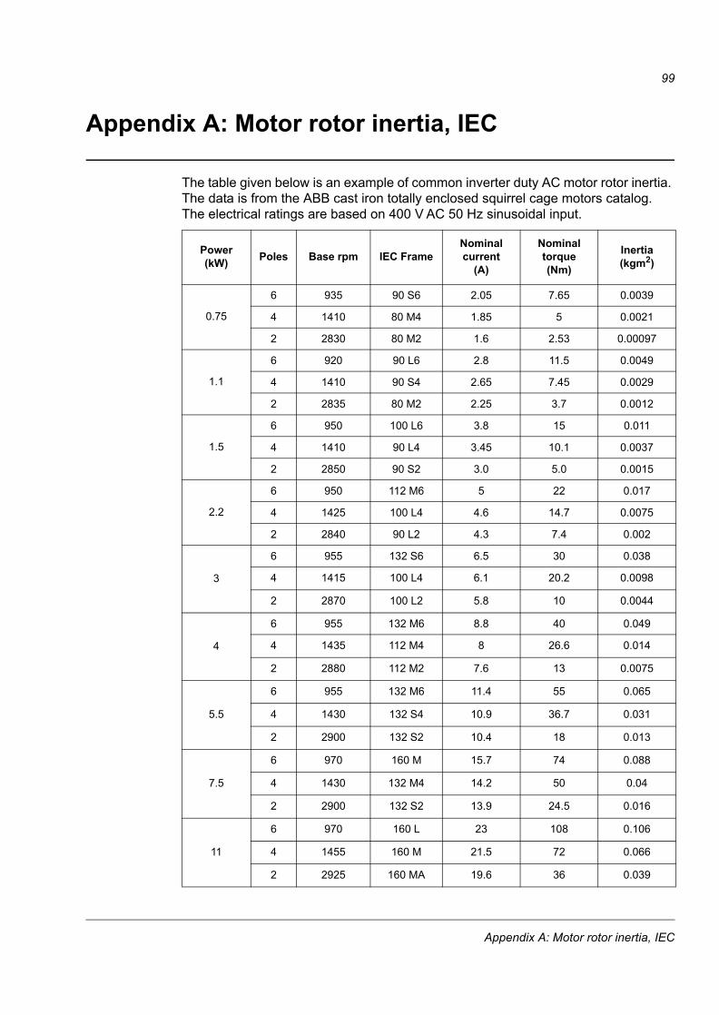
99
Appendix A: Motor rotor inertia, IEC
The table given below is an example of common inverter duty AC motor rotor inertia. The data is from the ABB cast iron totally enclosed squirrel cage motors catalog.The electrical ratings are based on 400 V AC 50 Hz sinusoidal input.
Power (kW) Poles Base rpm IEC Frame
Nominal current
(A)
Nominal torque(Nm)
Inertia(kgm2)
0.75
6 935 90 S6 2.05 7.65 0.0039
4 1410 80 M4 1.85 5 0.0021
2 2830 80 M2 1.6 2.53 0.00097
1.1
6 920 90 L6 2.8 11.5 0.0049
4 1410 90 S4 2.65 7.45 0.0029
2 2835 80 M2 2.25 3.7 0.0012
1.5
6 950 100 L6 3.8 15 0.011
4 1410 90 L4 3.45 10.1 0.0037
2 2850 90 S2 3.0 5.0 0.0015
2.2
6 950 112 M6 5 22 0.017
4 1425 100 L4 4.6 14.7 0.0075
2 2840 90 L2 4.3 7.4 0.002
3
6 955 132 S6 6.5 30 0.038
4 1415 100 L4 6.1 20.2 0.0098
2 2870 100 L2 5.8 10 0.0044
4
6 955 132 M6 8.8 40 0.049
4 1435 112 M4 8 26.6 0.014
2 2880 112 M2 7.6 13 0.0075
5.5
6 955 132 M6 11.4 55 0.065
4 1430 132 S4 10.9 36.7 0.031
2 2900 132 S2 10.4 18 0.013
7.5
6 970 160 M 15.7 74 0.088
4 1430 132 M4 14.2 50 0.04
2 2900 132 S2 13.9 24.5 0.016
11
6 970 160 L 23 108 0.106
4 1455 160 M 21.5 72 0.066
2 2925 160 MA 19.6 36 0.039
Appendix A: Motor rotor inertia, IEC
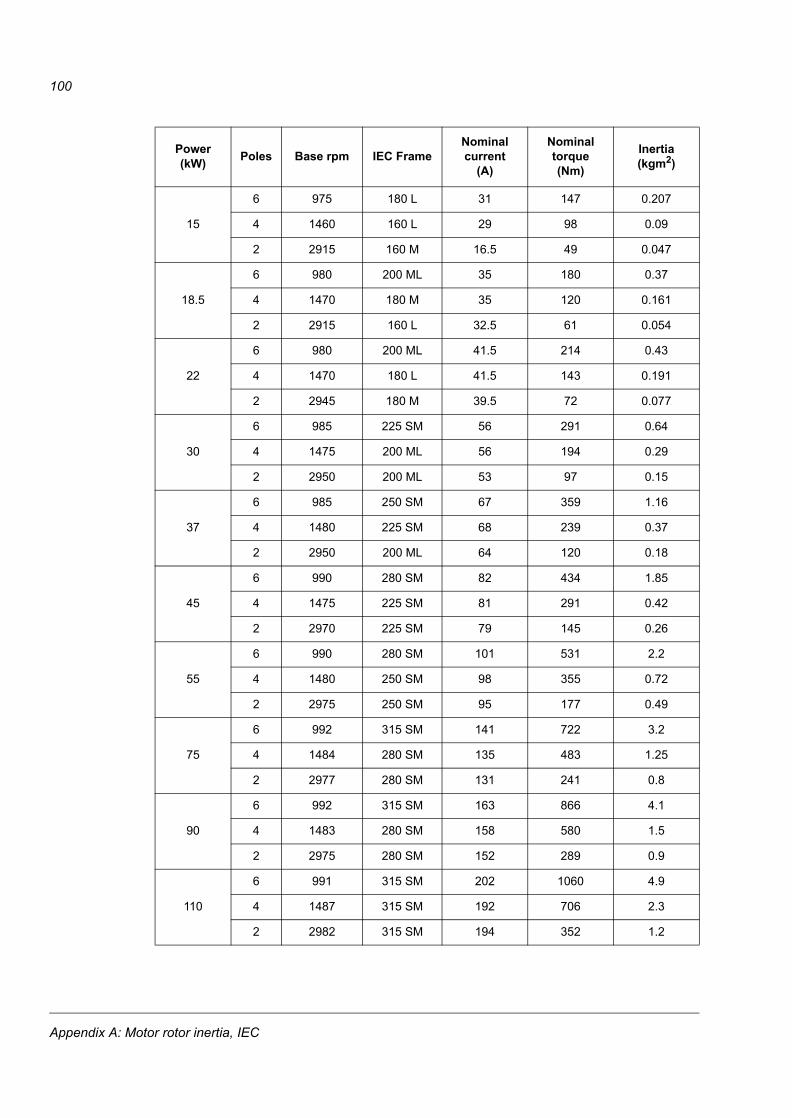
100
15
6 975 180 L 31 147 0.207
4 1460 160 L 29 98 0.09
2 2915 160 M 16.5 49 0.047
18.5
6 980 200 ML 35 180 0.37
4 1470 180 M 35 120 0.161
2 2915 160 L 32.5 61 0.054
22
6 980 200 ML 41.5 214 0.43
4 1470 180 L 41.5 143 0.191
2 2945 180 M 39.5 72 0.077
30
6 985 225 SM 56 291 0.64
4 1475 200 ML 56 194 0.29
2 2950 200 ML 53 97 0.15
37
6 985 250 SM 67 359 1.16
4 1480 225 SM 68 239 0.37
2 2950 200 ML 64 120 0.18
45
6 990 280 SM 82 434 1.85
4 1475 225 SM 81 291 0.42
2 2970 225 SM 79 145 0.26
55
6 990 280 SM 101 531 2.2
4 1480 250 SM 98 355 0.72
2 2975 250 SM 95 177 0.49
75
6 992 315 SM 141 722 3.2
4 1484 280 SM 135 483 1.25
2 2977 280 SM 131 241 0.8
90
6 992 315 SM 163 866 4.1
4 1483 280 SM 158 580 1.5
2 2975 280 SM 152 289 0.9
110
6 991 315 SM 202 1060 4.9
4 1487 315 SM 192 706 2.3
2 2982 315 SM 194 352 1.2
Power (kW) Poles Base rpm IEC Frame
Nominal current
(A)
Nominal torque(Nm)
Inertia(kgm2)
Appendix A: Motor rotor inertia, IEC
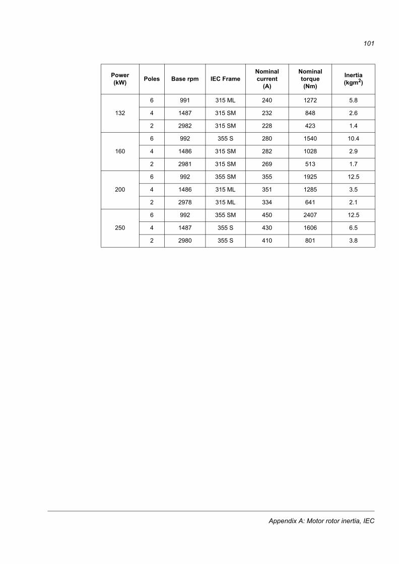
101
132
6 991 315 ML 240 1272 5.8
4 1487 315 SM 232 848 2.6
2 2982 315 SM 228 423 1.4
160
6 992 355 S 280 1540 10.4
4 1486 315 SM 282 1028 2.9
2 2981 315 SM 269 513 1.7
200
6 992 355 SM 355 1925 12.5
4 1486 315 ML 351 1285 3.5
2 2978 315 ML 334 641 2.1
250
6 992 355 SM 450 2407 12.5
4 1487 355 S 430 1606 6.5
2 2980 355 S 410 801 3.8
Power (kW) Poles Base rpm IEC Frame
Nominal current
(A)
Nominal torque(Nm)
Inertia(kgm2)
Appendix A: Motor rotor inertia, IEC

102
Appendix A: Motor rotor inertia, IEC


3AU
A00
0003
1510
Rev
C /
EN
EFF
EC
TIV
E: 2
010-
08-1
6
ABB OyDrivesP.O. Box 184FI-00381 HELSINKIFINLANDTelephone +358 10 22 11Fax +358 10 22 22681www.abb.com/drives
ABB Inc.Automation TechnologiesDrives & Motors16250 West Glendale DriveNew Berlin, WI 53151USATelephone 262 785-3200
1-800-HELP-365Fax 262 780-5135www.abb.com/drives
ABB Beijing Drive Systems Co. Ltd.No. 1, Block D, A-10 Jiuxianqiao BeiluChaoyang DistrictBeijing, P.R. China, 100015Telephone +86 10 5821 7788Fax +86 10 5821 7618www.abb.com/drives