Embed Size (px)
Citation preview

Chapter 1Date 11/04/99, page 1
EUROPEANFIELDBUS STANDARD
EN 50170P R O C E S S
M A N U F A C T U R I N G
B U
I L D
I N
G
PROFIBUS Workshop

Chapter 1Date 11/04/99, page 2
PROFIBUS
� Overview chapter 1� PROFIBUS EN 50170
� PTO
� Protocols FMS, DP, PA� reliability
� wiring
� DP-details chapter 2� GSD - file
� functions
� ASICs chapter 3� PIC and certification chapter 4

Chapter 1Date 11/04/99, page 3
PROFIBUS
� Why select a fieldbus system� independent of proprietary solution
� vendor independent
� cost savings
� increase of productivity in terms of� faster� more flexible� easy expandable� customized
Chapter 1Date 11/04/99, page 4
PROFIBUS
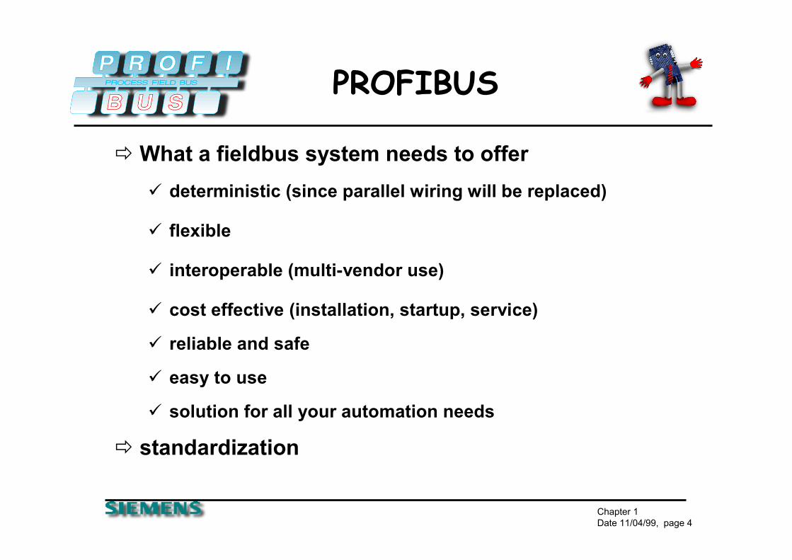
� What a fieldbus system needs to offer� deterministic (since parallel wiring will be replaced)
� flexible
� interoperable (multi-vendor use)
� cost effective (installation, startup, service)
� reliable and safe
� easy to use
� solution for all your automation needs
� standardization

Chapter 1Date 11/04/99, page 5
EN 50170 Volume 2
Process Automation
PROFIBUS-PAIEC 1158-2
- Powering over the bus - Intrinsic safety
Factory Automation
PROFIBUS-DPRS 485 / FO
- Plug and play- Efficient and cost effective
Fast
General PurposeAutomation
PROFIBUS-FMSRS 485 / FO
- Large variety of applications- Multi-master communication
Universal Application Oriented

Chapter 1Date 11/04/99, page 6
EN 50170
� The PROFIBUS Standard EN 50170 is complete, open, vendor- independent and validated
� The PROFIBUS Technology is in accordance with existing parts of the IEC Fieldbus Standard IEC 1158
� PROFIBUS is proven and has an installed base of > 3,000,000* devices that are in use all over the world
� The stable PROFIBUS Standard protects the investments of users and vendors world-wide
PROFIBUSEN 50170 *Status: Q3/1999

Chapter 1Date 11/04/99, page 7
INTERNATIONAL� More than 900 members - 23 regional user associations
ChinaJapanKoreaSingapore
South AfricaAustriaBelgiumCzech RepublicDenmarkFinlandFranceGermanyIrelandItalyNetherlandsNorwayRussiaSwedenSwitzerlandUnited Kingdom
AfricaAfricaAmericaAmerica EuropeEurope AsiaAsia
PROFIBUS InternationalPROFIBUS International
BrazilUSA
*Status: Q3/1999
AustraliaNew Zealand
AustraliaAustralia

Chapter 1Date 11/04/99, page 8
PRODUCT Variety
� Today there are more than 1,900* products from more than 280* different vendors available
or visit the Web - Site:http://www.profibus.com
on CD available from every user group world-wide
Get your free copy of the latest PROFIBUS product guide:
*Status: Q3/1999

Chapter 1Date 11/04/99, page 9
PRODUCT VarietyDrives
AC Drives
DC Drives
Decentralized I/OBinary I/O
Analog I/O
Regulators
Timer
Counter
Ident-Systems
GatewaysAS-Interface
Proprietary networks
ToolsConfiguration
Bus Monitor
Engineering
Host Interfaces VAX computers
VME computers
Network components Repeaters
Fiber optics
Cables
Controllers PLC/NC/RC
VME, PC
Workstation
Software Drivers DOS/Windows/NT/95
RT-OS/OS9/VRTX
VxWorks/PSOS+
OS2, QNX
UNIX/VMS
ServicesDevelopment Support
Implementation Support
TrainingMMI
Operator Panels
Text DisplaysValvesPneumatic Valves
Magnetic Valves
InstrumentsLevel
Flow
Pressure
Temperature

Chapter 1Date 11/04/99, page 10
CNCPC/VME
VME/PCPLC DCS
AreaController
Ethernet/TCP/IP TCP/IP/Ethernet
PROFIBUS-FMS
PROFIBUS-DP PROFIBUS-PA
Factory level
Bus CycleTime
< 1000 ms
Cell Level
Bus CycleTime
< 100 ms
Field Level
Bus Cycle-Time
< 10 ms

Chapter 1Date 11/04/99, page 11
EN 50170 - 2
� The PROFIBUS Protocol is in Accordance with the ISO/OSI Reference Model for Open Systems
PA-ProfilesFMS
DeviceProfiles
FMS
IEC 1158-2
User
Laye
r
(3)-(6)
Application(7)
Data Link(2)
Physical(1)
not used
PA
EN 50 170 PROFIBUS guidelines + profiles
DP
DP-Extensions
DP-Profiles
RS-485 / Fiber Optic
DP Basic Functions
Fieldbus Data Link (FDL) IEC Interface
Fieldbus MessageSpecification
(page 14 in the binder)

Chapter 1Date 11/04/99, page 12
Product Profiles
� PROFIBUS has defined profiles for the easy interconnectivity of certain product ranges� NC/RC Profile (3.052)
� Encoder Profile (3.062)
� Variable-Speed Drive Profile (3.071)
� Operator Control and Process Monitoring Profile (HMI)
� PA Profile
(page 12 in the binder)

Chapter 1Date 11/04/99, page 13
Bus Access
� The PROFIBUS Bus Access Method combines Multi-Master and Master-Slave communications
PROFIBUS
Active Stations, Master Devices
Passive Stations(Slave Devices) are polled
PLCPC

Chapter 1Date 11/04/99, page 14
Bus Access
� the PROFIBUS Bus Access Protocol (Layer 2) is identical for all three PROFIBUS variations
� this enables transparent communication and easy combinations of FMS/DP/PA Network sections
� Because FMS/DP use the same Physical Media (RS-485/FO), they can be combined on the same cable
Active Stations, Master Devices
PROFIBUS
PLCPLC PC

Chapter 1Date 11/04/99, page 15
Bus Access
� Hybrid Bus Access Protocol� Token-Passing between Masters
Master - Slave Protocol between Master and Slaves
� Master� active stations with the right to control the bus for a
limited amount of time (Token - Hold - Time)
� Slave� Slaves only respond on request of a Master -
they have no rights to control the bus

Chapter 1Date 11/04/99, page 16
Bus Access
� in Multi-Master Networks, the Token Passing procedure must ensure that each master has enough time to fulfill its communication tasks
� the user therefore configures the overall Target Token Rotation Time (TTR) taking into account the communication tasks of all masters
� each Master calculates the available amount of time for its communication tasks at token receipt according to the following rule:
TTH = Token Hold TimeTTR = Target Token Rotation TimeTRR = Real Token Rotation Time
TTH = TTR - TRR

Chapter 1Date 11/04/99, page 17
FMS, DP, PA
� FMS stands for Fieldbus Messaging System� peer to peer communication
� DP stands for Decentralized Periphery� fast data exchange
� PA stands for Process Automation� intrinsically safe environment

Chapter 1Date 11/04/99, page 18
FMS/DP In Common
FMSDeviceProfiles
IEC Interface*
FMS
User
Laye
r
(3)-(6)
Application(7)
Data Link(2)
Physical(1)
EN 50 170 PROFIBUS guidelines + profiles
DPDP-Profiles
RS-485 / Fiber Optic
Fieldbus data link (FDL)
DP Basic Functions
Fieldbus MessageSpecification

Chapter 1Date 11/04/99, page 19
FMS/DP In Common
� DP and FMS are based on Layer 1 and 2:� DP and FMS can be operated on the same bus
� Message header and data length are identical
� The bus physics are identical
� One master can service several slaves� Several masters can participate on the bus� Baudrates from 9.6 kBd up to 12 MBd are possible

Chapter 1Date 11/04/99, page 20
FMS/DP In Common
� Data transmission can be between 1 and 244 bytes� 126 stations can be connected� System can consist of several segments� 32 stations (RS 485 drivers) per segment� Common components
� Cabling, connectors, repeater, fibre optic
� Savings in maintenance and spare parts inventory

Chapter 1Date 11/04/99, page 21
PA/DP In Common
User
Laye
r
(3)-(6)
Application(7)
Data Link(2)
Physical(1)
EN 50 170 PROFIBUS guidelines + profiles
Specification (FMS)
PA-Profiles
IEC 1158-2
PADP
DP-Extensions
Fieldbus Data Link (FDL)
DP-Profiles
RS-485 / Fiber Optic
FDL
DP Basic Functions
IEC Interface*

Chapter 1Date 11/04/99, page 22
PA/DP In Common
� DP and PA are based on the same protocol definition - DP/V1 (extended DP)� DP and PA can use the same master systems
� Message header and data length are identical
� Configuration tools are the same
� Data transmission can be between 1 and 244 bytes

Chapter 1Date 11/04/99, page 23
PA/DP In Common
PROFIBUS-PA
PROFIBUS-DP, up to 12 Mbit/s
PLC or PC with PROFIBUS
DP-Slave
DP/AS-ilink
Actuator/Sensor interface
24 VDP/PA coupler,
DP/PA link
PA - 31.25 kBd

Chapter 1Date 11/04/99, page 24
FMS Features
� FMS is optimized for universal, object oriented communication of intelligent master devices at the cell level
� FMS permits a subset of the MMS-Functions (Manufacturing Message Specification, ISO 9506)
� A slave can be assigned to several masters� Several masters can write to the same slave
� Communication connections can be temporary or permanent
� Communication is defined in a communication relation list

Chapter 1Date 11/04/99, page 25
FMS Features
� Main application areas are: � Transmission of large amounts of data e.g..
programs, data blocks....
� Integration of several decentralized process parts to one common process
� Communication between intelligent stations

Chapter 1Date 11/04/99, page 26
FMS Features
� FMS access procedure
Slave 1 Slave 2 Slave 3 Slave x

Chapter 1Date 11/04/99, page 27
PA Features
� Based on the extended PROFIBUS-DP Protocol and IEC 1158-2 Transmission � Suitable to replace today's 4...20 mA Technology
� Only two wires for data and power
� Connects Instruments to the control system via a serial bus
� Functional improvements plus reliable serial digital transmission
� Control, regulation and monitoring via a simple twisted pair cable
� A single engineering tool for all devices

Chapter 1Date 11/04/99, page 28
PA Features
� Based on the extended PROFIBUS-DP Protocol and IEC 1158-2 Transmission� Interoperability and interchangeability due to the
PROFIBUS-PA Profile
� Maintenance and diagnostic information from the instruments available
� low power management and therefore suitable for EEx-Applications with Intrinsic Safety
� Distance up to 1900m per segment

Chapter 1Date 11/04/99, page 29
PA Features
Typical System Configuration with PROFIBUS-PA
PROFIBUS-DP RS 485 up to 12 MBit/s
Area Controller (PLC) Engineering or
B&B Tool
PROFIBUS-PA
IEC 1158-2 with 31,25 kBit/sI
εx
Segment-coupler/Link
Transmitter
H2
H1
+ εx

Chapter 1Date 11/04/99, page 30
DP Features
� DP communication is permanent and cyclic � the transmitted data is specified during the
configuration (optimized data exchange)� only one master can write outputs (safety aspect)� data can be read by controlling and Class 2 master� acyclic data via DPV1 functions� alarm acknowledgment� fastest fieldbus system (up to 12 MBaud)� up to 244 byte input AND 244 byte output data per
station

Chapter 1Date 11/04/99, page 31
DP Features
� DP- Access Procedure
Slave 1 Slave 2 Slave 3 Slave x
Master - Token exchange
Class 2

Chapter 1Date 11/04/99, page 32
Reliability-DP/FMS
� Hamming Distance HD = 4� HD 4 means, that up to 3 transmission failures at a
time can be detected (done by the ASICs)� By detecting a faulty telegram, it will be resent
automatically without affecting other existing stations
� HD 4 is a term used to describe the reliability of the data transmission on the Profibus network.� Special Start and End Sentinels� Parity Bit for Each Byte� Slip Free� According to IEC 870-5-1� Delimiter Synchronization

Chapter 1Date 11/04/99, page 33
Reliability-DP/FMS
� HD 4 enables the detection of the following errors:� Line Protocol Errors
� Framing Errors� Overrun Errors� Parity Errors
� Transmission Protocol Errors� Faulty Start Delimiter� Frame Check Bytes� End Delimiters� Invalid Frame Length� Invalid Response Times

Chapter 1Date 11/04/99, page 34
PROFIBUS Wiring
� PROFIBUS DP/FMS wiring can be done with:� twisted shielded pair copper cable
� fiber optic components
� infrared components
� detailed installation guideline is available PTO order no. 2.112

Chapter 1Date 11/04/99, page 35
PROFIBUS Wiring
� twisted shielded pair cable� line parameters are defined in EN 50170
� standard cable available from Belden and Siemens
� standard connectors availableBaudrate Max. Segment length Max. Expansion
9.6 1000m / 3278feet 10,000m / 32786feet19.2 1000m / 3278feet 10,000m / 32786feet
93.75 1000m / 3278feet 10,000m / 32786feet187.5 1000m / 3278feet 10,000m / 32786feet500.0 400m / 1311feet 4,000m / 13114feet
1,500.0 200m / 655feet 2,000m / 6557feet3,000.0 100m / 327feet 1,000m / 3270feet6,000.0 100m / 327feet 1,000m / 3270feet
12,000.0 100m / 327feet 1,000m / 3270feetmax. expansion is done with 9 repeaters in a row

Chapter 1Date 11/04/99, page 36
PROFIBUS Wiring
� Special requirements for baudrates >1.5 MBaud� use of Baudrates greater than 1.5 MBaud requires special
connectors. The connector or the device has to have built in Inductors in order to run with higher baudrates (as stated in the PROFIBUS guidelines)
� spur lines are not allowed when using baud rates greater than 1.5 MBaud
� in some applications, several bus connectors are used at electrically short distances; 12 MBaud installations require a minimum cable length between two stations of 1m/ 3feet

Chapter 1Date 11/04/99, page 37
PROFIBUS Wiring
� Cable Shielding� use only cables with braided shields.
� the shield density should be more than 80 %
� always connect the cable shields at both ends
� if a potential difference occurs between the grounding points, an equalization current can flow through a shield connected at both ends. In this case, install an additional potential equalization line

Chapter 1Date 11/04/99, page 38
PROFIBUS Wiring
� one preferred connector type - 9 pin Sub-D� connectors with integrated termination available� for use of higher baudrates, inductivity built in� easy plug and unplug without interrupting the
communication to other devices� other connector types are possible; mandatory signals
(A,B, GND, 5V) must be provided as well as a possibility for termination

Chapter 1Date 11/04/99, page 39
PROFIBUS Wiring
� 9 pin sub D
Chapter 1Date 11/04/99, page 40
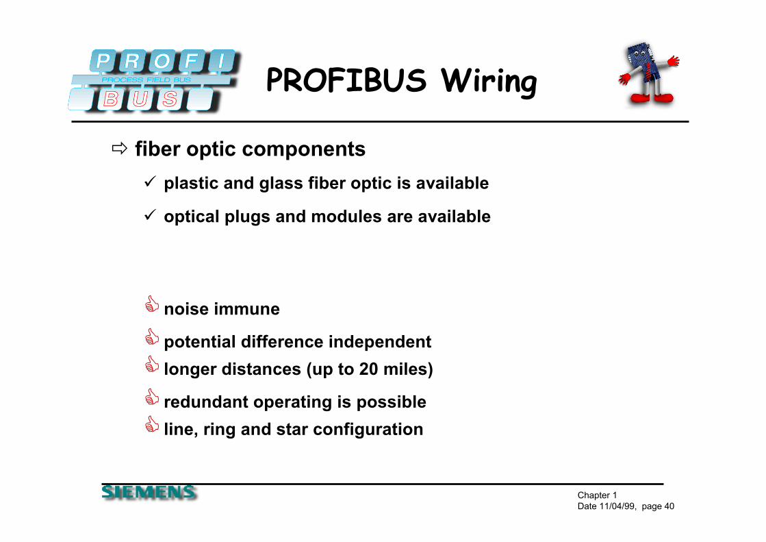
PROFIBUS Wiring
� fiber optic components� plastic and glass fiber optic is available
� optical plugs and modules are available
�noise immune
�potential difference independent� longer distances (up to 20 miles)
� redundant operating is possible� line, ring and star configuration
Chapter 1Date 11/04/99, page 41
PROFIBUS Wiring
� infrared components� wireless linking of devices in close-up ranges
� communication with moving devices
� communication with changing devices
� noise immune
� ground independent

Chapter 1Date 11/04/99, page 42
PROFIBUS Wiring
� PROFIBUS FMS / DP both based on RS 485� Termination is necessary
� Expansion of network through segments
� the two wire cable is usually color coded
!! recommendation:
use always the red wire for signal B (pin3 - TXD/RXD-positive)
and the green wire for signal A (pin 8 - TXD/RXD-negative)
� the shield is connected to housing
Chapter 1Date 11/04/99, page 43
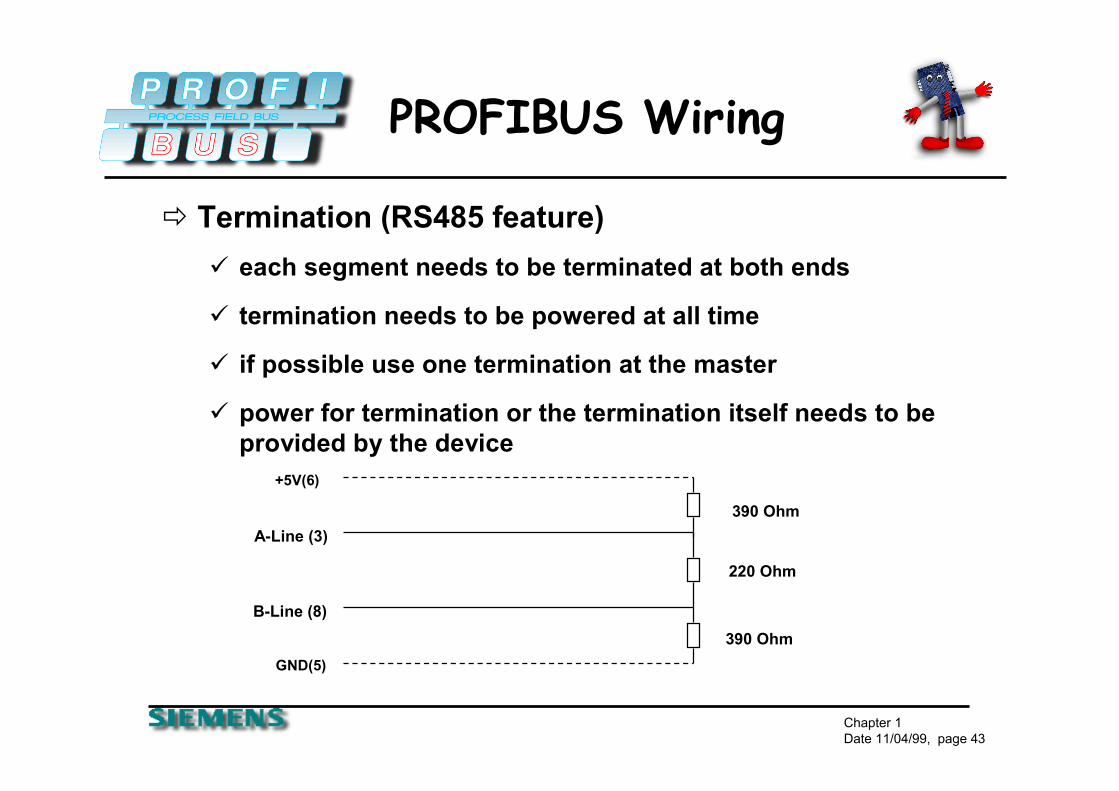
PROFIBUS Wiring
� Termination (RS485 feature)� each segment needs to be terminated at both ends
� termination needs to be powered at all time
� if possible use one termination at the master
� power for termination or the termination itself needs to be provided by the device
390 Ohm
A-Line (3)
B-Line (8)
220 Ohm
390 Ohm
GND(5)
+5V(6)

Chapter 1Date 11/04/99, page 44
PROFIBUS Wiring
� Segment structure with termination
Repeater or last device
...
Master
Termination “on” (usually whenever only one cable is connectedto a device the termination needs to be “on”)

Chapter 1Date 11/04/99, page 45
PROFIBUS Wiring
� Segments are needed for� exceeding the length
� exceeding 32 devices (incl. Repeater/OLM)
� Segments can be used for� building branch segments
� connecting up to 126 stations (no addr. for Repeater/ OLM)
� Rules� segment has a max. of 32 devices (incl. Repeater/OLM)
� the first and the last segment can have 31 stations
� segments between have 30 stations as a maximum

Chapter 1Date 11/04/99, page 46
PROFIBUS Wiring
� segment structure with termination
Connectsegments
...
RemoteRepeater
Link Segment(Segment withoutstations)
...Branch segments
...
Interface forfiber optic
Max. Number Repeater Cascading: 9 Termination “on”

Chapter 1Date 11/04/99, page 47
PROFIBUS Wiring
Several interfaces enableredundant systems
Fiber optic segmentsenable redundant wiring
Two devices per measuring point
FOcoupler
FOcoupler
FOcoupler
FOcoupler
System redundancy Media redundancy
� Redundancy Improves System Reliability

Chapter 1Date 11/04/99, page 48
COST Savings
� Cost Savings in Hardware and Assembly� Less hardware components (I/O, terminal blocks, barriers)
Easier, quicker and less expensive installation
� Cost Savings in Engineering� Easier configuration (only one tool for all devices)
Easier preventive maintenanceEasier and much faster system start-up
� Greater Manufacturing Flexibility� Improved functionality increases plant productivity
Improved availability and reduced down timeAccurate and reliable diagnostic dataReliable digital transmission technology

Chapter 1Date 11/04/99, page 49
COST Savings
Engineering
Assembly
Hardware
51%
23%
27%
22%
22%
12%
0%
50%
100%
Hardware Assembly Engineering
57%
Today (4...20mA) PROFIBUS


![PROFIBUS DP bus interface, PROFIBUS DP [BU 2700]...Sicherheit/PROFIBUS DP [BU 2700]/Bestimmungsgemäße Ver wendung PROFIBUS DP @ 8\mod_1461835577600_388.docx @ 2249429 @ 2 @ 1 2.1](https://img.pdfslide.us/doc/110x75/60b54c574bd00c04b50e633d/profibus-dp-bus-interface-profibus-dp-bu-2700-sicherheitprofibus-dp-bu.jpg)