Embed Size (px)
Citation preview

CompactRIO PROFIBUS DP-Getting Started- V2.4/25.09.2017
CompactRIO PROFIBUS DP
DP Master - Getting Started
V2.4/25.09.2017
d:\project\5362_crio-dp_master\anwenderdoku\master\version_2.4_vipm\gettingstarted_crio_pb_dp-master_e.doc
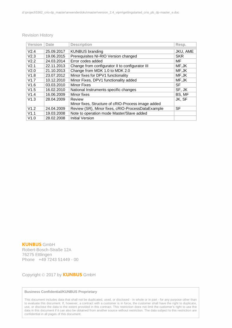
Revision History
Version Date Description Resp.
V2.4 25.09.2017 KUNBUS branding JKU, AME
V2.3 19.06.2015 Prerequisites NI-RIO Version changed SKR
V2.2 24.03.2014 Error codes added MF
V2.1 22.11.2013 Change from configurator II to configurator III MF,JK
V2.0 21.10.2013 Change from MDK 1.0 to MDK 2.0 MF,JK
V1.8 23.07.2012 Minor fixes for DPV1 functionality MF,JK
V1.7 10.12.2010 Minor Fixes, DPV1 functionality added MF,JK
V1.6 03.03.2010 Minor Fixes SF
V1.5 16.02.2010 National Instruments specific changes SF, JK
V1.4 16.06.2009 Minor fixes BS, MF
V1.3 28.04.2009 Review Minor fixes, Structure of cRIO-Process image added
JK, SF
V1.2 24.04.2009 Review (SR), Minor fixes, cRIO-ProcessDataExample SF
V1.1 19.03.2008 Note to operation mode Master/Slave added
V1.0 28.02.2008 Initial Version
GmbH Robert-Bosch-Straße 12A
76275 Ettlingen Phone +49 7243 51449 - 00
Copyright 2017 by GmbH
Business Confidential/KUNBUS Proprietary This document includes data that shall not be duplicated, used, or disclosed - in whole or in part - for any purpose other than
to evaluate this document. If, however, a contract with a customer is in force, the customer shall have the right to duplicate, use, or disclose the data to the extent provided in this contract. This restriction does not limit the customer’s right to use the data in this document if it can also be obtained from another source without restriction. The data subject to this restriction are
confidential in all pages of this document.
DP Master - Getting Started Contents
CompactRIO PROFIBUS DP-Getting Started-V2.4/25.09.2017 i Business Confidential/ Proprietary
Contents
1 Introduction ................................................................................................................... 1
1.1 Worldwide Support and Services ......................................................................... 1
1.2 Prerequisites: ....................................................................................................... 1
2 Installation .................................................................................................................... 3
3 PROFIBUS configuration .............................................................................................. 4
3.1 PROFIBUS-DP configuration download ............................................................... 5
3.2 Configurator III Monitor/Modify mode ................................................................... 7
4 FPGA Method and Property Nodes............................................................................... 8
4.1 Module Property Nodes ....................................................................................... 9 4.1.1 Init cRIO PB Property ............................................................................. 9
4.2 DP Master Methode Nodes .................................................................................. 9 4.2.1 Start/Stop DP Master Method ................................................................ 9 4.2.2 Read/Write Data Method ...................................................................... 10
4.2.2.1 Read/Write DP Slave I/O-Data ............................................... 10 4.2.2.2 Read/Write process data image ............................................. 10
4.2.3 Get Input Data Method ......................................................................... 11 4.2.4 Get Output Data Method ...................................................................... 11 4.2.5 Set Output Data Method ...................................................................... 12 4.2.6 Read Diagnostic Data Method ............................................................. 13 4.2.7 Get Diagnostic Data Method ................................................................ 13
4.2.7.1 Diagnostic data description..................................................... 14
4.3 DPV1 Master API............................................................................................... 16 4.3.1 Read/Write DPV1 Data Method ........................................................... 16 4.3.2 Set DPV1 Data Method ........................................................................ 18 4.3.3 Get DPV1 Data Method ....................................................................... 18 4.3.4 DPV1-Request/Response Data ............................................................ 19
4.3.4.1 DPV1-Initiate .......................................................................... 19 4.3.4.2 DPV1-Read ............................................................................ 20 4.3.4.3 DPV1-Write ............................................................................ 20 4.3.4.4 DPV1-Abort ............................................................................ 21 4.3.4.5 DPV1-Abort Indication ............................................................ 21 4.3.4.6 DPV1-Error (Negative Confirmation) ...................................... 22
5 LabVIEW RT PROFIBUS DP Master VIs .................................................................... 24
5.1 DP Master menu ................................................................................................ 24 5.1.1 DP Master Start/Stop ........................................................................... 24 5.1.2 Slave I/O-Data ..................................................................................... 25 5.1.3 Process Data ....................................................................................... 26 5.1.4 Cyclic Slave Diag Data ......................................................................... 27
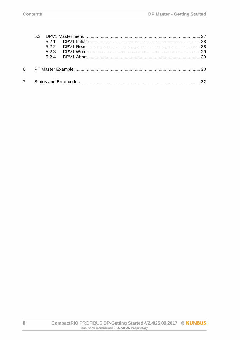
Contents DP Master - Getting Started
ii CompactRIO PROFIBUS DP-Getting Started-V2.4/25.09.2017 Business Confidential/ Proprietary
5.2 DPV1 Master menu ........................................................................................... 27 5.2.1 DPV1-Initiate ........................................................................................ 28 5.2.2 DPV1-Read .......................................................................................... 28 5.2.3 DPV1-Write .......................................................................................... 29 5.2.4 DPV1-Abort .......................................................................................... 29
6 RT Master Example .................................................................................................... 30
7 Status and Error codes ............................................................................................... 32
DP Master - Getting Started Contents
CompactRIO PROFIBUS DP-Getting Started-V2.4/25.09.2017 iii Business Confidential/ Proprietary
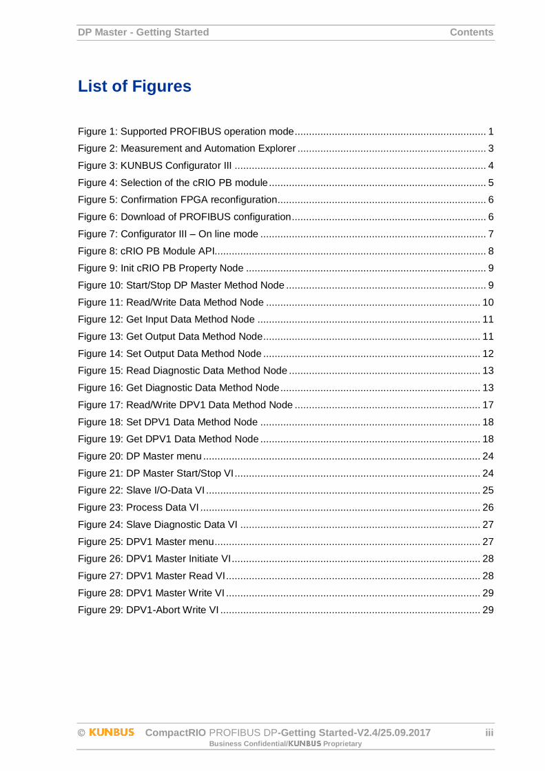
List of Figures
Figure 1: Supported PROFIBUS operation mode ................................................................... 1
Figure 2: Measurement and Automation Explorer .................................................................. 3
Figure 3: KUNBUS Configurator III ........................................................................................ 4
Figure 4: Selection of the cRIO PB module ............................................................................ 5
Figure 5: Confirmation FPGA reconfiguration......................................................................... 6
Figure 6: Download of PROFIBUS configuration .................................................................... 6
Figure 7: Configurator III – On line mode ............................................................................... 7
Figure 8: cRIO PB Module API............................................................................................... 8
Figure 9: Init cRIO PB Property Node .................................................................................... 9
Figure 10: Start/Stop DP Master Method Node ...................................................................... 9
Figure 11: Read/Write Data Method Node ........................................................................... 10
Figure 12: Get Input Data Method Node .............................................................................. 11
Figure 13: Get Output Data Method Node ............................................................................ 11
Figure 14: Set Output Data Method Node ............................................................................ 12
Figure 15: Read Diagnostic Data Method Node ................................................................... 13
Figure 16: Get Diagnostic Data Method Node ...................................................................... 13
Figure 17: Read/Write DPV1 Data Method Node ................................................................. 17
Figure 18: Set DPV1 Data Method Node ............................................................................. 18
Figure 19: Get DPV1 Data Method Node ............................................................................. 18
Figure 20: DP Master menu ................................................................................................. 24
Figure 21: DP Master Start/Stop VI ...................................................................................... 24
Figure 22: Slave I/O-Data VI ................................................................................................ 25
Figure 23: Process Data VI .................................................................................................. 26
Figure 24: Slave Diagnostic Data VI .................................................................................... 27
Figure 25: DPV1 Master menu ............................................................................................. 27
Figure 26: DPV1 Master Initiate VI ....................................................................................... 28
Figure 27: DPV1 Master Read VI ......................................................................................... 28
Figure 28: DPV1 Master Write VI ......................................................................................... 29
Figure 29: DPV1-Abort Write VI ........................................................................................... 29
Contents DP Master - Getting Started
iv CompactRIO PROFIBUS DP-Getting Started-V2.4/25.09.2017 Business Confidential/ Proprietary
List of Tables
Table 1: Initialization Options ................................................................................................. 9
Table 2: Change Mode Options ............................................................................................. 9
Table 3: Read/Write I/O-Data Parameter ............................................................................. 10
Table 4: Read/Write Process Data image ............................................................................ 10
Table 5: Get Input Data Parameter ...................................................................................... 11
Table 6: Get Output Data Parameter.................................................................................... 12
Table 7: Get Output Data Parameter.................................................................................... 12
Table 8: Read Diagnostic Data Parameter ........................................................................... 13
Table 9: Get Diagnostic Data Parameter .............................................................................. 14
Table 10: Read/Write DPV1 Data Parameter ....................................................................... 17
Table 11: DPV1 Communication Status ............................................................................... 17
Table 12: Set DPV1 Data Parameter ................................................................................... 18
Table 13: Get DPV1 Data Parameter ................................................................................... 19
Table 14: DPV1-Initiate Parameter....................................................................................... 19
Table 15: DPV1-Read Parameter ........................................................................................ 20
Table 16: DPV1-Write Parameter ......................................................................................... 20
Table 17: DPV1-Abort Request Parameter .......................................................................... 21
Table 18: DPV1-Abort Response Parameter ........................................................................ 21
Table 19: DPV1-Abort Instance Parameter .......................................................................... 22
Table 20: DPV1-Error Parameter ......................................................................................... 22
Table 21: DPV1-Error Code 1 .............................................................................................. 23
Table 22: Slave Info List Parameter ..................................................................................... 25
Table 23: Slave I/O-Data Parameter .................................................................................... 26
Table 24: Set Process Data Parameter ................................................................................ 26
Table 25: Get Process Data Parameter ............................................................................... 26
Table 26: Status and Error codes ......................................................................................... 33

DP Master - Getting Started Introduction
CompactRIO PROFIBUS DP-Getting Started-V2.4/25.09.2017 1 Business Confidential/ Proprietary
1 Introduction
This document describes the set into operation procedure of the CompactRIO PROFIBUS
DP module (cRIO PB) as DP Master.
1.1 Worldwide Support and Services The National Instruments website is your complete resource for technical support. At ni.com/support, you have access to everything from troubleshooting and application
development self-help resources to email and phone assistance from NI Application Engineers.
1.2 Prerequisites:
A cRIO PB Master/Slave module.
Download the cRIO PB Master/Slave Driver Software from the LabVIEW Tools
Network
National Instruments CompactRIO system with real time controller and chassis.
The National Instruments LabVIEW Real time and FPGA Development System from
Version 2012 installed on a Windows PC.
NI-RIO Version 14.5 or higher needs to be installed.
Please check your cRIO PB module if it supports Master/Slave operation mode. You
can find the supported operation mode on the sticker on the back side beside the SPI
plug:
Figure 1: Supported PROFIBUS operation mode
Note: The CompactRIO PROFIBUS DP modules require 2.5 W of power, so you must use it
in Slot 1 while leaving Slot 2 empty.

Introduction DP Master - Getting Started
2 CompactRIO PROFIBUS DP-Getting Started-V2.4/25.09.2017 Business Confidential/ Proprietary
Note: The CompactRIO PROFIBUS DP modules is supported only in CompactRIO
reconfigurable chassis, such as an NI cRIO-911x, and NI Single-Board RIO devices.
Note: If your cRIO PB module only supports Slave mode it cannot be operated as DP
Master.
DP Master - Getting Started Installation
CompactRIO PROFIBUS DP-Getting Started-V2.4/25.09.2017 3 Business Confidential/ Proprietary
2 Installation
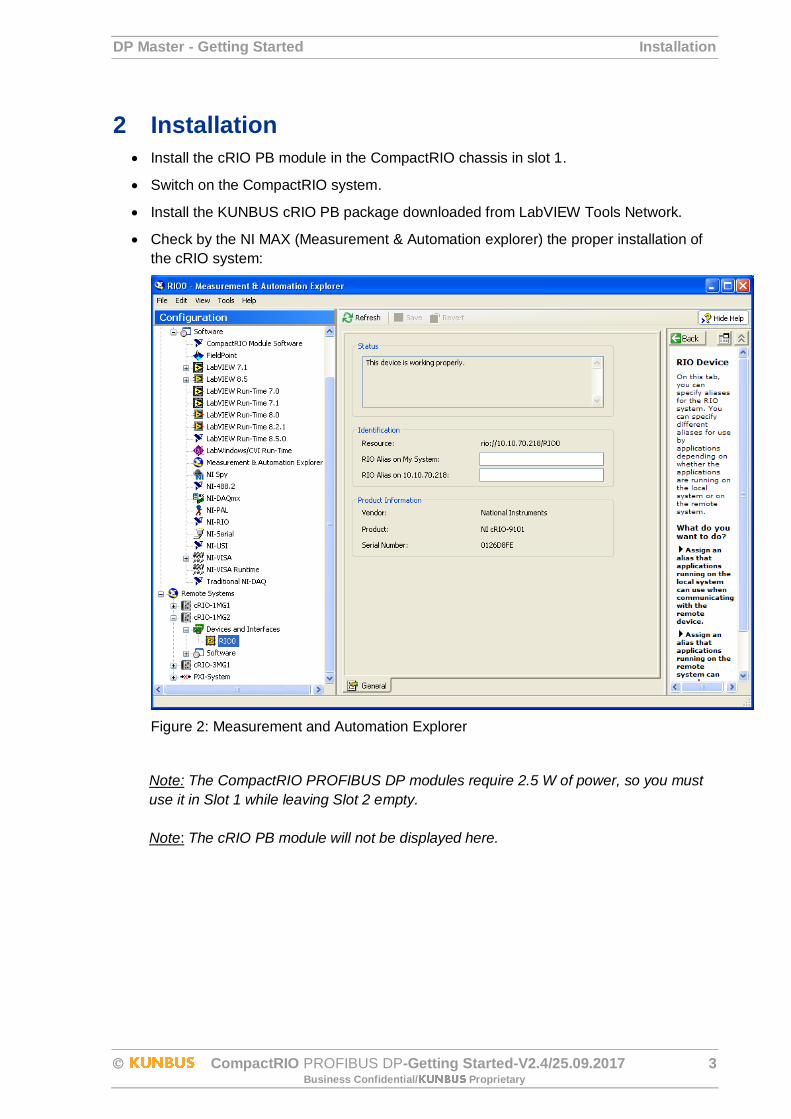
Install the cRIO PB module in the CompactRIO chassis in slot 1.
Switch on the CompactRIO system.
Install the KUNBUS cRIO PB package downloaded from LabVIEW Tools Network.
Check by the NI MAX (Measurement & Automation explorer) the proper installation of
the cRIO system:
Figure 2: Measurement and Automation Explorer
Note: The CompactRIO PROFIBUS DP modules require 2.5 W of power, so you must
use it in Slot 1 while leaving Slot 2 empty.
Note: The cRIO PB module will not be displayed here.
PROFIBUS configuration DP Master - Getting Started
4 CompactRIO PROFIBUS DP-Getting Started-V2.4/25.09.2017 Business Confidential/ Proprietary
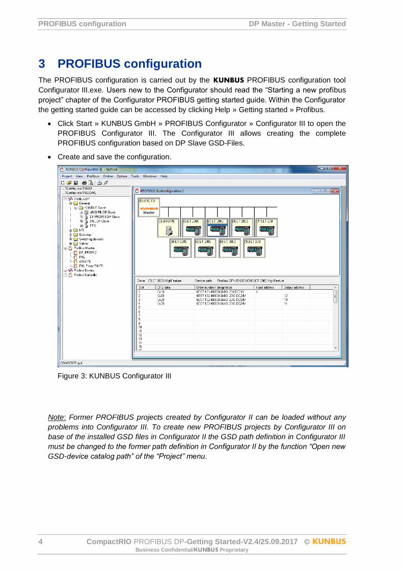
3 PROFIBUS configuration
The PROFIBUS configuration is carried out by the KUNBUS PROFIBUS configuration tool
Configurator III.exe. Users new to the Configurator should read the “Starting a new profibus
project” chapter of the Configurator PROFIBUS getting started guide. Within the Configurator
the getting started guide can be accessed by clicking Help » Getting started » Profibus.
Click Start » KUNBUS GmbH » PROFIBUS Configurator » Configurator III to open the
PROFIBUS Configurator III. The Configurator III allows creating the complete
PROFIBUS configuration based on DP Slave GSD-Files.
Create and save the configuration.
Figure 3: KUNBUS Configurator III
Note: Former PROFIBUS projects created by Configurator II can be loaded without any
problems into Configurator III. To create new PROFIBUS projects by Configurator III on
base of the installed GSD files in Configurator II the GSD path definition in Configurator III
must be changed to the former path definition in Configurator II by the function “Open new
GSD-device catalog path” of the “Project” menu.
DP Master - Getting Started PROFIBUS configuration
CompactRIO PROFIBUS DP-Getting Started-V2.4/25.09.2017 5 Business Confidential/ Proprietary
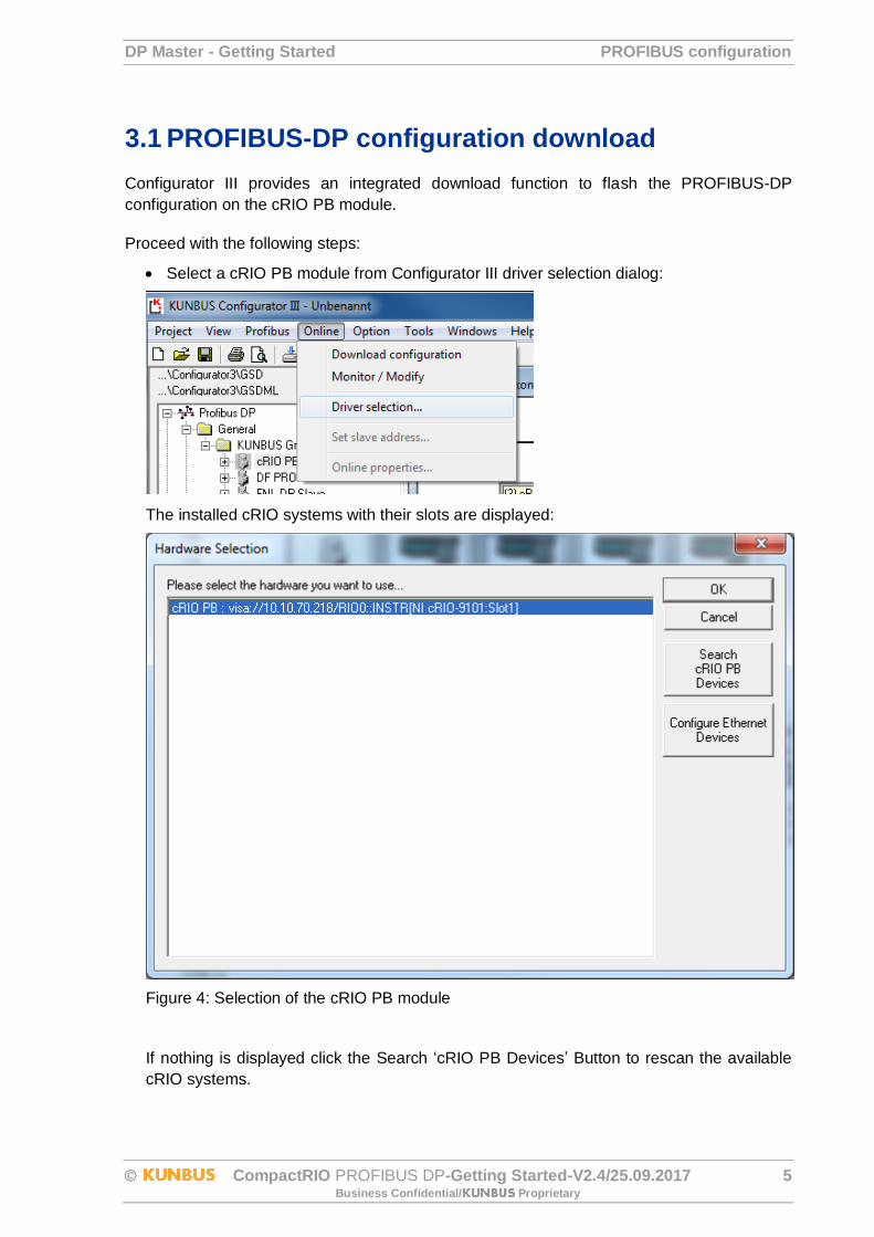
3.1 PROFIBUS-DP configuration download
Configurator III provides an integrated download function to flash the PROFIBUS-DP
configuration on the cRIO PB module.
Proceed with the following steps:
Select a cRIO PB module from Configurator III driver selection dialog:
The installed cRIO systems with their slots are displayed:
Figure 4: Selection of the cRIO PB module
If nothing is displayed click the Search ‘cRIO PB Devices’ Button to rescan the available
cRIO systems.
PROFIBUS configuration DP Master - Getting Started
6 CompactRIO PROFIBUS DP-Getting Started-V2.4/25.09.2017 Business Confidential/ Proprietary
Select the correct cRIO system.
Note: Configurator III does not detect automatically the cRIO PB module, the selection
must be correct otherwise no download is possible. Refer to the Online – Help System of
Configurator III for details of the driver selection.
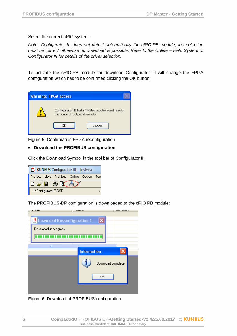
To activate the cRIO PB module for download Configurator III will change the FPGA
configuration which has to be confirmed clicking the OK button:
Figure 5: Confirmation FPGA reconfiguration
Download the PROFIBUS configuration
Click the Download Symbol in the tool bar of Configurator III:
The PROFIBUS-DP configuration is downloaded to the cRIO PB module:
Figure 6: Download of PROFIBUS configuration

DP Master - Getting Started PROFIBUS configuration
CompactRIO PROFIBUS DP-Getting Started-V2.4/25.09.2017 7 Business Confidential/ Proprietary
3.2 Configurator III Monitor/Modify mode
With the Monitor/Modify mode of the Configurator III the flashed PROFIBUS-DP
configuration can be tested immediately. Please note that the configured DP Slaves must be
connected to the cRIO PB module.
Click the Monitor/Modify symbol of the Toolbar of Configurator III:
Configurator III displays the PROFIBUS-Network in Online mode:
Figure 7: Configurator III – On line mode
Configurator III displays the status of every DP Slave (colored frame) and allows to monitor
and modify the I/O data by clicking the DP Slaves. For further details please refer to the
online help system of Configurator III.
FPGA Method and Property Nodes DP Master - Getting Started
8 CompactRIO PROFIBUS DP-Getting Started-V2.4/25.09.2017 Business Confidential/ Proprietary
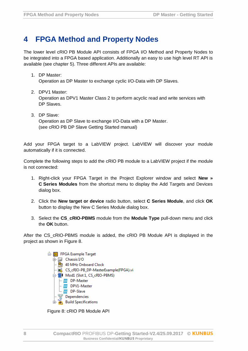
4 FPGA Method and Property Nodes
The lower level cRIO PB Module API consists of FPGA I/O Method and Property Nodes to
be integrated into a FPGA based application. Additionally an easy to use high level RT API is
available (see chapter 5). Three different APIs are available:
1. DP Master:
Operation as DP Master to exchange cyclic I/O-Data with DP Slaves.
2. DPV1 Master:
Operation as DPV1 Master Class 2 to perform acyclic read and write services with
DP Slaves.
3. DP Slave:
Operation as DP Slave to exchange I/O-Data with a DP Master.
(see cRIO PB DP Slave Getting Started manual)
Add your FPGA target to a LabVIEW project. LabVIEW will discover your module
automatically if it is connected.
Complete the following steps to add the cRIO PB module to a LabVIEW project if the module
is not connected:
1. Right-click your FPGA Target in the Project Explorer window and select New »
C Series Modules from the shortcut menu to display the Add Targets and Devices
dialog box.
2. Click the New target or device radio button, select C Series Module, and click OK
button to display the New C Series Module dialog box.
3. Select the CS_cRIO-PBMS module from the Module Type pull-down menu and click
the OK button.
After the CS_cRIO-PBMS module is added, the cRIO PB Module API is displayed in the
project as shown in Figure 8.
Figure 8: cRIO PB Module API

DP Master - Getting Started FPGA Method and Property Nodes
CompactRIO PROFIBUS DP-Getting Started-V2.4/25.09.2017 9 Business Confidential/ Proprietary
4.1 Module Property Nodes
4.1.1 Init cRIO PB Property
The Init cRIO PB Property Node configures the operation mode on the cRIO PB module. The
cRIO PB module will always start up in the last set mode.
Figure 9: Init cRIO PB Property Node
Table 1: Initialization Options
4.2 DP Master Methode Nodes
The DP Master API can handle single DP Slaves or the entire process image to handle all
DP Slaves simultaneously.
4.2.1 Start/Stop DP Master Method
Starting the DP Master activates the PROFIBUS and the DP Slave scanning.
Figure 10: Start/Stop DP Master Method Node
Table 2: Change Mode Options
Option Mode of Operation
DP/DPV1 Master Switches cRIO-PB into DP Master mode
DP-AutoSlave Switches cRIO-PB into DP-AutoSlave mode
Option Mode of Operation
Start Activates the cRIO-PB as DP Master Class 1 and Class 2
Stop Resets the cRIO-PB
FPGA Method and Property Nodes DP Master - Getting Started
10 CompactRIO PROFIBUS DP-Getting Started-V2.4/25.09.2017 Business Confidential/ Proprietary
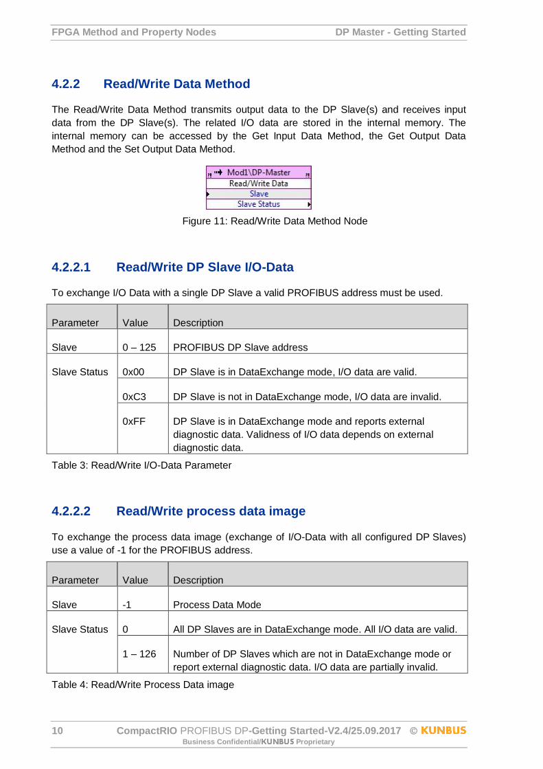
4.2.2 Read/Write Data Method
The Read/Write Data Method transmits output data to the DP Slave(s) and receives input
data from the DP Slave(s). The related I/O data are stored in the internal memory. The
internal memory can be accessed by the Get Input Data Method, the Get Output Data
Method and the Set Output Data Method.
Figure 11: Read/Write Data Method Node
4.2.2.1 Read/Write DP Slave I/O-Data
To exchange I/O Data with a single DP Slave a valid PROFIBUS address must be used.
Parameter Value Description
Slave 0 – 125 PROFIBUS DP Slave address
Slave Status 0x00 DP Slave is in DataExchange mode, I/O data are valid.
0xC3 DP Slave is not in DataExchange mode, I/O data are invalid.
0xFF DP Slave is in DataExchange mode and reports external
diagnostic data. Validness of I/O data depends on external
diagnostic data.
Table 3: Read/Write I/O-Data Parameter
4.2.2.2 Read/Write process data image
To exchange the process data image (exchange of I/O-Data with all configured DP Slaves)
use a value of -1 for the PROFIBUS address.
Parameter Value Description
Slave -1 Process Data Mode
Slave Status 0 All DP Slaves are in DataExchange mode. All I/O data are valid.
1 – 126 Number of DP Slaves which are not in DataExchange mode or
report external diagnostic data. I/O data are partially invalid.
Table 4: Read/Write Process Data image
DP Master - Getting Started FPGA Method and Property Nodes
CompactRIO PROFIBUS DP-Getting Started-V2.4/25.09.2017 11 Business Confidential/ Proprietary
If the Read/Write Process Data Image Method returns a Slave Status <> 0, perform an
additional Read Diagnostic Data Method ((see chapter 4.2.6) for every configured DP Slave
to detect failing DP Slaves.
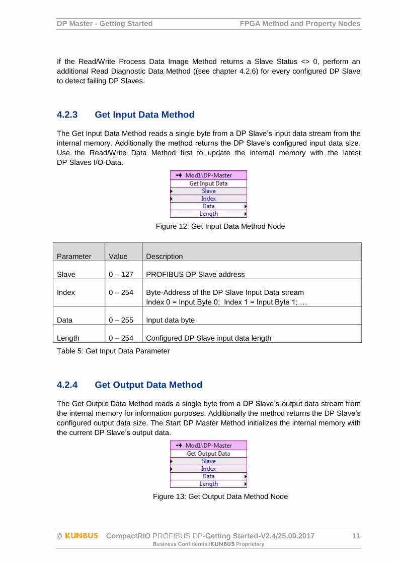
4.2.3 Get Input Data Method
The Get Input Data Method reads a single byte from a DP Slave’s input data stream from the
internal memory. Additionally the method returns the DP Slave’s configured input data size.
Use the Read/Write Data Method first to update the internal memory with the latest
DP Slaves I/O-Data.
Figure 12: Get Input Data Method Node
Parameter Value Description
Slave 0 – 127 PROFIBUS DP Slave address
Index 0 – 254 Byte-Address of the DP Slave Input Data stream
Index 0 = Input Byte 0; Index 1 = Input Byte 1; …
Data 0 – 255 Input data byte
Length 0 – 254 Configured DP Slave input data length
Table 5: Get Input Data Parameter
4.2.4 Get Output Data Method
The Get Output Data Method reads a single byte from a DP Slave’s output data stream from
the internal memory for information purposes. Additionally the method returns the DP Slave’s
configured output data size. The Start DP Master Method initializes the internal memory with
the current DP Slave’s output data.
Figure 13: Get Output Data Method Node
FPGA Method and Property Nodes DP Master - Getting Started
12 CompactRIO PROFIBUS DP-Getting Started-V2.4/25.09.2017 Business Confidential/ Proprietary
Parameter Value Description
Slave 0 – 127 PROFIBUS DP Slave address
Index 0 – 254 Byte-Address of the DP Slave Input Data stream
Index 0 = Output Byte 0; Index 1 = Output Byte 1; …
Data 0 – 255 Output data byte
Length 0 – 254 Configured DP Slave output data length
Table 6: Get Output Data Parameter
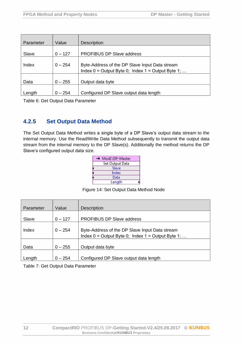
4.2.5 Set Output Data Method
The Set Output Data Method writes a single byte of a DP Slave’s output data stream to the
internal memory. Use the Read/Write Data Method subsequently to transmit the output data
stream from the internal memory to the DP Slave(s). Additionally the method returns the DP
Slave’s configured output data size.
Figure 14: Set Output Data Method Node
Parameter Value Description
Slave 0 – 127 PROFIBUS DP Slave address
Index 0 – 254 Byte-Address of the DP Slave Input Data stream
Index 0 = Output Byte 0; Index 1 = Output Byte 1; …
Data 0 – 255 Output data byte
Length 0 – 254 Configured DP Slave output data length
Table 7: Get Output Data Parameter
DP Master - Getting Started FPGA Method and Property Nodes
CompactRIO PROFIBUS DP-Getting Started-V2.4/25.09.2017 13 Business Confidential/ Proprietary
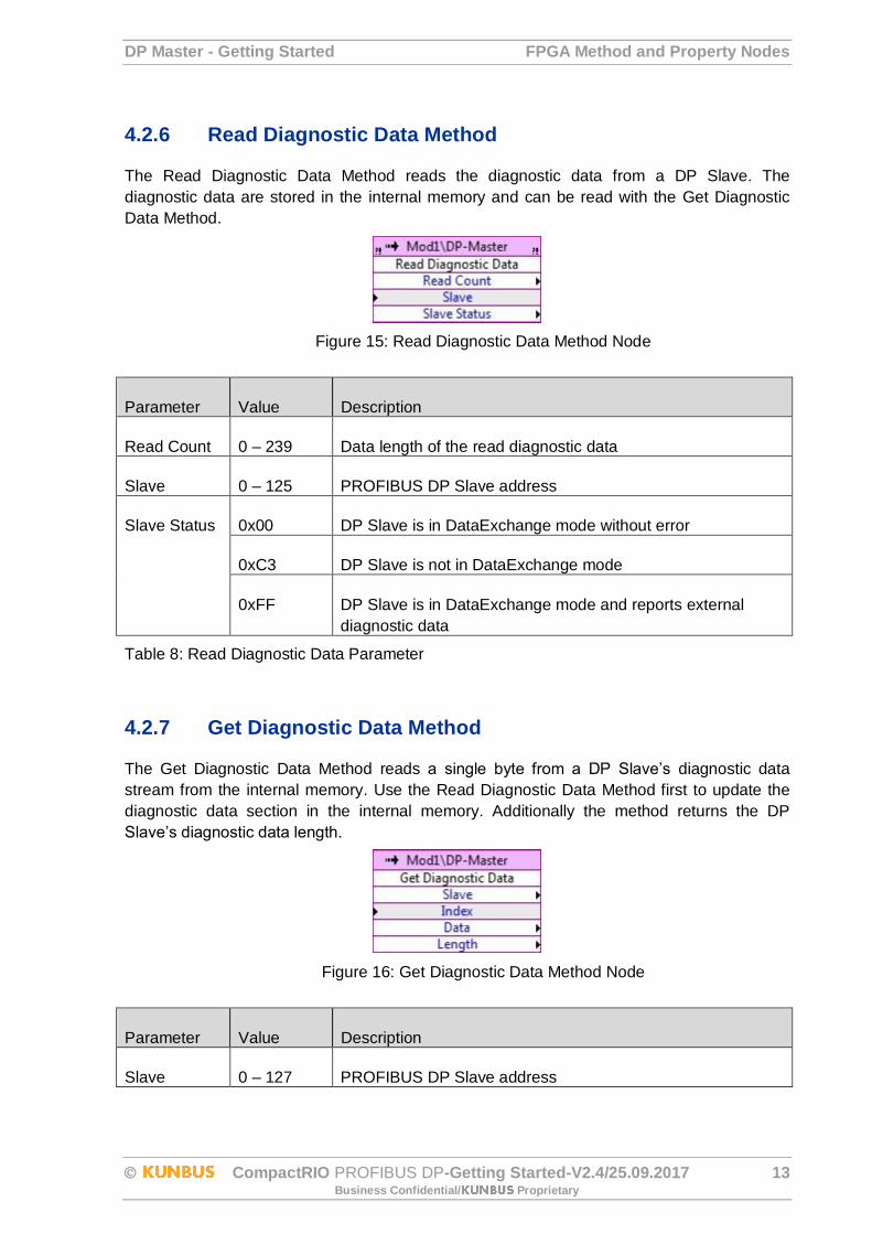
4.2.6 Read Diagnostic Data Method
The Read Diagnostic Data Method reads the diagnostic data from a DP Slave. The
diagnostic data are stored in the internal memory and can be read with the Get Diagnostic
Data Method.
Figure 15: Read Diagnostic Data Method Node
Parameter Value Description
Read Count 0 – 239 Data length of the read diagnostic data
Slave 0 – 125 PROFIBUS DP Slave address
Slave Status 0x00 DP Slave is in DataExchange mode without error
0xC3 DP Slave is not in DataExchange mode
0xFF DP Slave is in DataExchange mode and reports external
diagnostic data
Table 8: Read Diagnostic Data Parameter
4.2.7 Get Diagnostic Data Method
The Get Diagnostic Data Method reads a single byte from a DP Slave’s diagnostic data
stream from the internal memory. Use the Read Diagnostic Data Method first to update the
diagnostic data section in the internal memory. Additionally the method returns the DP
Slave’s diagnostic data length.
Figure 16: Get Diagnostic Data Method Node
Parameter Value Description
Slave 0 – 127 PROFIBUS DP Slave address
FPGA Method and Property Nodes DP Master - Getting Started
14 CompactRIO PROFIBUS DP-Getting Started-V2.4/25.09.2017 Business Confidential/ Proprietary
Index 0 – 239 Byte-Address of the DP Slave Diagnostic Data
Index 0 = Diag Byte 0; Index 1 = Diag Byte 1; …
Data 0 – 255 Diagnostic data byte
Length 0 – 238 Size of the diagnostic data
Table 9: Get Diagnostic Data Parameter
4.2.7.1 Diagnostic data description
A DP Slave’s diagnostic data stream consists of 6 bytes standard diagnostic data and up to
230 bytes device specific diagnostic data. The standard diagnostic data start at Byte 3:
Octet 1: DP Slave address
Octet 2: Diagnostic data length
Octet 3: Stationsstatus_1
Bit 7: Diag.Master_Lock
The DP Slave has been parameterized by another master. This Bit is set by the DP Master (class 1) if the address in Octet 4 unequal 255 and unequal the own address. The DP Slave sets this Bit to zero.
Bit 6: Diag.Prm_Fault
This Bit is set by the DP Slave in case the last parameter telegram has been erroneous, e.g. wrong length, wrong Ident_Number, invalid parameter.
Bit 5: Diag.Invalid_Slave_Response
This Bit is set by the DP Master as soon as an implausible answer has been received by the contacted DP Slave. The DP Slave sets this Bit to zero.
Bit 4: Diag.Not_Supported
This Bit is set by the DP Slave as soon as a function has been requested that is not supported by this DP Slave.
Bit 3: Diag.Ext_Diag
This Bit is set by the DP Slave. If the Bit is set, a diagnostic input must exist in the slave-specific diagnostic area (Ext_Diag_Data). If the Bit is not set, a status message can exist in the slave-specific diagnostic area (Ext_Diag_Data). The
meaning of this status messages is application-specific.
Bit 2: Diag.Cfg_Fault
This Bit is set by the DP Slave as soon as there is a discrepancy between the configuration data received last by the DP Master and the data determined by the DP Slave.
DP Master - Getting Started FPGA Method and Property Nodes
CompactRIO PROFIBUS DP-Getting Started-V2.4/25.09.2017 15 Business Confidential/ Proprietary
Bit 1: Diag.Station_Not_Ready
This Bit is set by the DP Slave if the DP Slave is not yet ready for the data exchange.
Bit 0: Diag.Station_Non_Existent
This Bit is set by the DP Master if the DP Slave cannot be reached via the bus. In case the Bit is set, the diagnostic Bits contain the state of the last diagnostic message or the initial value. The DP Slave sets this Bit to zero.
Octet 4: Stationsstatus_2
Bit 7: Diag.Deactivated
This Bit is set by the DP Master as soon as the DP Slave has not been marked as active in the DP Slave parameter set and been excluded from the cyclic processing. The DP Slave sets this Bit always to zero.
Bit 5: Diag.Sync_Mode
This Bit is set by the DP Slave as soon as this DP Slave has received the sync control command.
Bit 4: Diag.Freeze_Mode
This Bit is set by the DP Slave as soon as this DP Slave has received the freeze control command.
Bit 3: Diag.WD_On (Watchdog on)
This Bit is set by the DP Slave. In case this Bit is set to 1, the supervision of the DP Slave will be activated.
Bit 2: This Bit is set to 1 by the DP Slave.
Bit 1: Diag.Stat_Diag (Statistic diagnosis)
This Bit is set by the DP Slave. If it is set, the DP Master has to collect diagnostic information until this Bit will be reset. The DP Slave will for example set this Bit if it cannot provide valid user data.
Bit 0: Diag.Prm_Req
This Bit is set by the DP Slave. If it is set, the DP Slave must be reparameterized and reconfigured. The Bit will remain until a parameterization has been effected.
In case the Bit 1 and the Bit 0 is set, Bit 0 has higher priority.
Octet 5: Stationsstatus_3
Bit 7: Diag.Ext_Diag_Overflow
In case this Bit is set, more diagnostic information exists than indicated in Ext_Diag_Data. The DP Slave will for example set this Bit if more channel diagnoses exist as the DP Slave can enter into its send buffer. The DP Master will set this Bit if the DP Slave sends more diagnostic information than the DP Master can consider in its diagnostic buffer.
Bit 0 to 6: reserved
FPGA Method and Property Nodes DP Master - Getting Started
16 CompactRIO PROFIBUS DP-Getting Started-V2.4/25.09.2017 Business Confidential/ Proprietary
Octet 5: Diag.Master_Add
The address of the DP Master that has parameterized this DP Slave will be entered into this octet. In case the DP Slave has not been parameterized by a DP Master, the DP Slave will enter the address 255 into this octet.
Octet 7 to 8: Ident_Number
The supplier identification is allocated for a DP Slave type. This identification can be consulted for testing purposes as well as for the exact identification.
4.3 DPV1 Master API
The DPV1 Master API can perform acyclic read- and write services with DP Slaves
supporting DPV1 operation mode.
DPV1 is used for the configuration of complex DP Slaves like process devices, drives, etc.
storing hundreds of additional configuration values that cannot be handled only via a cyclic
PROFIBUS DP connection.
To get detailed information about the DPV1 variable directory of a specific DP Slave, please
refer to the DP Slave specific user’s guide.
To access a DPV1 variable of a DP Slave the following steps must be performed:
1. DPV1-Service Initiate:
Establish a DPV1 connection to the DP Slave.
2. DPV1-Service Read and Write:
Reads DPV1 variables from the DP Slave or Writes DPV1 variables to the DP Slave.
3. DPV1-Service Abort:
Abort the DPV1 connection if access to the DPV1 variables is no longer required.
Note: The DPV1 service DataTransport is not supported.
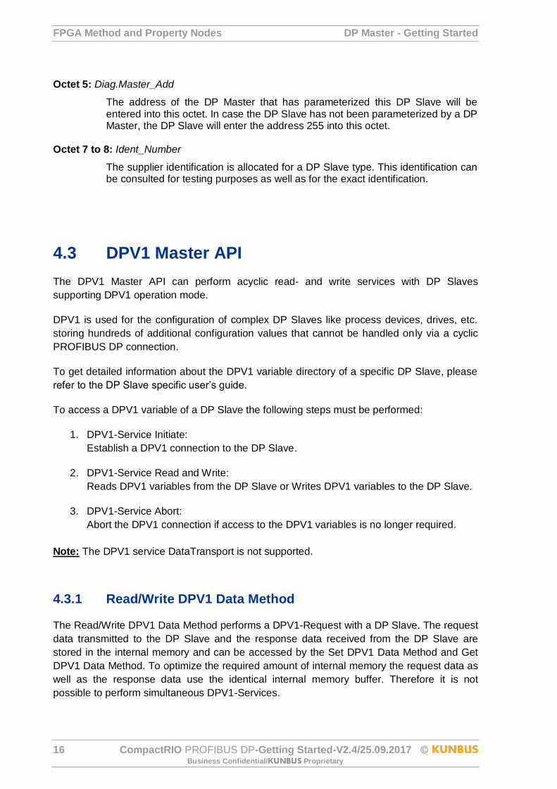
4.3.1 Read/Write DPV1 Data Method
The Read/Write DPV1 Data Method performs a DPV1-Request with a DP Slave. The request
data transmitted to the DP Slave and the response data received from the DP Slave are
stored in the internal memory and can be accessed by the Set DPV1 Data Method and Get
DPV1 Data Method. To optimize the required amount of internal memory the request data as
well as the response data use the identical internal memory buffer. Therefore it is not
possible to perform simultaneous DPV1-Services.
DP Master - Getting Started FPGA Method and Property Nodes
CompactRIO PROFIBUS DP-Getting Started-V2.4/25.09.2017 17 Business Confidential/ Proprietary
Figure 17: Read/Write DPV1 Data Method Node
Parameter Value Description
Slave 0 – 126 PROFIBUS DP Slave address
Table 10: Read/Write DPV1 Data Parameter
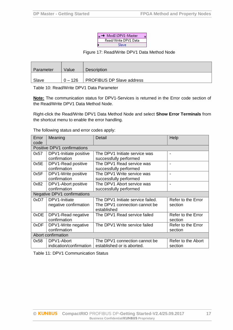
Note: The communication status for DPV1-Services is returned in the Error code section of
the Read/Write DPV1 Data Method Node.
Right-click the Read/Write DPV1 Data Method Node and select Show Error Terminals from
the shortcut menu to enable the error handling.
The following status and error codes apply:
Error code
Meaning Detail Help
Positive DPV1 confirmations
0x57 DPV1-Initiate positive confirmation
The DPV1 Initiate service was successfully performed
-
0x5E DPV1-Read positive confirmation
The DPV1 Read service was successfully performed
-
0x5F DPV1-Write positive confirmation
The DPV1 Write service was successfully performed
-
0x82 DPV1-Abort positive confirmation
The DPV1 Abort service was successfully performed
-
Negative DPV1 confirmations
0xD7 DPV1-Initiate negative confirmation
The DPV1 Initiate service failed. The DPV1 connection cannot be established
Refer to the Error section
0xDE DPV1-Read negative confirmation
The DPV1 Read service failed Refer to the Error section
0xDF DPV1-Write negative confirmation
The DPV1 Write service failed Refer to the Error section
Abort confirmation
0x58 DPV1-Abort indication/confirmation
The DPV1 connection cannot be established or is aborted.
Refer to the Abort section
Table 11: DPV1 Communication Status
FPGA Method and Property Nodes DP Master - Getting Started
18 CompactRIO PROFIBUS DP-Getting Started-V2.4/25.09.2017 Business Confidential/ Proprietary
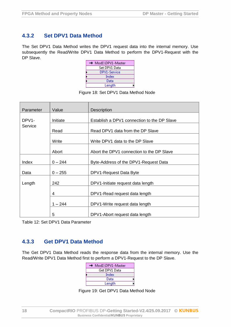
4.3.2 Set DPV1 Data Method
The Set DPV1 Data Method writes the DPV1 request data into the internal memory. Use
subsequently the Read/Write DPV1 Data Method to perform the DPV1-Request with the
DP Slave.
Figure 18: Set DPV1 Data Method Node
Parameter Value Description
DPV1-
Service
Initiate Establish a DPV1 connection to the DP Slave
Read Read DPV1 data from the DP Slave
Write Write DPV1 data to the DP Slave
Abort Abort the DPV1 connection to the DP Slave
Index 0 – 244 Byte-Address of the DPV1-Request Data
Data 0 – 255 DPV1-Request Data Byte
Length 242 DPV1-Initiate request data length
4 DPV1-Read request data length
1 – 244 DPV1-Write request data length
5 DPV1-Abort request data length
Table 12: Set DPV1 Data Parameter
4.3.3 Get DPV1 Data Method
The Get DPV1 Data Method reads the response data from the internal memory. Use the
Read/Write DPV1 Data Method first to perform a DPV1-Request to the DP Slave.
Figure 19: Get DPV1 Data Method Node

DP Master - Getting Started FPGA Method and Property Nodes
CompactRIO PROFIBUS DP-Getting Started-V2.4/25.09.2017 19 Business Confidential/ Proprietary
Parameter Value Description
Index 0 – 254 Byte-Address of the DPV1-Response Data
Data 0 – 255 DPV1-Response Data Byte
Length 241 DPV1-Initiate positive confirmation data length
1 – 243 DPV1-Read positive confirmation data length
2 DPV1-Write positive confirmation data length
8 DPV1-Abort indication data length
5 DPV1-Initiate/Read/Write negative confirmation length
Table 13: Get DPV1 Data Parameter
4.3.4 DPV1-Request/Response Data
4.3.4.1 DPV1-Initiate
Request Data Response Data
Index Description Index Description
0 Communication ref. 0 Communication ref.
1 PROFIBUS Address 1 PROFIBUS Address
2 Send timeout LB 2 Feat. Supp. 1
3 Send timeout HB 3 Feat. Supp. 2
4 Feat. Supp. 1 4 Profile Feat. Supp. 1
5 Feat. Supp. 2 5 Profile Feat. Supp. 2
6 Profile Feat. Supp. 1 6 Profile ID number LB
7 Profile Feat. Supp. 2 7 Profile ID number HB
8 Profile ID number LB 8 S-Type
9 Profile ID number HB 9 S-Length
10 S-Type 10 D-Type
11 S-Length 11 D-Length
12 D-Type 12 Data[0]
13 D-Length 13 Data[1]
14 Data[0] 14 Data[2]
15 Data[1] 15 Data[3]
… …
242 Data[228] 240 Max length data unit
Table 14: DPV1-Initiate Parameter
FPGA Method and Property Nodes DP Master - Getting Started
20 CompactRIO PROFIBUS DP-Getting Started-V2.4/25.09.2017 Business Confidential/ Proprietary
The communication status of a successful DPV1-Initiate is 0x57 and is returned in the Error
code of the Read/Write DPV1 Data Method Node. For a DPV1-Abort indication (Error code
0x58) refer to 4.3.4.5 DPV1-Abort Indication and for a negative confirmation (Error code
0xD7) refer to 4.3.4.6 DPV1-Error (Negative Confirmation).
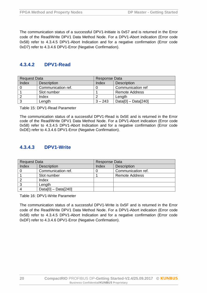
4.3.4.2 DPV1-Read
Request Data Response Data
Index Description Index Description
0 Communication ref. 0 Communication ref
1 Slot number 1 Remote Address
2 Index 2 Length
3 Length 3 – 243 Data[0] – Data[240]
Table 15: DPV1-Read Parameter
The communication status of a successful DPV1-Read is 0x5E and is returned in the Error code of the Read/Write DPV1 Data Method Node. For a DPV1-Abort indication (Error code 0x58) refer to 4.3.4.5 DPV1-Abort Indication and for a negative confirmation (Error code 0xDE) refer to 4.3.4.6 DPV1-Error (Negative Confirmation).
4.3.4.3 DPV1-Write
Request Data Response Data
Index Description Index Description
0 Communication ref. 0 Communication ref.
1 Slot number 1 Remote Address
2 Index
3 Length
4 Data[0] – Data[240]
Table 16: DPV1-Write Parameter
The communication status of a successful DPV1-Write is 0x5F and is returned in the Error
code of the Read/Write DPV1 Data Method Node. For a DPV1-Abort indication (Error code
0x58) refer to 4.3.4.5 DPV1-Abort Indication and for a negative confirmation (Error code
0xDF) refer to 4.3.4.6 DPV1-Error (Negative Confirmation).
DP Master - Getting Started FPGA Method and Property Nodes
CompactRIO PROFIBUS DP-Getting Started-V2.4/25.09.2017 21 Business Confidential/ Proprietary
4.3.4.4 DPV1-Abort
Request Data
Index Description
0 Communication ref. returned by the DPV1-Initiate service
1 Subnet
2 Instance & Reasoncode
3 Reason code
4 Additional Detail LB
5 Additional Detail HB
Table 17: DPV1-Abort Request Parameter
The communication status of a successful DPV1-Abort is 0x82 and is returned in the Error
code of the Read/Write DPV1 Data Method Node. For a DPV1-Abort indication (Error code
0x58) refer to 4.3.4.5 DPV1-Abort Indication.
4.3.4.5 DPV1-Abort Indication
If the Error code of the Read/Write DPV1 Data Method Node returns a DPV1-Abort Indication
read the response data by the Get DPV1 Data Method Node for detailed error information.
Response Data
Index Description
0 Remote Address
1 Response SAP
2 Instance
3 Reason code
4 Additional Detail LB
5 Additional Detail HB
Table 18: DPV1-Abort Response Parameter
The instance code FDL (=0) means that the physical connection to the DP Slave is not o.k
and the physical connection and the parameter Slave address have to be checked.
The instance code MSAC2_C2 (=1) means that the connection setup on DPV1 level failed
and the parameters of the DPV1-Initiate have to be checked.
Instance Reason code
Name Meaning
0 (FDL) 1 UE see EN 50170 Part 2
2 RR see EN 50170 Part 2
3 RS see EN 50170 Part 2
9 NR see EN 50170 Part 2
10 DH see EN 50170 Part 2
11 LR see EN 50170 Part 2
12 RDL see EN 50170 Part 2
13 RDH see EN 50170 Part 2
14 DS master is not in the logical ring

FPGA Method and Property Nodes DP Master - Getting Started
22 CompactRIO PROFIBUS DP-Getting Started-V2.4/25.09.2017 Business Confidential/ Proprietary
15 NA No response from remote FDL
1 (MSAC_C2) 1 ABT_SE sequence error; service not allowed in this state
2 ABT_FE invalid request PDU received
3 ABT_TO timeout of the connection
4 ABT_RE invalid response PDU received
5 ABT_IV invalid service from USER
6 ABT_STO Send_Timeout requested was to small
7 ABT_IA invalid additional address information
8 ABT_OC Waiting for FDL_DATA_REPLY.con
Table 19: DPV1-Abort Instance Parameter
Additional_Detail:
This parameter contains the minimum Send_Timeout required by the DP Slave if the
instance is MSAC_C2 and the Reason_Code is ABT_STO. The parameter Send timeout in
the DPV1 Initiate tab has to be set at minimum to this value.
4.3.4.6 DPV1-Error (Negative Confirmation)
If the Error code of the Read/Write DPV1 Data Method Node returns a negative confirmation
read the response data with the Get DPV1 Data Method Node for detailed information of the
failure.
Response Data
Index Description
0 Communication ref.
1 Remote Address
2 Error decode
3 Error code 1
4 Error code 2
Table 20: DPV1-Error Parameter
DP Master - Getting Started FPGA Method and Property Nodes
CompactRIO PROFIBUS DP-Getting Started-V2.4/25.09.2017 23 Business Confidential/ Proprietary
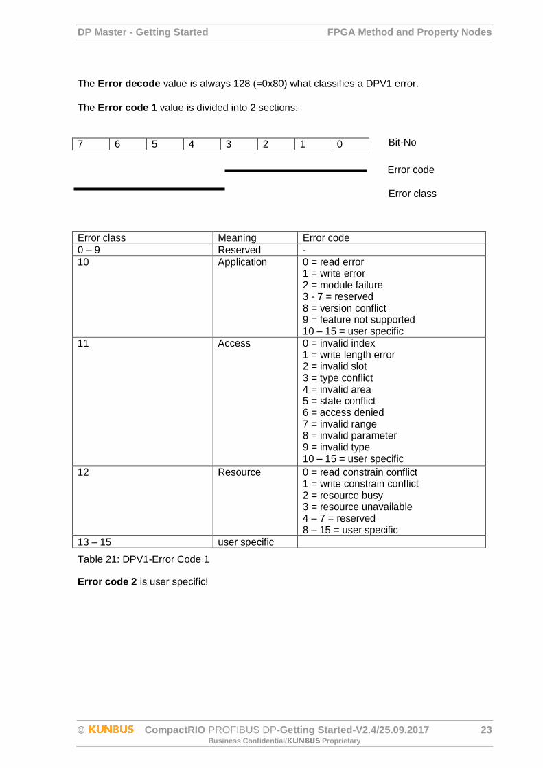
The Error decode value is always 128 (=0x80) what classifies a DPV1 error.
The Error code 1 value is divided into 2 sections:
7 6 5 4 3 2 1 0
Error class Meaning Error code
0 – 9 Reserved -
10 Application 0 = read error 1 = write error 2 = module failure 3 - 7 = reserved 8 = version conflict 9 = feature not supported 10 – 15 = user specific
11 Access 0 = invalid index 1 = write length error 2 = invalid slot 3 = type conflict 4 = invalid area 5 = state conflict 6 = access denied 7 = invalid range 8 = invalid parameter 9 = invalid type 10 – 15 = user specific
12 Resource 0 = read constrain conflict 1 = write constrain conflict 2 = resource busy 3 = resource unavailable 4 – 7 = reserved 8 – 15 = user specific
13 – 15 user specific
Table 21: DPV1-Error Code 1
Error code 2 is user specific!
Error code
Error class
Bit-No

LabVIEW RT PROFIBUS DP Master VIs DP Master - Getting Started
24 CompactRIO PROFIBUS DP-Getting Started-V2.4/25.09.2017 Business Confidential/ Proprietary
5 LabVIEW RT PROFIBUS DP Master VIs
The RT DP Master VIs provide access to the PROFIBUS on RT-Level via the already
described low level FPGA VIs. Refer to the RT Master Example for a fully working
implementation example. The VI specific context help menu describes in detail all VI specific
parameters.
5.1 DP Master menu
Use the cRIO PB palettes to access the RT DP Master VIs. Click Functions Palette » Addons
» KUNBUS Librarys » cRIO PB Master/Slave » DP Master:
Figure 20: DP Master menu
5.1.1 DP Master Start/Stop
The CS_cRIO-PB_DP Master_StartStop.vi starts and stops the cRIO PB as PROFIBUS
Master.
Figure 21: DP Master Start/Stop VI
Refer to Table 2 for a list of DP Master Change Mode Options.
DP Master - Getting Started LabVIEW RT PROFIBUS DP Master VIs
CompactRIO PROFIBUS DP-Getting Started-V2.4/25.09.2017 25 Business Confidential/ Proprietary
The CS_cRIO-PB_DP Master_StartStop.vi returns a list of additional parameters describing
input and output lengths of the configured DP Slaves:
Parameter Value Description
Address 0 – 127 Configured DP Slave Address
Input Lenth 0 – 255 Configured DP Slave input data length
Output Length 0 – 255 Configured DP Slave output data length
Table 22: Slave Info List Parameter
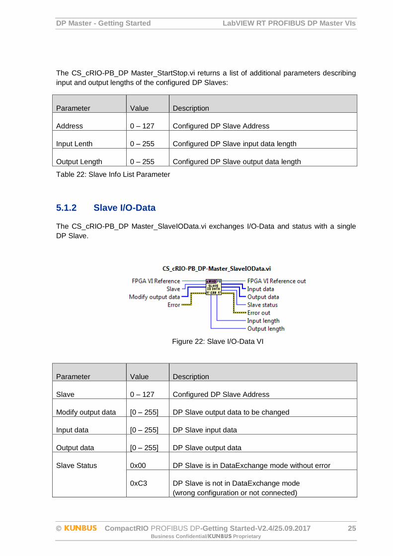
5.1.2 Slave I/O-Data
The CS_cRIO-PB_DP Master_SlaveIOData.vi exchanges I/O-Data and status with a single
DP Slave.
Figure 22: Slave I/O-Data VI
Parameter Value Description
Slave 0 – 127 Configured DP Slave Address
Modify output data [0 – 255] DP Slave output data to be changed
Input data [0 – 255] DP Slave input data
Output data [0 – 255] DP Slave output data
Slave Status 0x00 DP Slave is in DataExchange mode without error
0xC3 DP Slave is not in DataExchange mode
(wrong configuration or not connected)
LabVIEW RT PROFIBUS DP Master VIs DP Master - Getting Started
26 CompactRIO PROFIBUS DP-Getting Started-V2.4/25.09.2017 Business Confidential/ Proprietary
0xFF DP Slave is in DataExchange mode and reports
external diagnostic data
Input Lenth 0 – 255 Configured DP Slave input data length
Output Length 0 – 255 Configured DP Slave output data length
Table 23: Slave I/O-Data Parameter
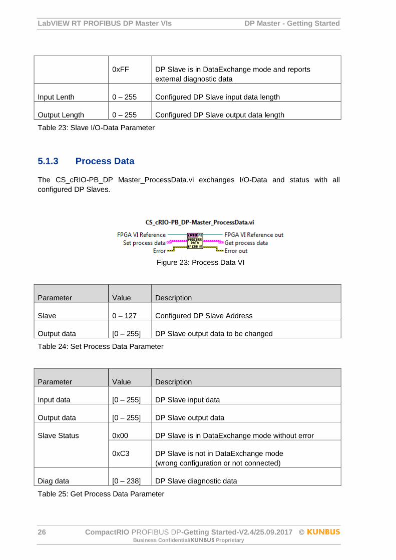
5.1.3 Process Data
The CS_cRIO-PB_DP Master_ProcessData.vi exchanges I/O-Data and status with all
configured DP Slaves.
Figure 23: Process Data VI
Parameter Value Description
Slave 0 – 127 Configured DP Slave Address
Output data [0 – 255] DP Slave output data to be changed
Table 24: Set Process Data Parameter
Parameter Value Description
Input data [0 – 255] DP Slave input data
Output data [0 – 255] DP Slave output data
Slave Status 0x00 DP Slave is in DataExchange mode without error
0xC3 DP Slave is not in DataExchange mode
(wrong configuration or not connected)
Diag data [0 – 238] DP Slave diagnostic data
Table 25: Get Process Data Parameter
DP Master - Getting Started LabVIEW RT PROFIBUS DP Master VIs
CompactRIO PROFIBUS DP-Getting Started-V2.4/25.09.2017 27 Business Confidential/ Proprietary
5.1.4 Cyclic Slave Diag Data
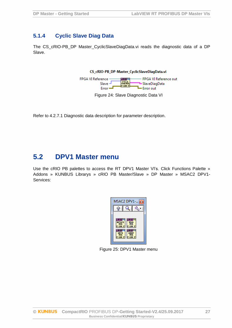
The CS_cRIO-PB_DP Master_CyclicSlaveDiagData.vi reads the diagnostic data of a DP
Slave.
Figure 24: Slave Diagnostic Data VI
Refer to 4.2.7.1 Diagnostic data description for parameter description.
5.2 DPV1 Master menu
Use the cRIO PB palettes to access the RT DPV1 Master VI’s. Click Functions Palette »
Addons » KUNBUS Librarys » cRIO PB Master/Slave » DP Master » MSAC2 DPV1-
Services:
Figure 25: DPV1 Master menu

LabVIEW RT PROFIBUS DP Master VIs DP Master - Getting Started
28 CompactRIO PROFIBUS DP-Getting Started-V2.4/25.09.2017 Business Confidential/ Proprietary
5.2.1 DPV1-Initiate
The CS_cRIO-PB_MSAC2_DPV1-InitiateReq.vi establishes a connection to a DPV1 Slave.
Figure 26: DPV1 Master Initiate VI
Refer to Table 14 for a list of DPV1-Initiate Parameter.
5.2.2 DPV1-Read
The CS_cRIO-PB_MSAC2_DPV1-ReadReq performs a DPV1-Read service with a DPV1
Slave.
Figure 27: DPV1 Master Read VI
Refer to DPV1-Read ParameterTable 15 for a list of DPV1-Read Parameter.
DP Master - Getting Started LabVIEW RT PROFIBUS DP Master VIs
CompactRIO PROFIBUS DP-Getting Started-V2.4/25.09.2017 29 Business Confidential/ Proprietary
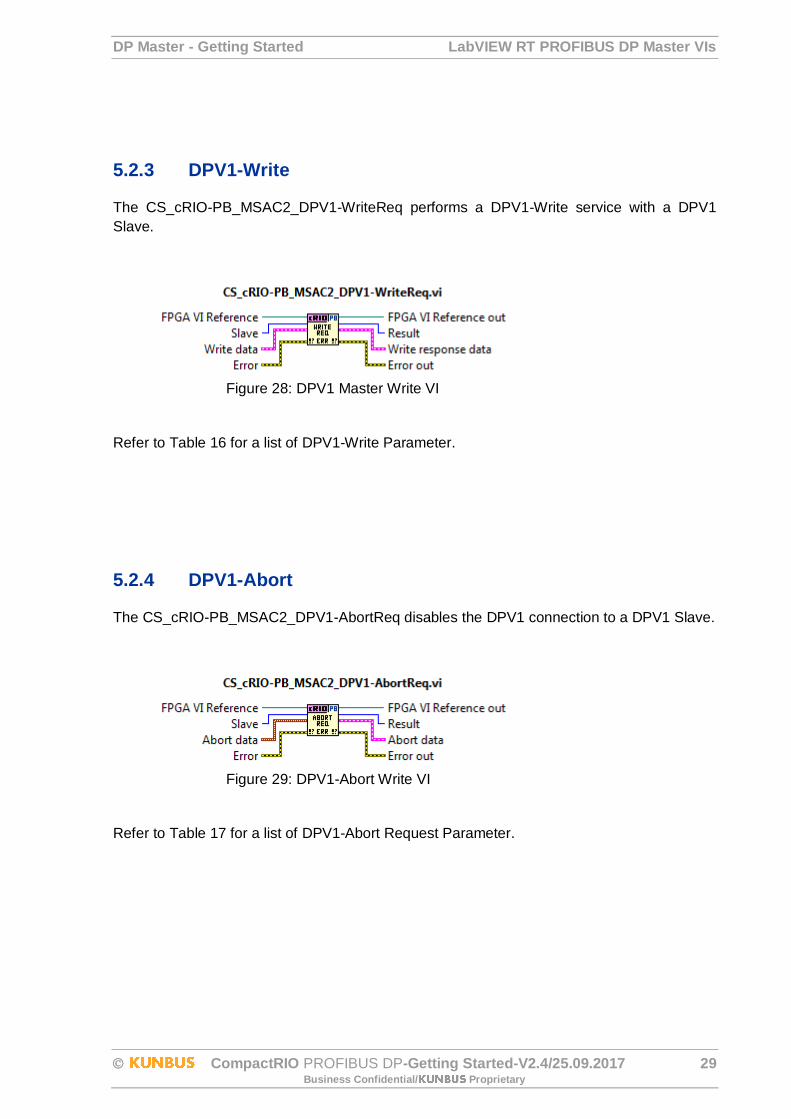
5.2.3 DPV1-Write
The CS_cRIO-PB_MSAC2_DPV1-WriteReq performs a DPV1-Write service with a DPV1
Slave.
Figure 28: DPV1 Master Write VI
Refer to Table 16 for a list of DPV1-Write Parameter.
5.2.4 DPV1-Abort
The CS_cRIO-PB_MSAC2_DPV1-AbortReq disables the DPV1 connection to a DPV1 Slave.
Figure 29: DPV1-Abort Write VI
Refer to Table 17 for a list of DPV1-Abort Request Parameter.
RT Master Example DP Master - Getting Started
30 CompactRIO PROFIBUS DP-Getting Started-V2.4/25.09.2017 Business Confidential/ Proprietary
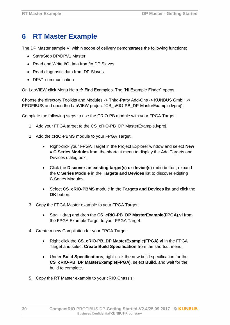
6 RT Master Example
The DP Master sample VI within scope of delivery demonstrates the following functions:
Start/Stop DP/DPV1 Master
Read and Write I/O data from/to DP Slaves
Read diagnostic data from DP Slaves
DPV1 communication
On LabVIEW click Menu Help Find Examples. The “NI Example Finder” opens.
Choose the directory Toolkits and Modules -> Third-Party Add-Ons -> KUNBUS GmbH ->
PROFIBUS and open the LabVIEW project “CS_cRIO-PB_DP-MasterExample.lvproj”.
Complete the following steps to use the CRIO PB module with your FPGA Target:
1. Add your FPGA target to the CS_cRIO-PB_DP MasterExample.lvproj.
2. Add the cRIO-PBMS module to your FPGA Target:
Right-click your FPGA Target in the Project Explorer window and select New
» C Series Modules from the shortcut menu to display the Add Targets and
Devices dialog box.
Click the Discover an existing target(s) or device(s) radio button, expand
the C Series Module in the Targets and Devices list to discover existing
C Series Modules.
Select CS_cRIO-PBMS module in the Targets and Devices list and click the
OK button.
3. Copy the FPGA Master example to your FPGA Target:
Strg + drag and drop the CS_cRIO-PB_DP MasterExample(FPGA).vi from
the FPGA Example Target to your FPGA Target.
4. Create a new Compilation for your FPGA Target:
Right-click the CS_cRIO-PB_DP MasterExample(FPGA).vi in the FPGA
Target and select Create Build Specification from the shortcut menu.
Under Build Specifications, right-click the new build specification for the
CS_cRIO-PB_DP MasterExample(FPGA), select Build, and wait for the
build to complete.
5. Copy the RT Master example to your cRIO Chassis:
DP Master - Getting Started RT Master Example
CompactRIO PROFIBUS DP-Getting Started-V2.4/25.09.2017 31 Business Confidential/ Proprietary
Strg + drag and drop the CS_cRIO-PB_DP MasterExample(Host).vi from the
FPGA Example Target to your FPGA Target.
6. Configure Open FPGA VI Reference to communicate between the Host VI and
FPGA VI.
Double-click the RT Master example CS_cRIO-PB_DP
MasterExample(Host).vi and select Window»Show Block Diagram.
Right-click the Open FPGA VI Reference function and select Configure Open
FPGA VI Reference from the shortcut menu to display the Configure Open
FPGA VI Reference dialog box.
Click the VI radio button, select CS_cRIO-PB_DP MasterExample(FPGA).vi
in the Select VI dialog box and click the OK button.
Run the CS_cRIO-PB_DP MasterExample(Host).vi and following the Instructions in the DP
Master section.
Status and Error codes DP Master - Getting Started
32 CompactRIO PROFIBUS DP-Getting Started-V2.4/25.09.2017 Business Confidential/ Proprietary
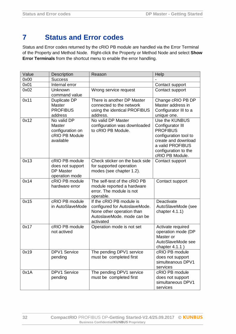
7 Status and Error codes
Status and Error codes returned by the cRIO PB module are handled via the Error Terminal
of the Property and Method Node. Right-click the Property or Method Node and select Show
Error Terminals from the shortcut menu to enable the error handling.
Value Description Reason Help
0x00 Success -
0x01 Internal error Contact support
0x02 Unknown command value
Wrong service request Contact support
0x11 Duplicate DP Master PROFIBUS address
There is another DP Master connected to the network using the identical PROFIBUS address.
Change cRIO PB DP Master address in Configurator III to a unique one.
0x12 No valid DP Master configuration on cRIO PB Module available
No valid DP Master configuration was downloaded to cRIO PB Module.
Use the KUNBUS Configurator III PROFIBUS configuration tool to create and download a valid PROFIBUS configuration to the cRIO PB Module.
0x13 cRIO PB module does not support DP Master operation mode
Check sticker on the back side for supported operation modes (see chapter 1.2).
Contact support
0x14 cRIO PB module hardware error
The self-test of the cRIO PB module reported a hardware error. The module is not operable.
Contact support
0x15 cRIO PB module in AutoSlaveMode
If the cRIO PB module is configured for AutoslaveMode. None other operation than AutoslaveMode. mode can be activated
Deactivate AutoSlaveMode (see chapter 4.1.1)
0x17 cRIO PB module not actived
Operation mode is not set Activate required operation mode (DP Master or AutoSlaveMode see chapter 4.1.1 )
0x19 DPV1 Service pending
The pending DPV1 service must be completed first
cRIO PB module does not support simulteanous DPV1 services
0x1A DPV1 Service pending
The pending DPV1 service must be completed first
cRIO PB module does not support simultaneous DPV1 services
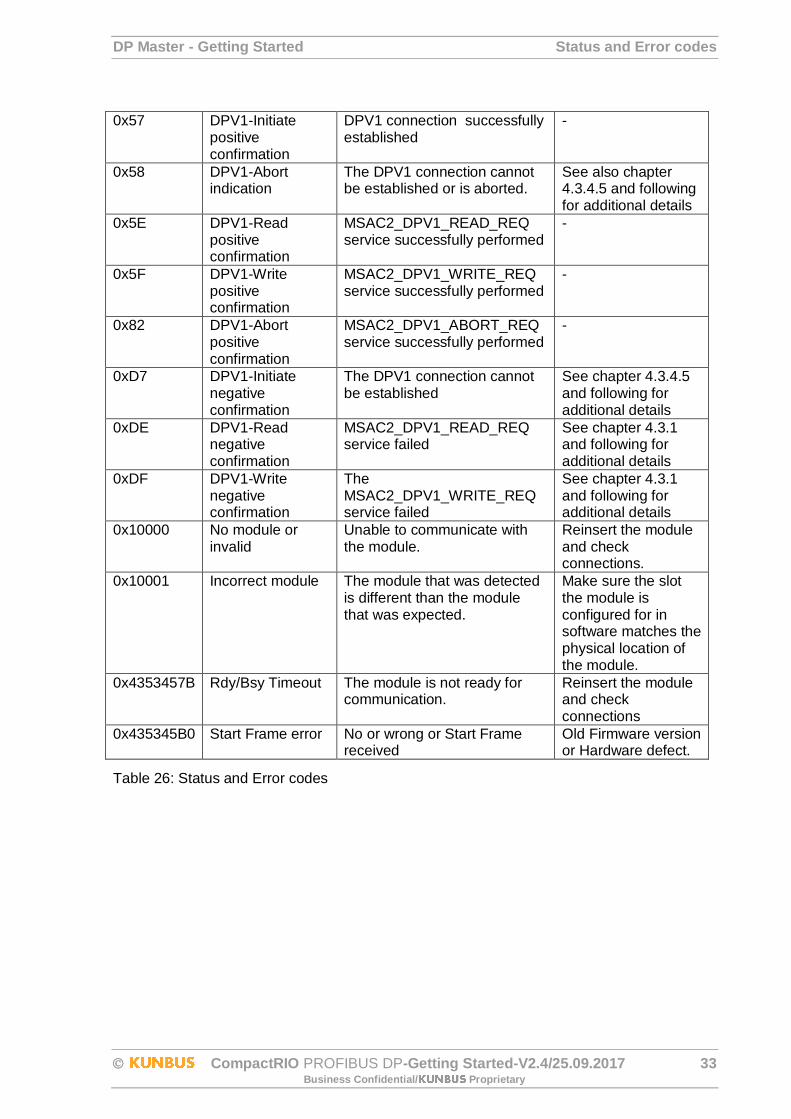
DP Master - Getting Started Status and Error codes
CompactRIO PROFIBUS DP-Getting Started-V2.4/25.09.2017 33 Business Confidential/ Proprietary
0x57 DPV1-Initiate positive confirmation
DPV1 connection successfully established
-
0x58 DPV1-Abort indication
The DPV1 connection cannot be established or is aborted.
See also chapter 4.3.4.5 and following for additional details
0x5E DPV1-Read positive confirmation
MSAC2_DPV1_READ_REQ service successfully performed
-
0x5F DPV1-Write positive confirmation
MSAC2_DPV1_WRITE_REQ service successfully performed
-
0x82 DPV1-Abort positive confirmation
MSAC2_DPV1_ABORT_REQ service successfully performed
-
0xD7 DPV1-Initiate negative confirmation
The DPV1 connection cannot be established
See chapter 4.3.4.5 and following for additional details
0xDE DPV1-Read negative confirmation
MSAC2_DPV1_READ_REQ service failed
See chapter 4.3.1 and following for additional details
0xDF DPV1-Write negative confirmation
The MSAC2_DPV1_WRITE_REQ service failed
See chapter 4.3.1 and following for additional details
0x10000 No module or invalid
Unable to communicate with the module.
Reinsert the module and check connections.
0x10001 Incorrect module The module that was detected is different than the module that was expected.
Make sure the slot the module is configured for in software matches the physical location of the module.
0x4353457B Rdy/Bsy Timeout The module is not ready for communication.
Reinsert the module and check connections
0x435345B0 Start Frame error No or wrong or Start Frame received
Old Firmware version or Hardware defect.
Table 26: Status and Error codes

© 2018 National Instruments. All rights reserved.
377816A-01 Sep18
Information is subject to change without notice. Refer to the NI Trademarks and Logo Guidelines at ni.com/trademarks for more information on NI trademarks. Other product and company names mentioned herein are trademarks or trade names of their respective companies. For patents covering NI products/technology, refer to the appropriate location: Help»Patents in your software, the patents.txt file on your media, or the National Instruments Patents Notice at ni.com/patents. You can find information about end-user license agreements (EULAs) and third-party legal notices in the readme file for your NI product. Refer to the Export Compliance Information at ni.com/legal/export-compliance for the NI global trade compliance policy and how to obtain relevant HTS codes, ECCNs, and other import/export data. NI MAKES NO EXPRESS OR IMPLIED WARRANTIES AS TO THE ACCURACY OF THE INFORMATION CONTAINED HEREIN AND SHALL NOT BE LIABLE FOR ANY ERRORS. U.S. Government Customers: The data contained in this manual was developed at private expense and is subject to the applicable limited rights and restricted data rights as set forth in FAR 52.227-14, DFAR 252.227-7014, and DFAR 252.227-7015.

![PROFIBUS DP bus interface, PROFIBUS DP [BU 2700]...Sicherheit/PROFIBUS DP [BU 2700]/Bestimmungsgemäße Ver wendung PROFIBUS DP @ 8\mod_1461835577600_388.docx @ 2249429 @ 2 @ 1 2.1](https://img.pdfslide.us/doc/110x75/60b54c574bd00c04b50e633d/profibus-dp-bus-interface-profibus-dp-bu-2700-sicherheitprofibus-dp-bu.jpg)