Embed Size (px)
Citation preview
EN 2061/19
Prof. Doolla
Introduction
Analysis
EN 206 - Power Electronics and MachinesTransformers
Suryanarayana DoollaDepartment of Energy Science and Engineering
Indian Institute of Technology, [email protected]

EN 2062/19
Prof. Doolla
Introduction
Analysis
Lecture Organization - Modules
Introduction and Power Semiconductor Switches
Module 1: Transformers
Module 2: AC/DC converter / Rectifier
Module 3: DC machines and Drives
Module 4: DC/DC converter
Module 5: Induction Machine
Module 6: DC/AC converter / Inverter
Module 7: AC/AC converter / Cyclo converter
Module 8: Synchronous Machine
Module 9: Special Topics: Machines, HVDC, APF

EN 2063/19
Prof. Doolla
Introduction
Analysis
Definition
Transformer is a device or a machine, that transferselectrical energy from one electrical circuit to anotherelectrical circuit through the medium of magnetic field andwithout change in frequency.
It is possible to step up or step down the voltage/currentof a transformer, but the frequency remains constant.

EN 2064/19
Prof. Doolla
Introduction
Analysis
Types of Transformers
Voltage Level
Step Up
Step Down
Isolation
Construction
Core
Shell
Application
Power Transformer
Distribution Transformer
Generation Transformer
Connection
Star-Star, Star-Delta
Delta-Delta, Delta-Star
The principle of operation remains the same, irrespective ofvoltage level, type, size and usage pattern.

EN 2065/19
Prof. Doolla
Introduction
Analysis
Distribution Transformers
Pole Mounted Features
Ratings:CRGO SiliconSteel Transformers - Upto167 kVA, AmorphousMetal Transformers - Upto167 kVA
Cooling : ONAN, OA
Primary voltage (Upto 33 kV), Secondary Voltage (120,120/240, 210-105, 250, 240/480 V)
Winding material : Copper / Aluminium
Tapping range : 5% in steps of 2.5%1
1Ref: http://www.vijaielectricals.com

EN 2066/19
Prof. Doolla
Introduction
Analysis
Power Transformers
Power Transformer Features
Small (10-25MVA,12-66kV)
Medium (Up to 30 MVA,Up to 132 kV)
Large (25 to 500 MVA, 11to 765 kV)
Cooling: ONAN, ONAF
Winding material : Copper
2
2Ref: http://www.cgglobal.com
EN 2067/19
Prof. Doolla
Introduction
Analysis
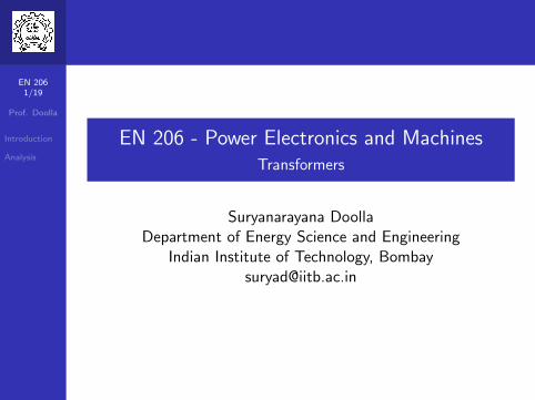
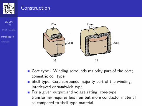
Construction
Core type : Winding sorrounds majority part of the core;conentric coil typeShell type: Core surrounds majority part of the winding,interleaved or sandwich typeFor a given output and volage rating, core-typetransformer requires less iron but more conductor materialas compared to shell-type material
EN 2068/19
Prof. Doolla
Introduction
Analysis
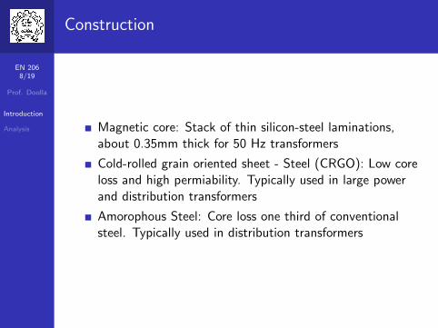
Construction
Magnetic core: Stack of thin silicon-steel laminations,about 0.35mm thick for 50 Hz transformers
Cold-rolled grain oriented sheet - Steel (CRGO): Low coreloss and high permiability. Typically used in large powerand distribution transformers
Amorophous Steel: Core loss one third of conventionalsteel. Typically used in distribution transformers
EN 2069/19
Prof. Doolla
Introduction
Analysis
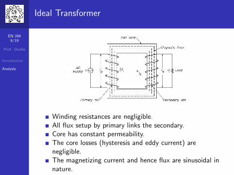
Ideal Transformer
Winding resistances are negligible.All flux setup by primary links the secondary.Core has constant permeability.The core losses (hysteresis and eddy current) arenegligible.The magnetizing current and hence flux are sinusoidal innature.

EN 20610/19
Prof. Doolla
Introduction
Analysis
Ideal Transformer- EMF Generation
EMF inducted in the primary e1 = −N1dφdt
If we assume that the flux is sinusoidal in nature(φ = φmsinωt), then:e1 = −N1ωφmcosωt = N1ωφmsin(ωt − π
2 )
Rms value of e1 = E1 =E1,max√
2= N1ωφm√
2=√
2πfN1φm
EMF inducted in the secondarye1 = −N2
dφdt = −N2ωφmcosωt = E2maxsin(ωt − π
2 )
Rms value of e2 = E2 =E2,max√
2= N2ωφm√
2=√
2πfN2φm
∴ E1E2
= N1N2
, also E1N1
= E2N2
=√
2πfN2φm, i.e, emf per turn inprimary is equal to emf per turn in secondary.
EN 20611/19
Prof. Doolla
Introduction
Analysis
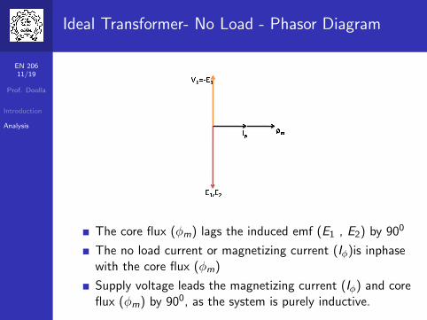
Ideal Transformer- No Load - Phasor Diagram
The core flux (φm) lags the induced emf (E1 , E2) by 900
The no load current or magnetizing current (Iφ)is inphasewith the core flux (φm)
Supply voltage leads the magnetizing current (Iφ) and coreflux (φm) by 900, as the system is purely inductive.

EN 20612/19
Prof. Doolla
Introduction
Analysis
Ideal Transformer- Phasor Diagram - Secondaryloaded
When the secondary circuit is loaded, secondary mmfbeing opposite to φm, tends to reduce the alternatingmutual flux φm.
For an ideal transformer |E1| = |V1|, as the supply voltageremains constant, therefore more amount of power isdrawn from primary.
Compensating primary mmf = Secondary mmf i.e.,I′1N1 = I2N2, where I
′1 is load component of primary
current I1.

EN 20613/19
Prof. Doolla
Introduction
Analysis
Ideal Transformer- Phasor Diagram - Secondaryloaded
The total primary current I1 is the phasor sum of I′1 and Iφ.
I1 = I′1 + Iφ
Power factor of the system is given by cosφ
If Iφ is neglected, I1N1 = I2N2 =⇒ E1E2
= N1N2
= I2I1
= V1V2
Total input power = Total output power =⇒ V1I1 = V2I2

EN 20614/19
Prof. Doolla
Introduction
Analysis
Impedance Transformation
Used to simplify the equivalent circuit
If Z2 is impedance of load connected, V2 is the voltage ofsecondary, I2 is current through the secondary winding,then Z2 = V2
I2,
Also, V1N1
= V2N2
; I1N1 = I2N2
If the secondary impedance is transferred to primary side,then impedance seen by primary circuit is given by:V1I1
= N1N2V2 × N1
N2
1I2
=⇒ V1I1
= Z′2 = (N1
N2)2Z2
Similarly, when primary impedance is referred tosecondary, Z
′1 = (N2
N1)2Z1

EN 20615/19
Prof. Doolla
Introduction
Analysis
Phasor Diagram - No Load
α: Hysteresis angle, Ie : excitingcurrent, Iφ : Magnetizingcurrent, Ic : Core loss component
r1: primary resistance
x1: fictituous quantityintroduced to represent theleakage flux in primary
Primary leakage impedance dropis about 2 to 5% even at fullload.
The magnetizing current istypically 1% of full load currentand hence is neglected.

EN 20616/19
Prof. Doolla
Introduction
Analysis
Phasor Diagram - Lagging Load
θ1 and θ2 is the power factor ofthe load and source respectively.
r1: primary resistance
x1: fictituous quantityintroduced to represent theleakage flux in primary
Primary leakage impedance dropis about 2 to 5% even at fullload.
Phasor diagram is helpful only:
When a transformer is to bestudied aloneWhen the internal behaviour ofthe transformer is to beunderstood
EN 20617/19
Prof. Doolla
Introduction
Analysis
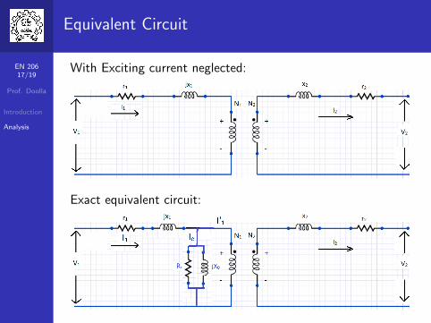
Equivalent Circuit
With Exciting current neglected:
Exact equivalent circuit:

EN 20618/19
Prof. Doolla
Introduction
Analysis
Equivalent Circuit
Equivalent circuit referred to primary:

EN 20619/19
Prof. Doolla
Introduction
Analysis
Summary
Transformers
Principle of operationEquivalent Circuit
Next ClassTesting of TransformerAuto Transformer
Thank you!!
For Further Reading:
Transformer Engineering: Design and Practice Authors:S.V. Kulkarni and S.A. Khaparde Publisher: MarcelDekker (Taylor & Francis Group), New York, May 2004ISBN: 0-8247-5653-3
Electric Machinery: A. E. Fitzgerald, C. Kingsley, S. D.Umans. Publisher: TMH, New Delhi, India, 2009