Embed Size (px)
Citation preview
EUROPEAN STANDARD
NORME EUROPÉENNE
EUROPÄISCHE NORM
EN 14800
March 2007
ICS 23.040.70
English Version
Corrugated safety metal hose assemblies for the connectiondomestic appliance using gaseous fuels
Tuyaux flexibles métalliques onduleux de securité pour leraccordement d'appareils à usage domestique utilisant des
gaz combustibles
Gewellte, metallene Sicherheits-Gasschlauchleitungen fürden Anschluss von Haushalts-Gasgeräten
This European Standard was approved by CEN on 6 December 2006.
CEN members are bound to comply with the CEN/CENELEC Internal Regulations which stipulate the conditions for giving this EuropeanStandard the status of a national standard without any alteration. Up-to-date lists and bibliographical references concerning such nationalstandards may be obtained on application to the CEN Management Centre or to any CEN member.
This European Standard exists in three official versions (English, French, German). A version in any other language made by translationunder the responsibility of a CEN member into its own language and notified to the CEN Management Centre has the same status as theofficial versions.
CEN members are the national standards bodies of Austria, Belgium, Bulgaria, Cyprus, Czech Republic, Denmark, Estonia, Finland,France, Germany, Greece, Hungary, Iceland, Ireland, Italy, Latvia, Lithuania, Luxembourg, Malta, Netherlands, Norway, Poland, Portugal,Romania, Slovakia, Slovenia, Spain, Sweden, Switzerland and United Kingdom.
EUROPEAN COMMITTEE FOR STANDARDIZATIONC OM ITÉ EUR OP ÉEN DE NOR M ALIS AT IONEUROPÄISCHES KOMITEE FÜR NORMUNG
Management Centre: rue de Stassart, 36 B-1050 Brussels
© 2007 CEN All rights of exploitation in any form and by any means reservedworldwide for CEN national Members.
Ref. No. EN 14800:2007: E
Standard is proposed to be implemented as HST standardSARMCopying and networking prohibited.

EN 14800:2007 (E)
2
Contents Page
Foreword..............................................................................................................................................................5 Introduction .........................................................................................................................................................6 1 Scope ......................................................................................................................................................7 2 Normative references ............................................................................................................................7 3 Terms and definitions ...........................................................................................................................8 4 Construction requirements...................................................................................................................9 4.1 General....................................................................................................................................................9 4.2 Nominal size .........................................................................................................................................10 4.3 Materials ...............................................................................................................................................10 4.4 Requirements for the connection between hose and fittings.........................................................10 4.5 End fittings design requirements.......................................................................................................10 4.6 CMG hose assembly lengths..............................................................................................................11 4.7 Corrosion requirements......................................................................................................................11 4.8 Insulation requirements ......................................................................................................................11 4.9 Electric conductivity requirements....................................................................................................11 4.10 Hygiene .................................................................................................................................................11 4.11 Cover materials ....................................................................................................................................11 4.12 Dangerous substances .......................................................................................................................11 5 Performance requirements and tests ................................................................................................12 5.1 General..................................................................................................................................................12 5.2 Test sequence schedule .....................................................................................................................12 5.3 Leak-tightness......................................................................................................................................14 5.3.1 Requirements .......................................................................................................................................14 5.3.2 Test procedure .....................................................................................................................................14 5.4 Structural strength...............................................................................................................................14 5.4.1 Requirements .......................................................................................................................................14 5.4.2 Test procedure .....................................................................................................................................14 5.5 Flow rate ...............................................................................................................................................14 5.5.1 Requirements .......................................................................................................................................14 5.5.2 Test procedure .....................................................................................................................................15 5.5.3 Conversion of air flow rate .................................................................................................................17 5.6 Electric continuity................................................................................................................................18 5.6.1 Requirements .......................................................................................................................................18 5.6.2 Test procedure .....................................................................................................................................18 5.7 Tension .................................................................................................................................................18 5.7.1 Requirements .......................................................................................................................................18 5.7.2 Test procedure .....................................................................................................................................18 5.8 Durability of marking...........................................................................................................................19 5.8.1 Requirements .......................................................................................................................................19 5.8.2 Test procedure .....................................................................................................................................19 5.9 Working temperature...........................................................................................................................20 5.9.1 Requirements .......................................................................................................................................20 5.9.2 Test procedure .....................................................................................................................................20 5.10 Corrosion resistance...........................................................................................................................20 5.10.1 Requirements .......................................................................................................................................20 5.10.2 Test procedure .....................................................................................................................................20
Standard is proposed to be implemented as HST standardSARMCopying and networking prohibited.

EN 14800:2007 (E)
3
5.11 Reaction to fire ....................................................................................................................................21 5.11.1 Requirements.......................................................................................................................................21 5.11.2 Testing and assessment methods.....................................................................................................21 5.12 Resistance to high temperature.........................................................................................................22 5.12.1 Requirements.......................................................................................................................................22 5.12.2 Test procedure.....................................................................................................................................22 5.13 Suppleness ..........................................................................................................................................22 5.13.1 Requirements.......................................................................................................................................22 5.13.2 Test procedure.....................................................................................................................................22 5.14 Bending performance .........................................................................................................................22 5.14.1 Bending performance for type 1 hoses with non-restricted bend radius .....................................22 5.14.2 Bending performance for type 2 hoses having a restricted bend radius......................................24 5.15 Flexing resistance ...............................................................................................................................25 5.15.1 Requirements.......................................................................................................................................25 5.15.2 Test procedure.....................................................................................................................................25 5.16 Torsion resistance...............................................................................................................................26 5.16.1 Requirements.......................................................................................................................................26 5.16.2 Test procedure.....................................................................................................................................27 5.17 Impact/crushing resistance................................................................................................................27 5.17.1 Requirements.......................................................................................................................................27 5.17.2 Test procedure.....................................................................................................................................28 5.18 Penetration resistance ........................................................................................................................28 5.18.1 Requirements.......................................................................................................................................28 5.18.2 Test method .........................................................................................................................................28 5.19 End fittings...........................................................................................................................................29 5.19.1 Requirements.......................................................................................................................................29 5.19.2 Test procedures...................................................................................................................................29 5.19.3 End fittings bodies manufactured from more than one part ..........................................................30 6 Evaluation of conformity ....................................................................................................................31 6.1 General .................................................................................................................................................31 6.2 Type testing .........................................................................................................................................31 6.2.1 Initial type testing ................................................................................................................................31 6.2.2 Subsequent type testing.....................................................................................................................32 6.3 Factory production control (FPC)......................................................................................................32 6.3.1 General .................................................................................................................................................32 6.3.2 FPC requirements for all manufacturers...........................................................................................32 6.3.3 Manufacturer-specific FPC system requirements ...........................................................................34 6.4 Installation instruction ........................................................................................................................35 6.5 Packaging.............................................................................................................................................36 Annex A (informative) Hose fitting design requirements for connection to the gas supply
pipework, to the pressure reduction device of portable gas bottles or to domestic appliance ..............................................................................................................................................37
Annex B (normative) Thermal attack by a single burning item....................................................................53 B.1 General .................................................................................................................................................53 B.2 Scope ....................................................................................................................................................54 B.3 Standardized mounting and fixing ....................................................................................................54 Annex C (normative) Single-flame source test ..............................................................................................55 C.1 General .................................................................................................................................................55 C.2 Scope ....................................................................................................................................................55 C.3 Standardized mounting and fixing ....................................................................................................56 C.4 Test definition ......................................................................................................................................56 C.5 Test duration........................................................................................................................................56 Annex ZA (informative) Clauses of this EN addressing the provisions of EU Construction
Products Directive...............................................................................................................................57 ZA.1 Scope and relevant characteristics ...................................................................................................57
Standard is proposed to be implemented as HST standardSARMCopying and networking prohibited.

EN 14800:2007 (E)
4
ZA.2 Procedure for attestation of conformity of corrugated safety metal hose assemblies..................59 ZA.2.1 Systems of attestation of conformity ................................................................................................59 ZA.2.2 EC Certificate and Declaration of conformity ...................................................................................61 ZA.3 CE Marking and labelling ....................................................................................................................62 Bibliography ......................................................................................................................................................66
Standard is proposed to be implemented as HST standardSARMCopying and networking prohibited.

EN 14800:2007 (E)
5
Foreword
This document (EN 14800:2007) has been prepared by Technical Committee CEN/TC 236 “Non industrial manually operated shut-off valves for gas and particular combinations valves-other products”, the secretariat of which is held by UNI.
This European Standard shall be given the status of a national standard, either by publication of an identical text or by endorsement, at the latest by September 2007, and conflicting national standards shall be withdrawn at the latest by December 2008.
This document has been prepared under a mandate given to CEN by the European Commission and the European Free Trade Association, and supports essential requirements of EU Directive 89/106/EC.
For relationship with EU Directive(s), see informative Annex ZA, which is an integral part of this document.
For corrugated metal gas hose assemblies pre-installed to a gas appliance and put on the market as one unit the Gas Appliance Directive is applicable. Additional requirements may apply.
According to the CEN/CENELEC Internal Regulations, the national standards organizations of the following countries are bound to implement this European Standard: Austria, Belgium, Bulgaria, Cyprus, Czech Republic, Denmark, Estonia, Finland, France, Germany, Greece, Hungary, Iceland, Ireland, Italy, Latvia, Lithuania, Luxembourg, Malta, Netherlands, Norway, Poland, Portugal, Romania, Slovakia, Slovenia, Spain, Sweden, Switzerland and United Kingdom.
Standard is proposed to be implemented as HST standardSARMCopying and networking prohibited.

EN 14800:2007 (E)
6
Introduction
This European Standard contains product characteristics relating to the safety of persons, animal and property and the protection of their environment.
The objective of this European Standard is to achieve safe operation of corrugated metal gas hose assemblies by specifying the requirements of performance, materials and test methods.
These assemblies are designed for the use with fixed applications; they may also be used for the connection of movable applications.
This European Standard is based on a balance of requirements given by the major national European Gas Authorities for corrugated metal hose assemblies for the connection of domestic gas appliances.
It reflects the recognised practise and technology of products approved today as well as the present culture of usage by the consumer.
The European Standard describes two product types, one with an unrestricted bending radius and one with a restricted bending radius.
The introduction of new technologies supported by National Gas Authorities can require the adoption of this European Standard regarding individual requirements and tests.
Attention is drawn to the need for careful quality control as given in EN ISO 9001.
Standard is proposed to be implemented as HST standardSARMCopying and networking prohibited.
EN 14800:2007 (E)
7
1 Scope
This European Standard specifies the requirements of performance, the material and the test methods of corrugated safety metal gas hose assemblies for the connection of domestic appliances, in order to achieve save operation.
The corrugated metal gas hose assemblies according to this European Standard are suitable for the connection of domestic appliances inside or outside a dwelling, using gas at a pressure lower than 0,5 bar.
2 Normative references
The following referenced documents are indispensable for the application of this document. For dated references, only the edition cited applies. For undated references, the latest edition of the referenced document (including any amendments) applies.
EN 437:2003, Test gases — Test pressures — Appliance categories
EN 549, Rubber materials for seals and diaphragms for gas appliances and gas equipment
EN 1418, Welding personnel — Approval testing of welding operators for fusion welding and resistance weld setters for fully mechanized and automatic welding of metallic materials
EN 1775:1998, Gas supply — Gas pipework for buildings — Maximum operating pressure ≤ 5 bar — Functional recommendations
EN 13133, Brazing — Brazer approval
EN 13134, Brazing — Procedure approval
EN 13501-1:2006, Fire classification of construction products and building elements — Part 1: Classification using test data from reaction to fire tests
EN 13823, Reaction to fire tests for building products — Building products excluding floorings exposed to the thermal attack by a single burning item
prEN 15069:2004, Safety gas connection valves for metal hose assemblies used for the connection of domestic appliances using gaseous fuel
EN ISO 9001:2000, Quality management systems — Requirements (ISO 9001:2000)
EN ISO 9227, Corrosion tests in artificial atmospheres — Salt spray tests (ISO 9227:2006)
EN ISO 10380, Pipework — Corrugated metal hoses and hose assemblies (ISO 10380:2003)
EN ISO 11925-2, Reaction to fire tests — Ignitability of building products subjected to direct impingement of flame — Part 2: Single-flame source test (ISO 11925-2:2002)
Standard is proposed to be implemented as HST standardSARMCopying and networking prohibited.
EN 14800:2007 (E)
8
3 Terms and definitions
For the purposes of this document, the following terms and definitions apply.
3.1 domestic appliance appliance intended for use by individual householders inside or outside a dwelling
3.2 corrugated safety metal gas hose assembly element of flexible pipe-work to be fitted between the gas supply valve or the socket of a quick disconnect device and the appliance inlet connection, consisting of a corrugated metal hose, its end fittings with appropriate gaskets and, if required, an armouring and/or an external protection
3.3 CMG hose assembly abbreviation used in this European Standard to denote a corrugated safety metal gas hose assembly as defined in 3.2
3.4 corrugated metal hose pressure-tight hose made from tube or from welded strip with corrugations, helicoidal or annular to the axis of the hose, made by deforming the metal
3.5 end fittings components attached to a metal hose so as to constitute a metal hose assembly
3.6 screwed connection leak-tight threaded connection, which can only be assembled and disassembled with an appropriate tool
3.7 integrated non-detachable fitting end fitting, permanently attached to the corrugated metal hose by such a method as welding or brazing, so as to ensure that it can not be detached without destruction or alteration
3.8 safety quick connection device end fitting consisting of two parts that is designed to permit quick connection and disconnection without tools, leak-tight so that it prevents the release of gas from the upstream pipe work when disconnected and designed to prevent accidental disconnection and incorrect operation
3.9 armouring external reinforcement, partly or wholly covering the corrugated metal hose, which is designed to improve the mechanical characteristics of the hose
3.10 external protection outer cover used to protect the hose from environmental and other outside influences
Standard is proposed to be implemented as HST standardSARMCopying and networking prohibited.

EN 14800:2007 (E)
9
3.11 nominal length length of a CMG hose assembly measured along its axis, including its end fittings, but excluding any swivel nuts.
CMG hose assemblies incorporating the plug of a quick connection device are measured to the point where the plug enters the socket in the working position
3.12 non-restricted bending radius radius measured to the centre line of the hose
3.13 restricted bending radius bending radius, which by the use of an additional component is limited to a minimum value measured to the centre line of the hose.
A lower value can only be reached by permanently deforming or destroying the additional component
3.14 rated flow-rate flow rate, under standard reference conditions, at a given pressure drop
3.15 seal gasket non metallic element assuring leak-tightness between two adjacent elements, be they fixed or moveable in respect to each other
3.16 swivel joint rotary joint element or device that enables a continuous axial rotation of the hose with respect to the gas inlet or the appliance, and which functions without reducing the leak-tightness of the flexible connection
3.17 gas first, second and third family gas as referred to in EN 437:2003, Table 1.
These gases are commonly referred to as manufactured gases, natural gases or liquefied petroleum gases (LPG)
4 Construction requirements
4.1 General
These requirements shall ensure that the construction of a CMG hose assembly which, when properly installed and correctly used, under normal chemical, mechanical and thermal conditions will provide long term safe operation without degradation.
CMG hose assemblies are subdivided into:
type 1: CMG hose assemblies having no additional component limiting their bending radii;
type 2: CMG hose assemblies having an additional component limiting their bending radii.
Standard is proposed to be implemented as HST standardSARMCopying and networking prohibited.

EN 14800:2007 (E)
10
4.2 Nominal size
The nominal size of CMG hose assemblies shall be designated either DN 8 or DN 12 and shall be determined by the flow rate requirements given in Table 2. For the purpose of this European Standard, DN 10 and DN 15 fittings shown in Annex A are considered as DN 8 and DN 12 respectively.
4.3 Materials
The CMG hose assembly described by this European Standard shall be manufactured from materials which shall withstand the performance and test requirements given in Clause 5. The corrugated metal hose shall be manufactured from metal(s) no less durable and robust than stabilized austenitic stainless steel and fulfil in addition to the requirements of this European Standard the requirements of EN ISO 10380. End fittings and non-permanently attached parts, whether surface finished or not, shall be manufactured from stainless steel, or from copper alloys containing at least 57 % copper and up to 3,5 % lead.
Where there may be risk of stress corrosion cracking, any threaded parts manufactured from the above copper alloys shall be stress relieved.
4.4 Requirements for the connection between hose and fittings
The connection between the corrugated hose and the end fitting of a CMG hose assembly as defined by this European Standard shall be made by a method such as welding or brazing, resulting in an integrated non-detachable connection, which can only be detached by irreparably damaging the hose or the end fitting. The connection shall ensure leak-tightness and shall withstand all tests requested in Clause 5. Welding and brazing processes shall conform to EN 1418, EN 13134 and EN 13133.
It shall be possible to withdraw swivel nuts in order to free the sealing surface.
4.5 End fittings design requirements
End fittings shall be manufactured from materials that permit the CMG assembly to comply with the performance requirements of this European Standard for a reasonable economic working life when tested according to Table 1.
The design of end fittings shall be in accordance with 5.19.
A CMG hose assembly shall be fitted either with a swivel nut on one end and or a swivel joint.
The design of swivel nuts shall ensure that when used in conjunction with its seal/gasket and its matching part tightness is achieved at a maximum torque of (10 ± 0,5) N ⋅ m and that when further tightened to an torque of (50 ± 2,5) N ⋅ m there shall be no visible deformation or cracking and the connection shall remain gas tight.
Fittings used in conjunction with swivel nuts shall incorporate a means to hold the fitting during the tightening of the swivel nut without applying torsion to the hose or damage to the fitting.
Where threads are used at both ends of an assembly and there is a possibility of the assembly being installed the wrong way round, the fittings shall be identified by different colours and the flow direction shall be marked by the use of an arrow.
Seals/gaskets shall be from material suitable for their intended application. They shall be designed to be reusable and shall be retained on the fitting or held in place by caps and shall comply with the requirements of EN 549.
Screwed connections shall be capable of being assembled and disassembled only by using an appropriate tool without visible damage to the fitting.
Standard is proposed to be implemented as HST standardSARMCopying and networking prohibited.

EN 14800:2007 (E)
11
4.6 CMG hose assembly lengths
The normal nominal lengths of the CMG hose assemblies shall be 0,5 m, 0,75 m, 1,0 m, 1,25 m, 1,5 m and 2,0 m. The admissible length tolerance shall be ± 20 mm. The maximum nominal length of a CMG hose assembly shall be 2,0 m.
NOTE CMG hose assemblies according to this European Standard are not designed to be joined together to form a hose string.
4.7 Corrosion requirements
CMG hose assemblies shall be resistant to any corrosive agents reasonably foreseen in a domestic environment.
NOTE If required the corrosion resistance of a CMG hose assembly can be increased by some form of external protection.
4.8 Insulation requirements
The corrugated metal hose part of a CMG hose assembly shall be electrically insulated externally by the use of an appropriate synthetic material at potential points of contact with metallic elements where cathodic corrosion can take place.
4.9 Electric conductivity requirements
CMG hose assemblies shall be electrically continuous along their length.
4.10 Hygiene
CMG hose assemblies shall have an outer surface, which can be readily cleaned by normal household means.
4.11 Cover materials
If the materials of a synthetic cover contain corrosive agents as ingredients, such as sulphur or chlorine, care shall be taken to ensure that such agents are not released during the manufacturing process.
4.12 Dangerous substances
Materials used in CMG hose assemblies shall not release any dangerous substances in excess of the maximum permitted levels specified in a relevant European Standard for the material or permitted in the national regulations of the member state of destination.
Standard is proposed to be implemented as HST standardSARMCopying and networking prohibited.
EN 14800:2007 (E)
12
5 Performance requirements and tests
5.1 General
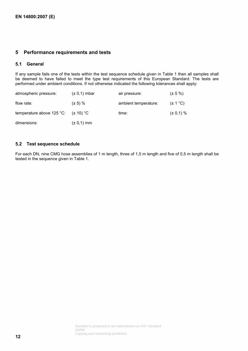
If any sample fails one of the tests within the test sequence schedule given in Table 1 then all samples shall be deemed to have failed to meet the type test requirements of this European Standard. The tests are performed under ambient conditions. If not otherwise indicated the following tolerances shall apply:
atmospheric pressure: (± 0,1) mbar air pressure: (± 5 %)
flow rate: (± 5) % ambient temperature: (± 1 °C)
temperature above 125 °C: (± 10) °C time: (± 0,1) %
dimensions: (± 0,1) mm
5.2 Test sequence schedule
For each DN, nine CMG hose assemblies of 1 m length, three of 1,5 m length and five of 0,5 m length shall be tested in the sequence given in Table 1.
Standard is proposed to be implemented as HST standardSARMCopying and networking prohibited.

EN 14800:2007 (E)
13
Table 1 — Test sequence schedule
Hose assembly No 1 2 3 4 5 6 7 8 9 10 to 15
16 17 No of samples
Hose length in metres 1,0 1,0 1,0 1,0 1,0 1,0 1,0 1,0 1,0 0,5 + 1,5
0,5 0,5
Initial leak-tightness test 5.3.2 X X X X X X X X X X X X 17
Structural strength test 5.4.2 X 1
Flow rate test 5.5.2 X 1
Electrical continuity test 5.6.2 X 1
Tension test 5.7.2 X 1
Durability of marking test 5.8.2 X 1
Working temperature test 5.9.2 X X 2
Salt spray test 5.10.2.1 X 1
Hydrochloric acid test 5.10.2.2 X 1
Household cleaning agent test
5.10.2.3 X 1
Reaction to fire 5.11.2 X 3 +3
Fire resistance test 5.12.2 X 1
Suppleness test 5.13.2 X 1
Bending test non-restricted bend radius
or
Bending test restricted bend radius
5.14.1.2
5.14.2.2
X
X
X
3
Flexing test 5.15.2 X X X 3
Torsion test 5.16.2 X 1
Impact resistance test 5.17.2 X 1
Penetration test 5.18.2 X
Fitting tests where requested 5.19
Drop test 5.19.2.1 X 1
Crush test 5.19.2.2 X 1
Torque test 5.19.3.2 X 1
Final leak-tightness test 5.3.2 X X X X X X X X X X 10
Standard is proposed to be implemented as HST standardSARMCopying and networking prohibited.

EN 14800:2007 (E)
14
5.3 Leak-tightness
5.3.1 Requirements
The CMG hose assembly shall be leak-tight when tested in accordance with the methods given in 5.3.2.
In the initial leak-tightness test any external protection shall remain in place. In the final leak-tightness test it shall be demonstrated that any external protection does not contribute to the achievement of the given leakage rate.
The verification of gas leak-tightness after installation of the CMG hose assembly and its connecting parts shall be in accordance with the manufacturer’s installation instruction.
Leak-tightness requirements between a CMG hose assembly and its safety quick connection device shall be as prEN 15069:2004, 5.4.
5.3.2 Test procedure
When held under water and containing air at a pressure of 3 bar the leakage rate of the CMG hose assembly shall not exceed 10 cm3/h.
NOTE A leakage rate not exceeding (7 × 10⁻³) mbar l/sec is equivalent to the above requirement.
In the final leak-tightness test for type testing it shall be verified that any external protection has not contributed to the achievement of the above leakage rate by cutting open a cover with at least 3 cuts of 20 mm equally spaced along the length of the hose.
5.4 Structural strength
5.4.1 Requirements
A CMG hose assembly shall have a structural strength capable of resisting any environmental mechanical influence reasonably foreseen. This shall be regarded as being equivalent to withstanding an internal pressure of 6 bar.
5.4.2 Test procedure
The length of the CMG hose assemblyshall be measured on a flat surface and recorded. The CMG hose assembly, one of its ends being free to move, shall be gradually pressurised up to 6 bar. This pressure shall be maintained for at least 5 min.
The permanent elongation of the CMG hose assembly after release of pressure shall not exceed 3 % of its length before pressurisation. With the exception of the permanent elongation, no visual deformation of the corrugated hose or any other part of the assembly shall be permitted.
Following the test the CMG hose assembly shall be subjected to the leak-tightness test given in 5.3.2.
5.5 Flow rate
5.5.1 Requirements
The minimum flow rate through a CMG hose assembly without the valve and when tested as follows shall be as given in Table 2.
Standard is proposed to be implemented as HST standardSARMCopying and networking prohibited.

EN 14800:2007 (E)
15
The flow rate shall be determined using dry air at a pressure of 20 mbar at the given pressure drop in Table 2. Measurement shall be converted to standard conditions of a pressure of 1 013,25 mbar and a temperature of 15 °C.
Table 2 — Flow rate requirements
Nominal size of hose assembly
Overall length of hose assembly
Minimum air flow rate for gases other than Type L with a pressure drop of
1 mbar
Minimum air flow rate for gas Type L with a pressure
drop of 0,5 mbar
DN 8 1,0 m 0,5 m3/h 0,55 m³/h
DN 12 1,0 m 1,5 m3/h 1,2 m³/h
The power equivalent of the gas flowing through a CMG hose assembly is also influenced by the hose length and the type of the gas family. The manufacturer shall indicate for each length the minimum power rating relating to the individual gas family.
NOTE Type L gas is a low calorific gas as defined in EN 437:2003, Table 1.
5.5.2 Test procedure
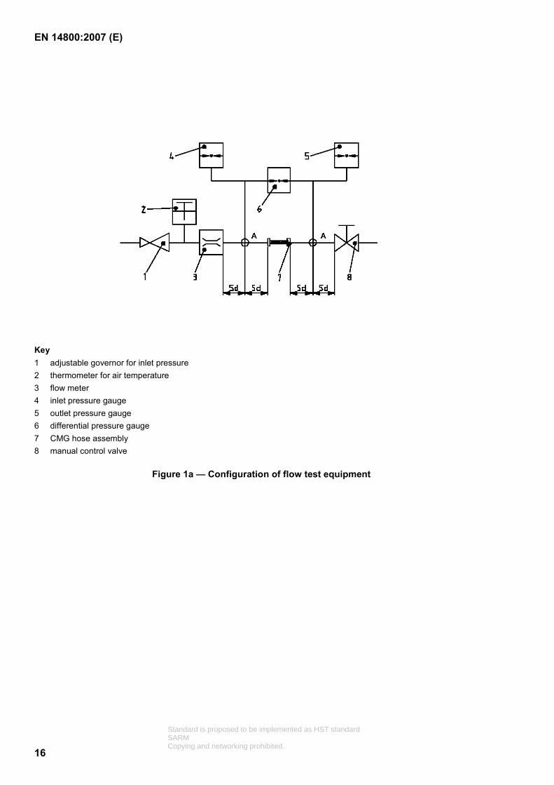
Air shall be supplied at constant pressure to a positive displacement differential meter of suitable range, having an error not greater than 5 % of the rate to be measured. The air shall be passed at a pressure of 20 mbar, through a straight length of pipe connected directly to the inlet of the CMG hose assembly, see Figure 1a. Any additional pressure drop created by adapters fitted to the CMG hose assembly shall be deducted from the measured value.
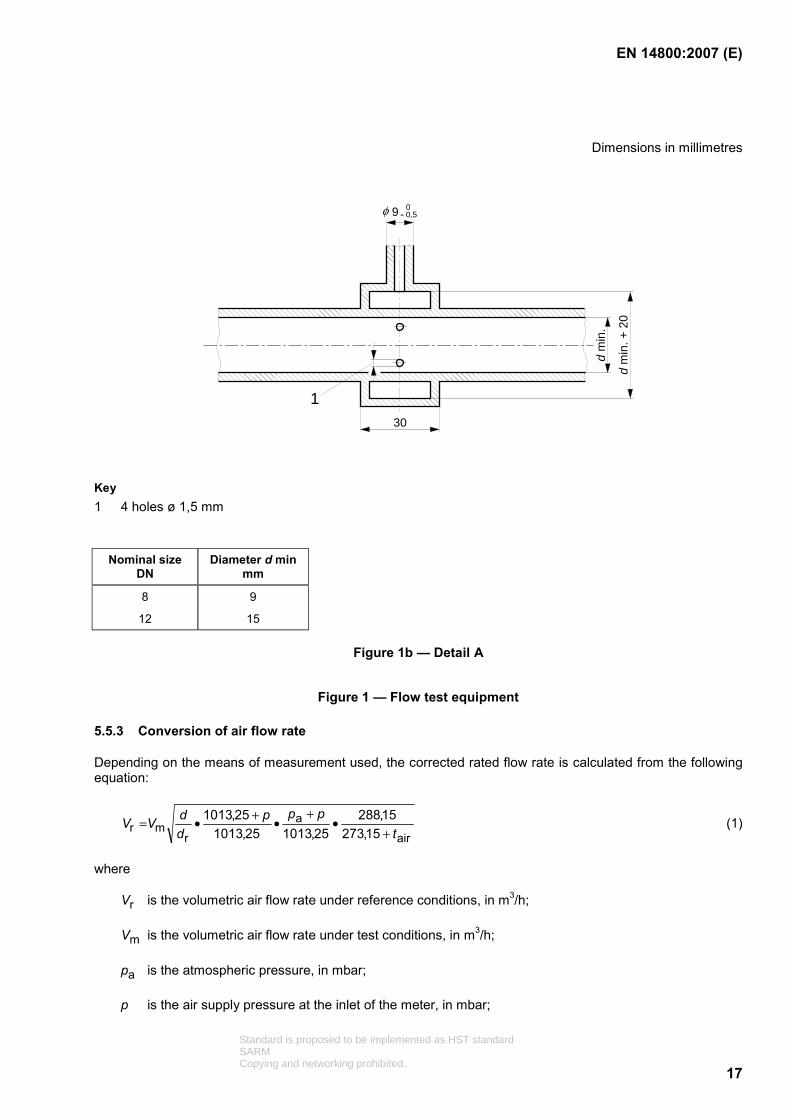
The pipe shall have a bore size as given in Figure 1b, detail A, and is to be at least 10 pipe diameters in length with a pressure tapping five diameters upstream of the hose assembly. Another pressure tapping is positioned five pipe diameters downstream of the hose assembly on a similar pipe, which is also of at least 10 diameters in length. A differential pressure gauge capable of being read directly to 0,05 mbar or less is connected as shown in Figure 1a.
The air flow rate is adjusted by means of a control valve on the outlet of the pipe to give the required differential pressure across the CMG hose assembly and the air temperature is maintained to ± 0,5 °C. The flow rate shall be recorded and corrected to standard conditions of 1 013,25 mbar and 15 °C.
If the hose has an end fitting which incorporates features that are part of a quick connection device, and those features impair the flow, they may be eliminated for the purposes of this test.
NOTE The flow rate of an end fitting which forms part of a safety quick connection device is tested as part of the quick connection device under the requirements of prEN 15069.
Standard is proposed to be implemented as HST standardSARMCopying and networking prohibited.
EN 14800:2007 (E)
16
Key 1 adjustable governor for inlet pressure 2 thermometer for air temperature 3 flow meter 4 inlet pressure gauge 5 outlet pressure gauge 6 differential pressure gauge 7 CMG hose assembly 8 manual control valve
Figure 1a — Configuration of flow test equipment
Standard is proposed to be implemented as HST standardSARMCopying and networking prohibited.
EN 14800:2007 (E)
17
Dimensions in millimetres
d m
in.
d m
in. +
20
30
9 00,5-φ
1
Key 1 4 holes ø 1,5 mm
Nominal size DN
Diameter d min mm
8 9
12 15
Figure 1b — Detail A
Figure 1 — Flow test equipment
5.5.3 Conversion of air flow rate
Depending on the means of measurement used, the corrected rated flow rate is calculated from the following equation:
air
a
rmr 15,273
15,28825,101325,1013
25,1013t
pppddVV
+•
+•+•= (1)
where
Vr is the volumetric air flow rate under reference conditions, in m3/h;
Vm is the volumetric air flow rate under test conditions, in m3/h;
pa is the atmospheric pressure, in mbar;
p is the air supply pressure at the inlet of the meter, in mbar;
Standard is proposed to be implemented as HST standardSARMCopying and networking prohibited.
EN 14800:2007 (E)
18
tair is the air temperature at the measuring point, in °C;
d is the density of air used (e.g. if a wet meter is used);
dr is the dry air density.
If a dry meter is used, the ratio 1r
=dd .
5.6 Electric continuity
5.6.1 Requirements
The CMG hose assembly shall be electrically continuous. The electric resistance of an installed hose assembly shall not exceed 1 Ω/m.
5.6.2 Test procedure
A CMG hose assembly of 1 m nominal length shall be connected between copper dummy fittings representative of the gas inlet and appliance connection. These dummy fittings shall be connected for a maximum of 1 min to an alternating current of 25 A supplied by a generator whose open circuit voltage does not exceed 12 V.
The voltage drop shall be measured between the dummy fittings and the electric resistance shall be calculated from the voltage drop and the related current. The resistance shall not exceed 1 Ω/m, measured with an accuracy of ± 2 %. The electric resistance of the electric cables shall not be included in the measurement.
5.7 Tension
5.7.1 Requirements
A CMG hose assembly shall withstand an axial tension of 1 000 N without leakage. When under this load the assembly length shall not increase by more than 10 %. After release of the load the permanent elongation shall not exceed more than 3 % of the original length and the assembly shall meet the requirements of 5.3.1.
5.7.2 Test procedure
The CMG hose assembly, including its cover if fitted, shall be attached at one end by its end fitting to a fixed support. The other end shall be fixed to a movable part, which moves in the axis of the hose assembly. The CMG hose assembly shall be put under tension until the value of 1 000 N is reached. The test rig shall have a feed rate of (100 ± 5) mm/min. The tension value of 1 000 N shall be maintained for 5 min.
CMG hose assemblies incorporating quick connection fittings shall be attached with the quick connection at the fixed support of the test fixture. Such attachment shall be of the same kind as used in service and the quick connection valve shall be in its open position.
During the test the CMG hose assembly length shall not increase more than 10 %.
After the test upon visual examination there shall be no deterioration, the permanent elongation shall not exceed 3 % and the CMG hose assembly shall pass the leak-tightness test given in 5.3.1.
Standard is proposed to be implemented as HST standardSARMCopying and networking prohibited.

EN 14800:2007 (E)
19
5.8 Durability of marking
5.8.1 Requirements
The marking on the CMG hose assembly shall be permanent and withstand normal usage and wear. If not mechanically impressed or etched in the metal parts belonging to the structure of the CMG hose assembly, it shall withstand the test procedure as described under 5.8.2.
5.8.2 Test procedure
A piece of cotton cloth is fixed to the end of a 16 mm diameter cylindrical slide as shown in Figure 2 in such a way that it can be slid over the marking under a vertical load of ( )1
09+ N.
The cotton cloth prepared as given below is slid 10 times back and forth over a length of 100 mm of the marking on the CMG hose assembly, resulting in a total of 20 friction movements.
The test shall be first performed with a dry cotton cloth and followed with a cotton cloth wetted with de-mineralised water and for both tests it shall be performed on the same place, resulting in a total of 40 friction movements. The wetted cotton cloth shall have double the weight of the dry cotton cloth.
The cotton cloth utilised for this test shall have a smooth surface and be of light weight. Following the above procedure each and every character shall be readable.
Dimensions in millimetres
1
22
3
54
Key 1 hose fixing 2 slide 3 Movable cylinder 4 hose 5 cotton cloth
Figure 2 — Details of the durability of marking test rig
Standard is proposed to be implemented as HST standardSARMCopying and networking prohibited.
EN 14800:2007 (E)
20
5.9 Working temperature
5.9.1 Requirements
A CMG hose assembly shall be designed and constructed so it can safely operate in the ambient temperatures experienced inside and outside of a dwelling.
5.9.2 Test procedure
A CMG hose assembly complete with its cover if fitted shall be placed in an oven at 120 °C ± 2 °C for 72 h. The assembly shall then be removed, allowed to cool to room temperature, and subjected to a visual examination. There shall be no visible cracking or deterioration other than a change of colour of the cover and plastic parts.
5.10 Corrosion resistance
5.10.1 Requirements
Following the corrosion tests given in 5.10.2 the CMG hose assembly shall show no visual sign of corrosion or other deterioration, which may reasonably be expected to influence the safe performance of the product.
Covers if fitted shall be liquid tight in order to prevent penetration of liquid under the cover and onto the corrugated hose.
5.10.2 Test procedure
5.10.2.1 Salt spray test
A CMG hose assembly of 1 m length, complete with its cover if fitted shall be placed in a salt spray test chamber conforming to EN ISO 9227. The CMG hose assembly is not under pressure. Caps shall close the CMG hose assembly. The test chamber shall spray a saline solution having a mass concentration of 5 % (± 0,5 %) sodium chloride in distilled water. The intensity of the spray shall be such that, for each 80 cm2 of the horizontal collecting surface, 2 ml (± 1 ml) of solution are collected per hour.
The test chamber shall be maintained at a temperature of 35 °C (± 1 °C). The test shall last 96 h (± 2 h).
This test shall immediately be followed by the test given in 5.10.2.2. The test result shall be analysed after both tests are performed.
5.10.2.2 Hydrochloric acid test
A CMG hose assembly of 1 m length, complete with any external cover if fitted, shall be plugged, bent to 180° and placed in a glass vessel of at least 100 mm diameter and 200 mm height, 100 ml of hydrochloric acid of 4 % concentration at room temperature is slowly rinsed onto the sealing area between the cover and the fitting. This test shall be repeated on both sides of the hose.
The vessel shall then be filled with a further quantity of acid of the same concentration to a depth of between 100 mm and 110 mm, see Figure 3. The CMG hose assembly is submerged for at least 90 mm into the acid without touching the bottom of the vessel.
During the test, the CMG hose assembly shall be held in position by a support. The duration of the test shall be 72 h after which the test sample is rinsed under flowing water.
The CMG hose assembly with any external cover removed shall upon visual inspection show no sign of corrosion, penetration or other deterioration, which may reasonably be expected to influence the safe performance of the product and shall remain leak-tight when subjected to the test given in 5.3.2.
Standard is proposed to be implemented as HST standardSARMCopying and networking prohibited.

EN 14800:2007 (E)
21
Dimensions in millimetres
Figure 3 — Sketch of acid test equipment
5.10.2.3 Household cleaning agent test
A similar test to that given in 5.10.2.2 shall be performed but using sodium hypochlorite acid at a concentration of 9 %.
NOTE Sodium hypochlorite acid at 9 % concentration is an ingredient of “Javel water” household cleaning agent.
5.11 Reaction to fire
5.11.1 Requirements
This characteristic shall be declared when subject to regulatory requirements, and may be declared otherwise. The reaction to fire of products shall be determined and declared according to the provisions of 5.11.2.
5.11.2 Testing and assessment methods
For products subjected to single burning item (SBI) test following the requirements of EN 13501-1:2006, Table 1, the test shall be performed in accordance with EN 13823. The test configuration is given in Annex B.
For products subjected to ignitability test following the requirements of EN 13501-1:2006, Table 1, the test shall be performed in accordance with EN ISO 11925-2. The test configuration is given in Annex C.
Standard is proposed to be implemented as HST standardSARMCopying and networking prohibited.

EN 14800:2007 (E)
22
5.12 Resistance to high temperature
5.12.1 Requirements
The CMG hose assembly shall be designed and constructed such that exposing the hose assembly to a fire shall not lead to an explosion or significant aggravation of the fire.
5.12.2 Test procedure
A CMG hose assembly shall be subjected to the resistance to high temperature test given in EN 1775:1998, Annex A, procedure B.
NOTE For the purpose of this test any non-metallic cover may be removed.
5.13 Suppleness
5.13.1 Requirements
A CMG hose assembly shall be sufficiently supple to pass the following test.
5.13.2 Test procedure
A 1 m long CMG hose assembly shall be held at one end such that it forms an inverted “U” shape. When a mass of 2 kg is applied to the free end, the diameter of the loop shall be less than 250 mm.
5.14 Bending performance
A CMG hose assembly shall conform to either the requirements given in 5.14.1 or those given in 5.14.2.
5.14.1 Bending performance for type 1 hoses with non-restricted bend radius
5.14.1.1 Requirements
The CMG hose assembly shall be capable of resisting repeated bending to a small radius, such as may be experienced during installation, without leakage or deterioration.
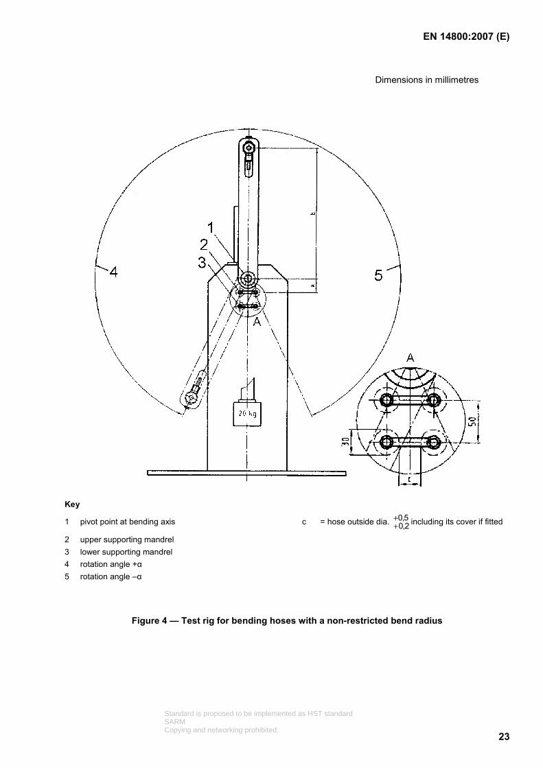
5.14.1.2 Test procedure
A CMG hose assembly of 1m nominal length, complete with its cover if fitted shall be tested using the test rig shown in Figure 4. Appropriate values of a, b and α shall be chosen from Table 3 corresponding to the nearest value of the external diameter of the test sample.
The hose shall be bent around freely rotating mandrels of 30 mm diameter.
The stationary end of the hose shall be loaded with a mass of 20 kg.
A minimum number of 3 assemblies shall be tested. Each sample shall be subjected to 50 cycles, one cycle being from the neutral position to +α, back through the neutral position to –α and ending at the neutral position. The test shall be carried out at a rate of (10 ± 1) cycles per minute.
After the test the sample shall pass the requirements of 5.3.1.
Standard is proposed to be implemented as HST standardSARMCopying and networking prohibited.
EN 14800:2007 (E)
23
Dimensions in millimetres
Key
1 pivot point at bending axis c = hose outside dia. 5,02,0
++ including its cover if fitted
2 upper supporting mandrel 3 lower supporting mandrel 4 rotation angle +α 5 rotation angle –α
Figure 4 — Test rig for bending hoses with a non-restricted bend radius
Standard is proposed to be implemented as HST standardSARMCopying and networking prohibited.
EN 14800:2007 (E)
24
Table 3 — The relationship between hose diameter and test rig geometry
Hose diameter 10 mm to 17 mm 18 mm to 25 mm 26 mm to 30 mm
Dimension a 35 mm 40 mm 45 mm
Dimension b 765 mm 760 mm 755 mm
Rotation angle α 175° 175° 175°
Hose diameter: External hose diameter at the location of bend including its cover if fitted.
Dimension a: Distance from centreline of bending mandrels to centre of pivot point.
Dimension b: Length of rotation arm measured from centre of pivot point to the sealing surface of the end fitting of the CMG hose assembly
Rotation angle α : Angle between vertical metal hose axis and end position of rotating arm measured at the pivot point.
5.14.2 Bending performance for type 2 hoses having a restricted bend radius
5.14.2.1 Requirements
The CMG hose assembly shall be capable of resisting repeated bending to a radius limited by its construction, without leakage or deterioration.
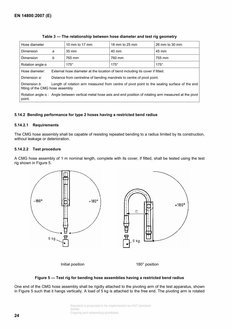
5.14.2.2 Test procedure
A CMG hose assembly of 1 m nominal length, complete with its cover, if fitted, shall be tested using the test rig shown in Figure 5.
Initial position 180° position
Figure 5 — Test rig for bending hose assemblies having a restricted bend radius
One end of the CMG hose assembly shall be rigidly attached to the pivoting arm of the test apparatus, shown in Figure 5 such that it hangs vertically. A load of 5 kg is attached to the free end. The pivoting arm is rotated
Standard is proposed to be implemented as HST standardSARMCopying and networking prohibited.

EN 14800:2007 (E)
25
in one direction through 180° and returned to the starting point, then rotated to the opposite direction through 180° and returned to the starting position, this comprising one cycle.
During the first cycle, the dimension D is measured at the two 180° positions, the test is repeated for a total of 100 cycles at a rate of 5 to 10 cycles per minute, and the two dimensions are measured again. Neither dimension shall change by more than ± 15 %. The dimension D under load shall be between a maximum of 250 mm and a minimum of 150 mm.
NOTE Any swinging of the weight may be damped without influencing the cycling operation.
After the test, the sample shall pass the requirement of 5.3.1.
5.15 Flexing resistance
5.15.1 Requirements
A CMG hose assembly shall be capable of resisting regular flexing during a reasonable working life and remain sound.
5.15.2 Test procedure
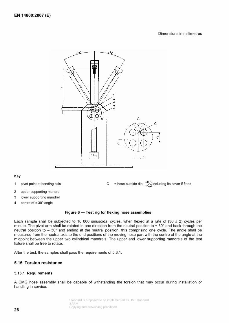
Three CMG hose assemblies of 1 m nominal length, complete with their cover if fitted shall be tested on the same basic test rig given in 5.14.1 and shown in Figure 4. The values of dimension a and b shall be as given in Table 3 of 5.14.1 but other parameters shall be as shown in Figure 6 and described below.
The stationary end of the hose is loaded with a mass of 5 kg.
Standard is proposed to be implemented as HST standardSARMCopying and networking prohibited.
EN 14800:2007 (E)
26
Dimensions in millimetres
Key
1 pivot point at bending axis C = hose outside dia. 5,02,0
++ including its cover if fitted
2 upper supporting mandrel 3 lower supporting mandrel 4 centre of ± 30° angle
Figure 6 — Test rig for flexing hose assemblies
Each sample shall be subjected to 10 000 sinusoidal cycles, when flexed at a rate of (30 ± 2) cycles per minute. The pivot arm shall be rotated in one direction from the neutral position to + 30° and back through the neutral position to – 30° and ending at the neutral position, this comprising one cycle. The angle shall be measured from the neutral axis to the end positions of the moving hose part with the centre of the angle at the midpoint between the upper two cylindrical mandrels. The upper and lower supporting mandrels of the test fixture shall be free to rotate.
After the test, the samples shall pass the requirements of 5.3.1.
5.16 Torsion resistance
5.16.1 Requirements
A CMG hose assembly shall be capable of withstanding the torsion that may occur during installation or handling in service.
Standard is proposed to be implemented as HST standardSARMCopying and networking prohibited.
EN 14800:2007 (E)
27
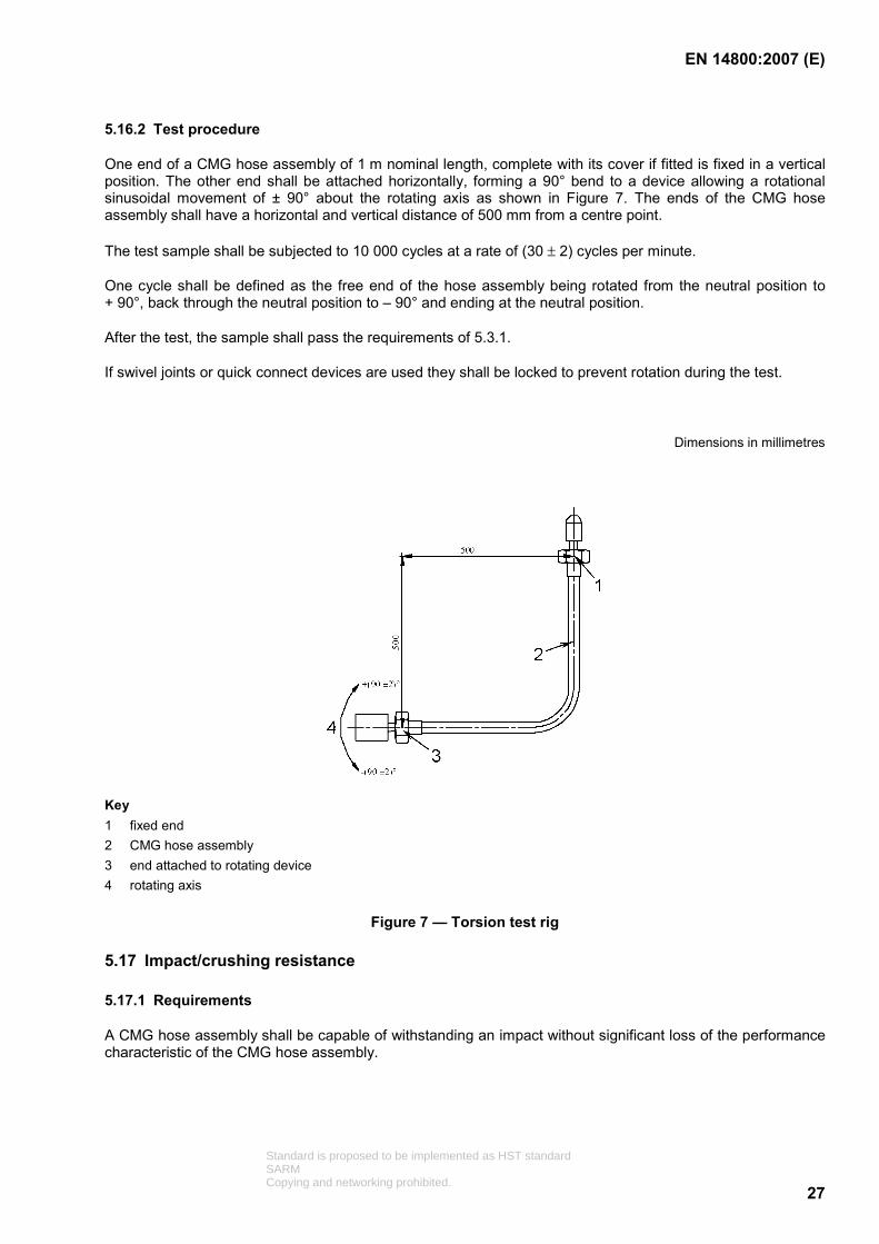
5.16.2 Test procedure
One end of a CMG hose assembly of 1 m nominal length, complete with its cover if fitted is fixed in a vertical position. The other end shall be attached horizontally, forming a 90° bend to a device allowing a rotational sinusoidal movement of ± 90° about the rotating axis as shown in Figure 7. The ends of the CMG hose assembly shall have a horizontal and vertical distance of 500 mm from a centre point.
The test sample shall be subjected to 10 000 cycles at a rate of (30 ± 2) cycles per minute.
One cycle shall be defined as the free end of the hose assembly being rotated from the neutral position to + 90°, back through the neutral position to – 90° and ending at the neutral position.
After the test, the sample shall pass the requirements of 5.3.1.
If swivel joints or quick connect devices are used they shall be locked to prevent rotation during the test.
Dimensions in millimetres
Key 1 fixed end 2 CMG hose assembly 3 end attached to rotating device 4 rotating axis
Figure 7 — Torsion test rig
5.17 Impact/crushing resistance
5.17.1 Requirements
A CMG hose assembly shall be capable of withstanding an impact without significant loss of the performance characteristic of the CMG hose assembly.
Standard is proposed to be implemented as HST standardSARMCopying and networking prohibited.

EN 14800:2007 (E)
28
5.17.2 Test procedure
The CMG hose assembly including any external cover shall be placed in a test apparatus as shown in Figure 8. The test apparatus shall be placed on a working bench.
A mass of 5 kg is dropped on the hose in free fall from a height of 600 mm.
After the test the flow rate of the CMG hose assembly shall be at least 90 % of the flow rate requirements given in 5.5.1 and the hose assembly shall fulfil the requirements of 5.3.1.
Dimension in millimetres
Key 1 guiding shell 2 mass of 5 kg 3 mobile steel plate of 70 mm length 4 supporting steel surface 5 mobile plate W external diameter of CMG hose assembly + 20 mm approximately
Figure 8 — Impact and crushing test rig
5.18 Penetration resistance
5.18.1 Requirements
When subjected to the test method described in 5.18.2 a CMG hose assembly shall remain tight when tested in accordance with 5.3.1.
5.18.2 Test method
A striker of 1kg mass and with a flat head of 12 mm diameter, the edges having a radius of 0,5 mm, shall be dropped from a height of 0,4 m onto the CMG hose close to the fitting (20 mm from the insert of the fitting or the nut), see Figure 9.
Standard is proposed to be implemented as HST standardSARMCopying and networking prohibited.

EN 14800:2007 (E)
29
Dimensions in millimetres
Key 1 striker 2 striker guide 3 flexible part of CMG hose assembly 4 detail A
Figure 9 — Penetration resistance test configuration
5.19 End fittings
5.19.1 Requirements
After testing in accordance with 5.19.2.1 and 5.19.2.2, end fittings shall be leak-tight when connected to their mating parts.
For the leak-tightness test to the connecting parts, dummy fittings may be used.
Annex A contains existing designs of end fittings that are currently in use.
5.19.2 Test procedures
5.19.2.1 Drop test
A CMG hose assembly of 1 m length shall be mounted in a test arrangement as shown in Figure 10. The end fitting shall be released and allowed to strike the steel plate a total of 25 times.
After the test the end fitting shall not show any sign of deformation or damage, which may reasonably be expected to impair its performance and when connected to a mating part it shall pass a leak-tightness test according to 5.3.1.
Standard is proposed to be implemented as HST standardSARMCopying and networking prohibited.

EN 14800:2007 (E)
30
Dimensions in millimetres
1
3
600
600±15
2
4
Key 1 suitable rigid support 2 end fitting 3 6 mm thick 300 mm square steel plate 4 floor
Figure 10 — Drop test rig
5.19.2.2 Crush test
An end fitting of a CMG hose assembly is placed between a pair of steel plates such that the plates make contact with the end fitting over the length of the largest diameter. A load of 400 N is applied gradually to the upper plate and left in place for 1 min before removal of the end fitting from the apparatus.
After the test the end fitting shall not show any sign of deformation or damage, which may reasonably be expected to impair its performance and when connected to a mating part it shall pass a leak-tightness test according to 5.3.1.
5.19.3 End fittings bodies manufactured from more than one part
5.19.3.1 Requirements
Where an end fitting is manufactured from two or more components, these components shall be connected integrally, be non-detachable and shall meet the requirements of the following test.
5.19.3.2 Torque test
A torque of 100 N ⋅ m shall be gradually applied between the components and held for 1 min. If the design has an integrated threaded part, the torsion shall be applied in the direction of loosening the thread. The components shall not come apart or be damaged. Following the test the fitting shall pass the requirements of 5.3.1.
Standard is proposed to be implemented as HST standardSARMCopying and networking prohibited.

EN 14800:2007 (E)
31
6 Evaluation of conformity
6.1 General
The conformity of a CMG hose assembly with the requirements of this standard and with the stated values shall be demonstrated by:
initial type testing,
factory production control by the manufacturer, including product assessment.
For the purpose of testing, CMG hose assemblies may be grouped into families of the same nominal diameter and similar design which shall mean that the declared performance of the designed characteristic is representative of the family. In case of dissimilar fitting designs in the same family of hoses, only fitting related tests shall be repeated.
6.2 Type testing
6.2.1 Initial type testing
6.2.1.1 General
Initial type testing shall be performed to show conformity with this European Standard on first use of this European Standard for CMG hose assemblies being put onto the market and:
at the beginning of the production of a new or modified CMG hose assembly design or change in materials of the components,
at the beginning of a new or modified method of production.
In case of type testing on CMG hose assemblies for which initial type testing in accordance with this European Standard has already been performed, type testing may be reduced:
if it has been established that performance characteristics compared with the already tested CMG hose assemblies is the same, or
in accordance with the rules for grouping into same families given in 6.1.
6.2.1.2 Characteristics
All tests in Clause 5 shall be performed as initial type testing except for the release of dangerous substances which may be declared based upon control of raw materials.
6.2.1.3 Sampling, testing and compliance criteria
Initial type testing shall be performed on samples of CMG hose assemblies representative of the manufactured types, and shall be chosen at random from either a production lot, or, in the absence of available lots, assemblies representative of the production, or, away from the manufacturers premises, products from the market.
The number of CMG hose assemblies to be tested shall be in accordance with 5.2. Tests shall be performed according to the given test sequence and compliance sequence of 5.2.
The results of all tests shall be recorded and held by the manufacturer for at least 10 years after the date of production of the particular CMG assembly.
Standard is proposed to be implemented as HST standardSARMCopying and networking prohibited.
EN 14800:2007 (E)
32
6.2.2 Subsequent type testing
Subsequent type testing shall be performed upon modification of product or production characteristics as given in 6.2.1.1.
6.3 Factory production control (FPC)
6.3.1 General
The manufacturer shall establish, document and maintain an FPC system to ensure that the products placed on the market conform to the declared performance characteristics. The FPC system shall consist of written procedures (works manual), regular inspections and tests and the use of results to control raw and other incoming materials or components, equipment, the production process and the product. Records shall remain legible, readily identifiable and retrievable.
An FPC system conforming with the requirements of EN ISO 9001 and made specific to the requirements of this European Standard is considered to satisfy above requirements.
The results of inspections or tests requiring action shall be recorded, as shall any action taken. The action to be taken when control values or criteria are not met shall be recorded and retained for the period specified in the manufacturer’s FPC procedures.
6.3.2 FPC requirements for all manufacturers
The manufacturer shall establish procedures to ensure that the production tolerances allowed for the CMG hose assemblies performance conform to the declared values, derived from initial type testing.
The characteristics minimum test frequencies shall be as given in Table 4.
Standard is proposed to be implemented as HST standardSARMCopying and networking prohibited.

EN 14800:2007 (E)
33
Table 4 — Minimum frequency of testing for product testing and evaluation as part of FPC for each product family
Property Clause, indicating
the relevant test
Minimum number of
samples / test
Minimum frequency
of test
Leak-tightness 5.3 1 Each piece produced
Structural strength 5.4 3 Every 10 000 pieces
but at least 4 × per year of continuous production
or for single small batch production 1 × per batch
Flow rate 5.5 1 Same as for 5.4 above
Electric continuity 5.6 1 1 × per year
Tension 5.7 1 1 × per year
Durability of marking 5.8 1 1 × per year
Corrosion resistance 5.10 1 1 × per year
Reaction to fire 5.11 1 1 × per year
Resistance to high temperature
5.12 1 1 × per year
Suppleness 5.13 1 1 × per year
Bending 5.14.1 or 5.14.2 3 Every 10 000 pieces
but at least 4 × per year of continuous production or for single small batch production
1 × per batch
Flexing 5.15 3 Same as for 5.14.1 and 5.14.2 above
Working temperature 5.9 2 4 × per year
Impact resistance 5.17 2 4 × per year
Penetration resistance 5.18 2 4 × per year
Torsion resistance 5.16 1 4 × per year
Structural integrity of fittings 5.19 1 1 × per year
If a single sample of the test batch fails a further sample batch consisting of a minimum of twice the original sample batch from the same manufacturing lot shall be repeated and if one of the new samples fails the production lot shall be rejected.
The manufacturer shall record the results of the tests specified above. The records shall as a minimum include the following information:
identification of the CMG hose assembly tested;
the date of sampling and testing;
the test method performed;
the test result;
Standard is proposed to be implemented as HST standardSARMCopying and networking prohibited.

EN 14800:2007 (E)
34
authorized person responsible.
6.3.3 Manufacturer-specific FPC system requirements
6.3.3.1 Personnel
The responsibility, authority and relationship between personnel who manage, perform or verify work affecting product conformity, shall be defined. This applies in particular to personnel who need to initiate actions preventing product non-conformities from occurring, actions in case of non-conformities and to identify and register product conformity problems. Personnel performing work affecting product conformity shall be competent on the basis of appropriate education, training, skills and experience for which records shall be maintained.
6.3.3.2 Equipment
All manufacturing, weighing, measuring and testing equipment necessary to achieve, or produce evidence of, conformity shall be calibrated or verified and regularly inspected according to documented procedures, frequencies and criteria. Control of monitoring and measuring devices shall be in accordance with EN ISO 9001:2000, 7.6.
All equipment used in the manufacturing process shall be regularly inspected and maintained to ensure use, wear or failure does not cause inconsistency in the manufacturing process.
Inspection and maintenance shall be carried out and recorded in accordance with the manufacturer’s written procedures and the records retained for the period defined in the manufacturer’s FPC procedures.
6.3.3.3 Raw materials and components
The specification of all incoming raw materials and components shall be documented, as shall the inspection scheme for ensuring their conformity. The verification of conformity of the raw material with the specification shall be in accordance with EN ISO 9001:2000, 7.4.3.
6.3.3.4 In-process control
The manufacturer shall plan and carry out production under controlled conditions. Production shall incorporate a final leak test as given in 5.3.1 for each individual CMG hose assembly put on the market.
Compliance with EN ISO 9001:2000, 7.5.1 and 7.5.2 shall be deemed to satisfy the requirements of this subclause.
6.3.3.5 Traceability
Individual production lots shall be identifiable and traceable with regard to their production origin. The manufacturer shall have written procedures ensuring that processes related to affixing traceability codes are inspected regularly. Compliance with EN ISO 9001:2000, 7.5.3 shall be deemed to satisfy the requirements of this subclause.
6.3.3.6 Non-confirming products
The manufacturer shall have written procedures which specify how non-conforming products shall be dealt with. Any such events shall be recorded as they occur and these records shall be kept for the period defined in the manufacturer’s written procedures. Compliance with EN ISO 9001:2000, 8.3 shall be deemed to satisfy the requirements of this subclause.
Standard is proposed to be implemented as HST standardSARMCopying and networking prohibited.

EN 14800:2007 (E)
35
6.3.3.7 Corrective action
The manufacturer shall have documented procedures that instigate action to eliminate the cause of non-conformities in order to achieve conformity and/or prevent recurrence.
6.4 Installation instruction
Each CMG hose assembly shall be accompanied by installation instructions in the language of the country of its intended destination giving all necessary information regarding its safe installation and usage together with details of the leak-tightness test that should be used at installation and during its lifetime.
The instructions shall detail:
the method and procedure of how to install the hose assembly and how to verify its correct installation;
the method of how to check for the presence of any gaskets and the control procedure to ensure that gaskets are not damaged;
the verification of leak-tightness after installation of the hose assembly and its connecting parts.
The instructions shall in addition give as a minimum the following information:
trade name of the manufacturer, the product and the product type (1 or 2);
logo of the Certification Body;
number of this European Standard, i.e. EN 14800;
type(s) of gas for which the assembly is designed;
smallest allowable bend radii which are allowed during
a) installation and
b) usage;
pressure rating of the hose assembly;
the necessity to replace gaskets every time they are damaged;
type of gasket to be used for replacement purposes
together with the following text:
“Safety metal hose assembly for use with domestic gas appliances”.
and warnings:
“Any deterioration or destruction of any part of the assembly shall result in the need to replace the complete assembly; alterations to any part of the assembly shall mean that the assembly is no longer in conformity with this European Standard”;
DO NOT
“twist or over bend”;
“Place in areas warmer than 60 °C”;
Standard is proposed to be implemented as HST standardSARMCopying and networking prohibited.

EN 14800:2007 (E)
36
“Connect two or more assemblies together in order to increase the overall length”;
“Install this assembly if any doubt exists regarding the compatibility of its fittings and those on the appliance or the gas supply”;
“Use adapters in order to achieve compatibility of fittings”;
“Install this hose assembly into a wall, floor or ceilings”;
“Install this assembly upstream of the pressure reduction valve”;
DO
“Ensure that this assembly allows an adequate flow rate for its intended use”;
“Install in accordance with existing local and National Regulations as well as best custom and practice”;
“Follow both the installation instructions of the hose assembly manufacturer and those of the appliance manufacturer, including those for the position and orientation of the connection point".
NOTE These instructions and warnings can be supplemented as required by drawings.
6.5 Packaging
The manufacturer shall provide a visible warning that installation should be performed by authorized personnel where this is required by National Regulations.
Each CMG hose assembly shall be protected against the ingress of any foreign matter into any of the parts of the hose assembly.
NOTE This requirement can be met by individual sealed packaging of the assemblies.
The manufacturer shall provide visible recommendations concerning coiling.
In order to draw the attention of the user, products with restricted bending radius shall be marked on the packaging: “Not to be used for installations requiring small bend radius”.
The packaging is also marked according to ZA.3.
Standard is proposed to be implemented as HST standardSARMCopying and networking prohibited.

EN 14800:2007 (E)
37
Annex A (informative)
Hose fitting design requirements for connection to the gas supply
pipework, to the pressure reduction device of portable gas bottles or to domestic appliance
Table A.1 — Hose fitting design requirements for connection to the gas supply pipework
Currently used in
Existing national standard
Standardized design
Spain UK Ireland
UNE 60715-2 BS 669-1:1989, Section 3
Dimensions in millimetres
Key 1 plug 2 plug ring Essential dimensions of R½ size plug connectors
Figure A.1 — Plug – DN 8 and DN 12
NOTE 1 The illustrations and dimensions given are purely schematic. For design and performance information refer to the national standards.
Standard is proposed to be implemented as HST standardSARMCopying and networking prohibited.
EN 14800:2007 (E)
38
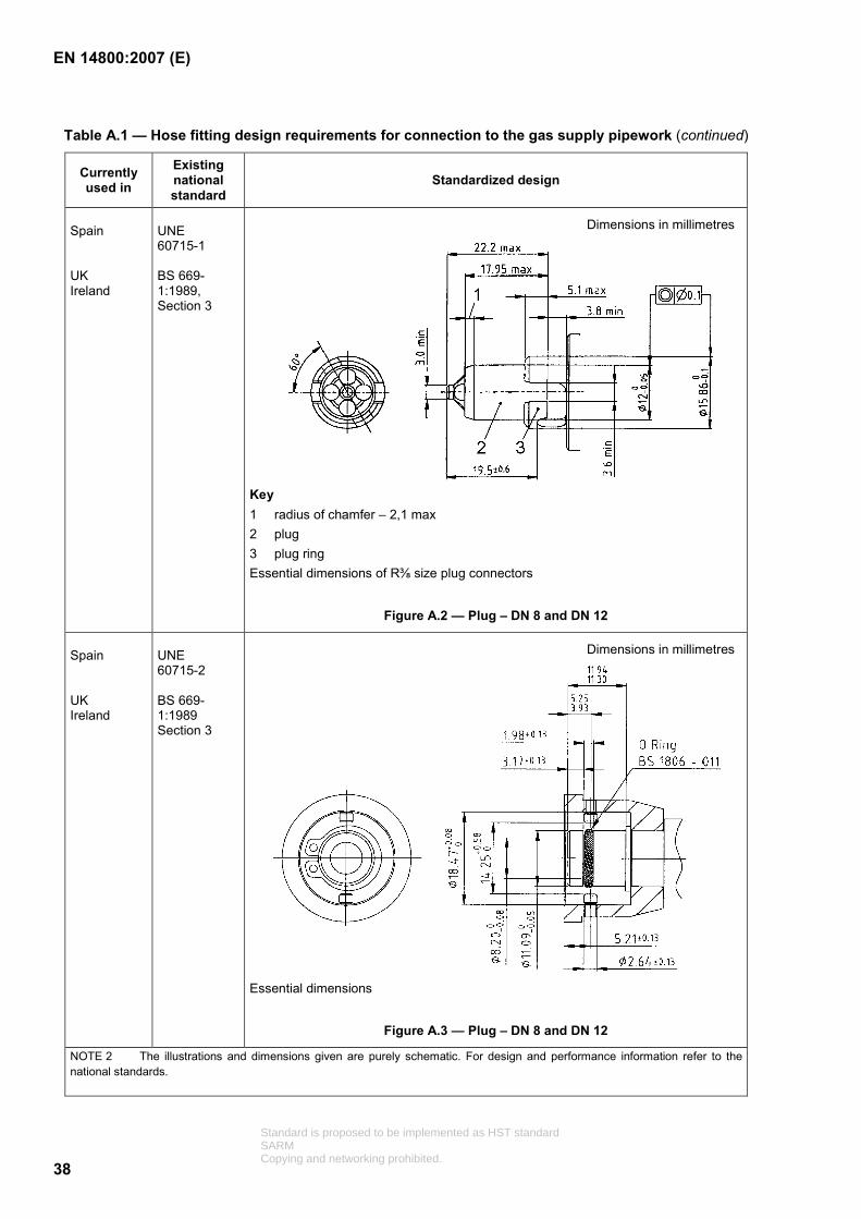
Table A.1 — Hose fitting design requirements for connection to the gas supply pipework (continued)
Currently used in
Existing national standard
Standardized design
Spain UK Ireland
UNE 60715-1 BS 669-1:1989, Section 3
Dimensions in millimetres
Key 1 radius of chamfer – 2,1 max 2 plug 3 plug ring Essential dimensions of R⅜ size plug connectors
Figure A.2 — Plug – DN 8 and DN 12
Spain UK Ireland
UNE 60715-2 BS 669-1:1989 Section 3
Dimensions in millimetres
Essential dimensions
Figure A.3 — Plug – DN 8 and DN 12
NOTE 2 The illustrations and dimensions given are purely schematic. For design and performance information refer to the national standards.
Standard is proposed to be implemented as HST standardSARMCopying and networking prohibited.

EN 14800:2007 (E)
39
Table A.1 — Hose fitting design requirements for connection to the gas supply pipework (continued)
Currently used in
Existing national
standard or regulation
Standardized design
Austria Germany Sweden Netherlands Spain Switzerland
ÖNORM M7438 DIN 3383-1 UNE 60715-2 Gastec QA69
Key 1 2 slots 180° apart
Figure A.4 — Plug – DN 12
Germany Sweden
DVGW VP 635-1
Dimensions in millimetres
Figure A.5 — Connecting plug – DN 12
NOTE 3 The illustrations and dimensions given are purely schematic. For design and performance information refer to the national standard or regulation.
Dimensions in millimetres
Standard is proposed to be implemented as HST standardSARMCopying and networking prohibited.

EN 14800:2007 (E)
40
Table A.1 — Hose fitting design requirements for connection to the gas supply pipework (continued)
Currently used in
Existing national
regulation Standardized design
Dimensions in millimetres
a) Hose assembly with nipple b) Hose assembly with nipple and 90° elbows
Germany Sweden
DVGW VP 635-1
Figure A.6 — Hose assembly – DN 12
Germany Spain Sweden Switzerland
DIN 3383-2
Figure A.7 — Nipple and swivel nut – DN 12
NOTE 4 The illustrations and dimensions given are purely schematic. For design and performance information refer to the national standard or regulation.
Standard is proposed to be implemented as HST standardSARMCopying and networking prohibited.

EN 14800:2007 (E)
41
Table A.1 — Hose fitting design requirements for connecting to the gas supply pipework (continued)
Currently used in
Existing national standard
Standardized design
Dimension in millimetres
Key DN nominal diameter F minimal internal diameter M minimal width of wrench surface d conical thread as per UNI ISO 7-1 S wrench size DN F M d S 10 10 4,0 R⅜ 17 15 12 5,0 R½ 22
NOTE 5 The requirements of DN 8 and DN 12 given in this European Standard apply to the sizes 10 and 15 given in this table.
Italy Spain
UNI 9891
Figure A.8 — Fixed male thread – DN 8 and DN 12
NOTE 6 The illustrations and dimensions given are purely schematic. For design and performance information refer to the national standards.
Standard is proposed to be implemented as HST standardSARMCopying and networking prohibited.

EN 14800:2007 (E)
42
Table A.1 — Hose fitting design requirements for connection to the gas supply pipework (continued)
Currently used in
Existing national standard
Standardized design
Dimensions in millimetres
Key 1= W width across flats 2= NL nominal length
Dimensions without tolerances shall be within ± 0,1 mm. Shapes and dimensions without specification are under manufacturer‘s initiative.
a) Gasket
Hardness ( 5480+
−) D.I.D.C.
b) Nipple
Raw material: metal withstanding corrosion
(1) Size equal or greater than the height of the swivel nut. Angles will be edge cut to avoid any damage to the gasket.
(2) D ≤ 15,7 mm.
(3) The upper face shall allow the use of a spanner as described in ISO 691:2005 and remains accessible after the swivel nut is mounted.
c) Swivel nut
Colour: other than black
Raw material: metal withstanding corrosion
The swivel nut screwed shall have at least 3 fillets engaged.
(4) Height of the hex at least equal to the depth of the threading.
(5) In case of existing groove the useable part of the threading has to be 7 mm as a minimum.
(6) When a groove is designed, the diam. of the groove shall be equal to ( )5,0
021+− mm.
France for type 1 only
NF D36-121
Swivel nut to be of any colour other than black.
Figure A.9 — Nipple and swivel nut – DN 12
NOTE 7 The illustrations and dimensions given are purely schematic. For design and performance information refer to the national standards.
Standard is proposed to be implemented as HST standardSARMCopying and networking prohibited.

EN 14800:2007 (E)
43
Table A.1 — Hose fitting design requirements for connection to the gas supply pipework (continued)
Currently used in
Existing national standard
Standardized design
Dimension in millimetres
Key 1 gasket 2 hexagonal swivel nut
DN F S D A H T Gasket dimensions
10 10 19 G⅜ 14,5 8 1,5 14,5 × 10 × 2 15 12 24 G½ 18,0 10 1,5 18,0 × 12 × 2
Italy Portugal
UNI 9891
Figure A.10 — Nipple and swivel nut – DN 8 and DN 12
NOTE 8 The requirements of DN8 and DN 12 given in this European Standard apply to the sizes 10 and 15 given in this table.
Standard is proposed to be implemented as HST standardSARMCopying and networking prohibited.
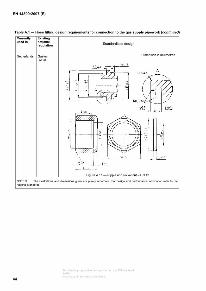
EN 14800:2007 (E)
44
Table A.1 — Hose fitting design requirements for connection to the gas supply pipework (continued) Currently used in
Existing national regulation
Standardized design
Netherlands
Gastec QA 34
Dimension in millimetres
Figure A.11 — Nipple and swivel nut – DN 12
NOTE 9 The illustrations and dimensions given are purely schematic. For design and performance information refer to the national standards.
Standard is proposed to be implemented as HST standardSARMCopying and networking prohibited.

EN 14800:2007 (E)
45
Table A.1 — Hose fitting design requirements for connection to the gas supply pipework (concluded)
Currently used in
Existing national standard
Standardized design
Belgium
NBN E 03.101 for thread
Dimension in millimetres
Fixed male thread
Nipple with metal to metal tight contact on the female thread
Figure A.12 — Fixed male thread and fixed female thread – DN 12
NOTE 10 The illustrations and dimensions given are purely schematic. For design and performance information refer to the national standards.
Standard is proposed to be implemented as HST standardSARMCopying and networking prohibited.

EN 14800:2007 (E)
46
Table A.2 — Hose fitting requirements for connection to the pressure reduction device of portable gas cylinders
Currently used in
Existing national standard
Standardized design
France
for type 1 only
NF D36-125
Key 1 W Width across flats 2 NL Nominal length
Figure A.13 — Nipple and swivel nut DN 12
Dimensions in millimetres
Detail of fitting to retain gasket
Dimensions without tolerances shall be within ± 0,1 mm. Shapes and dimensions without specification are under manufacturer‘s initiative.
a) Gasket
Colour: other than black and possibility of orange identification
Hardness ( 5480+
−) D.I.D.C.
b) Nipple
Raw material: metal withstanding corrosion
(1) Size equal or greater than the height of the swivel nut. Angles will be edge cut to avoid any damage to the gasket. The upper faces (if any) will fulfil the sketch.
(2) D ≤ 15,1 mm.
c) Swivel nut
Colour: black
Raw material: metal withstanding corrosion
(4) Height of the hex 50 % of the height of the swivel nut.
NOTE 1 The illustrations and dimensions given are purely schematic. For design and performance information refer to the national standards.
Standard is proposed to be implemented as HST standardSARMCopying and networking prohibited.

EN 14800:2007 (E)
47
Table A.2 — Hose fitting design requirements for connection to the pressure reduction device of portable gas cylinders (continued)
Currently used in
Existing national standard
Standardized design
Spain UK Ireland
UNE 60-715-1 60-715-2 BS 669-1:1989, Section 3
Dimensions in millimetres
Figure A.14 — Fixed male thread – DN 8 and DN 12
Dimensions in millimetres
Key 1 gasket 2 hexagonal swivel nut
DN F S D A H T Gasket dimensions
10 10 19 G⅜ 14,5 8 1,5 14,5 × 10 × 2 15 12 24 G½ 18,0 10 1,5 18,0 × 12 × 2
Figure A.15 — Nipple and swivel nut – DN 10 and DN 15
Italy
UNI 9891
NOTE 2 The requirements of DN 8 and DN 12 given in this European Standard apply to the sizes 10 and 15 given in this table.
NOTE 3 The illustrations and dimensions given are purely schematic. For design and performance information refer to the national standards.
Standard is proposed to be implemented as HST standardSARMCopying and networking prohibited.

EN 14800:2007 (E)
48
Table A.2 — Hose fitting design requirements for connection to the pressure reduction device of portable gas cylinders (concluded)
Currently used in
Existing national standard
Standardized design
Dimensions in millimetres
DN G d (max.)
b (min.)
p (min.)
r (min.)
m (min.)
l (min.)
F (min.)
8 ¼'' 8 11,0 1 1 2 2 7 12 ½'' 14 17,3 1 1 2 2 7
Spain
UNE 60715-2
Figure A.16 — Nipple and swivel nut – DN 8 and DN 12
NOTE 4 The lip is optional. Other designs of the flat faced nipple support are also accepted provided they fulfil the function of holding back the seal.
If this is achieved without a collar then the minimum height (M+P) shall be 3 mm.
NOTE 5 The illustrations and dimensions given are purely schematic. For design and performance information refer to the national standards.
Standard is proposed to be implemented as HST standardSARMCopying and networking prohibited.

EN 14800:2007 (E)
49
Table A.3 — Hose fitting design requirements for connection to the domestic appliance
Currently used in
Existing national standard
Standardized design
Spain Portugal UK Ireland
UNE 60715-1 60715-2 BS 669-1
Dimensions in millimetres
Figure A.17 — Fixed male thread – DN 8 and DN 12
Austria Germany Sweden Netherlands Spain
ÖNORM M7438 DIN 3383
Dimension in millimetres
Figure A.18 — Fixed female thread – DN 12
Key SW 24 = 24 mm width across flats
NOTE 1 The illustrations and dimensions given are purely schematic. For design and performance information refer to the national standards.
Standard is proposed to be implemented as HST standardSARMCopying and networking prohibited.

EN 14800:2007 (E)
50
Table A.3 — Hose fitting design requirements for connection to the domestic appliance (continued)
Currently used in
Existing national
regulation Standardized design
Germany Sweden
DVGW VP 635-1
Dimensions in millimetres
Key 1 connection part 2 swivel nut 3 nipple
Figure A.19 — Assembled plug connection
Key 1 rounded SW 27 = 27 mm width across flats General tolerances EN 22768-1 – m
Figure A.20 — Connecting piece
NOTE 2 The illustrations and dimensions given are purely schematic. For design and performance information refer to the national standard or regulation.
Standard is proposed to be implemented as HST standardSARMCopying and networking prohibited.

EN 14800:2007 (E)
51
Table A.3 — Hose fitting design requirements for connection to the domestic appliance (continued)
Currently used in
Existing national
regulation Standardized design
Germany Sweden
DVGW VP 635-1
Dimensions in millimetres
Key 1 safety advice 2 O-Ring 15 × 2 3 surface RGE 08 DIN 82 General tolerances EN 22768-1 – m
Figure A.21 — Nipple with swivel nut
Safety advice (sticker glued or permanently inscribed) To assemble: enter the plug into the gas socket, then tighten the back nut.To dismantle: undo the back nut, then pull out the plug.
NOTE 3 The illustrations and dimensions given are purely schematic. For design and performance information refer to the national standard or regulation.
Standard is proposed to be implemented as HST standardSARMCopying and networking prohibited.
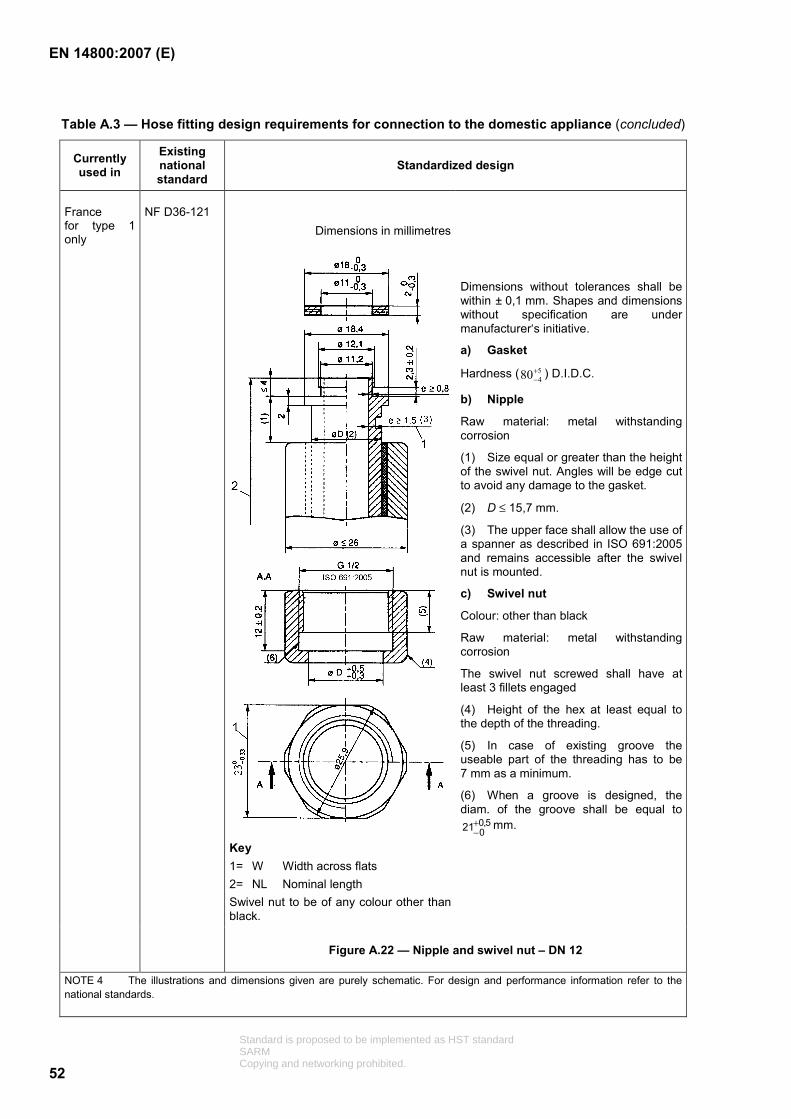
EN 14800:2007 (E)
52
Table A.3 — Hose fitting design requirements for connection to the domestic appliance (concluded)
Currently used in
Existing national standard
Standardized design
Dimensions in millimetres
Key 1= W Width across flats 2= NL Nominal length Swivel nut to be of any colour other than black.
Dimensions without tolerances shall be within ± 0,1 mm. Shapes and dimensions without specification are under manufacturer‘s initiative.
a) Gasket
Hardness ( 5480+
− ) D.I.D.C.
b) Nipple
Raw material: metal withstanding corrosion
(1) Size equal or greater than the height of the swivel nut. Angles will be edge cut to avoid any damage to the gasket.
(2) D ≤ 15,7 mm.
(3) The upper face shall allow the use of a spanner as described in ISO 691:2005 and remains accessible after the swivel nut is mounted.
c) Swivel nut
Colour: other than black
Raw material: metal withstanding corrosion
The swivel nut screwed shall have at least 3 fillets engaged
(4) Height of the hex at least equal to the depth of the threading.
(5) In case of existing groove the useable part of the threading has to be 7 mm as a minimum.
(6) When a groove is designed, the diam. of the groove shall be equal to
5,0021+
−mm.
France for type 1 only
NF D36-121
Figure A.22 — Nipple and swivel nut – DN 12
NOTE 4 The illustrations and dimensions given are purely schematic. For design and performance information refer to the national standards.
Standard is proposed to be implemented as HST standardSARMCopying and networking prohibited.

EN 14800:2007 (E)
53
Annex B (normative)
Thermal attack by a single burning item
B.1 General
Side view
Key 1 hose assembly sample OAL 1250 mm a = 100 mm b = 300 mm c = 50 mm e = 250 mm
Figure B.1 — Testing rig for single burning item test
Standard is proposed to be implemented as HST standardSARMCopying and networking prohibited.
EN 14800:2007 (E)
54
B.2 Scope
This annex gives the mounting instructions for reaction to fire test of CMG hoses assemblies exposed to the thermal attack by a single burning item.
The test procedure is given in EN 13823.
B.3 Standardized mounting and fixing
The sample shall be fitted in a U loop position on the large wing of the test bench. It shall be hung at both extremities by the mean of metallic squares. The distance from the longitudinal axis of the sample from the surface of the backing board shall be 50 mm.
The test shall be performed on an item equipped with its end fittings.
The outlet end fitting (appliance side) shall be placed on the side of the loop opposite from the corner.
Standard is proposed to be implemented as HST standardSARMCopying and networking prohibited.
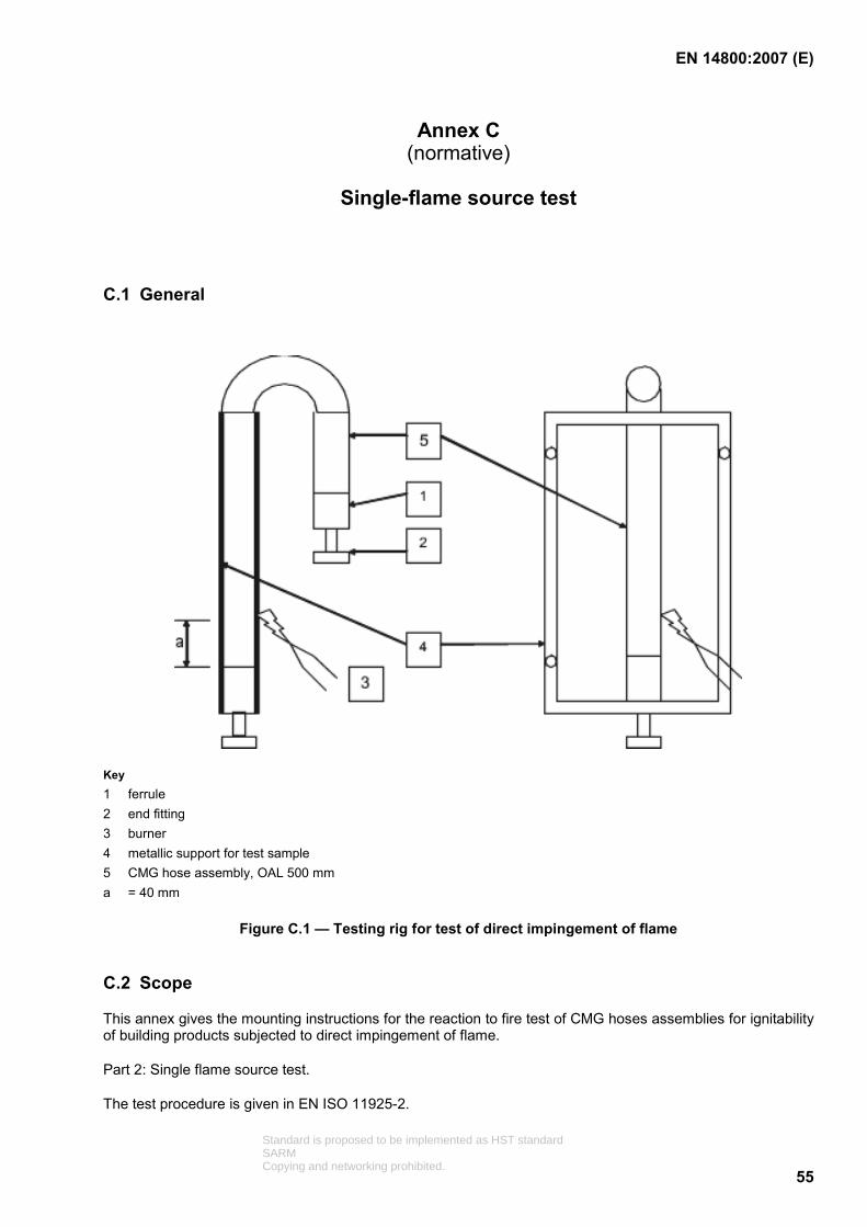
EN 14800:2007 (E)
55
Annex C (normative)
Single-flame source test
C.1 General
Key 1 ferrule 2 end fitting 3 burner 4 metallic support for test sample 5 CMG hose assembly, OAL 500 mm a = 40 mm
Figure C.1 — Testing rig for test of direct impingement of flame
C.2 Scope
This annex gives the mounting instructions for the reaction to fire test of CMG hoses assemblies for ignitability of building products subjected to direct impingement of flame.
Part 2: Single flame source test.
The test procedure is given in EN ISO 11925-2.
Standard is proposed to be implemented as HST standardSARMCopying and networking prohibited.

EN 14800:2007 (E)
56
C.3 Standardized mounting and fixing
The test shall be performed on the inlet of the CMG hose assembly (gas supply extremity).
The metallic support for the test sample shall be sized with the standard dimensions (110 mm × 295 mm).
C.4 Test definition
The test shall be performed using the surface exposition procedure. The flame attack shall be located 40 mm above the connection point of the flexible part of the CMG hose assembly and the rigid part of its end fitting.
C.5 Test duration
The flame shall be maintained during 15 s or 30 s depending on the Class to be determined.
Standard is proposed to be implemented as HST standardSARMCopying and networking prohibited.
EN 14800:2007 (E)
57
Annex ZA (informative)
Clauses of this EN addressing the provisions of EU Construction Products Directive
ZA.1 Scope and relevant characteristics
This European Standard has been prepared under a mandate M/131 "Pipes Tanks and ancillaries not in contact with water intended for human consumption" given to CEN by the European Commission and the European Free Trade Association.
The clauses of this European Standard shown in this annex meet the requirements of the mandate given under the EU Construction Products Directive (89/106/EEC).
Compliance with these clauses confers a presumption of fitness of the CMG hose assembly covered by this Annex for its intended uses indicated herein; reference shall be made to the information accompanying the CE marking.
WARNING — Other requirements and other EU Directives, not affecting the fitness of intended uses, can be applicable to the construction products falling within the scope of this European Standard.
NOTE 1 In addition to any specific clauses relating to dangerous substances contained in this standard, there may be other requirements applicable to the products falling within its scope (e.g. transposed European legislation and national laws, regulations and administrative provisions). In order to meet the provision of the EU Construction Products Directive, these requirements need also to be complied with, when and where they apply.
NOTE 2 An informative database of European and national provisions on dangerous substances is available at the Construction web site on EUROPA (accessed through http://europa.eu.int/comm/enterprise/construction/internal/dangsub/dangmain.htm ).
This annex establishes the conditions for the CE marking of the CMG hose assemblies intended for the uses indicated in Table ZA.1 and shows the relevant clauses applicable:
This annex has the same scope as Clause 1 of this standard and is defined by Table ZA.1.
Standard is proposed to be implemented as HST standardSARMCopying and networking prohibited.

EN 14800:2007 (E)
58
Table ZA.1 — Relevant clauses
Construction Product: Corrugated safety metal hose assemblies
Intended use: Connection of domestic gas appliances
Requirements/characteristic from the Mandate
Requirement Clause(s) in this or other EN(s)
Mandated level(s) and/or classe(s) Notes
Reaction to fire 5.11 See EN 13501-1 Euroclass pass/fail Crushing strength 5.17
5.19.2
- Threshold level above 29,4 Joule 400 N
Internal pressure strength 5.4 - Threshold level above 6 bar
Longitudinal bending strength 5.14.1 5.14.2 5.15 5.16
- Threshold level above 50 cycles 100 cycles 10 000 cycles 10 000 cycles
Maximum load for admissible deformation
5.7 5.13
- Threshold level above 1 000 N pass
Dimensional tolerances 5.19.1 - comply Impact resistance 5.19.2 - Threshold level above
25 times
Penetration resistance 5.18.2 - Threshold level above
3,9 Joules Electrostatic behaviour 4.8
5.6
- comply
Threshold level less than 1 Ω/m.
Tightness 5.3 - Threshold level below 10 cm3/h
Effectiveness 5.5 - ...m3/h flow rate Mechanical strength 5.7
5.19.3 - Threshold level above
6 bar 100 Nm
Release of dangerous substances
4.12 - substance “x” less than “y” ppm (or NPD)
Permeability 5.3.1 Threshold level below 10 cm3/h
Tightness (in case of fire) 5.12 - Threshold level 650 °C for 30 min
Durability 5.10 4.3/ 4.4/ 4.5/ 5.8 / 5.9 / 5.12 / 5.14 / 5.15 / 5.16 / 5.19.3
- Threshold level no visible sign of corrosion pass
Standard is proposed to be implemented as HST standardSARMCopying and networking prohibited.

EN 14800:2007 (E)
59
The requirement on a certain characteristic is not applicable in those Member States (MSs) where there are no regulatory requirements on that characteristic for the intended use of the product. In this case, manufacturers placing their products on the market of these MSs are not obliged to determine nor declare the performance of their products with regard to this characteristic and the option “No performance determined” (NPD) in the information accompanying the CE marking (see ZA.3) may be used. The NPD option may not be used, however, where the characteristic is subject to a threshold level.
ZA.2 Procedure for attestation of conformity of corrugated safety metal hose assemblies
ZA.2.1 Systems of attestation of conformity
The system of attestation of conformity of CMG hose assemblies indicated in Table ZA.1, in accordance with the Decision of the Commission 99/472/EC (amended by 2001/596/EC) as given in Annex III of the mandate for "Pipes, tanks and ancillaries not in contact with water intended for human consumption, mandate M/131", is shown in Tables ZA.2a and ZA.2b for the indicated intended use and relevant level or class:
Table ZA.2a — System(s) of attestation of conformity
Product(s)
Intended use(s)
Level(s)
or class(es)
Attestation
of conformity
system(s)
- Pipes
In installations not subjected to reaction to fire regulations,
used for the transport/distribution/storage of gas/fuel
intended for the supply of building heating/cooling systems, from the
external storage reservoir or the last pressure reduction unit of the network to the inlet of the boiler/heater/cooler
system(s) of the building(s).
___
3
System 3: See Directive 89/106/EEC (CPD) Annex III.2 (ii), Second possibility
Standard is proposed to be implemented as HST standardSARMCopying and networking prohibited.

EN 14800:2007 (E)
60
Table ZA.2b — System(s) of attestation of conformity
Product Intended use Level(s) or class(es)
Attestation of conformity system(s)
- Pipes in installations in areas subject to reaction to fire regulations,
used for the transport/distribution/storage of gas/fuel
intended for the supply of building heating/cooling systems, from the
external storage reservoir or the last pressure reduction unit of the network to the inlet of the boiler/heater/cooler
system(s) of the building(s),
any 1
System 1: See Directive 89/106/EEC (CPD) Annex III.2.(i), without audit testing of samples.
The attestation of conformity of the CMG hose assemblies in Table ZA.1 shall be based on the evaluation of conformity procedures indicated in Tables ZA.3a and ZA.3b resulting from application of the clauses of this or other European Standard indicated therein.
Table ZA.3a — Assignment of evaluation of conformity tasks for CMG hose assemblies under system 1
Tasks Content of the task Evaluation of
conformity clauses to apply
Factory production control (FPC)
Parameters related to all relevant characteristics of Table ZA.1 6.3
Further testing of samples taken at factory All relevant characteristics of Table ZA.1 6.3.2
Tasks under the responsibility of the manufacturer
Initial type testing by a notified test lab All characteristics of Table ZA.1 6.2
Initial type testing Reaction to fire 6.2
Initial inspection of factory and of FPC Parameters related to reaction to fire 6.3 Tasks under the
responsibility of the product certification body Continuous surveillance,
assessment and approval of FPC
Parameters related to reaction to fire 6.3
Standard is proposed to be implemented as HST standardSARMCopying and networking prohibited.

EN 14800:2007 (E)
61
Table ZA.3b – Assignment of evaluation of conformity tasks for CMG hose assemblies under system 3
Tasks Content of the task Evaluation of
conformity clauses to apply
Factory production control (FPC)
Parameters related to all characteristics of Table ZA.1 6.3
Further testing of samples taken at factory All characteristics of Table ZA.1 6.3.2
Tasks under the responsibility of the manufacturer
Initial type testing by a notified test lab All characteristics of Table ZA.1 6.2
ZA.2.2 EC Certificate and Declaration of conformity
(In case of System 1) When compliance with the conditions of this annex is achieved, the certification body shall draw up a certificate of conformity (EC Certificate of conformity), which entitles the manufacturer to affix the CE marking. The certificate shall include:
name, address and identification number of the certification body;
name and address of the manufacturer, or his authorized representative established in the EEA, and place of production;
description of the product (type, identification, use, ...);
provisions to which the product conforms (i.e. Annex ZA of EN 14800:2007);
particular conditions applicable to the use of the product (e.g. provisions for use under certain conditions);
the number of the certificate;
conditions and period of validity of the certificate, where applicable;
name of, and position held by, the person empowered to sign the certificate.
In addition, the manufacturer shall draw up a declaration of conformity (EC Declaration of conformity) including the following:
name and address of the manufacturer, or his authorized representative established in the EEA;
name and address of the certification body;
description of the product (type, identification, use, ...), and a copy of the information accompanying the CE marking;
provisions to which the product conforms (i.e. Annex ZA of EN 14800:2007);
particular conditions applicable to the use of the product (e.g. provisions for use under certain conditions and national regulation of installation if any);
number of the accompanying EC Certificate of conformity;
name of, and position held by, the person empowered to sign the declaration on behalf of the manufacturer or his authorized representative.
Standard is proposed to be implemented as HST standardSARMCopying and networking prohibited.

EN 14800:2007 (E)
62
(In case of System 3) When compliance with the conditions of this annex is achieved, the manufacturer or his agent established in the EEA shall draw up and retain a declaration of conformity (EC Declaration of conformity), which entitles the manufacturer to affix the CE marking.
This declaration shall include:
name and address of the manufacturer, or his authorized representative established in the EEA, and place of production;
description of the product (type, identification, use,...), and a copy of the information accompanying the CE marking;
provisions to which the product conforms (i.e. Annex ZA of this EN);
particular conditions applicable to the use of the product, (e.g. provisions for use under certain conditions and national regulation of installation if any);
name and address of the notified laboratory(ies);
name of, and position held by, the person empowered to sign the declaration on behalf of the manufacturer or his authorized representative.
ZA.3 CE Marking and labelling
Information under a) shall be engraved, impressed or embossed on a metallic part of the CMG hose assembly, information under b) shall be permanently fixed to or marked on the CMG hose assembly; information under c) if not already fixed or marked on the CMG hose assembly shall be given on accompanying commercial documents. In addition, all the information to accompany CE marking shall be shown together in one place, which may be the most convenient i.e. the commercial documentation.
a) last two digits of the year of manufacture:
identifying mark of the producer;
lot code of production.
b) identification number of the certification body:
gas type(s);
direction of the gas flow if applicable;
reference to this European Standard, i.e. EN 14800.
Additional indications are permitted, as long they do not interfere with the above markings.
c) name or identifying mark and registered address of the producer:
number of the EC Certificate;
description of the product: generic name, type, material, dimensions and intended use;
“No performance determined” for characteristics where this is relevant;
standard designation which shows all of the relevant characteristics;
Standard is proposed to be implemented as HST standardSARMCopying and networking prohibited.

EN 14800:2007 (E)
63
whether suitable or not for use in areas subjected to reaction to fire regulations.
“The “No performance determined” (NPD) option may not be used where the characteristic is subject to a threshold level. Otherwise, the NPD option may be used when and where the characteristic, for a given intended use, is not subject to regulatory requirements in the Member State of destination.
Figure ZA.1 gives an example of the information to be given on the product, label, packaging and/or commercial documents.
Standard is proposed to be implemented as HST standardSARMCopying and networking prohibited.

EN 14800:2007 (E)
64
01234
CE conformity marking, consisting of the “CE”-symbol given in Directive
93/68/EEC.
Identification number of the certification body (if relevant)
AnyCo Ltd, PO Box 21, B-1050
07
01234-CPD-00234
Name or identifying mark and registered address of the producer
Last two digits of the year in which the marking was affixed
Certificate number (if relevant)
EN 14800:2007
Corrugated metal hose assembly for natural gas, type 2 DN 12, length 1,5 m
Suitable for use in areas subjected to reaction to fire regulation
Reaction to fire : Class B-s2, d1
Dangerous substances : Substance “x” = less than “y” ppm (or NPD)
Other characteristics indicated
Crushing strength : pass
Internal pressure strength : 6 bar
Longitudinal bending strength : pass
Maximum load for admissible
Deformation : 1 000 N
Dimensional tolerances : comply
Impact resistance : pass
Penetration resistance : pass
Electrostatic behaviour : 0,8 Ω/m
Tightness :below 10 cm 3/h
Effectiveness : 1,8 m3/ h flow rate
Mechanical strength : 6 bar
Permeability : below 10 cm3/h
Tightness (in case of fire) :650 °C for 30 min
Durability : pass
No. of European Standard
Description of product
and
information on regulated characteristics
Figure ZA.1 — Example CE Marking information
Standard is proposed to be implemented as HST standardSARMCopying and networking prohibited.

EN 14800:2007 (E)
65
In addition to any specific information relating to dangerous substances shown above, the product should also be accompanied, when and where required and in the appropriate form, by documentation listing any other legislation on dangerous substances for which compliance is claimed, together with any information required by that legislation.
NOTE European legislation without national derogations need not be mentioned.
Standard is proposed to be implemented as HST standardSARMCopying and networking prohibited.

EN 14800:2007 (E)
66
Bibliography
[1] ISO 7-1, Pipe threads where pressure-tight joints are made on the threads — Part 1: Dimensions, tolerances and designation
[2] BS 669-1:1989, Flexible hoses, end fittings and sockets for gas burning appliances — Specification for strip-wound metallic flexible hoses, covers, end fittings and sockets for domestic appliances burning 1st and 2nd family gases
[3] DIN 3383-1, Hose assemblies and connection valves for gas, safety hose assemblies, safety valve with quick connecting device
[4] DIN 3383-2, Hose assemblies and connection valve for gas — Part 2: Hose assemblies for fixed connection
[5] GASTEC QA Approval Requirement 69, Metal gas taps for installations inside buildings, dated 01-01-1989
[6] GASTEC QA Approval Requirements 34, Flexible rubber hoses for connecting gas appliances, dated 01-01-1989
[7] NF D36-121, Household economy — Corrugated metallic flexible piping for the external connection of domestic appliances using gaseous fuels distributed by networks
[8] NF D36-125, Household economy — Corrugated metallic flexible piping for the external connection of domestic appliances using butane and propane from cylinders
[9] ÖNorm M7438, Safety hose assemblies for gas with quick connecting device and safety connection valves – Model M for installation in hot zones
[10] UNE 60715-1, Flexible hoses for connexion of installations to burning appliances assemblies of flexible connection with security socket and thread. Part 1: Spirally-metallic
[11] UNE 60715-2, Flexible hoses for connection of installations to burning appliances. Assemblies of flexible connection with security socket and thread. Part 2: Continuous helicoidal corrugated stainless steel flexible connection assemblies
[12] UNI 9891, Corrugated flexible safety metallic hose assemblies for the connection of gas appliances for domestic and similar uses
[13] DVGW VP 635-1, Safety gas connection valves for metallic and/or non-metallic gas pipes for the connection of flexible metallic or non metallic hose assemblies
[14] NBN E 03.101:1986, Pipe threads for tubes and fittings where pressure-tight joints are made on the threads
[15] DIN 82:1973, Knurls
[16] EN 22768-1:1993, General tolerances – Part 1: Tolerances for linear and angular dimensions without individual tolerance indications (ISO 2768-1:1989)
[17] BS 1806:1989, Specification for dimensions of toroidal sealing rings (‘O’ rings) and their housings (inch series)
ISO 691:2005, Assembly tools for screws and nuts – Wrench and socket openings – Tolerances for general use
Standard is proposed to be implemented as HST standardSARMCopying and networking prohibited.