Embed Size (px)
Citation preview

EML4552 - Spring 2009
Senior Design
Group 12
Bevel Gear Testbed
Final Analysis
Darrel Anderson Brad Childers
Andrew Dalesandro David Jones
Table of Contents
Abstract . . . . . . . . . . . . . . . . . . . . . . . . . . . . . . . . . . . . . . . . . . . . . . . . . . . . . . . . . . . Page 1
The Harris Corporation. . . . . . . . . . . . . . . . . . . . . . . . . . . . . . . . . . . . . . . . . . . . . . . Page 2
Bevel Gears . . . . . . . . . . . . . . . . . . . . . . . . . . . . . . . . . . . . . . .. . . . . . . . . . . . . Page 2
Bevel Gear Design Calculations . . . . . . . . . . . . . . . . . . . . . . . . . . . . . . . . . . . . . . . Page 3
Senior Design Project. . . . . . . . . . . . . . . . . . . . . . . . . . . . . . . . . . . . . . . . . . . . . . . . . Page 3
Concept Generation. . . . . . . . . . . . . . . . . . . . . . . . . . . . . . . . . . . . . . . . . . . . . . . . Page 4
Current Design . . . . . . . . . . . . . . . . . . . . . . . . . . . . . . . . . . . . . . . . . . . Page 13
Cost Analysis. . . . . . . . . . . . . . . . . . . . . . . . . . . . . . . . . . . . . . . . . . . . . . . . Page 17
Testing and Analysis . . . . . . . . . . . . . . . . . . . . . . . . . . . . . . . . . . . . . . . . . . . . . . . . Page 18
Propositions for Improvement . . . . . . . . . . . . . . . . . . . . . . . . . . . . . . . . . . . . . . . . . Page 18
Possible Future Plans. . . . . . . . . . . . . . . . . . . . . . . . . . . . . . . . . . . . . . . . . . . . . . . . Page 21
Conclusion. . . . . . . . . . . . . . . . . . . . . . . . . . . . . . . . . . . . . . . . . . . . . . . . . Page 24
Acknowledgements. . . . . . . . . . . . . . . . . . . . . . . . . . . . . . . . . . . . . . . . . . . . . . . . . Page 26
References. . . . . . . . . . . . . . . . . . . . . . . . . . . . . . . . . . . . . . . . . . . . . . . . . . . . . . . . Page 27
Appendix I. . . . . . . . . . . . . . . . . . . . . . . . . . . . . . . . . . . . . . . . . . . . . . . . . . . . . . . . Page 27
Appendix II . . . . . . . . . . . . . . . . . . . . . . . . . . . . . . . . . . . . . . . . . . . . . . . . . . . . . . . Page 32
Appendix III . . . . . . . . . . . . . . . . . . . . . . . . . . . . . . . . . . . . . . . . . . . . . . . . . . . . . . Page 43
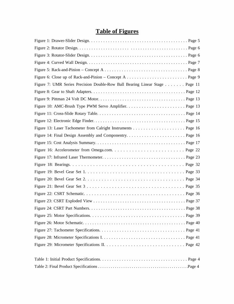
Table of Figures Figure 1: Drawer-Slider Design. . . . . . . . . . . . . . . . . . . . . . . . . . . . . . . . . . . . . . . . . Page 5
Figure 2: Rotator Design. . . . . . . . . . . . . . . . . . . . . . . . . . . . . . . . . . . . . . . . . . . . . . Page 6
Figure 3: Rotator-Slider Design. . . . . . . . . . . . . . . . . . . . . . . . . . . . . . . . . . . . . . . . . Page 6
Figure 4: Curved Wall Design. . . . . . . . . . . . . . . . . . . . . . . . . . . . . . . . . . . . . . . . . . Page 7
Figure 5: Rack-and-Pinion – Concept A . . . . . . . . . . . . . . . . . . . . . . . . . . . . . . . . . . Page 8
Figure 6: Close up of Rack-and-Pinion – Concept A . . . . . . . . . . . . . . . . . . . . . . . . Page 9
Figure 7: UMR Series Precision Double-Row Ball Bearing Linear Stage . . . . . . . Page 11
Figure 8: Gear to Shaft Adapters. . . . . . . . . . . . . . . . . . . . . . . . . . . . . . . . . . . . . . . Page 12
Figure 9: Pittman 24 Volt DC Motor. . . . . . . . . . . . . . . . . . . . . . . . . . . . . . . . . . . . Page 13
Figure 10: AMC-Brush Type PWM Servo Amplifier. . . . . . . . . . . . . . . . . . . . . . . Page 13
Figure 11: Cross-Slide Rotary Table. . . . . . . . . . . . . . . . . . . . . . . . . . . . . . . . . . . . Page 14
Figure 12: Electronic Edge Finder. . . . . . . . . . . . . . . . . . . . . . . . . . . . . . . . . . . . . . Page 15
Figure 13: Laser Tachometer from Calright Instruments . . . . . . . . . . . . . . . . . . . . Page 16
Figure 14: Final Design Assembly and Componentry. . . . . . . . . . . . . . . . . . . . . . . Page 16
Figure 15: Cost Analysis Summary. . . . . . . . . . . . . . . . . . . . . . . . . . . . . . . . . . . . . Page 17
Figure 16: Accelerometer from Omega.com. . . . . . . . . . . . . . . . . . . . . . . . . Page 22
Figure 17: Infrared Laser Thermometer. . . . . . . . . . . . . . . . . . . . . . . . . . . . . . . . . . Page 23
Figure 18: Bearings. . . . . . . . . . . . . . . . . . . . . . . . . . . . . . . . . . . . . . . Page 32
Figure 19: Bevel Gear Set 1. . . . . . . . . . . . . . . . . . . . . . . . . . . . . . . . . . . . Page 33
Figure 20: Bevel Gear Set 2. . . . . . . . . . . . . . . . . . . . . . . . . . . . . . . . . . . . Page 34
Figure 21: Bevel Gear Set 3 . . . . . . . . . . . . . . . . . . . . . . . . . . . . . . . . . . . Page 35
Figure 22: CSRT Schematic. . . . . . . . . . . . . . . . . . . . . . . . . . . . . . . . . . . . . . Page 36
Figure 23: CSRT Exploded View . . . . . . . . . . . . . . . . . . . . . . . . . . . . . . . . . . . . . . Page 37
Figure 24: CSRT Part Numbers. . . . . . . . . . . . . . . . . . . . . . . . . . . . . . . . . . . . . . . . Page 38
Figure 25: Motor Specifications. . . . . . . . . . . . . . . . . . . . . . . . . . . . . . . . . . . . . Page 39
Figure 26: Motor Schematic. . . . . . . . . . . . . . . . . . . . . . . . . . . . . . . . . . . . . . . . . . . Page 40
Figure 27: Tachometer Specifications. . . . . . . . . . . . . . . . . . . . . . . . . . . . . . . . . . Page 41
Figure 28: Micrometer Specifications I. . . . . . . . . . . . . . . . . . . . . . . . . . . . . . . . . . Page 41
Figure 29: Micrometer Specifications II. . . . . . . . . . . . . . . . . . . . . . . . . . . . . . Page 42
Table 1: Initial Product Specifications. . . . . . . . . . . . . . . . . . . . . . . . . . . . . . . . . . . . Page 4
Table 2: Final Product Specifications . . . . . . . . . . . . . . . . . . . . . . . . . . . . . . . . . . . . . . . . . . .Page 4
Abstract
Harris Corporation has requested the design and development of a fully adjustable
bevel gear testbed capable of testing the life-cycle of a wide range of bevel gear sizes,
styles and materials while meeting several alignment and loading characteristics. The
foundation for this project is the result of a previous industrial application at Harris Corp.
where the bevel gears involved failed well before the expected life cycle. The possible
problems of this failure include but are not limited to misalignment of the shafts, anodic
coating failure on the gears, and overloading of the gears. While these complications
from previous experience are a concern, Harris Corp. has also asked that the speed of the
input gear be controlled up to 100 rpm, the resistive load on the output gear be controlled
up to 50 inch-pounds, the mounting distance of the gears be controlled within ± 0.001
inch, the gears be able to rotate up to at least ± ½ degree both clockwise and counter-
clockwise accurate to ± 1/20 of a degree, and that the testbed be capable of testing gears
from 1/3 inch to 5 inches in diameter. In addition to the product specifications, the entire
system must not exceed $1500.00.
The testbed fabrication has been designed and built primarily to accommodate
these considerations and finished $64.10 under budget. The finished testbed currently
meets 4 of the original 6 product specifications, including the variable speed, variable
shaft angle, shaft angle accuracy, and gear size range. The mounting distance accuracy is
over specification by less than ± 0.00005 inch due to the propagation of error in the
alignment table and calibration device; both components are within specification
individually, but when used in conjunction, the accuracy cannot be guaranteed within
specification. Additionally the variable torque requirement has yet to be met due to
pending electrical impediments with the motor controller. Once this complication is
resolved however, the torque requirement is expected to be within specification.
The primary concerns in the coming week are achieving the variable torque
specification by correctly operating the motor controller and collecting and analyzing
adequate data to determine the effectiveness of the testbed. These concerns and the
results of further testing will be addressed in an addendum submitted on the date of open
house.

The Harris Corporation
Harris Corporation is an international communications and information
technology company, founded on December 23, 1895 as the Harris Automatic Press
Company in Niles, OH. Through the years HAPC began to acquire various
communications technologies companies until the 1970s when the name was changed to
the Harris Corporation and the corporate headquarters moved to Melbourne, FL. Harris
serves government and commercial markets in more than 150 countries, with annual
revenues of $5.3 billion and the employment of 16,500 employees, including about 7,000
Engineers and Scientists. The primary contact for this project is Brent Stancil, a
Mechanical Engineer working for Harris Corporation. Previously, Harris Corp. tested
bevel gears for a similar project and failed to achieve the expected results. The possible
problems included: misalignment of the shafts, anodic coating failure on the gears, and
overloading of the gears.
Bevel Gears
The most common and convenient way of changing the direction of shaft rotation
is by the use of bevel gears. Typically the shafts are aligned perpendicularly, but the
gears can be designed to work at any desired shaft angle. The teeth of the gears
themselves can be straight, spiral, or hypoid depending on the application for the gears
and ease of design.
The pitch surface and pitch angle are very important concepts in bevel gear
applications. The pitch surface of the gear is an imaginary toothless surface that results
from averaging the peaks and valleys of the individual teeth. Usually the pitch surface of
a gear resembles the shape of a cut-off cone. The pitch angle of a gear is the angle
between the face of the pitch surface and the axis.
Bevel gear applications can be found on locomotives, marine applications,
automobiles (differentials), printing presses, and power plants. One can also find bevel
gear applications in any common hand drill.
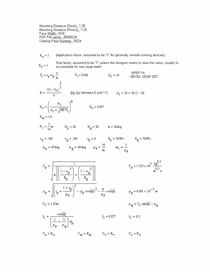
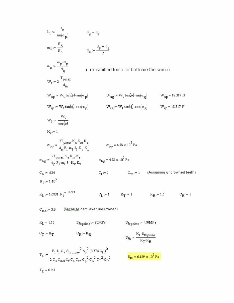
Bevel Gear Design Calculations
In the design of any bevel gear application, the forces exerted on the entire gear
train must be accounted for. Depending on the range of torque being transmitted into the
gears as well as the size and gear ratio of the application, the gears may experience a
tangential, radial, and axial force. The magnitudes of these forces are the primary
influence in designing the shaft strengths required and the bearings that must be used.
The design calculations used to select the proper shaft material, shaft diameter and
bearings for this senior design project can be found in Appendix I.
Senior Design Project
The purpose of this senior design project is to design and build a fully adjustable
bevel gear test bed for the Harris Corporation. Harris Corp. sponsored a similar senior
design project at a different university, but the bevel gears being tested failed sooner than
their expected life cycles. There are some possibilities as to why the previous system
failed to achieve the expected results. Some of these possibilities include overloading the
gears, misalignment in the gears, and/or a breakdown of the anodic coating on the surface
of the teeth causing the teeth to become abrasive. It is unlikely that any of these problems
were accounted for in the initial design calculations of the previous group, and it is part
of the scope of the current project to prevent these possible problems.
While trying to prevent the problems of the previous group is a concern, the initial
product specifications (Table 1) given by the sponsor of this project were quite
demanding. Due to budget restrictions and high degree of difficulty, the product
specifications were revised (Table 2). The primary difference between the initial and final
product specifications is the reduction of the motor torque and speed. Due to a budget
restriction of $1500.00, a set of motors to run at this specification is far too much for the
budget of this project.
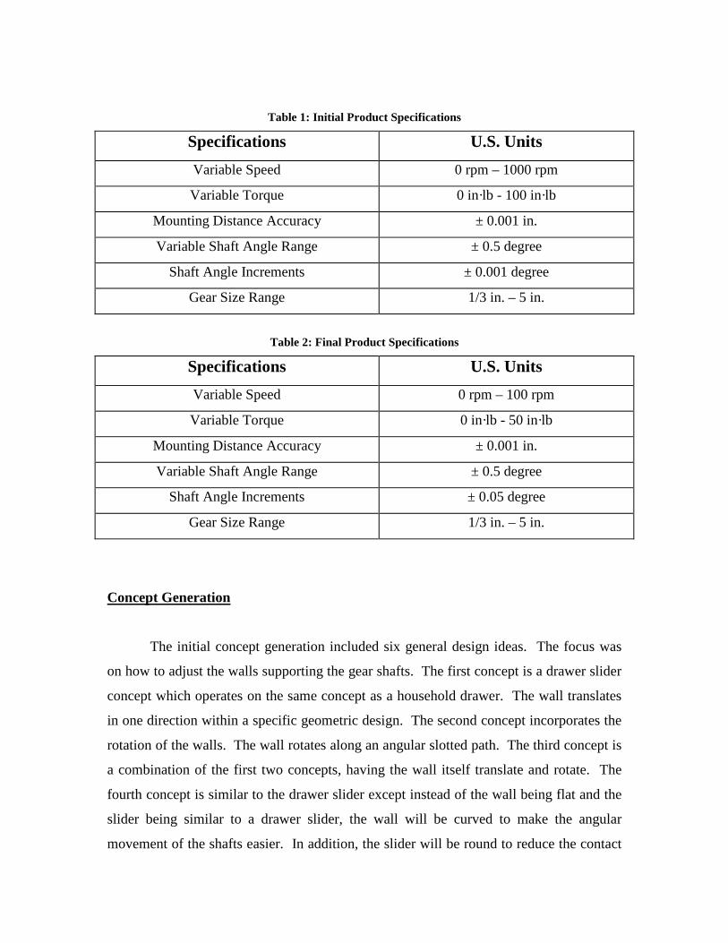
Table 1: Initial Product Specifications
Specifications U.S. Units
Variable Speed 0 rpm – 1000 rpm
Variable Torque 0 in·lb - 100 in·lb
Mounting Distance Accuracy ± 0.001 in.
Variable Shaft Angle Range ± 0.5 degree
Shaft Angle Increments ± 0.001 degree
Gear Size Range 1/3 in. – 5 in.
Table 2: Final Product Specifications
Specifications U.S. Units
Variable Speed 0 rpm – 100 rpm
Variable Torque 0 in·lb - 50 in·lb
Mounting Distance Accuracy ± 0.001 in.
Variable Shaft Angle Range ± 0.5 degree
Shaft Angle Increments ± 0.05 degree
Gear Size Range 1/3 in. – 5 in.
Concept Generation
The initial concept generation included six general design ideas. The focus was
on how to adjust the walls supporting the gear shafts. The first concept is a drawer slider
concept which operates on the same concept as a household drawer. The wall translates
in one direction within a specific geometric design. The second concept incorporates the
rotation of the walls. The wall rotates along an angular slotted path. The third concept is
a combination of the first two concepts, having the wall itself translate and rotate. The
fourth concept is similar to the drawer slider except instead of the wall being flat and the
slider being similar to a drawer slider, the wall will be curved to make the angular
movement of the shafts easier. In addition, the slider will be round to reduce the contact
area between the slider and surrounding material, thus reducing friction. The fifth
concept is a rack and pinion style design with two varying connection methods. The first
has a driving pinion and second a driven pinion. The last conceptual design is a worm
gear design where a worm gear is in mesh with a spur gear and will produce translational
motion of the walls.
Drawer-Slider
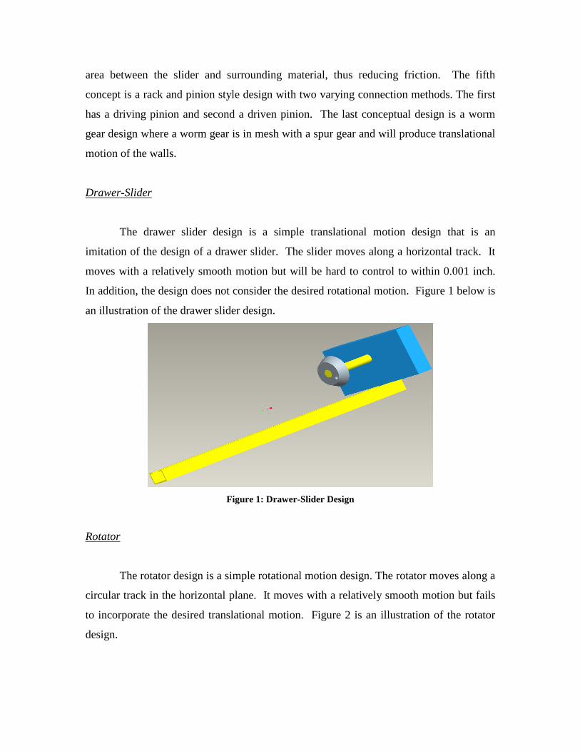
The drawer slider design is a simple translational motion design that is an
imitation of the design of a drawer slider. The slider moves along a horizontal track. It
moves with a relatively smooth motion but will be hard to control to within 0.001 inch.
In addition, the design does not consider the desired rotational motion. Figure 1 below is
an illustration of the drawer slider design.
Figure 1: Drawer-Slider Design
Rotator
The rotator design is a simple rotational motion design. The rotator moves along a
circular track in the horizontal plane. It moves with a relatively smooth motion but fails
to incorporate the desired translational motion. Figure 2 is an illustration of the rotator
design.
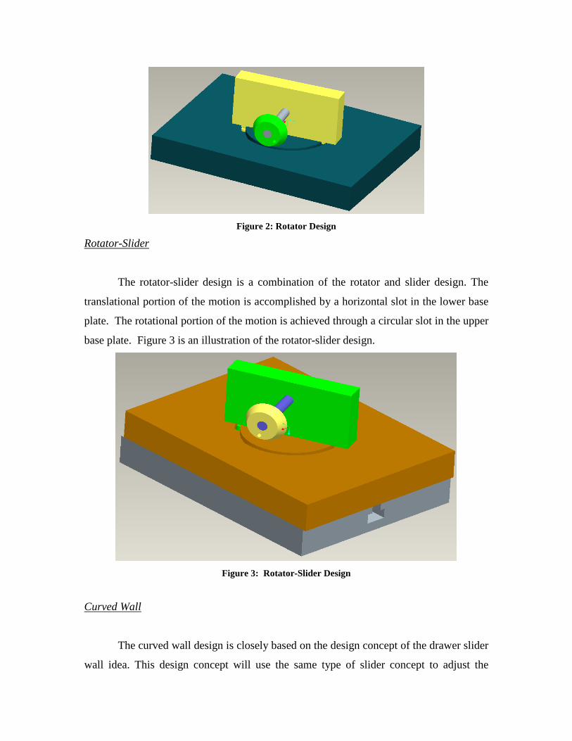
Figure 2: Rotator Design
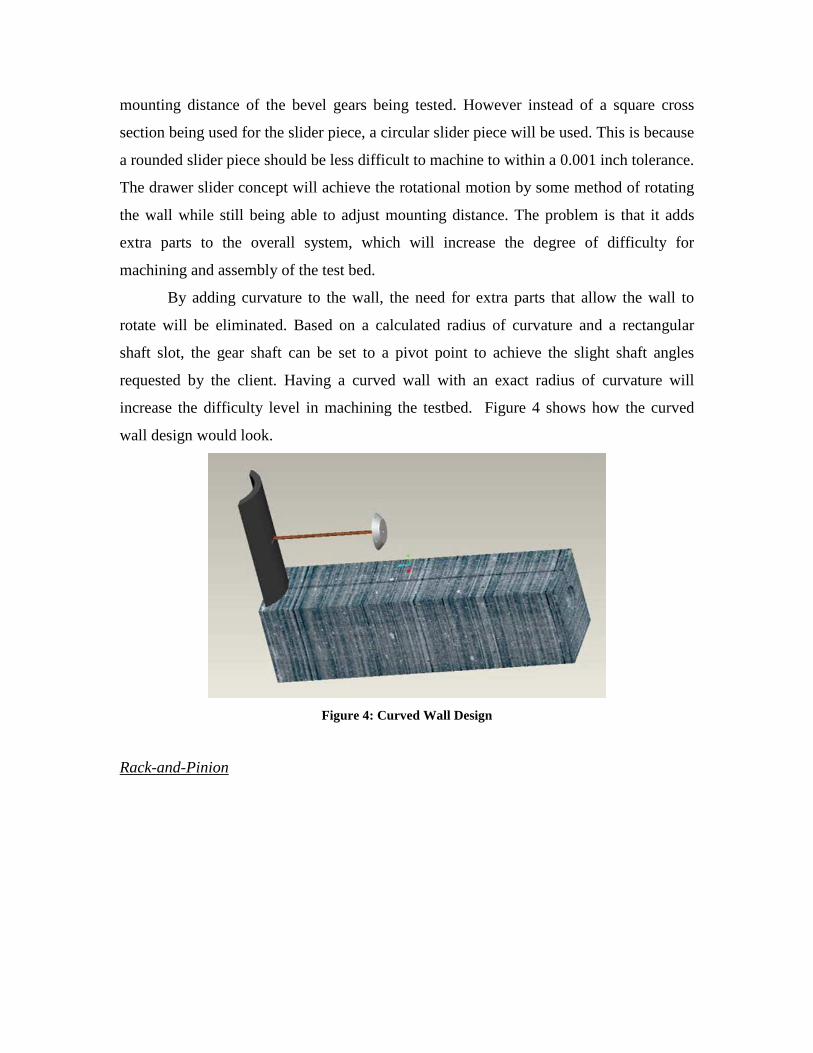
Rotator-Slider
The rotator-slider design is a combination of the rotator and slider design. The
translational portion of the motion is accomplished by a horizontal slot in the lower base
plate. The rotational portion of the motion is achieved through a circular slot in the upper
base plate. Figure 3 is an illustration of the rotator-slider design.
Figure 3: Rotator-Slider Design
Curved Wall
The curved wall design is closely based on the design concept of the drawer slider
wall idea. This design concept will use the same type of slider concept to adjust the
mounting distance of the bevel gears being tested. However instead of a square cross
section being used for the slider piece, a circular slider piece will be used. This is because
a rounded slider piece should be less difficult to machine to within a 0.001 inch tolerance.
The drawer slider concept will achieve the rotational motion by some method of rotating
the wall while still being able to adjust mounting distance. The problem is that it adds
extra parts to the overall system, which will increase the degree of difficulty for
machining and assembly of the test bed.
By adding curvature to the wall, the need for extra parts that allow the wall to
rotate will be eliminated. Based on a calculated radius of curvature and a rectangular
shaft slot, the gear shaft can be set to a pivot point to achieve the slight shaft angles
requested by the client. Having a curved wall with an exact radius of curvature will
increase the difficulty level in machining the testbed. Figure 4 shows how the curved
wall design would look.
Figure 4: Curved Wall Design
Rack-and-Pinion
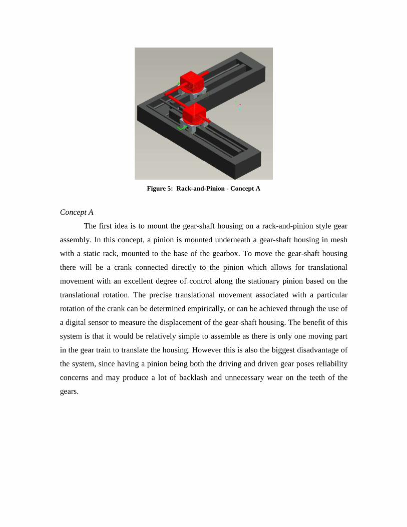
Figure 5: Rack-and-Pinion - Concept A
Concept A
The first idea is to mount the gear-shaft housing on a rack-and-pinion style gear
assembly. In this concept, a pinion is mounted underneath a gear-shaft housing in mesh
with a static rack, mounted to the base of the gearbox. To move the gear-shaft housing
there will be a crank connected directly to the pinion which allows for translational
movement with an excellent degree of control along the stationary pinion based on the
translational rotation. The precise translational movement associated with a particular
rotation of the crank can be determined empirically, or can be achieved through the use of
a digital sensor to measure the displacement of the gear-shaft housing. The benefit of this
system is that it would be relatively simple to assemble as there is only one moving part
in the gear train to translate the housing. However this is also the biggest disadvantage of
the system, since having a pinion being both the driving and driven gear poses reliability
concerns and may produce a lot of backlash and unnecessary wear on the teeth of the
gears.
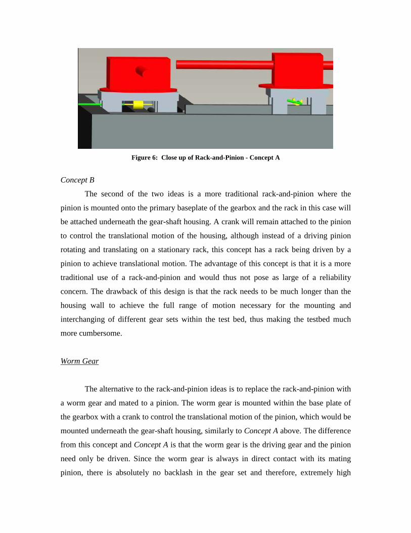
Figure 6: Close up of Rack-and-Pinion - Concept A
Concept B
The second of the two ideas is a more traditional rack-and-pinion where the
pinion is mounted onto the primary baseplate of the gearbox and the rack in this case will
be attached underneath the gear-shaft housing. A crank will remain attached to the pinion
to control the translational motion of the housing, although instead of a driving pinion
rotating and translating on a stationary rack, this concept has a rack being driven by a
pinion to achieve translational motion. The advantage of this concept is that it is a more
traditional use of a rack-and-pinion and would thus not pose as large of a reliability
concern. The drawback of this design is that the rack needs to be much longer than the
housing wall to achieve the full range of motion necessary for the mounting and
interchanging of different gear sets within the test bed, thus making the testbed much
more cumbersome.
Worm Gear
The alternative to the rack-and-pinion ideas is to replace the rack-and-pinion with
a worm gear and mated to a pinion. The worm gear is mounted within the base plate of
the gearbox with a crank to control the translational motion of the pinion, which would be
mounted underneath the gear-shaft housing, similarly to Concept A above. The difference
from this concept and Concept A is that the worm gear is the driving gear and the pinion
need only be driven. Since the worm gear is always in direct contact with its mating
pinion, there is absolutely no backlash in the gear set and therefore, extremely high
precision can be achieved with repeatability. The displacement associated with each
revolution of the crank can be determined empirically or via a digital sensor, both of
which would be simple enough to execute and as such, the digital sensor will most likely
be preferred, but most likely be extra strain on the budget.
The biggest advantage of the worm gear assembly over the rack-and-pinion
assembly is the repeatability of motion without compromising accuracy. Since there is no
backlash in the worm gear, interchanging and re-aligning different gears and/or shafts can
be done with a high degree of precision. The biggest disadvantage of the worm gear is
that it will likely cost more than the rack-and-pinion, since it requires its own bearings
and alignment, whereas the rack-and-pinion needs only one set of bearings for the pinion.
Despite these differences, both gear sets can provide highly accurate methods of
producing translational motion for the gear-shaft housing. However, the worm gear will
be more expensive.
Commercially Ordered Alignment Tables
Since the design and assembly of an alignment system is not only expensive, but
involves a high degree of precision, the best decision is to instead buy a commercially
available alignment table. Since the mounting distance accuracy is the driving factor, a
highly precise translational table is needed. To provide this type of precision alignment, a
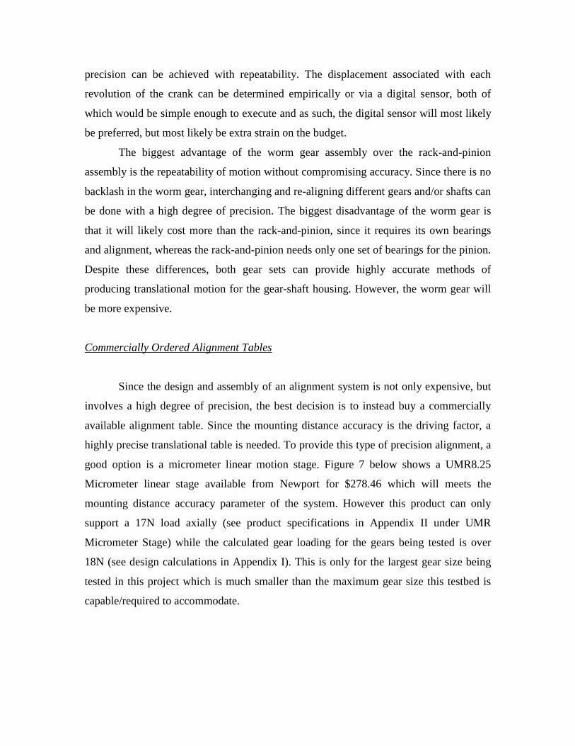
good option is a micrometer linear motion stage. Figure 7 below shows a UMR8.25
Micrometer linear stage available from Newport for $278.46 which will meets the
mounting distance accuracy parameter of the system. However this product can only
support a 17N load axially (see product specifications in Appendix II under UMR
Micrometer Stage) while the calculated gear loading for the gears being tested is over
18N (see design calculations in Appendix I). This is only for the largest gear size being
tested in this project which is much smaller than the maximum gear size this testbed is
capable/required to accommodate.
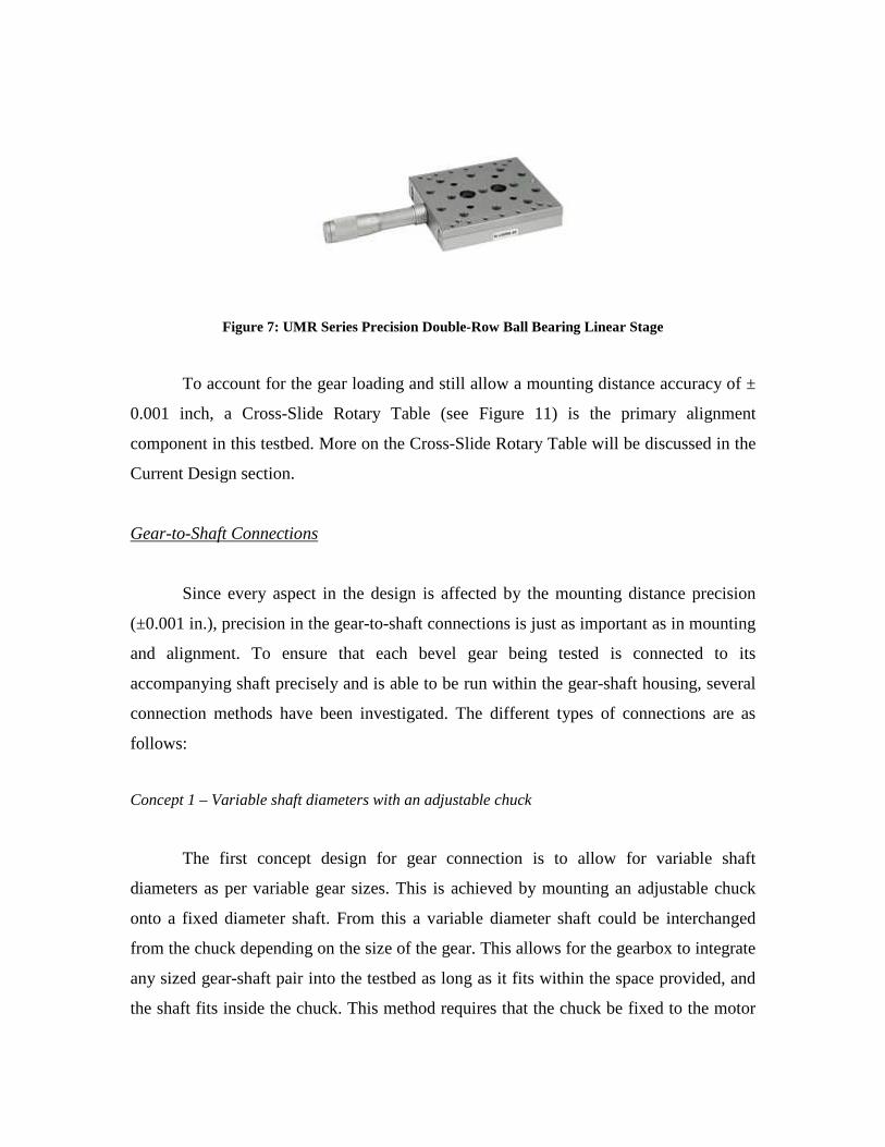
Figure 7: UMR Series Precision Double-Row Ball Bearing Linear Stage
To account for the gear loading and still allow a mounting distance accuracy of ±
0.001 inch, a Cross-Slide Rotary Table (see Figure 11) is the primary alignment
component in this testbed. More on the Cross-Slide Rotary Table will be discussed in the
Current Design section.
Gear-to-Shaft Connections
Since every aspect in the design is affected by the mounting distance precision
(±0.001 in.), precision in the gear-to-shaft connections is just as important as in mounting
and alignment. To ensure that each bevel gear being tested is connected to its
accompanying shaft precisely and is able to be run within the gear-shaft housing, several
connection methods have been investigated. The different types of connections are as
follows:
Concept 1 – Variable shaft diameters with an adjustable chuck
The first concept design for gear connection is to allow for variable shaft
diameters as per variable gear sizes. This is achieved by mounting an adjustable chuck
onto a fixed diameter shaft. From this a variable diameter shaft could be interchanged
from the chuck depending on the size of the gear. This allows for the gearbox to integrate
any sized gear-shaft pair into the testbed as long as it fits within the space provided, and
the shaft fits inside the chuck. This method requires that the chuck be fixed to the motor
and inside a large accompanying bearing to account for the added weight of the chuck, to
ensure reliability. This is a very simple method of interchanging different sized shafts.
The biggest drawback for this idea is the precision of the chuck, since it is unlikely that it
would be precise to 0.001 inch, thus ruining the alignment of the gears. Upon further
investigation, it is decided that a high precision chuck would be quite difficult to find and
afford, while the manufacturing of a custom chuck would be much too complex and time-
consuming for the group to take on.
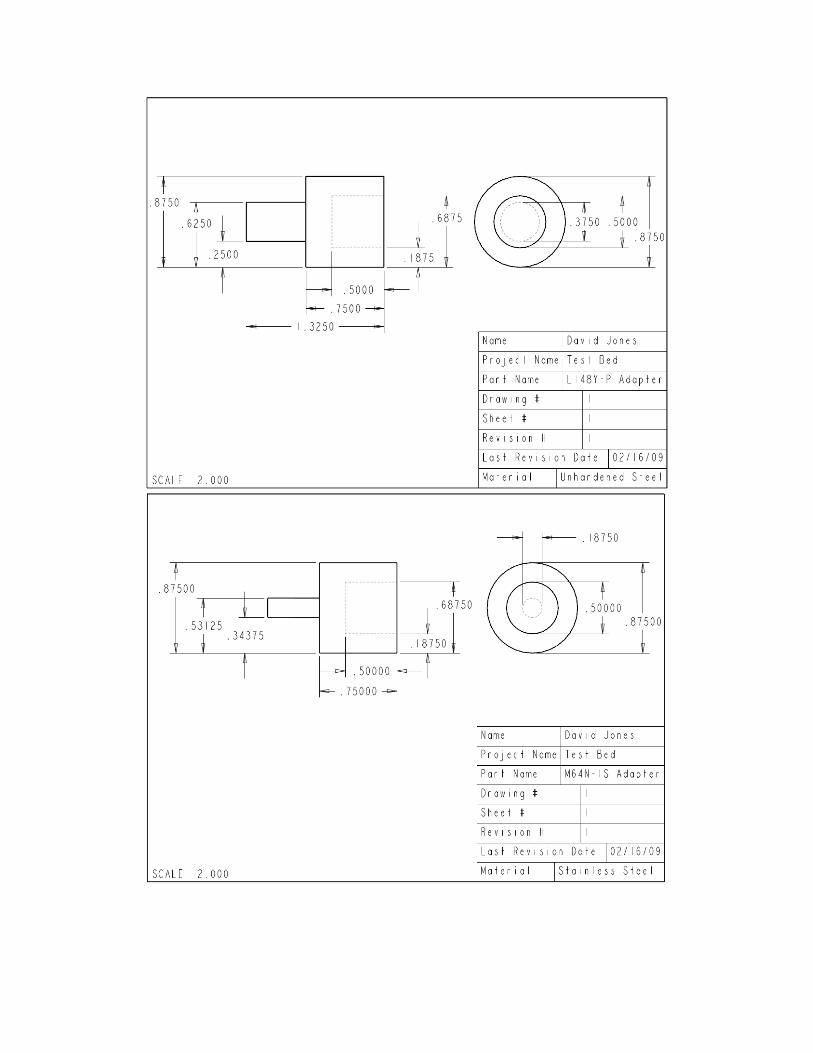
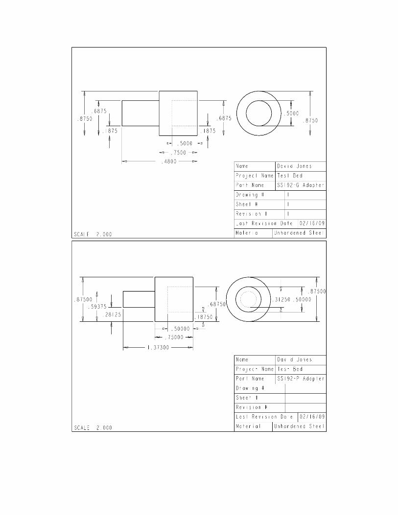
Concept 2 – Constant shaft diameter with variable shaft adapters
The second concept is to use a constant diameter large stock shaft and
supplementary bearings. Variable diameter adapters are machined to mount onto the
input and output shafts to fit any size bevel gear being tested, as shown in Figure 8
below. This method requires that a new adapter be machined for each size gear-shaft to
be tested, which costs time and money; however it is less costly in terms of both time and
money than designing and manufacturing of an adjustable chuck. In addition, if done
properly, this method should be much more accurate than an adjustable chuck.
Figure 8: Gear to Shaft Adapters
The idea is to drill a tapped hole into the adapter with an accompanying flat section
on the shaft that connects by way of a set screw. This approach will be simple to machine
and can be machined to the required accuracy.
The most likely approach is to go with Concept 2 since it will be simplest to
assemble, and is also the most reliable without too much unnecessary cost. It will be very
rigid, and the mounting distance is capable of being controlled to the necessary tolerance.
It also is not very expensive in comparison to purchasing or machining a chuck, and
allows for variable gear-shaft sizes.
Current Design
The current design is much more intricate than the initial concept designs. This is
expected however. A detailed explanation of the primary componentry required to meet
the design parameters is explained below with a labeled image of the finished testbed at
the end of the section.
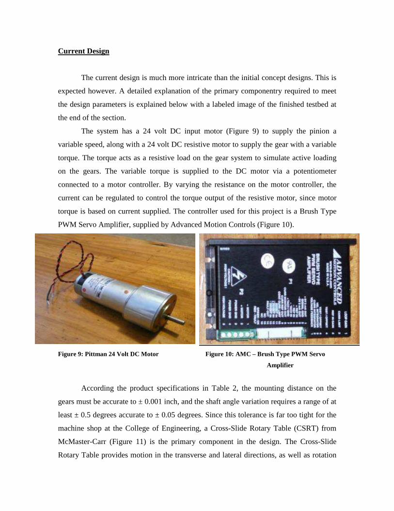
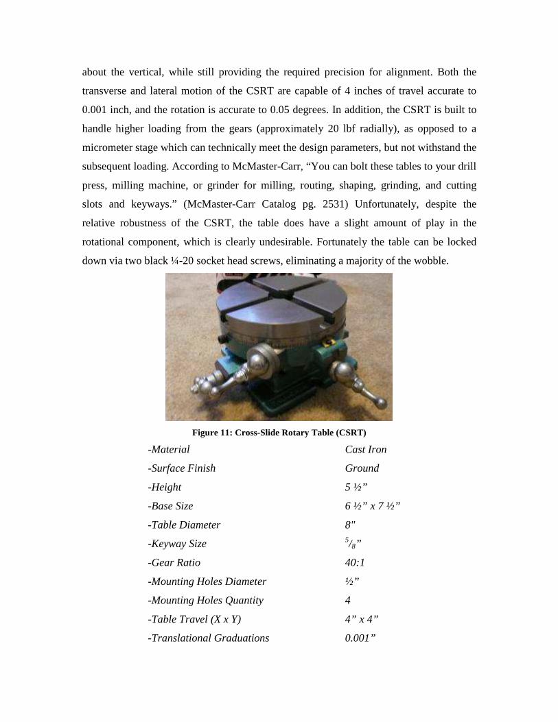
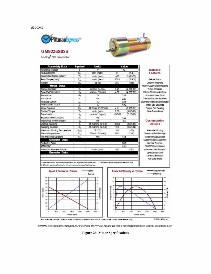
The system has a 24 volt DC input motor (Figure 9) to supply the pinion a
variable speed, along with a 24 volt DC resistive motor to supply the gear with a variable
torque. The torque acts as a resistive load on the gear system to simulate active loading
on the gears. The variable torque is supplied to the DC motor via a potentiometer
connected to a motor controller. By varying the resistance on the motor controller, the
current can be regulated to control the torque output of the resistive motor, since motor
torque is based on current supplied. The controller used for this project is a Brush Type
PWM Servo Amplifier, supplied by Advanced Motion Controls (Figure 10).
Figure 9: Pittman 24 Volt DC Motor Figure 10: AMC – Brush Type PWM Servo
Amplifier
According the product specifications in Table 2, the mounting distance on the
gears must be accurate to ± 0.001 inch, and the shaft angle variation requires a range of at
least ± 0.5 degrees accurate to ± 0.05 degrees. Since this tolerance is far too tight for the
machine shop at the College of Engineering, a Cross-Slide Rotary Table (CSRT) from
McMaster-Carr (Figure 11) is the primary component in the design. The Cross-Slide
Rotary Table provides motion in the transverse and lateral directions, as well as rotation
about the vertical, while still providing the required precision for alignment. Both the
transverse and lateral motion of the CSRT are capable of 4 inches of travel accurate to
0.001 inch, and the rotation is accurate to 0.05 degrees. In addition, the CSRT is built to
handle higher loading from the gears (approximately 20 lbf radially), as opposed to a
micrometer stage which can technically meet the design parameters, but not withstand the
subsequent loading. According to McMaster-Carr, “You can bolt these tables to your drill
press, milling machine, or grinder for milling, routing, shaping, grinding, and cutting
slots and keyways.” (McMaster-Carr Catalog pg. 2531) Unfortunately, despite the
relative robustness of the CSRT, the table does have a slight amount of play in the
rotational component, which is clearly undesirable. Fortunately the table can be locked
down via two black ¼-20 socket head screws, eliminating a majority of the wobble.
Figure 11: Cross-Slide Rotary Table (CSRT)
-Material Cast Iron
-Surface Finish Ground
-Height 5 ½”
-Base Size 6 ½” x 7 ½”
-Table Diameter 8"
-Keyway Size 5/8”
-Gear Ratio 40:1
-Mounting Holes Diameter ½”
-Mounting Holes Quantity 4
-Table Travel (X x Y) 4” x 4”
-Translational Graduations 0.001”
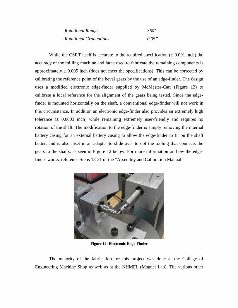
-Rotational Range 360º
-Rotational Graduations 0.05”
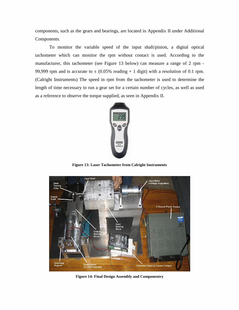
While the CSRT itself is accurate to the required specification (± 0.001 inch) the
accuracy of the milling machine and lathe used to fabricate the remaining components is
approximately ± 0.005 inch (does not meet the specifications). This can be corrected by
calibrating the reference point of the bevel gears by the use of an edge-finder. The design
uses a modified electronic edge-finder supplied by McMaster-Carr (Figure 12) to
calibrate a local reference for the alignment of the gears being tested. Since the edge-
finder is mounted horizontally on the shaft, a conventional edge-finder will not work in
this circumstance. In addition an electronic edge-finder also provides an extremely high
tolerance (± 0.0003 inch) while remaining extremely user-friendly and requires no
rotation of the shaft. The modification to the edge-finder is simply removing the internal
battery casing for an external battery casing to allow the edge-finder to fit on the shaft
better, and is also inset in an adapter to slide over top of the tooling that connects the
gears to the shafts, as seen in Figure 12 below. For more information on how the edge-
finder works, reference Steps 18-21 of the “Assembly and Calibration Manual”.
Figure 12: Electronic Edge-Finder
The majority of the fabrication for this project was done at the College of
Engineering Machine Shop as well as at the NHMFL (Magnet Lab). The various other
components, such as the gears and bearings, are located in Appendix II under Additional
Components.
To monitor the variable speed of the input shaft/pinion, a digital optical
tachometer which can monitor the rpm without contact is used. According to the
manufacturer, this tachometer (see Figure 13 below) can measure a range of 2 rpm -
99,999 rpm and is accurate to ± (0.05% reading + 1 digit) with a resolution of 0.1 rpm.
(Calright Instruments) The speed in rpm from the tachometer is used to determine the
length of time necessary to run a gear set for a certain number of cycles, as well as used
as a reference to observe the torque supplied, as seen in Appendix II.
Figure 13: Laser Tachometer from Calright Instruments
Figure 14: Final Design Assembly and Componentry

Cost Analysis
Upon completion of the initial design, the project exceeded the budget by more
than $500.00. The majority of this cost was based on purchasing gears, motors, and
micrometer translational stages. To correct this problem, Harris Corp. was able to supply
three gear sets and several motors for free. In addition this, the micrometer translation
tables were removed from the design, in favor of the Cross-Slide Rotary Table, which is
significantly less expensive than a set of micrometer stages. As can be seen in Figure 15
below, the project is currently under budget, including all of the necessary components.
Figure 15: Cost Analysis Summary
Testing and Analysis
Due to the time constraints in fabricating and assembling the testbed, little to no
parametric testing has been done at present. The majority of the testing done thus far is
essentially troubleshooting. Ensuring that the assembly components work/fit as expected
and that the gears can be run in mesh is the primary concern of testing presently, although
no data has been collected thus far. Additionally the shaft axes have been properly
aligned to exactly ninety degrees using an edge-feeler gauge accurate to ± 0.0005 inch
(well within the angular precision of ± 0.005 inch). As such an addendum will be
submitted at a later date with more conclusive data comparing the testbed results to the
product specifications.
Determining the resistive torque load on the gears, the motor controller must
supply the resistive motor with a controlled variable current. To determine the total
resistive load on the gears, a combination of resistance loads are combined. Even when
the resistive motor is not resisting the rotation of the gears, there is still a resistive load
associated with turning a shaft against a motor. This resistive load is determined by
balancing a beam of known radius with a known mass attached to the end of it, to
determine the torque required to turn the shaft inside the motor. This is the unloaded
resistance of the system. When the resistive motor is running however, there is
significantly more resistive loading on the gears, which is difficult to quantify
empirically. This can be done however by using a Torque vs. Current and RPM plot
supplied by the motor manufacturer which is located in Appendix II. Combining these
two loads yields the total resistive torque applied to the gears.
Propositions for Improvement
Precision Alignment Resolution
A major concern in the fabrication of this testbed is the propagation of error in the
individual components. Each machined component is accurate to ~ ± 0.005 inch. This
deviation compounds with every piece attached to another, resulting in a tolerance well
outside the range deemed acceptable for this design. To combat this problem, an edge-
finder is used to minimize the error propagation in the transverse and lateral (x and y)
directions, however any deviation from alignment in the vertical is controlled only by the
accuracy of the machining process. There are a number of things capable of improving
the alignment resolution, and are described as follows.
One of the simplest and cheapest improvements to the alignment precision would
be to plane every surface of every component used to construct the testbed. Many of the
raw materials received were assumed to be flat, based on the look and feel of the cut.
Instead of taking this assumption as relative truth, it would have been beneficial to
properly face each surface of the components from the original material stock. A prime
example of this is the baseplate, which is made of solid aluminum, ½ inch thick. The
baseplate appears to have planar surfaces, but after considerable study it can be seen that
it is in fact somewhat warped. Regardless of this and several other flaws in the materials,
all of the components still fit together and appear to operate smoothly. It is because of
this reason that the problem posed by this is hard to quantify, but it is likely that this
concern can eventually become problematic after long duration tests at high loading.
Another possible improvement in the alignment resolution is to try to replace
several parts connected together with one solid piece of stock. This also is not too
expensive of a design option, though still more expensive, but would have been much
more difficult to do based on the geometry of the testbed. The input assembly especially
would have been hard to fabricate as such a large piece of material out of one solid piece.
The difficulty in this is rather large, in addition to increased cost, since the majority of the
current bed is made from recycled material stock. This method, although more accurate,
is more expensive in terms of adding more wasted material to the budget, and less
practical due to increased degree of difficulty in machining.
A third improvement to the fabrication precision is to incorporate alignment pins
into the assembly process. Since alignment pins align components to an extremely high
precision, the uncertainty in the assembly precision is greatly reduced. This is because
without the use of alignment pins, the components are aligned only by the surfaces and
screws holding them together. Conversely with alignment pins the components are still
held together by the screws, but the screws/threads are not used for alignment, only
rigidity. While it is usually hard to visibly notice any misalignment from screw-based
alignment, there is a pre-determined acceptable amount or error in screws/threads, which
can cause mild deviations from the design alignment. Alignment pins have a much tighter
tolerance than any screw threads and as such are a much more precise method of aligning
components.
The single greatest improvement to the precision alignment resolution is to build
the entire testbed on more accurate machinery. If enough of the budget was allotted to
outsourcing the machine work to a shop with more precise tolerances, the components in
the system would have higher precision. The best case scenario would be for each of the
components to be fabricated on an automated CNC milling machine, since these
machines usually have the highest precision, because they eliminate user error.
Essentially the best, yet most expensive, way to improve the alignment precision is to
have a more experienced machinist with better equipment fabricate the design.
Independent X – Y Translation Slides
A major flaw in the current testbed is the inability to rotate the gear alignment
about the pitch cone center (PCC). This is a result of the method of manually positioning
the gears for alignment, by use of the Cross-Slide Rotary Table. The CSRT is the primary
component in the design of this testbed because it can handle the maximum gear loading
with relative ease, while still meeting the alignment criteria and fitting well into the
budget. The problem with the table is that only the output assembly can move, therefore
unless the PCC is perfectly aligned with the center of the rotary table, any rotation of the
gears will be non-uniform. Basically since the purpose of the rotary component in the
design is to allow for controlled misalignment in testing, and the PCC might not always
line up over center, then it is very hard to control that misalignment. To improve this, the
best approach is to provide translational motion independently for the input and output
assemblies, with one of the two having a rotational component. This requires two linear
stages each with only one direction of travel and one rotary table, able to connect in some
manner to one of the linear stages. In addition, each of these motion tables must be able
to withstand the maximum gear forces and have a method of locking down once aligned,
unless there is significant resistance to back-driving forces. This is a feasible
improvement, but based on the budget of the project it is too expensive to provide such a
system of motion
Increased RPM and Resistive Torque:
While the speed and torque requirements on this project had to be greatly reduced
on account of the budget limitations, realistically Harris requires specifications on the
order of the initial requirements (speed x 10 and torque x 2) to obtain testing results
worth obtaining. This is a simple fix however, requiring little more than the funding to
purchase a more powerful motor and perhaps redesigned motor mounts to fit the new
motor.
Increased Range of Gear Sizes:
Due to the total translational displacement of the CSRT, the range of gear sizes
capable of being tested is limited. By implementing a larger translation table the gear size
range for testing increases. This would require a larger budget and more time to integrate
the new table into the current design. The range of gear sizes able to be tested currently
just barely meets the product specifications on the larger end (~5.0 inch).
Possible Future Plans
There are a few additions that can be added to the test bed to make it more useful
in testing for a wide range of common gearing problems. Due to a very tight budget, the
main objective for this project is to design, fabricate and assemble a fully adjustable
bevel gear testbed to operate to tight mounting specifications and variable speed and
loading requirements. Anything beyond this scope is an extended goal, and as such is
more of a future consideration than a concern of this project. Additionally the budget of
the project does not adequately accommodate the implementation of the following.
Vibration Testing:
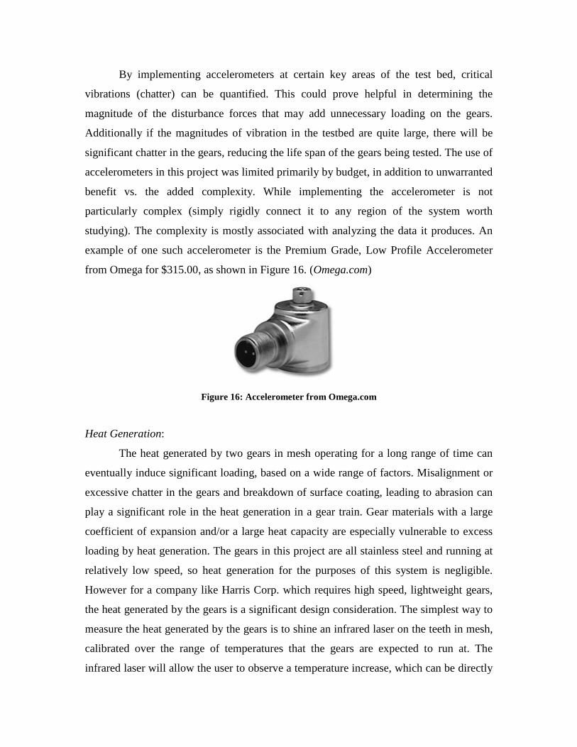
By implementing accelerometers at certain key areas of the test bed, critical
vibrations (chatter) can be quantified. This could prove helpful in determining the
magnitude of the disturbance forces that may add unnecessary loading on the gears.
Additionally if the magnitudes of vibration in the testbed are quite large, there will be
significant chatter in the gears, reducing the life span of the gears being tested. The use of
accelerometers in this project was limited primarily by budget, in addition to unwarranted
benefit vs. the added complexity. While implementing the accelerometer is not
particularly complex (simply rigidly connect it to any region of the system worth
studying). The complexity is mostly associated with analyzing the data it produces. An
example of one such accelerometer is the Premium Grade, Low Profile Accelerometer
from Omega for $315.00, as shown in Figure 16. (Omega.com)
Figure 16: Accelerometer from Omega.com
Heat Generation:
The heat generated by two gears in mesh operating for a long range of time can
eventually induce significant loading, based on a wide range of factors. Misalignment or
excessive chatter in the gears and breakdown of surface coating, leading to abrasion can
play a significant role in the heat generation in a gear train. Gear materials with a large
coefficient of expansion and/or a large heat capacity are especially vulnerable to excess
loading by heat generation. The gears in this project are all stainless steel and running at
relatively low speed, so heat generation for the purposes of this system is negligible.
However for a company like Harris Corp. which requires high speed, lightweight gears,
the heat generated by the gears is a significant design consideration. The simplest way to
measure the heat generated by the gears is to shine an infrared laser on the teeth in mesh,
calibrated over the range of temperatures that the gears are expected to run at. The
infrared laser will allow the user to observe a temperature increase, which can be directly
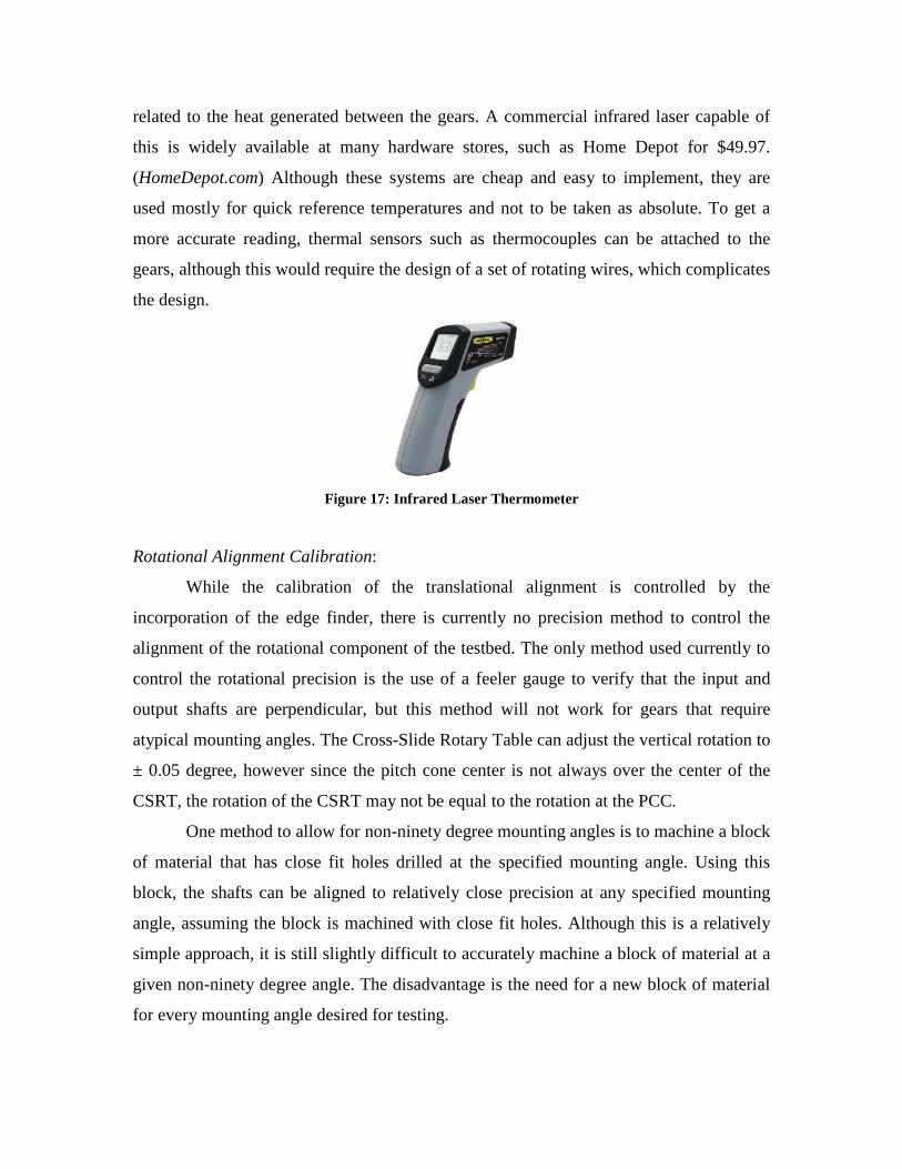
related to the heat generated between the gears. A commercial infrared laser capable of
this is widely available at many hardware stores, such as Home Depot for $49.97.
(HomeDepot.com) Although these systems are cheap and easy to implement, they are
used mostly for quick reference temperatures and not to be taken as absolute. To get a
more accurate reading, thermal sensors such as thermocouples can be attached to the
gears, although this would require the design of a set of rotating wires, which complicates
the design.
Figure 17: Infrared Laser Thermometer
Rotational Alignment Calibration:
While the calibration of the translational alignment is controlled by the
incorporation of the edge finder, there is currently no precision method to control the
alignment of the rotational component of the testbed. The only method used currently to
control the rotational precision is the use of a feeler gauge to verify that the input and
output shafts are perpendicular, but this method will not work for gears that require
atypical mounting angles. The Cross-Slide Rotary Table can adjust the vertical rotation to
± 0.05 degree, however since the pitch cone center is not always over the center of the
CSRT, the rotation of the CSRT may not be equal to the rotation at the PCC.
One method to allow for non-ninety degree mounting angles is to machine a block
of material that has close fit holes drilled at the specified mounting angle. Using this
block, the shafts can be aligned to relatively close precision at any specified mounting
angle, assuming the block is machined with close fit holes. Although this is a relatively
simple approach, it is still slightly difficult to accurately machine a block of material at a
given non-ninety degree angle. The disadvantage is the need for a new block of material
for every mounting angle desired for testing.
The best method to align the rotational component of the assembly is to use a
professional alignment system. Modern professional systems use laser alignment for
precision that typically cannot be replicated with mechanical components. These systems
are well outside of the budget of this project, but can vastly improve the precision well
above the required specifications in both manufacturing and alignment.
Conclusion
While fabrication of the testbed is finished and most of the design parameters are
met, the conclusive results are limited. This is largely due to the lack of physical data and
some unresolved issues. Calibrating the reference origin for the input and output shafts
using the edge-finder and controlling and quantifying the resistive motor torque are the
main unresolved issues at present. Data acquisition is primarily dependent on solving the
motor controller problem.
Using the edge-finder to calibrate the x-y translational reference locations (the
origin) is unresolved simply because the edge-finder bulb failed due to a short in the
ground wire terminal after it was modified to fit the testbed. Since the bulb cannot be
replaced, a replacement edge-finder is currently in transit. Once the new edge-finder is
obtained, this will be a non-issue as long as more care is taken to electrically insulate the
terminals.
To control the resistive torque according to the parameter specifications, the
motor controller uses a potentiometer which is essentially a variable resistor, by varying
the current supplied to the resistive motor. Unfortunately, the most recent test of the
controller was unsuccessful in providing a variable current by means of a varying
resistance. Essentially the potentiometer resistance was adjusted with no change in
current supplied to the resistive motor. To solve this problem, the controller vender,
Advanced Motion Controls, will be contacted for further technical support. Additionally
the quantification of the torque load supplied to the gears by the resistive motor is
provided in the method described in the Testing and Analysis section of this report. This
however is dependent on solving the issue in operating the motor controller.
The data collection is scheduled to take place this weekend and the days leading
up to open house. As stated in the Testing and Analysis section, an addendum will be
provided at a later date, providing empirical data comparing various runs of the gears,
including loaded and unloaded gear trials (pending motor controller functionality), and
life cycle testing. The gears have been run for an indefinite length of time (~3 hours) and
have run quite smooth, without considering any of the specific parameters other than
verifying the rpm with the optical tachometer. This is solely for the knowledge that the
system works as well as troubleshooting, rather than trying to provide any substantial
data.
As previously stated a majority of the design specifications (Table 2) are
accounted for in the fabricated testbed. The variable speed (0-100 rpm), variable shaft
angle range (± 0.5 degree), shaft angle accuracy (± 0.05 degree) and gear size range (1/3
in. – 5 in.) are all attainable in the current system. Only the variable torque (0 in·lb - 50
in·lb) and mounting distance accuracy (± 0.001 in.) have yet to be met. The torque
specification has yet to be met on account of the problems with the motor controller,
discussed previously. There is a strong belief however that once the motor controller is
wired properly and its operation fully understood, that this requirement will be met.
The deviation in the mounting distance accuracy is primarily the result of error
propagation in the componentry. The linear translation tables on the CSRT are accurate to
± 0.001 inch in each direction. This is just the accuracy of the table itself and does not
account for the accuracy of the edge-finder which is used in conjunction with the CSRT
to reference the local origins of the translational axes. If the edge-finder accuracy is
included (± 0.0003 in.) and using the root of the squares of these accuracies is considered,
the total mounting distance accuracy is ± 0.001044 inch. While this is a very tight
tolerance for the purpose of testing gears in the speed and torque range of this project, it
is still outside the specifications from the sponsor. This is due in large part to budget
driven design. Since the Cross-Slide Rotary Table by itself just barely exceeds the
mounting distance specification of the project, this table cannot be used to meet this
parameter. However, this table is approved by the sponsor (Brent Stancil) since it is the
only table found that can approximate the accuracy requirements while still handle the
gear loads and remain within the budget for the project.

Despite the various parametric constraints in the design and development of this
project, a majority of the design parameters have been met and a fully functional testbed
is ready for submission. In addition, an addendum will be submitted before Open House
to provide more information on the experimental results of the testbed and how it meets
life cycle expectations. This is a very challenging problem and a great deal has been
learned in designing, developing and troubleshooting this project, in addition to providing
an excellent opportunity to practice semi-formal, industry-type presentations and progress
reports.
Acknowledgements
Dr. Hollis
- Calculations Review
- Design guidance
Brent Stancil
- Providing the motors and gear sets
- Clarifying critical specifications
- Teleconference meetings for further design guidance
Keith Larson / Cody Epperson
- Machining Assistance
- Machining Guidance
Dr. Englander
- Providing DC Power Supply
Richard Robards
- Pro-E assistance
- Supply of miscellaneous hardware
- Machining Assistance
Angela Scharnetski / Rene Ymzon
- Providing a student discount on the controller
- Controller application and implementation guidanc

References
1. Harris history and background: http://www.harris.com/company-history.html
2. General gear information: http://science.howstuffwork.com/gear4.htm
3. Rotary Table Information: http://www.mcmaster.com/#rotary-tables/=1bx20r
4. Accelerometer Information:
http://www.omega.com/ppt/pptsc.asp?ref=ACC797&Nav=prek02
5. Gear Ordering Information: http://www.bostongear.com
6. Gear Ordering Information: http://www.wmberg.com
7. Tachometer Ordering Information: http://www.calright.com/pd_1055.aspx
8. Infrared Laser Thermometer:
http://www.homedepot.com/webapp/wcs/stores/servlet/ProductDisplay?storeId=1
0051&langId=-1&catalogId=10053&productId=100651817&N=10000003+9040
1+500061
Appendix I
Design Calculations:
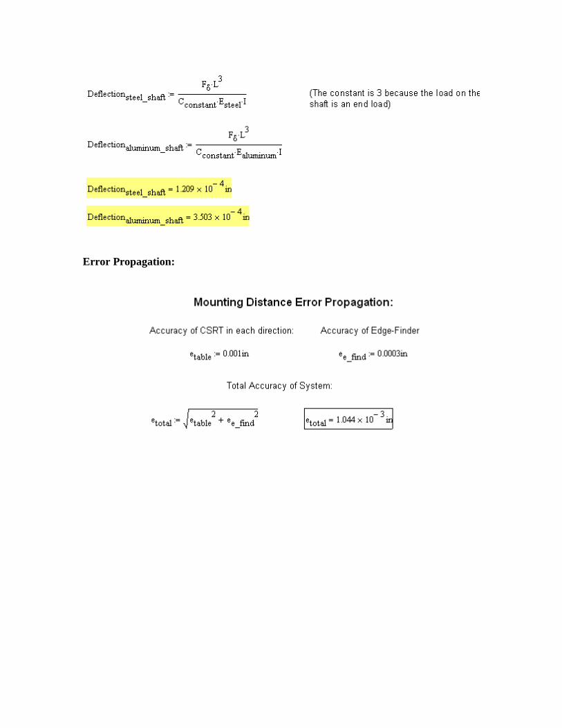
Error Propagation:
Appendix II
Additional Components:
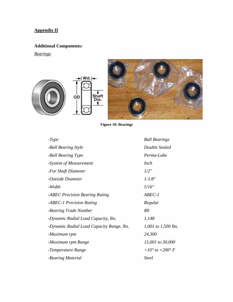
Bearings
Figure 18: Bearings
-Type Ball Bearings
-Ball Bearing Style Double Sealed
-Ball Bearing Type Perma-Lube
-System of Measurement Inch
-For Shaft Diameter 1/2"
-Outside Diameter 1-1/8"
-Width 5/16"
-ABEC Precision Bearing Rating ABEC-1
-ABEC-1 Precision Rating Regular
-Bearing Trade Number R8
-Dynamic Radial Load Capacity, lbs. 1,148
-Dynamic Radial Load Capacity Range, lbs. 1,001 to 1,500 lbs.
-Maximum rpm 24,300
-Maximum rpm Range 15,001 to 30,000
-Temperature Range +10° to +200° F
-Bearing Material Steel
-Seal Material Buna-N
-Specifications Met Not Rated
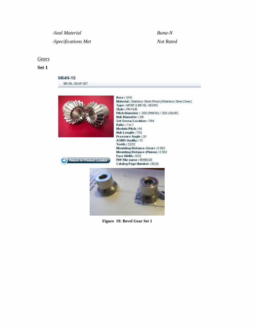
Gears
Set 1
Figure 19: Bevel Gear Set 1
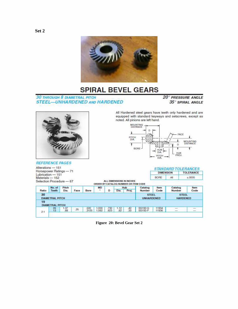
Set 2
Figure 20: Bevel Gear Set 2
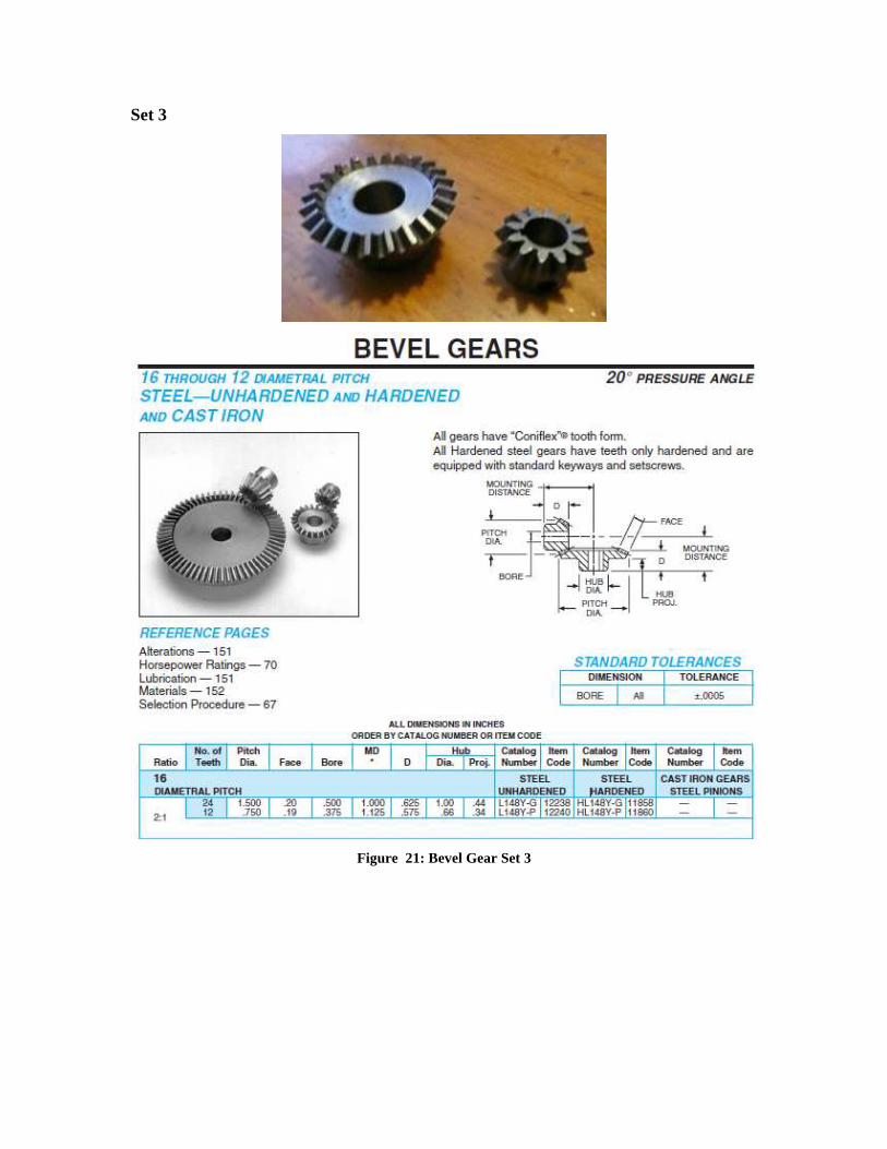
Set 3
Figure 21: Bevel Gear Set 3
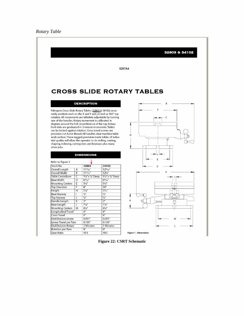
Rotary Table
Figure 22: CSRT Schematic
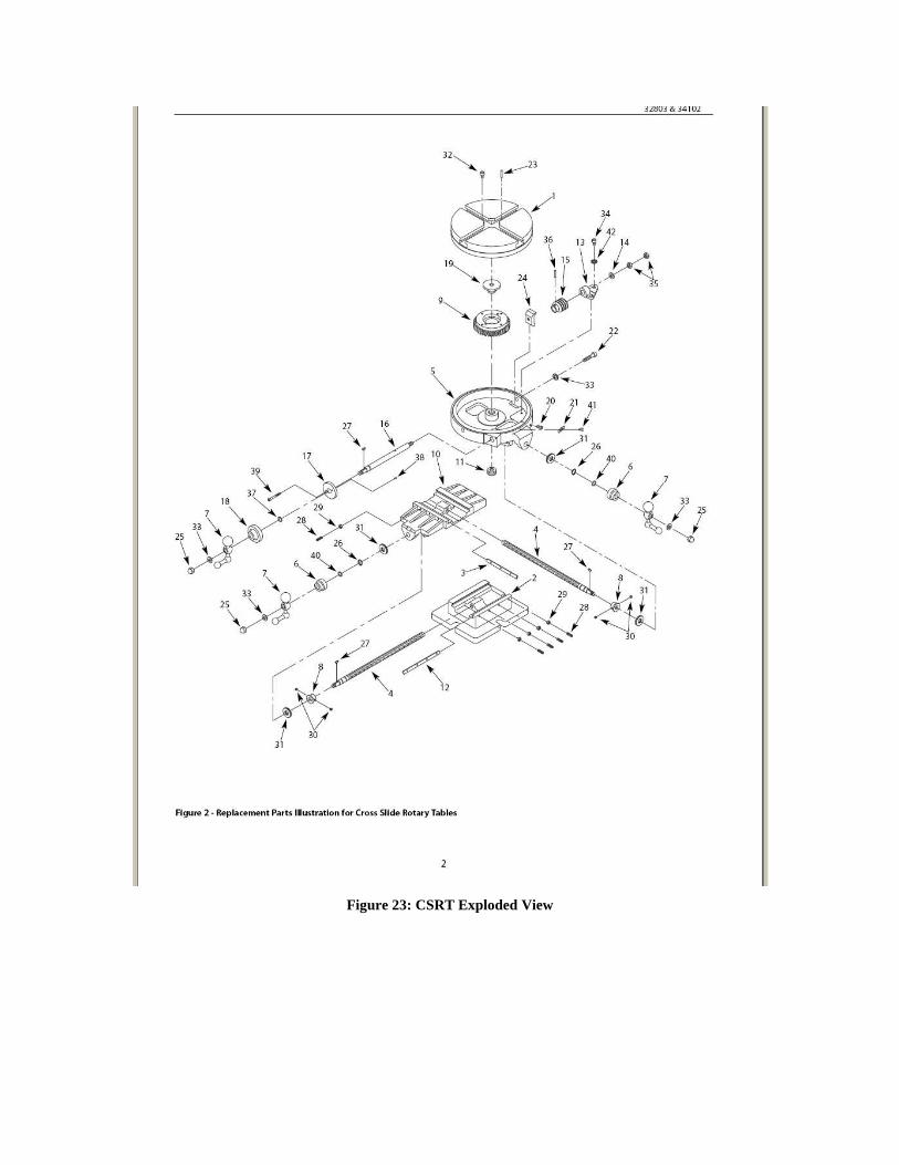
Figure 23: CSRT Exploded View
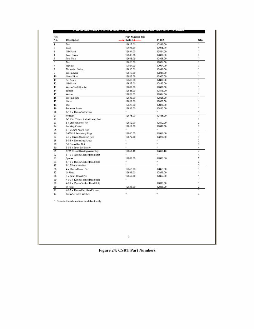
Figure 24: CSRT Part Numbers
Motors
Figure 25: Motor Specifications
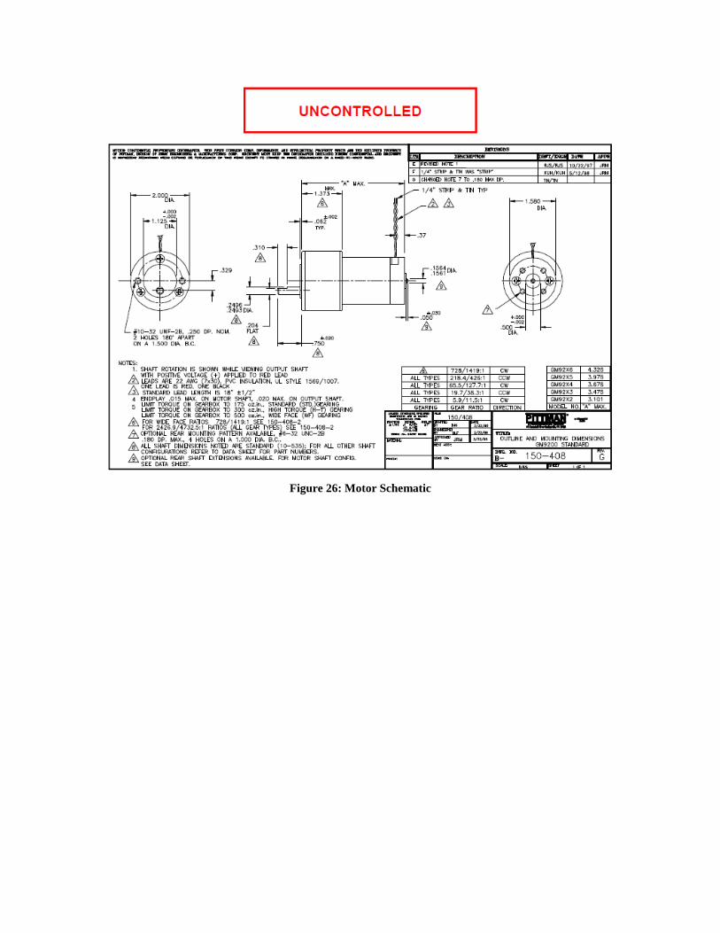
Figure 26: Motor Schematic
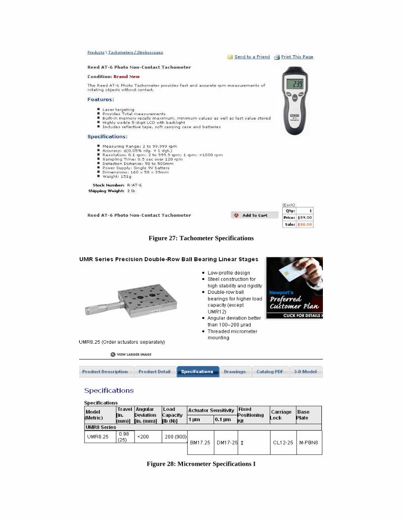
Figure 27: Tachometer Specifications
Figure 28: Micrometer Specifications I
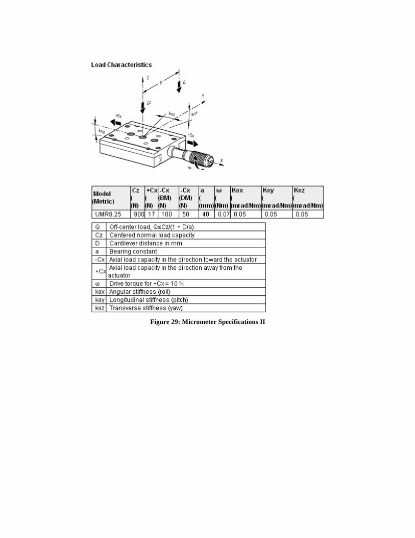
Figure 29: Micrometer Specifications II
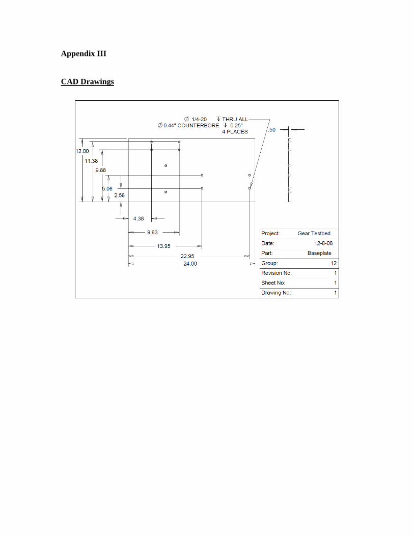
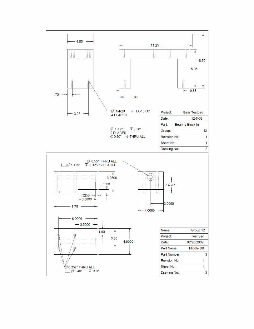
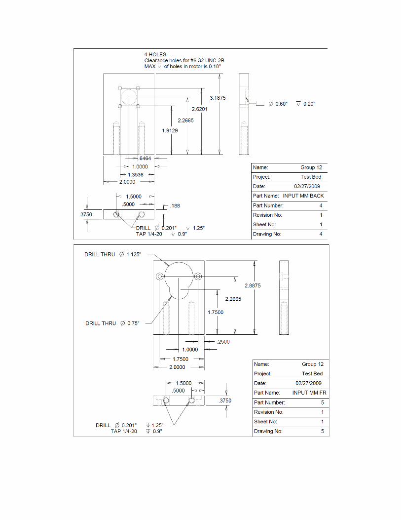
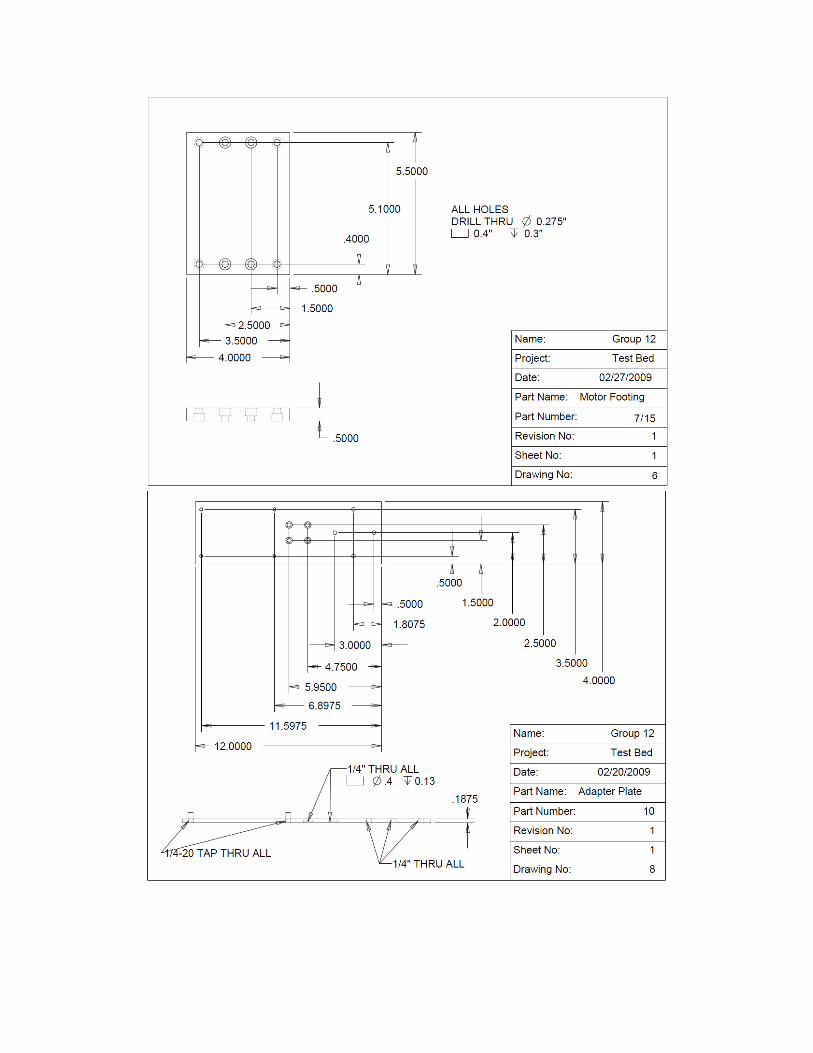
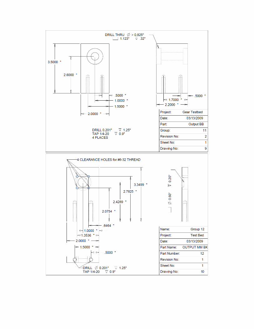
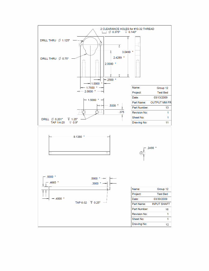
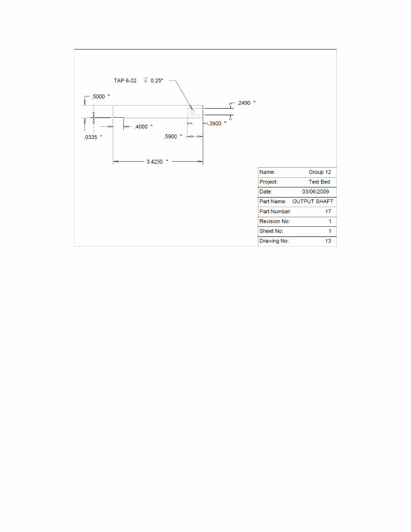
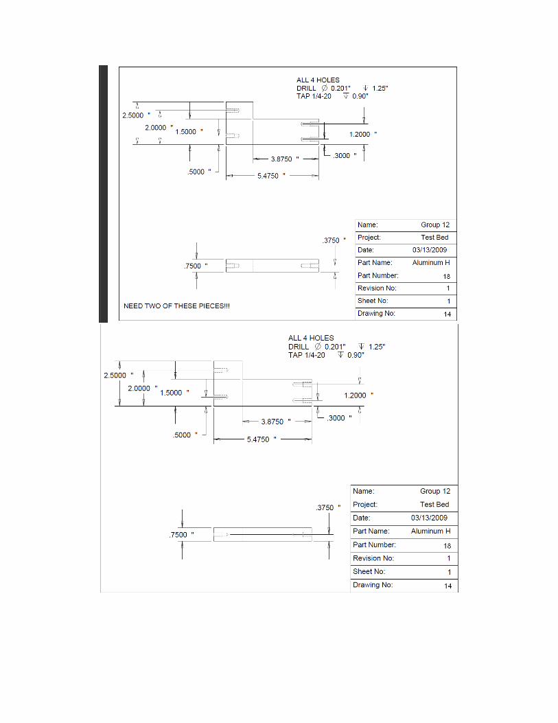
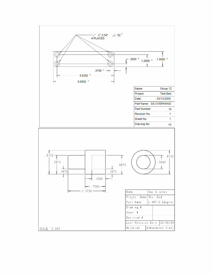
Appendix III
CAD Drawings