Embed Size (px)
Citation preview
GHD | 455 Phillip Street Unit #100A Waterloo Ontario N2L 3X2 Canada | 11201621 | Report No 2 | March 6 2020
Emission Summary and Dispersion Modelling Report
In support of:
2020 Environmental Compliance Approval Application Prepared for: Triple M Metal LP 799 Parkdale Avenue North Hamilton, Ontario
Page 1 of 2Disponible en français5357E (2017/03) © Queen's Printer for Ontario, 2017 PIBS 5357E
Ministry of the Environment and Climate Change
Emission Summary and Dispersion Modelling Report Checklist
Company Name
Triple M Metal Corp.Company AddressUnit Number101
Street Number 1
Street Name Kenview Blvd
PO Box
City/Town Brampton
Province Ontario
Postal Code L6T 5E6
Location of Facility799 Parkdale Avenue North, Hamilton, ON, L8H 7N5The attached Emission Summary and Dispersion Modeling Report was prepared in accordance with s. 26 of O. Reg. 419/05 and the guidance in the MOE document “Procedure for Preparing an Emission Summary and Dispersion Modelling Report” dated March 2009 and “Air Dispersion Modelling Guideline for Ontario” dated March 2009 and the minimum required information identified in the check-list on the reverse of this sheet has been submitted.
Company ContactCompany Contact
Company Contact NameLast Name Fancy
First Name Mike
Middle Initial
TitleQES Coordinator
Telephone Number 905 545-7083
Signature Date (yyyy/mm/dd)
2020/02/28
Technical ContactTechnical Contact
Technical Contact NameLast Name Martinez
First Name Erik
Middle Initial
RepresentingGHD Limted
Telephone Number 519 340-4213
Signature Date (yyyy/mm/dd)
2020/02/28
* This checklist is taken from the document titled "Procedure for Preparing an Emission Summary and Dispersion Modelling Report" dated March 2009.
Page 2 of 25357E (2017/03)
Emission Summary and Dispersion Modelling Report Checklist
Required Information Submitted Explanation/Reference
Executive Summary and Emission Summary Table Executive Summary and Emission Summary Table Executive Summary and Emission Summary Table Executive Summary and Emission Summary Table
1.1 Overview of ESDM Report 1.1 Overview of ESDM Report Yes✔ Executive Summary1.2 Emission Summary Table 1.2 Emission Summary Table Yes✔ Table 4
1.0 Introduction and Facility Description Introduction and Facility Description Introduction and Facility Description
1.1 Purpose and Scope of ESDM Report (when report only represents a portion of facility)
1.1 Purpose and Scope of ESDM Report (when report only represents a portion of facility) Yes✔ Section 1.1
1.2 Description of Processes and NAICS code(s) 1.2 Description of Processes and NAICS code(s) Yes✔ Section 1.21.3 Description of Products and Raw Materials 1.3 Description of Products and Raw Materials Yes✔ Section 1.31.4 Process Flow Diagram 1.4 Process Flow Diagram Yes✔ Section 1.4, Figure 41.5 Operating Schedule 1.5 Operating Schedule Yes✔ Section 1.5
2.0 Initial Identification of Sources and Contaminants Initial Identification of Sources and Contaminants Initial Identification of Sources and Contaminants
2.1 Sources and Contaminants Identification Table 2.1 Sources and Contaminants Identification Table Yes✔ Section 2.13.0 Assessment of the Significance of Contaminants and Sources Assessment of the Significance of Contaminants and Sources Assessment of the Significance of Contaminants and Sources
3.1 Identification of Negligible Contaminants and Sources 3.1 Identification of Negligible Contaminants and Sources Yes✔ Section 3.13.2 Rationale for Assessment 3.2 Rationale for Assessment Yes✔ Section 3.2, Appendix B
4.0 Operating Conditions, Emission Rate Estimating and Data Quality Operating Conditions, Emission Rate Estimating and Data Quality Operating Conditions, Emission Rate Estimating and Data Quality
4.1 Description of operating conditions, for each significant contaminant that results in the maximum POI concentration for that contaminant
4.1 Description of operating conditions, for each significant contaminant that results in the maximum POI concentration for that contaminant Yes✔ Section 4.1
4.2 Explanation of Method used to calculate the emission rate for each contaminant
4.2 Explanation of Method used to calculate the emission rate for each contaminant Yes✔ Section 4.2, Appendix A
4.3 Sample calculation for each method 4.3 Sample calculation for each method Yes✔ Section 4.3, Appendix A4.4 Assessment of Data Quality for each emission rate 4.4 Assessment of Data Quality for each emission rate Yes✔ Section 4.3, Table 2
5.0 Source Summary Table and Property Plan Source Summary Table and Property Plan Source Summary Table and Property Plan
5.1 Source Summary Table 5.1 Source Summary Table Yes✔ Section 5.1, Table 15.2 Site Plan (scalable) 5.2 Site Plan (scalable) Yes✔ Section 5.2, Figure 1
6.0 Dispersion Modelling Dispersion Modelling Dispersion Modelling
6.1 Dispersion Modelling Input Summary Table 6.1 Dispersion Modelling Input Summary Table Yes✔ Section 6.16.2 Land Use Zoning Designation Plan 6.2 Land Use Zoning Designation Plan Yes✔ Section 6.2, Figure 26.3 Dispersion Modelling Input and Output Files 6.3 Dispersion Modelling Input and Output Files Yes✔ Section 6.3
7.0 Emission Summary Table and Conclusions Emission Summary Table and Conclusions Emission Summary Table and Conclusions
7.1 Emission Summary Table 7.1 Emission Summary Table Yes✔ Table 47.2 Assessment of Contaminants with no MOE POI Limits 7.2 Assessment of Contaminants with no MOE POI Limits Yes NA7.3 Conclusions 7.3 Conclusions Yes✔ Section 7.3Appendices (Provide supporting information or details such as…) Appendices (Provide supporting information or details such as…) Appendices (Provide supporting information or details such as…) Appendices (Provide supporting information or details such as…)
Appendix A Yes✔ Supporting Calculations
Appendix B Yes✔Supporting Information for Assessment of Negligibility
Appendix D Yes✔ Electronic Modeling Files
Draft Document – For Discussion Only – Final Version May Differ From Draft
GHD | Emission Summary and Dispersion Modelling Report | 11201621 (2) | Page i
Version Control
Revision Date Revised Description Reviewer Initials 1.0 March 2020 ESDM Report was prepared to
support ECA (Air & Noise) Amendment Application
EM
Draft Document – For Discussion Only – Final Version May Differ From Draft
GHD | Emission Summary and Dispersion Modelling Report | 11201621 (2) | Page ii
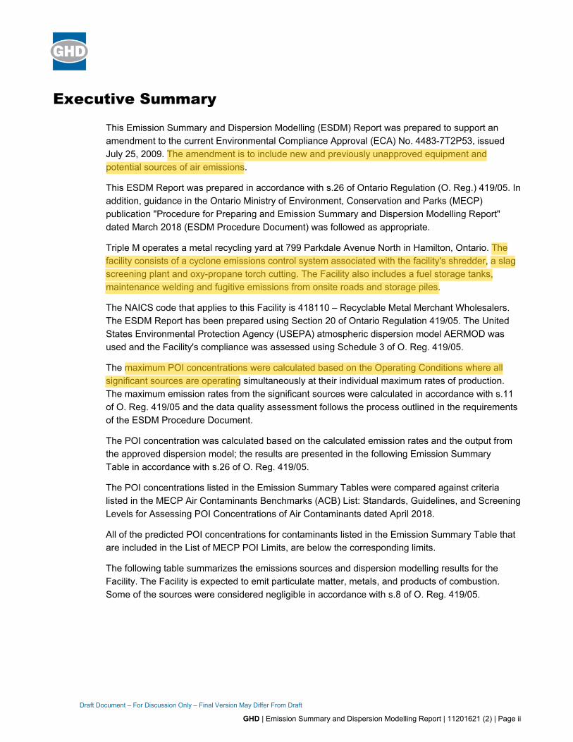
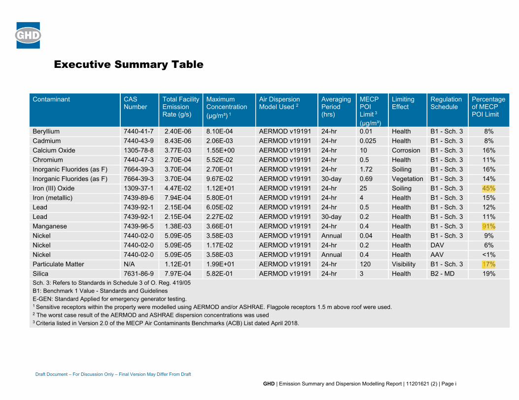
Executive Summary
This Emission Summary and Dispersion Modelling (ESDM) Report was prepared to support an amendment to the current Environmental Compliance Approval (ECA) No. 4483-7T2P53, issued July 25, 2009. The amendment is to include new and previously unapproved equipment and potential sources of air emissions.
This ESDM Report was prepared in accordance with s.26 of Ontario Regulation (O. Reg.) 419/05. In addition, guidance in the Ontario Ministry of Environment, Conservation and Parks (MECP) publication "Procedure for Preparing and Emission Summary and Dispersion Modelling Report" dated March 2018 (ESDM Procedure Document) was followed as appropriate.
Triple M operates a metal recycling yard at 799 Parkdale Avenue North in Hamilton, Ontario. The facility consists of a cyclone emissions control system associated with the facility's shredder, a slag screening plant and oxy-propane torch cutting. The Facility also includes a fuel storage tanks, maintenance welding and fugitive emissions from onsite roads and storage piles.
The NAICS code that applies to this Facility is 418110 – Recyclable Metal Merchant Wholesalers. The ESDM Report has been prepared using Section 20 of Ontario Regulation 419/05. The United States Environmental Protection Agency (USEPA) atmospheric dispersion model AERMOD was used and the Facility's compliance was assessed using Schedule 3 of O. Reg. 419/05.
The maximum POI concentrations were calculated based on the Operating Conditions where all significant sources are operating simultaneously at their individual maximum rates of production. The maximum emission rates from the significant sources were calculated in accordance with s.11 of O. Reg. 419/05 and the data quality assessment follows the process outlined in the requirements of the ESDM Procedure Document.
The POI concentration was calculated based on the calculated emission rates and the output from the approved dispersion model; the results are presented in the following Emission Summary Table in accordance with s.26 of O. Reg. 419/05.
The POI concentrations listed in the Emission Summary Tables were compared against criteria listed in the MECP Air Contaminants Benchmarks (ACB) List: Standards, Guidelines, and Screening Levels for Assessing POI Concentrations of Air Contaminants dated April 2018.
All of the predicted POI concentrations for contaminants listed in the Emission Summary Table that are included in the List of MECP POI Limits, are below the corresponding limits.
The following table summarizes the emissions sources and dispersion modelling results for the Facility. The Facility is expected to emit particulate matter, metals, and products of combustion. Some of the sources were considered negligible in accordance with s.8 of O. Reg. 419/05.
Draft Document – For Discussion Only – Final Version May Differ From Draft
GHD | Emission Summary and Dispersion Modelling Report | 11201621 (2) | Page i
Executive Summary Table
Contaminant CAS Number
Total Facility Emission Rate (g/s)
Maximum Concentration (μg/m³) 1
Air Dispersion Model Used 2
Averaging Period (hrs)
MECP POI Limit 3
(μg/m³)
Limiting Effect
Regulation Schedule
Percentage of MECP POI Limit
Beryllium 7440-41-7 2.40E-06 8.10E-04 AERMOD v19191 24-hr 0.01 Health B1 - Sch. 3 8% Cadmium 7440-43-9 8.43E-06 2.06E-03 AERMOD v19191 24-hr 0.025 Health B1 - Sch. 3 8% Calcium Oxide 1305-78-8 3.77E-03 1.55E+00 AERMOD v19191 24-hr 10 Corrosion B1 - Sch. 3 16% Chromium 7440-47-3 2.70E-04 5.52E-02 AERMOD v19191 24-hr 0.5 Health B1 - Sch. 3 11% Inorganic Fluorides (as F) 7664-39-3 3.70E-04 2.70E-01 AERMOD v19191 24-hr 1.72 Soiling B1 - Sch. 3 16% Inorganic Fluorides (as F) 7664-39-3 3.70E-04 9.67E-02 AERMOD v19191 30-day 0.69 Vegetation B1 - Sch. 3 14% Iron (III) Oxide 1309-37-1 4.47E-02 1.12E+01 AERMOD v19191 24-hr 25 Soiling B1 - Sch. 3 45% Iron (metallic) 7439-89-6 7.94E-04 5.80E-01 AERMOD v19191 24-hr 4 Health B1 - Sch. 3 15% Lead 7439-92-1 2.15E-04 6.05E-02 AERMOD v19191 24-hr 0.5 Health B1 - Sch. 3 12% Lead 7439-92-1 2.15E-04 2.27E-02 AERMOD v19191 30-day 0.2 Health B1 - Sch. 3 11% Manganese 7439-96-5 1.38E-03 3.66E-01 AERMOD v19191 24-hr 0.4 Health B1 - Sch. 3 91% Nickel 7440-02-0 5.09E-05 3.58E-03 AERMOD v19191 Annual 0.04 Health B1 - Sch. 3 9% Nickel 7440-02-0 5.09E-05 1.17E-02 AERMOD v19191 24-hr 0.2 Health DAV 6% Nickel 7440-02-0 5.09E-05 3.58E-03 AERMOD v19191 Annual 0.4 Health AAV <1% Particulate Matter N/A 1.12E-01 1.99E+01 AERMOD v19191 24-hr 120 Visibility B1 - Sch. 3 17% Silica 7631-86-9 7.97E-04 5.82E-01 AERMOD v19191 24-hr 3 Health B2 - MD 19% Sch. 3: Refers to Standards in Schedule 3 of O. Reg. 419/05 B1: Benchmark 1 Value - Standards and Guidelines E-GEN: Standard Applied for emergency generator testing. 1 Sensitive receptors within the property were modelled using AERMOD and/or ASHRAE. Flagpole receptors 1.5 m above roof were used. 2 The worst case result of the AERMOD and ASHRAE dispersion concentrations was used 3 Criteria listed in Version 2.0 of the MECP Air Contaminants Benchmarks (ACB) List dated April 2018.
GHD | Emission Summary and Dispersion Modelling Report | 11201621 (2) | Page i
Table of Contents
1. Introduction and Facility Description ............................................................................................ 1
1.1 Purpose and Scope of ESDM Report ................................................................................ 1
1.2 Description of Processes and NAICS Codes..................................................................... 1
1.2.1 Shredding ......................................................................................................... 1 1.2.2 Slag Metal Recovery ........................................................................................ 3 1.2.3 Oxy-Propane Metal Cutting .............................................................................. 4 1.2.4 Repair Welding ................................................................................................. 4 1.2.5 Comfort Heating ................................................................................................ 4
1.3 Description of Products and Raw Materials ....................................................................... 4
1.4 Process Flow Diagram ....................................................................................................... 4
1.5 Operating Schedule ........................................................................................................... 4
1.6 Facility Production Limit ..................................................................................................... 4
2. Initial Identification of Sources and Contaminants ....................................................................... 4
2.1 Sources and Contaminants Identification Table ................................................................ 5
3. Assessment of Significance of Sources and Contaminants......................................................... 5
3.1 Identification of Negligible Contaminants and Sources ..................................................... 5
3.2 Rationale for Assessment .................................................................................................. 5
4. Operating Conditions, Emissions Estimating and Data Quality ................................................... 5
4.1 Description of Operating Conditions .................................................................................. 6
4.2 Explanation of The Methods Used to Calculate Emission Rates ...................................... 6
4.3 Sample Calculations .......................................................................................................... 6
4.4 Assessment of Data Quality .............................................................................................. 6
5. Source Summary Table and Site Plan ......................................................................................... 7
5.1 Source Summary Table ..................................................................................................... 7
5.2 Site Plan ............................................................................................................................. 7
6. Dispersion Modelling .................................................................................................................... 8
6.1 Dispersion Modelling Input Summary Table ...................................................................... 8
6.2 Coordinate System ............................................................................................................ 9
6.3 Meteorology and Land Use Zoning Plan ........................................................................... 9
6.4 Terrain ................................................................................................................................ 9
6.5 Receptors ........................................................................................................................... 9
6.6 Building Downwash .......................................................................................................... 10
6.7 Deposition ........................................................................................................................ 10
GHD | Emission Summary and Dispersion Modelling Report | 11201621 (2) | Page ii
Table of Contents 6.8 Averaging Time and Conversions .................................................................................... 10
6.9 Dispersion Modelling Options .......................................................................................... 10
6.10 Dispersion Modelling Input and Output Files ................................................................... 11
7. Emission Summary Table and Conclusions .............................................................................. 11
7.1 Emission Summary Table ................................................................................................ 11
7.2 Assessment of Contaminants with no MECP POI Limits ................................................ 12
7.3 Conclusions ..................................................................................................................... 12
Figure Index Figure 1 Site Location Plan
Figure 2 Land Use Zoning Designation Plan
Figure 3 Source Plan and Roof Layout
Figure 4 Process Flow Diagram – Shredding Plant
Figure 5 Process Flow Diagram – Slag Screening Plant
Table Index Table 1 Source and Contaminant Identification Table
Table 2 Source Summary Table
Table 3 Dispersion Modelling Input Summary Table
Table 4 Emission Summary Table
Appendix Index Appendix A Supporting Calculations
Appendix B Supporting Information for Assessment of Negligibility
Appendix C Environmental Compliance Approval No. 4483-7T2P53
Appendix D Dispersion Modelling Files (Electronic)
Appendix E Shredder June 2005 Source Test Report
Appendix F Oxy-Propane January 2011 Source Test Report
Appendix G Safety Data Sheets for Welding
GHD | Emission Summary and Dispersion Modelling Report | 11201621 (2) | Page 1
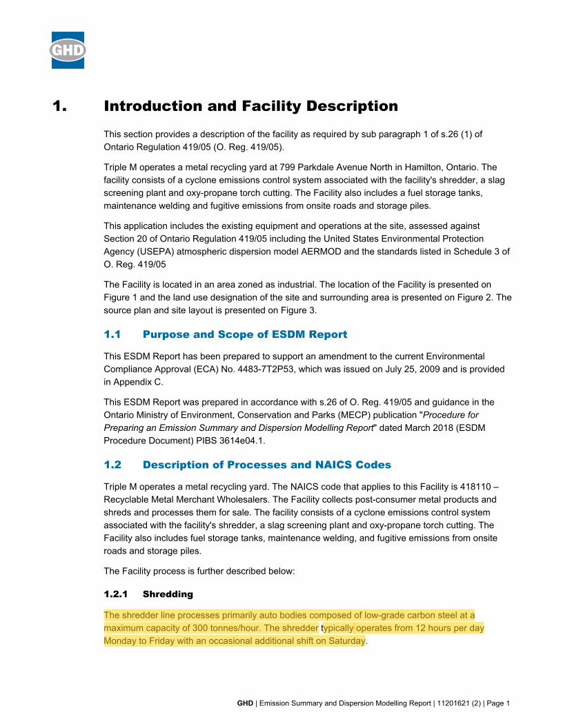
1. Introduction and Facility Description
This section provides a description of the facility as required by sub paragraph 1 of s.26 (1) of Ontario Regulation 419/05 (O. Reg. 419/05).
Triple M operates a metal recycling yard at 799 Parkdale Avenue North in Hamilton, Ontario. The facility consists of a cyclone emissions control system associated with the facility's shredder, a slag screening plant and oxy-propane torch cutting. The Facility also includes a fuel storage tanks, maintenance welding and fugitive emissions from onsite roads and storage piles.
This application includes the existing equipment and operations at the site, assessed against Section 20 of Ontario Regulation 419/05 including the United States Environmental Protection Agency (USEPA) atmospheric dispersion model AERMOD and the standards listed in Schedule 3 of O. Reg. 419/05
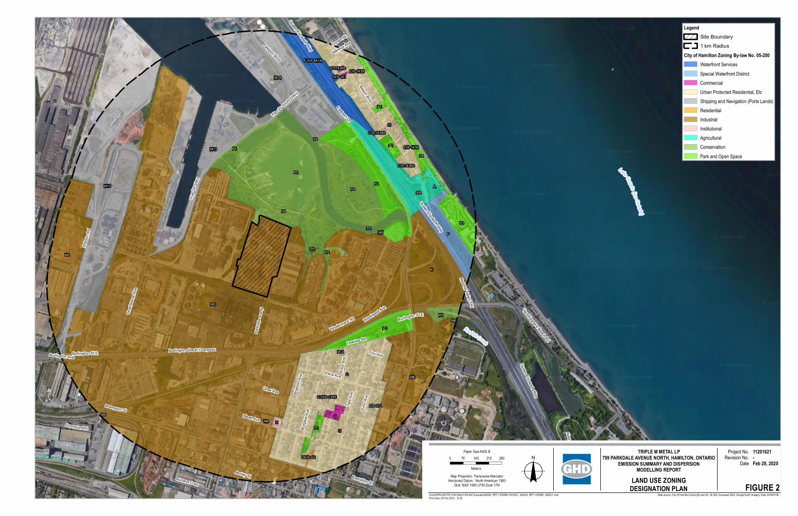
The Facility is located in an area zoned as industrial. The location of the Facility is presented on Figure 1 and the land use designation of the site and surrounding area is presented on Figure 2. The source plan and site layout is presented on Figure 3.
1.1 Purpose and Scope of ESDM Report
This ESDM Report has been prepared to support an amendment to the current Environmental Compliance Approval (ECA) No. 4483-7T2P53, which was issued on July 25, 2009 and is provided in Appendix C.
This ESDM Report was prepared in accordance with s.26 of O. Reg. 419/05 and guidance in the Ontario Ministry of Environment, Conservation and Parks (MECP) publication "Procedure for Preparing an Emission Summary and Dispersion Modelling Report" dated March 2018 (ESDM Procedure Document) PIBS 3614e04.1.
1.2 Description of Processes and NAICS Codes
Triple M operates a metal recycling yard. The NAICS code that applies to this Facility is 418110 – Recyclable Metal Merchant Wholesalers. The Facility collects post-consumer metal products and shreds and processes them for sale. The facility consists of a cyclone emissions control system associated with the facility's shredder, a slag screening plant and oxy-propane torch cutting. The Facility also includes fuel storage tanks, maintenance welding, and fugitive emissions from onsite roads and storage piles.
The Facility process is further described below:
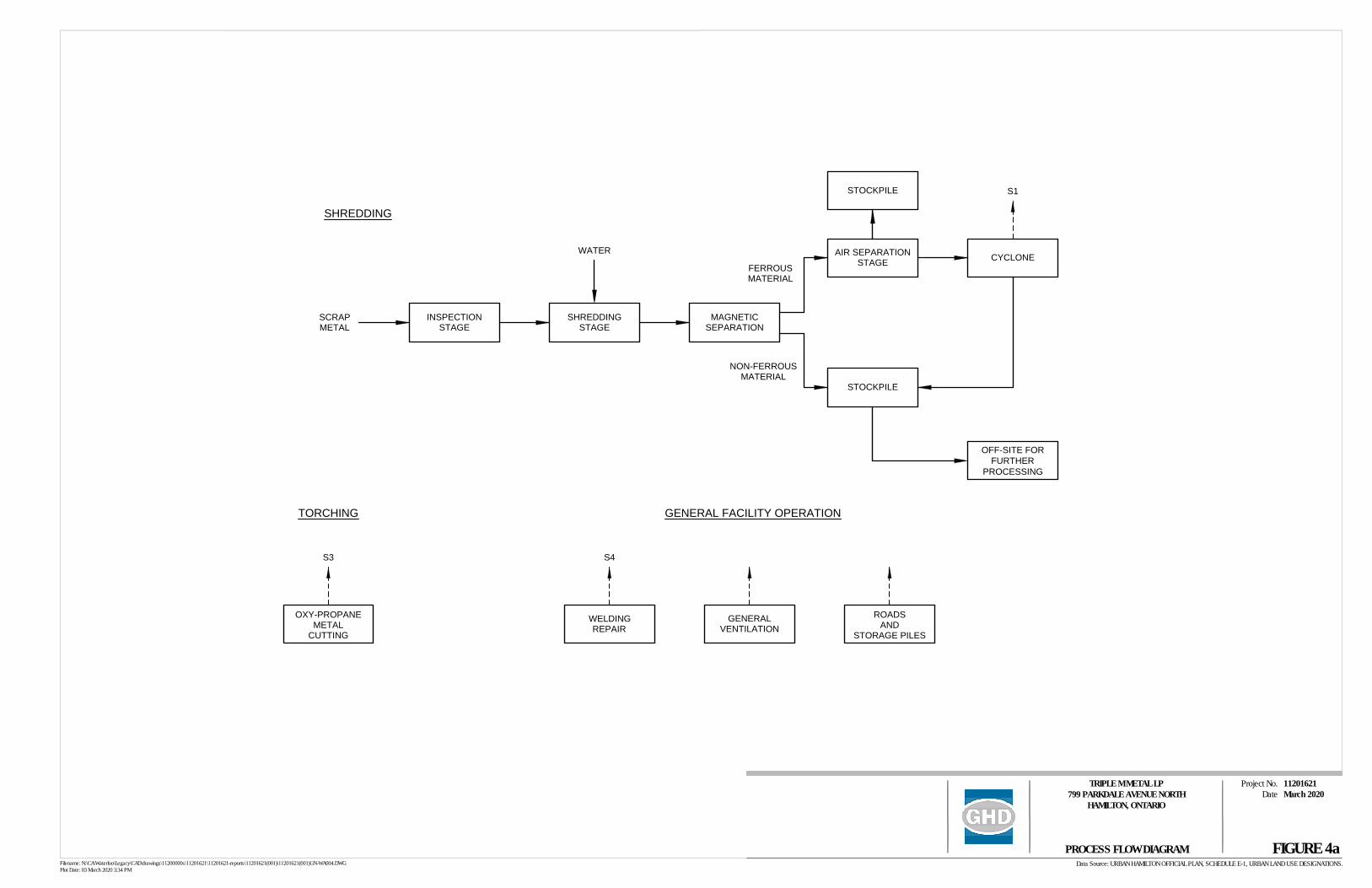
1.2.1 Shredding
The shredder line processes primarily auto bodies composed of low-grade carbon steel at a maximum capacity of 300 tonnes/hour. The shredder typically operates from 12 hours per day Monday to Friday with an occasional additional shift on Saturday.
GHD | Emission Summary and Dispersion Modelling Report | 11201621 (2) | Page 2
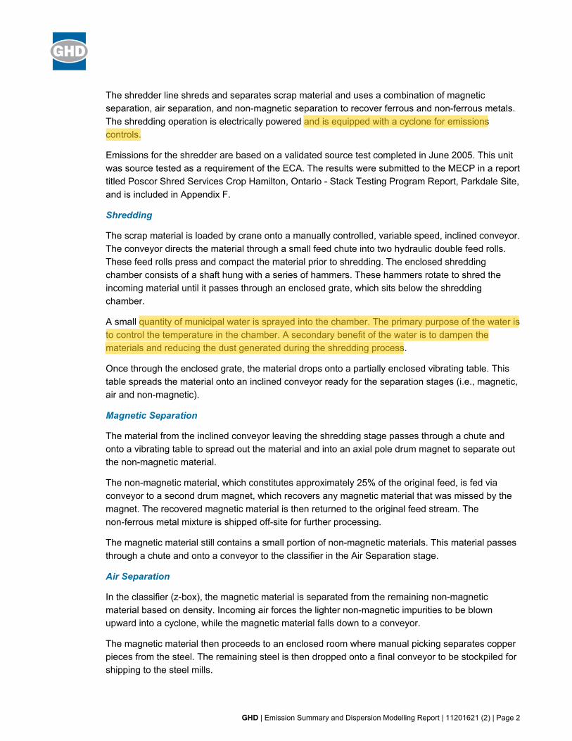
The shredder line shreds and separates scrap material and uses a combination of magnetic separation, air separation, and non-magnetic separation to recover ferrous and non-ferrous metals. The shredding operation is electrically powered and is equipped with a cyclone for emissions controls.
Emissions for the shredder are based on a validated source test completed in June 2005. This unit was source tested as a requirement of the ECA. The results were submitted to the MECP in a report titled Poscor Shred Services Crop Hamilton, Ontario - Stack Testing Program Report, Parkdale Site, and is included in Appendix F.
Shredding
The scrap material is loaded by crane onto a manually controlled, variable speed, inclined conveyor. The conveyor directs the material through a small feed chute into two hydraulic double feed rolls. These feed rolls press and compact the material prior to shredding. The enclosed shredding chamber consists of a shaft hung with a series of hammers. These hammers rotate to shred the incoming material until it passes through an enclosed grate, which sits below the shredding chamber.
A small quantity of municipal water is sprayed into the chamber. The primary purpose of the water is to control the temperature in the chamber. A secondary benefit of the water is to dampen the materials and reducing the dust generated during the shredding process.
Once through the enclosed grate, the material drops onto a partially enclosed vibrating table. This table spreads the material onto an inclined conveyor ready for the separation stages (i.e., magnetic, air and non-magnetic).
Magnetic Separation
The material from the inclined conveyor leaving the shredding stage passes through a chute and onto a vibrating table to spread out the material and into an axial pole drum magnet to separate out the non-magnetic material.
The non-magnetic material, which constitutes approximately 25% of the original feed, is fed via conveyor to a second drum magnet, which recovers any magnetic material that was missed by the magnet. The recovered magnetic material is then returned to the original feed stream. The non-ferrous metal mixture is shipped off-site for further processing.
The magnetic material still contains a small portion of non-magnetic materials. This material passes through a chute and onto a conveyor to the classifier in the Air Separation stage.
Air Separation
In the classifier (z-box), the magnetic material is separated from the remaining non-magnetic material based on density. Incoming air forces the lighter non-magnetic impurities to be blown upward into a cyclone, while the magnetic material falls down to a conveyor.
The magnetic material then proceeds to an enclosed room where manual picking separates copper pieces from the steel. The remaining steel is then dropped onto a final conveyor to be stockpiled for shipping to the steel mills.
GHD | Emission Summary and Dispersion Modelling Report | 11201621 (2) | Page 3
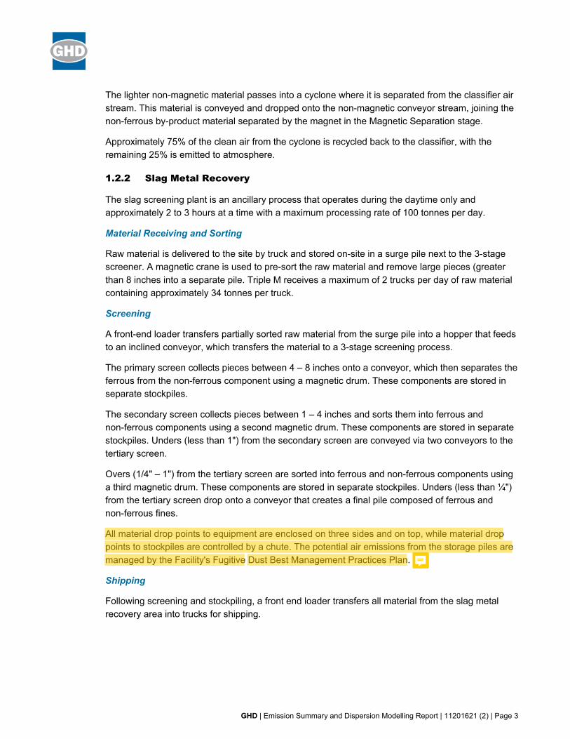
The lighter non-magnetic material passes into a cyclone where it is separated from the classifier air stream. This material is conveyed and dropped onto the non-magnetic conveyor stream, joining the non-ferrous by-product material separated by the magnet in the Magnetic Separation stage.
Approximately 75% of the clean air from the cyclone is recycled back to the classifier, with the remaining 25% is emitted to atmosphere.
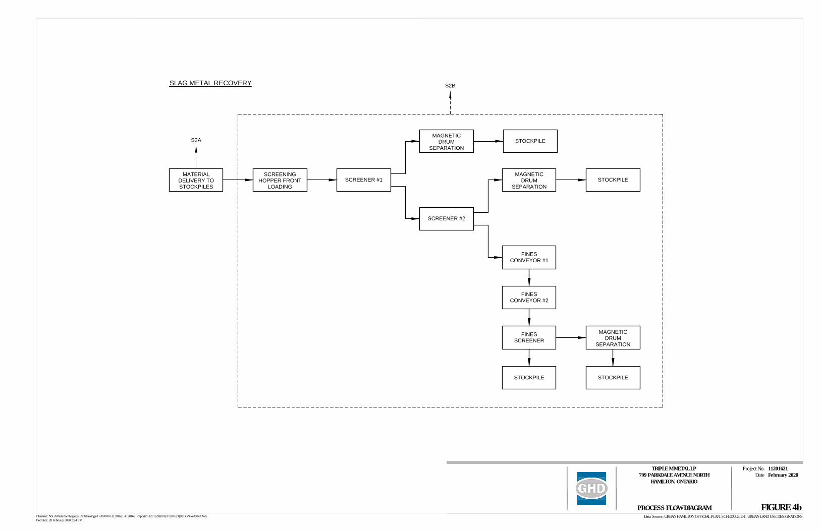
1.2.2 Slag Metal Recovery
The slag screening plant is an ancillary process that operates during the daytime only and approximately 2 to 3 hours at a time with a maximum processing rate of 100 tonnes per day.
Material Receiving and Sorting
Raw material is delivered to the site by truck and stored on-site in a surge pile next to the 3-stage screener. A magnetic crane is used to pre-sort the raw material and remove large pieces (greater than 8 inches into a separate pile. Triple M receives a maximum of 2 trucks per day of raw material containing approximately 34 tonnes per truck.
Screening
A front-end loader transfers partially sorted raw material from the surge pile into a hopper that feeds to an inclined conveyor, which transfers the material to a 3-stage screening process.
The primary screen collects pieces between 4 – 8 inches onto a conveyor, which then separates the ferrous from the non-ferrous component using a magnetic drum. These components are stored in separate stockpiles.
The secondary screen collects pieces between 1 – 4 inches and sorts them into ferrous and non-ferrous components using a second magnetic drum. These components are stored in separate stockpiles. Unders (less than 1") from the secondary screen are conveyed via two conveyors to the tertiary screen.
Overs (1/4" – 1") from the tertiary screen are sorted into ferrous and non-ferrous components using a third magnetic drum. These components are stored in separate stockpiles. Unders (less than ¼") from the tertiary screen drop onto a conveyor that creates a final pile composed of ferrous and non-ferrous fines.
All material drop points to equipment are enclosed on three sides and on top, while material drop points to stockpiles are controlled by a chute. The potential air emissions from the storage piles are managed by the Facility's Fugitive Dust Best Management Practices Plan.
Shipping
Following screening and stockpiling, a front end loader transfers all material from the slag metal recovery area into trucks for shipping.
GHD | Emission Summary and Dispersion Modelling Report | 11201621 (2) | Page 4
1.2.3 Oxy-Propane Metal Cutting
Oxy-propane metal cutting involves the cutting of various billets of steel with hand-held oxy-propane torches. The steel billets are heated by the torch flame, forming a solid slag residue along the cutting edge. Metal cutting activities take place along the northern portion of the site, as shown in Figure 3.
1.2.4 Repair Welding
Repair welding is performed on an as required basis within the shredder line area in the maintenance building. Typical electrodes E7018 and E6013 used in the shielded metal arc welding (SMAW) are consumed.
1.2.5 Comfort Heating
Comfort heating in the office and maintenance building is electrically powered. Therefore, there are no emissions from comfort heating.
1.3 Description of Products and Raw Materials
The facility receives shipments of post consumer scrap metals (including vehicle and non-vehicle sources), shreds and separates waste materials from multiple sources. Materials are sorted according to type, and sold to manufacturers.
Product usages and process information are provided in greater detail in Appendix A. Refer to Table 1, which tabulates the individual sources of emissions at the Facility.
1.4 Process Flow Diagram
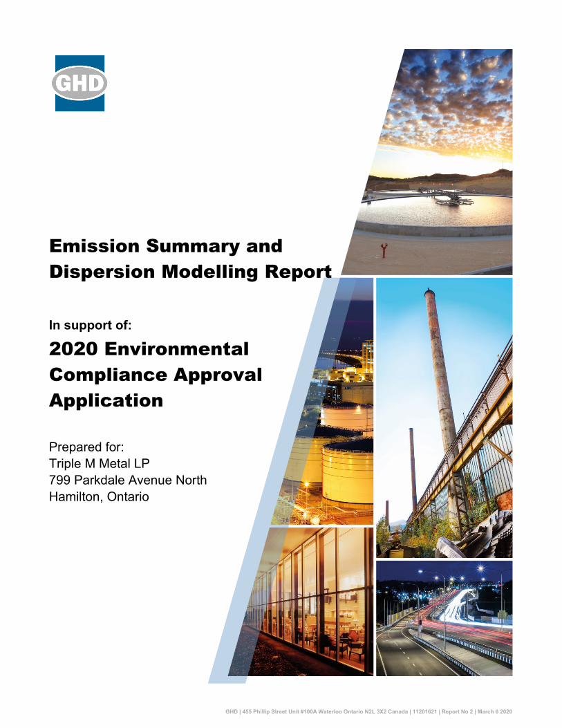
Refer to Figure 4 for a graphical representation of the Facility processes.
1.5 Operating Schedule
The Facility operates from 7 a.m. to 11 p.m., Monday through Friday, all year round. The facility may, on occasion, work longer hours or operate on weekends.
1.6 Facility Production Limit
The Facility's maximum total material shredded is 860,000 tonnes per year.
The Facility's maximum slag screening rate is 36,500 tonnes per year.
2. Initial Identification of Sources and Contaminants
This section provides an initial identification of all of the sources and contaminants emitted at the Facility, as required by subparagraphs 2 to 4 of s.26 (1) of O. Reg. 419/05.
There may be general ventilation from the Facility that only discharges uncontaminated air from the workspaces or air from the workspace that may include contaminants that come from commercial
GHD | Emission Summary and Dispersion Modelling Report | 11201621 (2) | Page 5
office supplies, building maintenance products or supplies and activities; these types of ventilation sources are considered to be negligible and were not identified as sources at the Facility.
It should be noted that general ventilation located in the process area that does not vent process emissions is also considered negligible.
2.1 Sources and Contaminants Identification Table
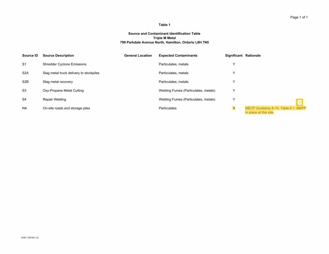
Table 1 tabulates all the emission sources at the Facility. Table 1 provides the information required for sub paragraphs 2 to 4 of s.26 (1) of O. Reg. 419/05.
The expected contaminants emitted from each source are also identified in Table 1. Each of the identified sources has been assigned a source reference number.
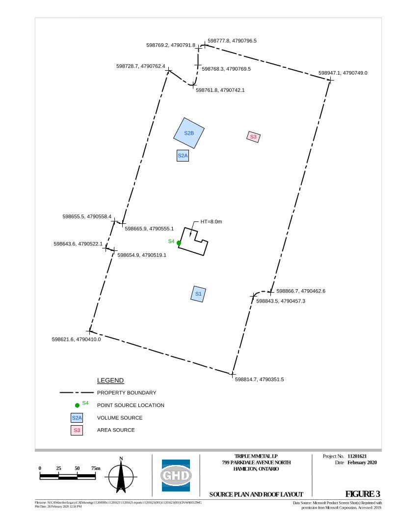
The location of the discharges from each of the sources is presented on Figure 3. The location of each of the sources is specified with the source reference number.
3. Assessment of Significance of Sources and Contaminants
This section provides an explanation for each source identified as negligible in Table 1, as required by subparagraph 5 of s.26(1) of O. Reg. 419/05.
In Accordance with s.8 of O. Reg. 419/05, emission rate calculations and dispersion modelling does not have to be performed for emissions from negligible sources or for the emission of negligible contaminants from significant sources.
3.1 Identification of Negligible Contaminants and Sources
Each negligible source is identified in Table 1 – Sources and Contaminants Identification Table. The remaining sources are significant. These sources will be included in the dispersion modelling for the site.
3.2 Rationale for Assessment
For each source or contaminant in Table 1 that has been identified as being negligible there is an accompanying documented rationale. The technical information required to substantiate the argument that each of the identified sources or contaminants is negligible is presented in Appendix C – Supporting Information for Assessment of Negligibility.
4. Operating Conditions, Emissions Estimating and Data Quality
This section provides a description of the operating conditions used in the calculation of the emission estimates and an assessment of the data quality of the emission estimates for each significant contaminant from the facility as required by sub paragraphs 6 and 7 of s.26 (1) of
GHD | Emission Summary and Dispersion Modelling Report | 11201621 (2) | Page 6
O. Reg. 419/05. In accordance with s.8 of O. Reg. 419/05, emission rate calculations and dispersion modelling does not have to be performed for emissions from negligible sources or for the emission of negligible contaminants from significant sources.
4.1 Description of Operating Conditions
Section 10 of O. Reg. 419/05 states that an acceptable operating condition is a scenario that assumes operating conditions for the Facility that would result, for the relevant contaminant, in the highest concentration of the contaminant at POI that the Facility is capable of, the operating condition described in this ESDM Report meets this requirement.
The averaging time for the operating condition is based on the applicable averaging times for each contaminant. The operating condition used for this Facility that results in the maximum concentration at a POI is the scenario where all significant sources are operating simultaneously at their individual maximum rates of production. The individual maximum rates of production for each significant source of emissions correspond to the maximum emission rate during the appropriate averaging time. The individual maximum rates of production for each significant source of emissions are explicitly described in Appendix B.
4.2 Explanation of The Methods Used to Calculate Emission Rates
The maximum emission rates for each significant contaminant emitted from the significant sources were calculated in accordance with requirements of the ESDM Procedure Document.
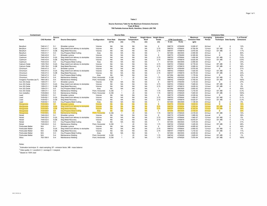
The emission rate for each significant contaminant emitted from a significant source was estimated and the methodology for the calculation is documented in Table 2.
4.3 Sample Calculations
The technical rationale, including sample calculations, required to substantiate the emission rates presented in Table 2, is documented in Appendix A.
4.4 Assessment of Data Quality
This section provides a description of the assessment of the data quality of the emission estimates for each significant contaminant from the facility.
The assessment of the data quality of the emission rate estimates for each significant contaminant emitted from the significant sources was performed in accordance with the requirements of sub paragraph 7iii of s.26 (1) of O. Reg. 419/05.
For each contaminant the emission rate was estimated and the data quality of the estimate is documented in Table 2. The assessment of data quality for each source listed in Table 2 is documented in Appendix A.
All emission rates listed in Table 2 are documented as having the highest available data quality and correspond to an operating scenario where all significant sources are operating simultaneously at their individual maximum rates of production. Therefore, emission rate estimates listed in Table 2
GHD | Emission Summary and Dispersion Modelling Report | 11201621 (2) | Page 7
are not likely to be an underestimate of the actual emission rates and use of these emission rates will result in an estimated concentration at POI greater than actual concentrations.
5. Source Summary Table and Site Plan
This section provides the table required by sub paragraph 8 and the site plan required by sub paragraph 9 of s.26 (1) of O. Reg. 419/05.
5.1 Source Summary Table
Emission rate estimates for each source of significant contaminants are documented in Table 2 in accordance with requirements of subparagraph 8 of s.26 (1) of O. Reg. 419/05.
For each source of significant contaminants the following parameters are referenced:
• Contaminant
• Chemical Abstract Service (CAS) reference number
• Source reference number
• Source description
• Stack parameters (flow rate, exhaust temperature, diameter, height above grade, height above roof)
• Location referenced to a Universal Transverse Mercator (UTM) coordinates system presented on Figure 2
• Maximum emission rate
• Averaging period
• Emission estimating technique
• Estimation data quality
• Percentage of overall emission
5.2 Site Plan
The locations of the emission sources listed in Table 2 are presented on Figure 3; the location of each of the sources is specified with the source reference number. The location of the property-line is indicated on Figure 3, with the end points of each section of the property-line clearly referenced in a UTM coordinate system. The location of each source is referenced to this coordinate system under a column in Table 2A and Table 2B.
The heights of the structures, if applicable, are labelled on Figure 3.
GHD | Emission Summary and Dispersion Modelling Report | 11201621 (2) | Page 8
6. Dispersion Modelling
This section provides a description of how the dispersion modelling was conducted at the Facility to calculate the maximum concentration at a POI.
The dispersion modelling was conducted in accordance with the ministry publication "Air Dispersion Modelling Guideline for Ontario" PIBS 5165e03 (The ADMGO). A general description of the input data used in the dispersion model is provided below and summarized in Table 3.
Since the Facility is subject to s.20 of O. Reg. 419/05, compliance has been assessed using the AERMOD dispersion model and the standards listed in Schedule 3 of O. Reg. 419/05. Air dispersion modelling was performed following the MECP document "Air Dispersion Modelling Guideline for Ontario, Version 3.0", PIBS 5165e03.
The AERMOD modelling system has been identified by the MECP as one of the approved dispersion models under O. Reg. 419/05, and currently includes the Plume Rise Model Enhancements (PRIME) algorithms for assessing the effects of buildings on air dispersion.
The AERMOD modelling system is made up of the AERMOD dispersion model, the AERMET meteorological pre-processor and the AERMAP terrain pre-processor. The following approved dispersion model and pre-processors were used in the assessment:
• AERMOD dispersion model (v. 19191)
• AERMAP surface pre-processor (v. 11103)
• BPIP building downwash pre-processor (v. 04274)
The Facility sources were modelled as point sources. A summary of the AERMOD source input parameters is provided in Appendix D.
AERMET was not used in this assessment, as a pre-processed MECP meteorological dataset was used.
The emission rates used in the dispersion model meet the requirements of Section 11(1) 1 of O. Reg. 419/05, which requires that the emission rate used in the dispersion model is at least as high as the maximum emission rate that the source of contaminant is reasonably capable of for the relevant contaminant. These emission rates are further described in Appendix B.
There is no child care facility, health care facility, senior's residence, long-term care facility, or an education facility located at the Facility. Furthermore, the nearest POI is located greater than 5 metres from the building on which the point of emissions are located. As such, same structure contamination was not considered.
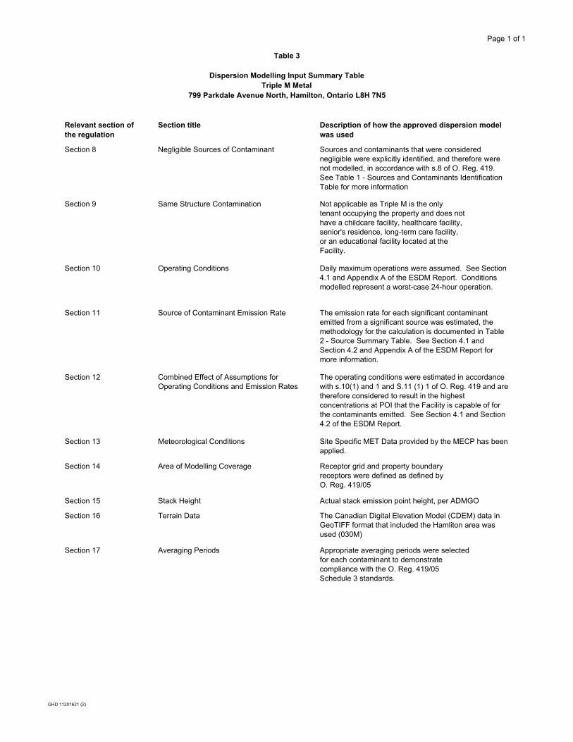
6.1 Dispersion Modelling Input Summary Table
A description of how the approved dispersion model was performed is included in Table 3. This table meets both the requirements of s.26 (1) 11 and sections 8-17 of O. Reg. 419/05 and follows the format provided in the ESDM Procedure Document.
GHD | Emission Summary and Dispersion Modelling Report | 11201621 (2) | Page 9
6.2 Coordinate System
The Universal Transverse Mercator (UTM) coordinate system, as per Section 5.2.2 of the ADMGO, was used to specify model object sources, buildings and receptors. All coordinates were defined in the North American Datum of 1983 (NAD83).
All sources and buildings are provided on Figure 3 and the property line coordinates are provided on Figure 3.
6.3 Meteorology and Land Use Zoning Plan
Triple M is located near a large body of water, approximately 1 km from Lake Ontario and is therefore required to use a site-specific meteorological dataset. The MECP issued approval under O. Reg. 419/05 Paragraph 3 of section 13(1) along with the pre-processed site-specific meteorological data set (2014 – 2018) using upper air data from the US National Weather Service's Buffalo station and surface data from the Environment and Climate Change Canada's (ECCC's) Burlington Piers station with cloud cover data from the Hamilton airport station.
A land use zoning plan is provided on Figure 2, which illustrates the extents of the Site property boundary and provides the zoning of adjacent land uses. The Site is located in a General Industrial zoned area that is surrounded by industrial and park zones. The nearest residential zoned land is located approximately 420 m southeast of the Facility, on Brighton Ave.
6.4 Terrain
AERMOD captures the essential physics of dispersion in complex terrain though the use of a separate height scale factor for each receptor (USEPA, 1998 – AERMAP UG). The highest scale factor represents the terrain that would dominate flow in the vicinity of the receptor.
The height scale factor that is used by AERMOD is generated by a AERMAP terrain pre-processor. AERMAP utilizes terrain data, or Digital Elevation Model (DEM) data in conjunction with a layout of receptors and sources to height scale factors that can be directly used in AERMOD. Terrain data used in this assessment was obtained from MECP (7.5-minute format).
6.5 Receptors
Receptors were chosen based on recommendations provided in Section 7.1 of the ADMGO, which is in accordance with s.14 of O. Reg. 419/05. A tiered receptor grid was defined starting with a rectangular boundary that encloses all the modelled sources (bounding box). A tiered grid was then defined starting from the edge of the bounding box with a fine resolution, to coarser resolutions further away. All tiered distances were defined relative to the bounding box. The receptor grid used is described as follows:
• 20-m spacing within 200 m of the edge of the bounding box
• 50-m spacing from 200 to 500 m
• 100-m spacing from 500 to 1,000 m
• 200-m spacing from 1,000 to 2,000 m
GHD | Emission Summary and Dispersion Modelling Report | 11201621 (2) | Page 10
• 500-m spacing from 2,000 to 5,000 m
A property line ground level receptor grid with 10-m spacing was used to evaluate the maximum property boundary concentration. No receptors were placed inside the Site's property line.
6.6 Building Downwash
The Facility buildings were entered into the model using the USEPA Building Profile Input Program (BPIP-PRIME). The inputs into this pre-processor include the co-ordinates and heights of the buildings and stacks. The BPIP program was executed to evaluate any building cavity downwash effects. Cavity downwash can result in air contaminants being forced to ground level prematurely under certain meteorological conditions. The on-site buildings and structures were modelled with their respective average roof heights.
The PRIME plume rise algorithms include vertical wind shear calculations (important for buoyant releases from short stacks (i.e., stacks at release heights within the recirculation zones of the buildings). The PRIME algorithm also allows for the wind speed deficit factors to improve the accuracy of predicted concentrations within building wake zones that form in the lee of buildings. The BPIP input file is provided in Appendix D.
6.7 Deposition
AERMOD has the ability to account for wet and dry deposition of substances that would reduce ground level concentrations at POIs. However, the deposition algorithm has not been implemented in this assessment and therefore, the predicted POI concentrations are considered to be more conservative.
6.8 Averaging Time and Conversions
The shortest time scale that AERMOD predicts is a 1-hour average value. Schedule 3 standards of O. Reg. 419/05 apply to this Facility; many of these standards are based on 1-hour and 24-hour averaging times, which are averaging times that are easily provided by AERMOD. In cases where a standard has an averaging period less than 1-hour (e.g., 10-minute), a conversion to the appropriate averaging period was completed using the MECP recommended conversion factors, as documented in the ADMGO.
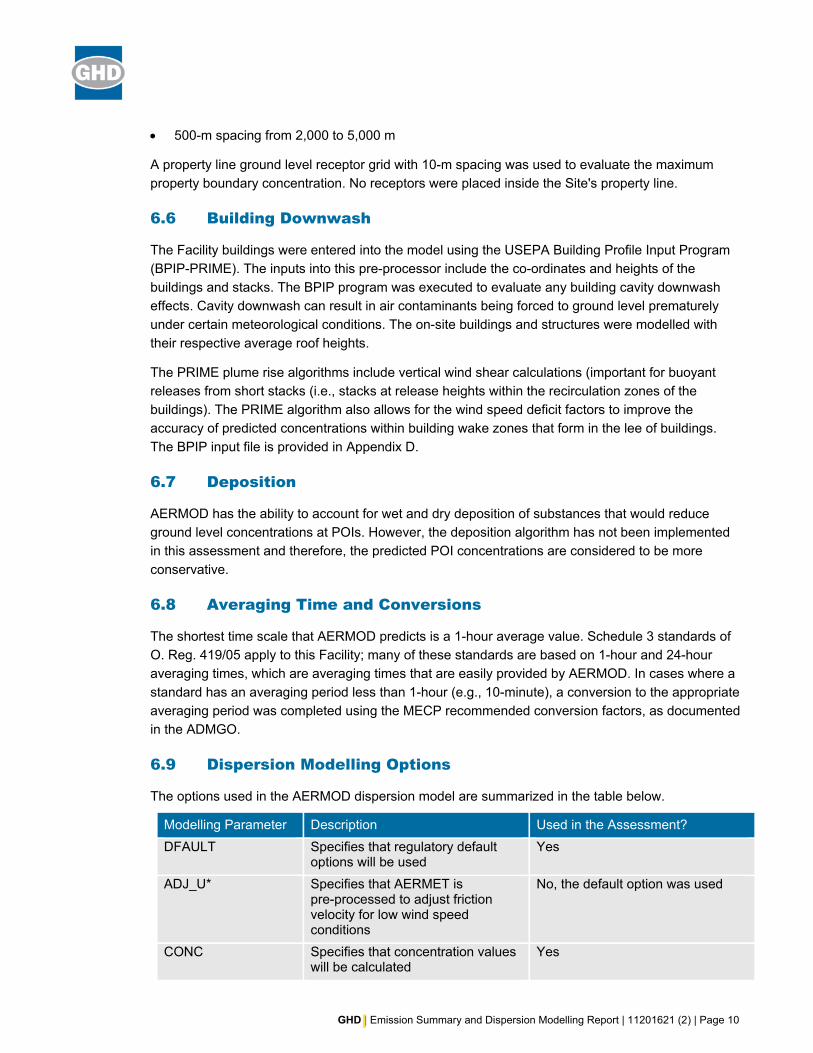
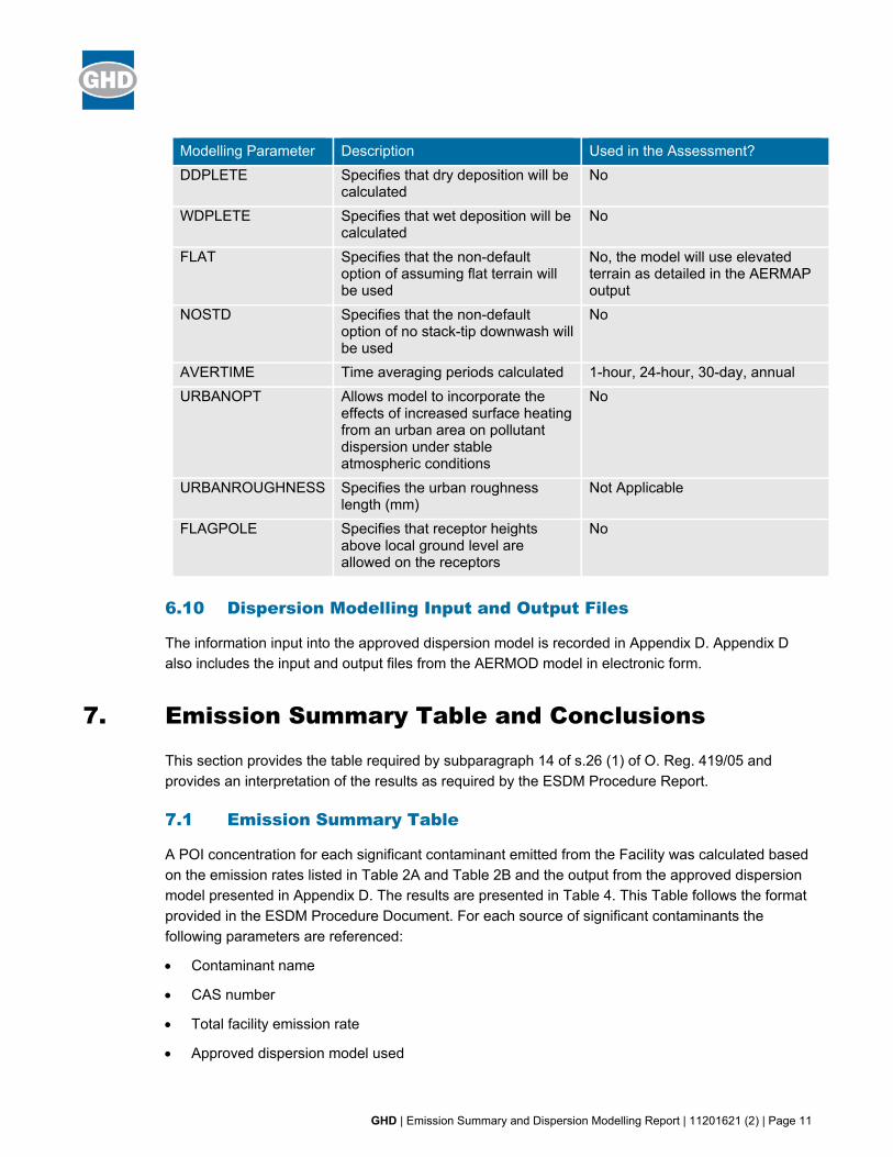
6.9 Dispersion Modelling Options
The options used in the AERMOD dispersion model are summarized in the table below.
Modelling Parameter Description Used in the Assessment? DFAULT Specifies that regulatory default
options will be used Yes
ADJ_U* Specifies that AERMET is pre-processed to adjust friction velocity for low wind speed conditions
No, the default option was used
CONC Specifies that concentration values will be calculated
Yes
GHD | Emission Summary and Dispersion Modelling Report | 11201621 (2) | Page 11
Modelling Parameter Description Used in the Assessment? DDPLETE Specifies that dry deposition will be
calculated No
WDPLETE Specifies that wet deposition will be calculated
No
FLAT Specifies that the non-default option of assuming flat terrain will be used
No, the model will use elevated terrain as detailed in the AERMAP output
NOSTD Specifies that the non-default option of no stack-tip downwash will be used
No
AVERTIME Time averaging periods calculated 1-hour, 24-hour, 30-day, annual URBANOPT Allows model to incorporate the
effects of increased surface heating from an urban area on pollutant dispersion under stable atmospheric conditions
No
URBANROUGHNESS Specifies the urban roughness length (mm)
Not Applicable
FLAGPOLE Specifies that receptor heights above local ground level are allowed on the receptors
No
6.10 Dispersion Modelling Input and Output Files
The information input into the approved dispersion model is recorded in Appendix D. Appendix D also includes the input and output files from the AERMOD model in electronic form.
7. Emission Summary Table and Conclusions
This section provides the table required by subparagraph 14 of s.26 (1) of O. Reg. 419/05 and provides an interpretation of the results as required by the ESDM Procedure Report.
7.1 Emission Summary Table
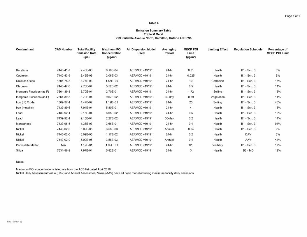
A POI concentration for each significant contaminant emitted from the Facility was calculated based on the emission rates listed in Table 2A and Table 2B and the output from the approved dispersion model presented in Appendix D. The results are presented in Table 4. This Table follows the format provided in the ESDM Procedure Document. For each source of significant contaminants the following parameters are referenced:
• Contaminant name
• CAS number
• Total facility emission rate
• Approved dispersion model used
GHD | Emission Summary and Dispersion Modelling Report | 11201621 (2) | Page 12
• Maximum POI concentration
• Averaging period for the dispersion modelling
• MECP POI limit
• Indication of limiting effect
• Schedule in Regulation 419/05
• The percentage of standard
The POI concentrations listed in Table 4 were compared against criteria listed in the MECP Air Contaminants Benchmarks (ACB) List: Standards, Guidelines, and Screening Levels for Assessing POI Concentrations of Air Contaminants dated April 2018.
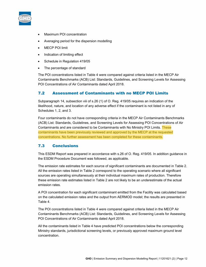
7.2 Assessment of Contaminants with no MECP POI Limits
Subparagraph 14, subsection viii of s.26 (1) of O. Reg. 419/05 requires an indication of the likelihood, nature, and location of any adverse effect if the contaminant is not listed in any of Schedules 1, 2, and 3.
Four contaminants do not have corresponding criteria in the MECP Air Contaminants Benchmarks (ACB) List: Standards, Guidelines, and Screening Levels for Assessing POI Concentrations of Air Contaminants and are considered to be Contaminants with No Ministry POI Limits. These contaminants have been previously reviewed and approved by the MECP at the requested concentrations. No further assessment has been completed for these contaminants.
7.3 Conclusions
This ESDM Report was prepared in accordance with s.26 of O. Reg. 419/05. In addition guidance in the ESDM Procedure Document was followed, as applicable.
The emission rate estimates for each source of significant contaminants are documented in Table 2. All the emission rates listed in Table 2 correspond to the operating scenario where all significant sources are operating simultaneously at their individual maximum rates of production. Therefore these emission rate estimates listed in Table 2 are not likely to be an underestimate of the actual emission rates.
A POI concentration for each significant contaminant emitted from the Facility was calculated based on the calculated emission rates and the output from AERMOD model; the results are presented in Table 4.
The POI concentrations listed in Table 4 were compared against criteria listed in the MECP Air Contaminants Benchmarks (ACB) List: Standards, Guidelines, and Screening Levels for Assessing POI Concentrations of Air Contaminants dated April 2018.
All the contaminants listed in Table 4 have predicted POI concentrations below the corresponding Ministry standards, jurisdictional screening levels, or previously approved maximum ground level concentration.

GHD | Emission Summary and Dispersion Modelling Report | 11201621 (2) | Page 13
This ESDM Report demonstrates that the Facility can operate in compliance with O. Reg. 419/05 using the maximum operating scenarios.
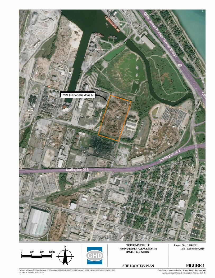
799 Parkdale Ave N
DateProject No.
Filename: \\ghdnet\ghd\CA\Waterloo\Legacy\CAD\drawings\11200000s\11201621\11201621-reports\11201621(001)\11201621(001)GN-WA001.DWGPlot Date: 18 December 2019 3:59 PM
11201621December 2019
FIGURE 1
TRIPLE M METAL LP799 PARKDALE AVENUE NORTH
HAMILTON, ONTARIO
SITE LOCATION PLANData Source: Microsoft Product Screen Shot(s) Reprinted with
permission from Microsoft Corporation, Accessed: 2019.
0 100 200 300m 10000.0000 0.1
N
Redhill Creek
Lake Ontario (lac Ontario)
Troy Ave
Mareve AveDynes Pk
Grace Ave
Leaside Rd
Brampton St
Pier 25 Sout
h Gtwy
Nash Rd N
Brigh
ton Av
e
Tate
Ave
Dunn
Ave
Burge
ss Av
e
Knox
Ave
Burlington St E
Parkd
ale Av
e N
Morley St
Mead Ave
Brampton St
Glow Ave
Burlington Ave
Beach Blvd
Strath
earne
Ave
Dominion Rd
Eastport Blvd
Woodward Ave
Burlington St E
Burland Cres
Hobs
on Rd
Queen Elizabeth Way
Red Hill Valley Pky
Eastport Dr
P ier 2
4 Gtw
y
Queen Elizabeth Way
Windermere Rd
Queen Elizabeth Way
Burlington Street Overpass
Van Wagners Beach Rd
P5
P4
P4
P5
M13
P4
P5P5
M5
M6
P1
P4
M6P5
R-2
C-H/S-1295
G
DE/S-42
C
P1
D/S-571
I1
M6
K
F
P3
M5
P4
I1M6
M5
M13
M14
F-3/S-841AG/S1436b
G/S-321C/S-1435
C/S-1436b
P4
P1
I1
P1
AAA
C/S-1436b
C/S-1435
FIGURE 2
0 70 140 210 280
Meters
Project No.Revision No. -
11201621Date Feb 28, 2020
TRIPLE M METAL LP799 PARKDALE AVENUE NORTH, HAMILTON, ONTARIO
EMISSION SUMMARY AND DISPERSIONMODELLING REPORT
Map Projection: Transverse MercatorHorizontal Datum: North American 1983
Grid: NAD 1983 UTM Zone 17N
DRAFT
Paper Size ANSI B
oData source: City of Hamilton Zoning By-law No. 05-200, Accessed 2020, Google Earth Imagery, Date 2018/07/08 .Q:\GIS\PROJECTS\11201000s\11201621\Layouts\202002_RPT-1-ESDM\11201621_202002_RPT-1-ESDM_GIS001.mxd
Print date: 28 Feb 2020 - 12:25
LegendSite Boundary1 km Radius
City of Hamilton Zoning By-law No. 05-200Waterfront ServicesSpecial Waterfront DistrictCommercialUrban Protected Residential, EtcShipping and Navigation (Ports Lands)ResidentialIndustrialInstitutionalAgriculturalConservationPark and Open Space
LAND USE ZONINGDESIGNATION PLAN
598947.1, 4790749.0
HT=8.0m
S4
S1
S2A
S2B
S3
598777.8, 4790796.5
598761.8, 4790742.1
598768.3, 4790769.5
598769.2, 4790791.8
598728.7, 4790762.4
598665.9, 4790555.1
598654.9, 4790519.1
598643.6, 4790522.1
598655.5, 4790558.4
598621.6, 4790410.0
598814.7, 4790351.5
598843.5, 4790457.3
598866.7, 4790462.6
DateProject No.
Filename: N:\CA\Waterloo\Legacy\CAD\drawings\11200000s\11201621\11201621-reports\11201621(001)\11201621(001)GN-WA003.DWGPlot Date: 28 February 2020 12:56 PM
11201621February 2020
FIGURE 3
TRIPLE M METAL LP799 PARKDALE AVENUE NORTH
HAMILTON, ONTARIO
SOURCE PLAN AND ROOF LAYOUTData Source: Microsoft Product Screen Shot(s) Reprinted with
permission from Microsoft Corporation, Accessed: 2019.
0 25 50 75m 2500.0000 0.4
N
LEGEND
POINT SOURCE LOCATION
S4
S2A VOLUME SOURCE
AREA SOURCES3
PROPERTY BOUNDARY
SHREDDING
STAGE
MAGNETIC
SEPARATION
AIR SEPARATION
STAGE
NON-FERROUS
MATERIAL
FERROUS
MATERIAL
INSPECTION
STAGE
WATER
CYCLONE
S1STOCKPILE
OXY-PROPANE
METAL
CUTTING
S3
ROADS
AND
STORAGE PILES
S4
GENERAL
VENTILATION
SHREDDING
TORCHING GENERAL FACILITY OPERATION
SCRAP
METAL
STOCKPILE
OFF-SITE FOR
FURTHER
PROCESSING
WELDING
REPAIR
DateProject No.
Filename: N:\CA\Waterloo\Legacy\CAD\drawings\11200000s\11201621\11201621-reports\11201621(001)\11201621(001)GN-WA004.DWGPlot Date: 03 March 2020 3:34 PM
11201621March 2020
FIGURE 4a
TRIPLE M METAL LP799 PARKDALE AVENUE NORTH
HAMILTON, ONTARIO
PROCESS FLOW DIAGRAMData Source: URBAN HAMILTON OFFICIAL PLAN, SCHEDULE E-1, URBAN LAND USE DESIGNATIONS.
MATERIAL
DELIVERY TO
STOCKPILES
S2A
SCREENING
HOPPER FRONT
LOADING
SCREENER #1
SCREENER #2
MAGNETIC
DRUM
SEPARATION
STOCKPILE
MAGNETIC
DRUM
SEPARATION
STOCKPILE
FINES
CONVEYOR #1
FINES
CONVEYOR #2
STOCKPILE
MAGNETIC
DRUM
SEPARATION
STOCKPILE
FINES
SCREENER
S2B
SLAG METAL RECOVERY
DateProject No.
Filename: N:\CA\Waterloo\Legacy\CAD\drawings\11200000s\11201621\11201621-reports\11201621(001)\11201621(001)GN-WA004.DWGPlot Date: 28 February 2020 2:24 PM
11201621February 2020
FIGURE 4b
TRIPLE M METAL LP799 PARKDALE AVENUE NORTH
HAMILTON, ONTARIO
PROCESS FLOW DIAGRAMData Source: URBAN HAMILTON OFFICIAL PLAN, SCHEDULE E-1, URBAN LAND USE DESIGNATIONS.
Page 1 of 1
Table 1
Source and Contaminant Identification TableTriple M Metal
799 Parkdale Avenue North, Hamilton, Ontario L8H 7N5
Source ID Source Description General Location Expected Contaminants Significant Rationale
S1 Shredder Cyclone Emissions Particulates, metals Y
S2A Slag metal truck delivery to stockpiles Particulates, metals Y
S2B Slag metal recovery Particulates, metals Y
S3 Oxy-Propane Metal Cutting Welding Fumes (Particulates, metals) Y
S4 Repair Welding Welding Fumes (Particulates, metals) Y
NA On-site roads and storage piles Particulates N MECP Guideline A-10, Table 6.1, BMPP in place at this site.
GHD 11201621 (2)
Page 1 of 1
Table 2
Source Summary Table for the Maximum Emissions ScenarioTriple M Metal
799 Parkdale Avenue North, Hamilton, Ontario L8H 7N5
Contaminant Source Data Emissions Data
Name CAS NumberSource ID Source Description Configuration Flow Rate Diameter
Exhaust Temperature
Height Above Roof
Height Above Grade
Maximum Emission Rate
Averaging Period
Estimation Technique Data Quality
% of Overall Emissions
(m³/s) (m) (°C) (m) (m) E (m) N (m) (g/s)
Beryllium 7440-41-7 S-1 Shredder cyclone Volume NA NA NA NA 8 598770 4790459 3.00E-07 24-hour S A 13%Beryllium 7440-41-7 S-2A Slag metal truck delivery to stockpiles Volume NA NA NA NA 2.75 598753 4790644 8.70E-09 12-hour EF, MB C 0%Beryllium 7440-41-7 S-2B Slag Metal Recovery Volume NA NA NA NA 2.75 598757 4790679 3.97E-08 12-hour EF, MB C 1.7%Beryllium 7440-41-7 S-3 Oxy-Propane Metal Cutting Area NA NA NA NA 1 607294 4843555 2.05E-06 24-hour S A 85%Cadmium 7440-43-9 S-1 Shredder cyclone Volume NA NA NA NA 8 598770 4790459 6.30E-06 24-hour S A 75%Cadmium 7440-43-9 S-2A Slag metal truck delivery to stockpiles Volume NA NA NA NA 2.75 598753 4790644 1.45E-08 12-hour EF, MB C 0.2%Cadmium 7440-43-9 S-2B Slag Metal Recovery Volume NA NA NA NA 2.75 598757 4790679 6.62E-08 12-hour EF, MB C 0.8%Cadmium 7440-43-9 S-3 Oxy-Propane Metal Cutting Area NA NA NA NA 1 607294 4843555 2.05E-06 24-hour S A 24%Calcium Oxide 1305-78-8 S-2A Slag metal truck delivery to stockpiles Volume NA NA NA NA 2.75 598753 4790644 6.77E-04 12-hour EF, MB C 18%Calcium Oxide 1305-78-8 S-2B Slag Metal Recovery Volume NA NA NA NA 2.75 598757 4790679 3.09E-03 12-hour EF, MB C 82%Chromium 7440-47-3 S-1 Shredder cyclone Volume NA NA NA NA 8 598770 4790459 5.57E-05 24-hour S A 21%Chromium 7440-47-3 S-2A Slag metal truck delivery to stockpiles Volume NA NA NA NA 2.75 598753 4790644 1.42E-05 12-hour EF, MB C 5%Chromium 7440-47-3 S-2B Slag Metal Recovery Volume NA NA NA NA 2.75 598757 4790679 6.47E-05 12-hour EF, MB C 24%Chromium 7440-47-3 S-3 Oxy-Propane Metal Cutting Area NA NA NA NA 1 607294 4843555 1.17E-04 24-hour S A 43%Chromium 7440-47-3 S-4 Maintenance Welding Point, Horizontal 0.236 1 20 NA 1.75 598742 4790529 1.81E-05 24-hour EF, MB C 7%Inorganic Fluorides (as F) 7664-39-3 S-4 Maintenance Welding Point, Horizontal 0.236 1 20 NA 1.75 598742 4790529 3.70E-04 24-hour EF, MB C 100%Iron (III) Oxide 1309-37-1 S-1 Shredder cyclone Volume NA NA NA NA 8 598770 4790459 1.21E-02 24-hour S A 27%Iron (III) Oxide 1309-37-1 S-2A Slag metal truck delivery to stockpiles Volume NA NA NA NA 2.75 598753 4790644 7.94E-04 12-hour EF, MB C 2%Iron (III) Oxide 1309-37-1 S-2B Slag Metal Recovery Volume NA NA NA NA 2.75 598757 4790679 3.63E-03 12-hour EF, MB C 8%Iron (III) Oxide 1309-37-1 S-3 Oxy-Propane Metal Cutting Area NA NA NA NA 1 607294 4843555 2.80E-02 24-hour S A 63%Iron (III) Oxide 1309-37-1 S-4 Maintenance Welding Point, Horizontal 0.236 1 20 NA 1.75 598742 4790529 1.21E-04 24-hour EF, MB C 0.3%Iron (metallic) 7439-89-6 S-4 Maintenance Welding Point, Horizontal 0.236 1 20 NA 1.75 598742 4790529 7.94E-04 24-hour EF, MB C 100%Lead 7439-92-1 S-1 Shredder cyclone Volume NA NA NA NA 8 598770 4790459 2.03E-04 24-hour S A 94%Lead 7439-92-1 S-2A Slag metal truck delivery to stockpiles Volume NA NA NA NA 2.75 598753 4790644 1.45E-07 12-hour EF, MB C 0.1%Lead 7439-92-1 S-2B Slag Metal Recovery Volume NA NA NA NA 2.75 598757 4790679 6.62E-07 12-hour EF, MB C 0.3%Lead 7439-92-1 S-3 Oxy-Propane Metal Cutting Area NA NA NA NA 1 607294 4843555 1.13E-05 24-hour S A 5%Manganese 7439-96-5 S-1 Shredder cyclone Volume NA NA NA NA 8 598770 4790459 1.60E-04 24-hour S A 12%Manganese 7439-96-5 S-2A Slag metal truck delivery to stockpiles Volume NA NA NA NA 2.75 598753 4790644 1.35E-04 12-hour EF, MB C 10%Manganese 7439-96-5 S-2B Slag Metal Recovery Volume NA NA NA NA 2.75 598757 4790679 6.16E-04 12-hour EF, MB C 44%Manganese 7439-96-5 S-3 Oxy-Propane Metal Cutting Area NA NA NA NA 1 607294 4843555 2.73E-04 24-hour S A 20%Manganese 7439-96-5 S-4 Maintenance Welding Point, Horizontal 0.236 1 20 NA 1.75 598742 4790529 2.01E-04 24-hour EF, MB C 15%Nickel 7440-02-0 S-1 Shredder cyclone Volume NA NA NA NA 8 598770 4790459 1.99E-05 Annual S A 39%Nickel 7440-02-0 S-2A Slag metal truck delivery to stockpiles Volume NA NA NA NA 2.75 598753 4790644 1.94E-07 12-hour EF, MB C 0%Nickel 7440-02-0 S-2B Slag Metal Recovery Volume NA NA NA NA 2.75 598757 4790679 8.87E-07 12-hour EF, MB C 1.7%Nickel 7440-02-0 S-3 Oxy-Propane Metal Cutting Area NA NA NA NA 1 607294 4843555 1.57E-05 24-hour S A 31%Nickel 7440-02-0 S-4 Maintenance Welding Point, Horizontal 0.236 1 20 NA 1.75 598742 4790529 1.42E-05 24-hour EF, MB C 28%Particulate Matter N/A S-1 Shredder cyclone Volume NA NA NA NA 8 598770 4790459 4.90E-02 24-hour S A 44%Particulate Matter N/A S-2A Slag metal truck delivery to stockpiles Volume NA NA NA NA 2.75 598753 4790644 2.90E-03 12-hour EF, MB C 3%Particulate Matter N/A S-2B Slag Metal Recovery Volume NA NA NA NA 2.75 598757 4790679 1.21E-02 12-hour EF, MB C 11%Particulate Matter N/A S-3 Oxy-Propane Metal Cutting Area NA NA NA NA 1 607294 4843555 4.63E-02 24-hour S A 41%Particulate Matter N/A S-4 Maintenance Welding Point, Horizontal 0.236 1 20 NA 1.75 598742 4790529 1.62E-03 24-hour EF, MB C 1%Silica 7631-86-9 S-4 Maintenance Welding Point, Horizontal 0.236 1 20 NA 1.75 598742 4790529 7.97E-04 24-hour EF, MB C 100%
Notes:1 Estimation technique: S - stack sampling, EF - emission factor, MB - mass balance2 Data quality: A = excellent C = average E = marginal3 Based on 100% load
UTM Coordinates
GHD 11201621 (2)
Page 1 of 1
Table 3
Dispersion Modelling Input Summary TableTriple M Metal
799 Parkdale Avenue North, Hamilton, Ontario L8H 7N5
Relevant section of the regulation
Section title Description of how the approved dispersion model was used
Section 8 Negligible Sources of Contaminant Sources and contaminants that were considered negligible were explicitly identified, and therefore were not modelled, in accordance with s.8 of O. Reg. 419. See Table 1 - Sources and Contaminants Identification Table for more information
Section 9 Same Structure Contamination Not applicable as Triple M is the onlytenant occupying the property and does nothave a childcare facility, healthcare facility, senior's residence, long-term care facility,or an educational facility located at the Facility.
Section 10 Operating Conditions Daily maximum operations were assumed. See Section 4.1 and Appendix A of the ESDM Report. Conditions modelled represent a worst-case 24-hour operation.
Section 11 Source of Contaminant Emission Rate The emission rate for each significant contaminant emitted from a significant source was estimated, the methodology for the calculation is documented in Table 2 - Source Summary Table. See Section 4.1 and Section 4.2 and Appendix A of the ESDM Report for more information.
Section 12 Combined Effect of Assumptions for Operating Conditions and Emission Rates
The operating conditions were estimated in accordance with s.10(1) and 1 and S.11 (1) 1 of O. Reg. 419 and are therefore considered to result in the highest concentrations at POI that the Facility is capable of for the contaminants emitted. See Section 4.1 and Section 4.2 of the ESDM Report.
Section 13 Meteorological Conditions Site Specific MET Data provided by the MECP has been applied.
Section 14 Area of Modelling Coverage Receptor grid and property boundary receptors were defined as defined byO. Reg. 419/05
Section 15 Stack Height Actual stack emission point height, per ADMGO
Section 16 Terrain Data The Canadian Digital Elevation Model (CDEM) data in GeoTIFF format that included the Hamliton area was used (030M)
Section 17 Averaging Periods Appropriate averaging periods were selectedfor each contaminant to demonstratecompliance with the O. Reg. 419/05 Schedule 3 standards.
GHD 11201621 (2)
Page 1 of 1
Table 4
Emission Summary TableTriple M Metal
799 Parkdale Avenue North, Hamilton, Ontario L8H 7N5
Contaminant CAS Number Total Facility Emission Rate
Maximum POI Concentration
Air Dispersion Model Used
Averaging Period
MECP POI Limit
Limiting Effect Regulation Schedule Percentage of MECP POI Limit
(g/s) (µg/m³) (µg/m³)
Beryllium 7440-41-7 2.40E-06 8.10E-04 AERMOD v19191 24-hr 0.01 Health B1 - Sch. 3 8%
Cadmium 7440-43-9 8.43E-06 2.06E-03 AERMOD v19191 24-hr 0.025 Health B1 - Sch. 3 8%
Calcium Oxide 1305-78-8 3.77E-03 1.55E+00 AERMOD v19191 24-hr 10 Corrosion B1 - Sch. 3 16%
Chromium 7440-47-3 2.70E-04 5.52E-02 AERMOD v19191 24-hr 0.5 Health B1 - Sch. 3 11%
Inorganic Fluorides (as F) 7664-39-3 3.70E-04 2.70E-01 AERMOD v19191 24-hr 1.72 Soiling B1 - Sch. 3 16%
Inorganic Fluorides (as F) 7664-39-3 3.70E-04 9.67E-02 AERMOD v19191 30-day 0.69 Vegetation B1 - Sch. 3 14%
Iron (III) Oxide 1309-37-1 4.47E-02 1.12E+01 AERMOD v19191 24-hr 25 Soiling B1 - Sch. 3 45%
Iron (metallic) 7439-89-6 7.94E-04 5.80E-01 AERMOD v19191 24-hr 4 Health B1 - Sch. 3 15%
Lead 7439-92-1 2.15E-04 6.05E-02 AERMOD v19191 24-hr 0.5 Health B1 - Sch. 3 12%
Lead 7439-92-1 2.15E-04 2.27E-02 AERMOD v19191 30-day 0.2 Health B1 - Sch. 3 11%
Manganese 7439-96-5 1.38E-03 3.66E-01 AERMOD v19191 24-hr 0.4 Health B1 - Sch. 3 91%
Nickel 7440-02-0 5.09E-05 3.58E-03 AERMOD v19191 Annual 0.04 Health B1 - Sch. 3 9%
Nickel 7440-02-0 5.09E-05 1.17E-02 AERMOD v19191 24-hr 0.2 Health DAV 6%
Nickel 7440-02-0 5.09E-05 3.58E-03 AERMOD v19191 Annual 0.4 Health AAV <1%
Particulate Matter N/A 1.12E-01 1.99E+01 AERMOD v19191 24-hr 120 Visibility B1 - Sch. 3 17%
Silica 7631-86-9 7.97E-04 5.82E-01 AERMOD v19191 24-hr 3 Health B2 - MD 19%
Notes:
Maximum POI concentrations listed are from the ACB list dated April 2018. Nickel Daily Assessment Value (DAV) and Annual Assessment Value (AAV) have all been modelled using maximum facility daily emissions
GHD 11201621 (2)

GHD | Emission Summary and Dispersion Modelling Report | 11201621 (2)
Appendices
GHD | Emission Summary and Dispersion Modelling Report | 11201621 (2)
Appendix A Supporting Calculations
Shredder Emissions
Shredder
Species CAS No.
Shredder Cyclone Emission Rates
(g/s)Antimony 7440-36-0 1.10E-05Arsenic 7440-38-2 2.40E-06Barium 7440-39-3 8.22E-05Beryllium 7440-41-7 3.00E-07Cadmium 7440-43-9 6.30E-06Chromium 7440-47-3 5.57E-05Cobalt 7440-48-4 9.70E-06Iron (treated as ferric oxide) 1309-37-1 1.21E-02Lead 7439-92-1 2.03E-04Manganese 7439-96-5 1.60E-04Mercury 7439-97-6 1.20E-05Nickel 7440-02-0 1.99E-05Particulate Matter N/A 4.90E-02Selenium 7782-49-2 3.00E-05Silver 7440-22-4 5.00E-07Tin 7440-31-5 3.86E-05Vanadium 7440-62-2 2.40E-06
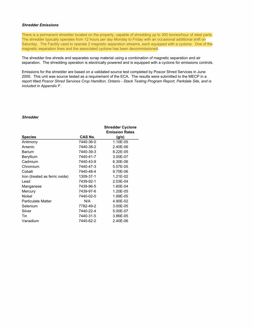
There is a permanent shredder located on the property, capable of shredding up to 300 tonnes/hour of steel parts. The shredder typically operates from 12 hours per day Monday to Friday with an occasional additional shift on Saturday. The Facility used to operate 2 magnetic separation streams, each equipped with a cyclone. One of the magnetic separation lines and the associated cyclone has been decommissioned.
The shredder line shreds and separates scrap material using a combination of magnetic separation and air separation. The shredding operation is electrically powered and is equipped with a cyclone for emissions controls.
Emissions for the shredder are based on a validated source test completed by Poscor Shred Services in June 2005. This unit was source tested as a requirement of the ECA. The results were submitted to the MECP in a report titled Poscor Shred Services Crop Hamilton, Ontario - Stack Testing Program Report, Parkdale Site, and is included in Appendix F .
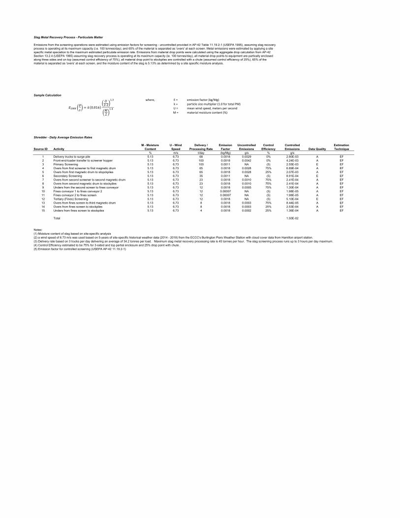
Slag Metal Recovery Process - Particulate Matter
Sample Calculation
where, E = emission factor (kg/Mg)
k = particle size multiplier (1.0 for total PM)
U = mean wind speed, meters per second
M = material moisture content (%)
Shredder - Daily Average Emission Rates
Source ID ActivityM - Moisture
ContentU - Wind Speed
Delivery / Processing Rate
Emission Factor
Uncontrolled Emissions
Control Efficiency
Controlled Emissions Data Quality
Estimation Technique
% m/s t/day (kg/Mg) g/s % g/s1 Delivery trucks to surge pile 5.13 6.73 68 0.0018 0.0029 0% 2.90E-03 A EF2 Front-end-loader transfer to screener hopper 5.13 6.73 100 0.0018 0.0042 0% 4.24E-03 A EF3 Primary Screening 5.13 6.73 100 0.0011 NA (5) 2.55E-03 E EF4 Overs from first screener to first magnetic drum 5.13 6.73 65 0.0018 0.0028 75% 6.89E-04 A EF5 Overs from first magnetic drum to stopckpiles 5.13 6.73 65 0.0018 0.0028 25% 2.07E-03 A EF6 Secondary Screening 5.13 6.73 35 0.0011 NA (5) 8.91E-04 E EF7 Overs from second screener to second magnetic drum 5.13 6.73 23 0.0018 0.0010 75% 2.41E-04 A EF8 Overs from second magnetic drum to stockpiles 5.13 6.73 23 0.0018 0.0010 75% 2.41E-04 A EF9 Unders from the second screen to fines conveyor 5.13 6.73 12 0.0018 0.0005 75% 1.30E-04 A EF10 Fines conveyor 1 to fines conveyor 2 5.13 6.73 12 0.00007 NA (5) 1.98E-05 A EF11 Fines conveyor 2 to fines screen 5.13 6.73 12 0.00007 NA (5) 1.98E-05 A EF12 Tertiary (Fines) Screening 5.13 6.73 12 0.0018 NA (5) 5.10E-04 E EF13 Overs from fines screen to third magnetic drum 5.13 6.73 8 0.0018 0.0003 75% 8.44E-05 A EF14 Overs from fines screen to stockpiles 5.13 6.73 8 0.0018 0.0003 25% 2.53E-04 A EF15 Unders from fines screen to stockpiles 5.13 6.73 4 0.0018 0.0002 25% 1.36E-04 A EF
Total 1.50E-02
Notes:(1) Moisture content of slag based on site-specific analysis(2) a wind speed of 6.73 m/s was used based on 5-years of site-specific historical weather data (2014 - 2018) from the ECCC's Burlington Piers Weather Station with cloud cover data from Hamilton airport station.(3) Delivery rate based on 3 trucks per day delivering an average of 34.2 tonnes per load. Maximum slag metal recovery processing rate is 45 tonnes per hour. The slag screening process runs up to 3 hours per day maximum.(4) Control Efficiency estimated to be 75% for 3-sided and top partial enclosure and 25% drop point with chute.(5) Emission factor for controlled screening (USEPA AP-42 11.19.2-1)
Emissions from the screening operations were estimated using emission factors for screening - uncontrolled provided in AP-42 Table 11.19.2-1 (USEPA 1995), assuming slag recovery process is operating at its maximum capacity (i.e. 100 tonnes/day); and 65% of the material is separated as 'overs' at each screen. Metal emissions were estimated by applying a site specific metal speciation to the maximum estimated particulate emission rate. Emissions from material drop points were calculated using the aggregate drop calculation from AP-42 Section 13.2.4 (USEPA 1985) assuming slag recovery process is operating at its maximum capacity (ie. 100 tonnes/day), all material drop points to equipment are partically enclosed along three sides and on top (assumed control efficiency of 75%), all material drop point to stockpiles are controlled with a chute (assumed control efficiency of 25%), 65% of the material is separated as 'overs' at each screen, and the moisture content of the slag is 5.13% as determined by a site specific moisture analysis.
0.0162.2
.
2
.
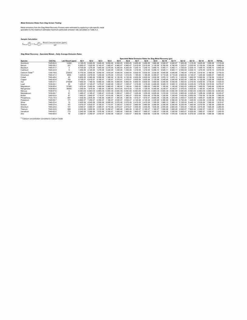
Metal Emission Rates from Slag Screen Testing
Sample Calculation
Slag Metal Recovery - Speciated Metals - Daily Average Emission Rates
Speciated Metal Emission Rates for Slag Metal Recovery (g/s)Species CAS No. Lab Result (ppm) S2-1 S2-2 S2-3 S2-4 S2-5 S2-6 S2-7 S2-8 S2-9 S2-10 S2-11 S2-12 S2-13 S2-14 S2-15 TOTALAluminum 7429-90-5 14300 4.15E-05 6.06E-05 3.64E-05 9.85E-06 2.95E-05 2.95E-05 3.45E-06 3.45E-06 1.86E-06 2.84E-07 2.84E-07 7.30E-06 1.21E-06 3.62E-06 1.95E-06 2.31E-04Barium 7440-39-3 241 6.99E-07 1.02E-06 6.14E-07 1.66E-07 4.98E-07 4.98E-07 5.81E-08 5.81E-08 3.13E-08 4.78E-09 4.78E-09 1.23E-07 2.03E-08 6.10E-08 3.28E-08 3.89E-06Beryllium 7440-41-7 3 8.70E-09 1.27E-08 7.64E-09 2.07E-09 6.20E-09 6.20E-09 7.23E-10 7.23E-10 3.89E-10 5.95E-11 5.95E-11 1.53E-09 2.53E-10 7.59E-10 4.09E-10 4.84E-08Cadmium 7440-43-9 5 1.45E-08 2.12E-08 1.27E-08 3.44E-09 1.03E-08 1.03E-08 1.21E-09 1.21E-09 6.49E-10 9.92E-11 9.92E-11 2.55E-09 4.22E-10 1.27E-09 6.81E-10 8.07E-08Calcium Oxide (1) 1305-78-8 233633 6.77E-04 9.90E-04 5.95E-04 1.61E-04 4.83E-04 4.83E-04 5.63E-05 5.63E-05 3.03E-05 4.64E-06 4.64E-06 1.19E-04 1.97E-05 5.91E-05 3.18E-05 3.77E-03Chromium 7440-47-3 4890 1.42E-05 2.07E-05 1.25E-05 3.37E-06 1.01E-05 1.01E-05 1.18E-06 1.18E-06 6.35E-07 9.71E-08 9.71E-08 2.50E-06 4.13E-07 1.24E-06 6.66E-07 7.89E-05Cobalt 7440-48-4 20 5.80E-08 8.48E-08 5.09E-08 1.38E-08 4.13E-08 4.13E-08 4.82E-09 4.82E-09 2.60E-09 3.97E-10 3.97E-10 1.02E-08 1.69E-09 5.06E-09 2.73E-09 3.23E-07Copper 7440-50-8 163 4.73E-07 6.91E-07 4.15E-07 1.12E-07 3.37E-07 3.37E-07 3.93E-08 3.93E-08 2.12E-08 3.24E-09 3.24E-09 8.32E-08 1.38E-08 4.13E-08 2.22E-08 2.63E-06Iron 1309-37-1 274000 7.94E-04 1.16E-03 6.98E-04 1.89E-04 5.66E-04 5.66E-04 6.60E-05 6.60E-05 3.56E-05 5.44E-06 5.44E-06 1.40E-04 2.31E-05 6.93E-05 3.73E-05 4.42E-03Lead 7439-92-1 50 1.45E-07 2.12E-07 1.27E-07 3.44E-08 1.03E-07 1.03E-07 1.21E-08 1.21E-08 6.49E-09 9.92E-10 9.92E-10 2.55E-08 4.22E-09 1.27E-08 6.81E-09 8.07E-07Magnesium 7439-95-4 57500 1.67E-04 2.44E-04 1.46E-04 3.96E-05 1.19E-04 1.19E-04 1.39E-05 1.39E-05 7.46E-06 1.14E-06 1.14E-06 2.93E-05 4.85E-06 1.46E-05 7.84E-06 9.28E-04Manganese 7439-96-5 46500 1.35E-04 1.97E-04 1.18E-04 3.20E-05 9.61E-05 9.61E-05 1.12E-05 1.12E-05 6.04E-06 9.23E-07 9.23E-07 2.37E-05 3.92E-06 1.18E-05 6.34E-06 7.51E-04Mercury 7439-97-6 0 0.00E+00 0.00E+00 0.00E+00 0.00E+00 0.00E+00 0.00E+00 0.00E+00 0.00E+00 0.00E+00 0.00E+00 0.00E+00 0.00E+00 0.00E+00 0.00E+00 0.00E+00 0.00E+00Molybdenum 7439-98-7 51 1.48E-07 2.16E-07 1.30E-07 3.51E-08 1.05E-07 1.05E-07 1.23E-08 1.23E-08 6.62E-09 1.01E-09 1.01E-09 2.60E-08 4.30E-09 1.29E-08 6.95E-09 8.23E-07Nickel 7440-02-0 67 1.94E-07 2.84E-07 1.71E-07 4.61E-08 1.38E-07 1.38E-07 1.62E-08 1.62E-08 8.70E-09 1.33E-09 1.33E-09 3.42E-08 5.65E-09 1.70E-08 9.13E-09 1.08E-06Phosphorus 7723-14-0 667 1.93E-06 2.83E-06 1.70E-06 4.59E-07 1.38E-06 1.38E-06 1.61E-07 1.61E-07 8.66E-08 1.32E-08 1.32E-08 3.40E-07 5.63E-08 1.69E-07 9.09E-08 1.08E-05Potassium 7440-09-7 171 4.96E-07 7.25E-07 4.35E-07 1.18E-07 3.53E-07 3.53E-07 4.12E-08 4.12E-08 2.22E-08 3.39E-09 3.39E-09 8.73E-08 1.44E-08 4.33E-08 2.33E-08 2.76E-06Silver 7440-22-4 10 2.90E-08 4.24E-08 2.55E-08 6.89E-09 2.07E-08 2.07E-08 2.41E-09 2.41E-09 1.30E-09 1.98E-10 1.98E-10 5.10E-09 8.44E-10 2.53E-09 1.36E-09 1.61E-07Sodium 7440-23-5 161 4.67E-07 6.82E-07 4.10E-07 1.11E-07 3.33E-07 3.33E-07 3.88E-08 3.88E-08 2.09E-08 3.20E-09 3.20E-09 8.22E-08 1.36E-08 4.07E-08 2.19E-08 2.60E-06Strontium 7440-24-6 141 4.09E-07 5.98E-07 3.59E-07 9.71E-08 2.91E-07 2.91E-07 3.40E-08 3.40E-08 1.83E-08 2.80E-09 2.80E-09 7.20E-08 1.19E-08 3.57E-08 1.92E-08 2.28E-06Titanium 7440-32-6 908 2.63E-06 3.85E-06 2.31E-06 6.25E-07 1.88E-06 1.88E-06 2.19E-07 2.19E-07 1.18E-07 1.80E-08 1.80E-08 4.63E-07 7.66E-08 2.30E-07 1.24E-07 1.47E-05Vanadium 7440-62-2 773 2.24E-06 3.28E-06 1.97E-06 5.32E-07 1.60E-06 1.60E-06 1.86E-07 1.86E-07 1.00E-07 1.53E-08 1.53E-08 3.95E-07 6.52E-08 1.96E-07 1.05E-07 1.25E-05Zinc 7440-66-6 79 2.29E-07 3.35E-07 2.01E-07 5.44E-08 1.63E-07 1.63E-07 1.90E-08 1.90E-08 1.03E-08 1.57E-09 1.57E-09 4.03E-08 6.67E-09 2.00E-08 1.08E-08 1.28E-06
(1) Calcium concentration converted to Calcium Oxide
Metal emissions from the Slag Metal Recovery Process were estimated by applycing a site-specific metal speciation to the maximum estimated maximum particulate emission rate calculated on Table A.2.
10
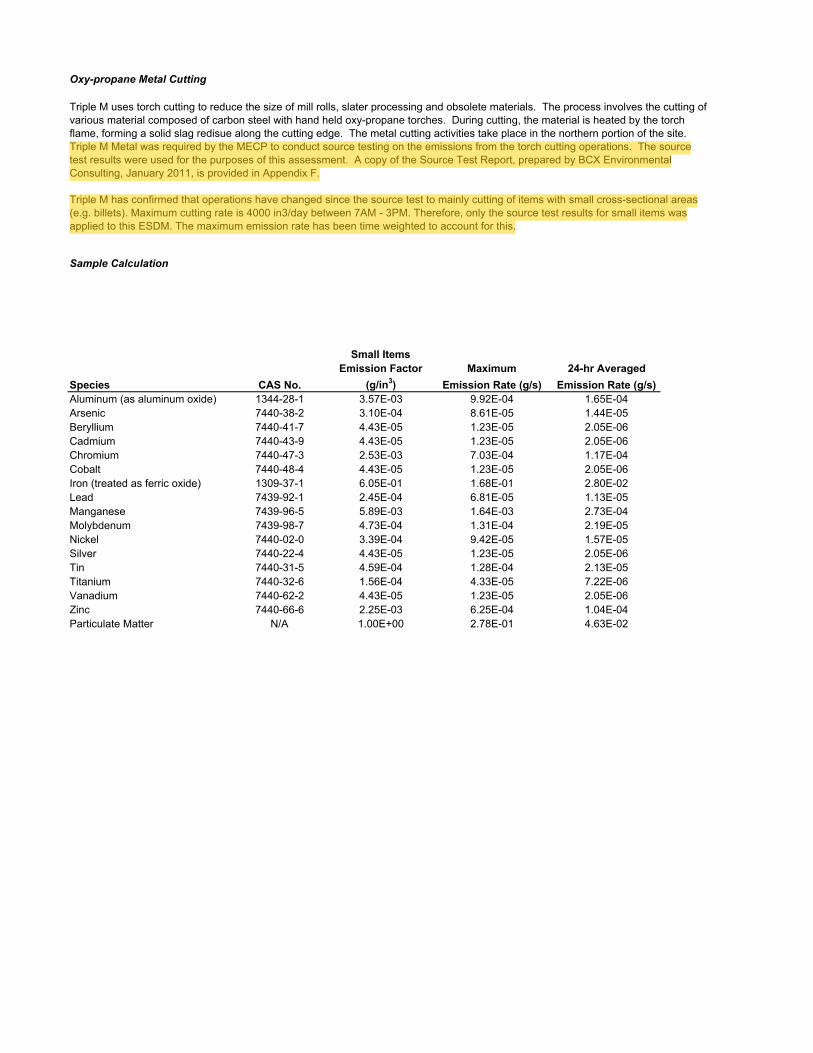
Oxy-propane Metal Cutting
Sample Calculation
Small ItemsEmission Factor Maximum 24-hr Averaged
Species CAS No. (g/in3) Emission Rate (g/s) Emission Rate (g/s)Aluminum (as aluminum oxide) 1344-28-1 3.57E-03 9.92E-04 1.65E-04Arsenic 7440-38-2 3.10E-04 8.61E-05 1.44E-05Beryllium 7440-41-7 4.43E-05 1.23E-05 2.05E-06Cadmium 7440-43-9 4.43E-05 1.23E-05 2.05E-06Chromium 7440-47-3 2.53E-03 7.03E-04 1.17E-04Cobalt 7440-48-4 4.43E-05 1.23E-05 2.05E-06Iron (treated as ferric oxide) 1309-37-1 6.05E-01 1.68E-01 2.80E-02Lead 7439-92-1 2.45E-04 6.81E-05 1.13E-05Manganese 7439-96-5 5.89E-03 1.64E-03 2.73E-04Molybdenum 7439-98-7 4.73E-04 1.31E-04 2.19E-05Nickel 7440-02-0 3.39E-04 9.42E-05 1.57E-05Silver 7440-22-4 4.43E-05 1.23E-05 2.05E-06Tin 7440-31-5 4.59E-04 1.28E-04 2.13E-05Titanium 7440-32-6 1.56E-04 4.33E-05 7.22E-06Vanadium 7440-62-2 4.43E-05 1.23E-05 2.05E-06Zinc 7440-66-6 2.25E-03 6.25E-04 1.04E-04Particulate Matter N/A 1.00E+00 2.78E-01 4.63E-02
Triple M uses torch cutting to reduce the size of mill rolls, slater processing and obsolete materials. The process involves the cutting of various material composed of carbon steel with hand held oxy-propane torches. During cutting, the material is heated by the torch flame, forming a solid slag redisue along the cutting edge. The metal cutting activities take place in the northern portion of the site. Triple M Metal was required by the MECP to conduct source testing on the emissions from the torch cutting operations. The source test results were used for the purposes of this assessment. A copy of the Source Test Report, prepared by BCX Environmental Consulting, January 2011, is provided in Appendix F.
Triple M has confirmed that operations have changed since the source test to mainly cutting of items with small cross-sectional areas (e.g. billets). Maximum cutting rate is 4000 in3/day between 7AM - 3PM. Therefore, only the source test results for small items was applied to this ESDM. The maximum emission rate has been time weighted to account for this.
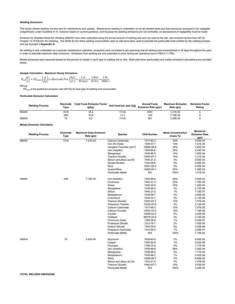
Welding Emissions
Sample Calculation - Maximum Hourly Emissions
Where: EFfume is the published emission rate (AP-42) for that type of welding and consumable
Particulate Emission Calculation
Welding ProcessElectrode
TypeTotal Fume Emission Factor
(g/kg)Amt Used per year (kg)
Annual Fume Emission Rate (g/yr)
Maximum Emission Rate (g/s)
Emission Factor Rating
SMAW 7018 18.4 113.6 2091 1.21E-03 C308 10.8 11.4 123 7.10E-05 C
GMAW 70 5.2 113.6 591 3.42E-04 A
Metals Emission Calculation
Welding ProcessElectrode
TypeMaximum Daily Emission
Rate (g/s)Species CAS Number
Metal Concentration (mass %)
Maximum Emission Rate
(g/s)SMAW 7018 1.21E-03 Calcium Carbonate 1317-65-3 30% 3.63E-04
Iron (III) Oxide 1309-37-1 10% 1.21E-04Inorganic Fluorides (as F) 16984-48-8 30% 3.63E-04Iron (metallic) 7439-89-6 35% 4.24E-04Manganese 7439-96-5 15% 1.82E-04Titanium Dioxide 13463-67-7 10% 1.21E-04Silicon and alloys (as Si) 7440-21-3 5% 6.05E-05Silicate Binders 1334-09-8 5% 6.05E-05Mica 12001-26-2 5% 6.05E-05Quartz/Silica 14808-60-7 60% 7.26E-04Particulate Matter N/A 100% 1.21E-03
SMAW 308 7.10E-05 Iron (metallic) 7439-89-6 50% 3.55E-05Chromium 7440-47-3 25% 1.78E-05Nickel 7440-02-0 20% 1.42E-05Manganese 7439-96-5 3% 2.13E-06Silicon 7440-21-3 1% 7.10E-07Molybdenum 7439-98-7 4% 2.84E-06Columbium 7440-03-1 3% 2.13E-06Titanium Dioxide 13463-67-7 15% 1.07E-05Potassium Titanate 12030-97-6 3% 2.13E-06Calcium Carbonate 1317-65-3 15% 1.07E-05Calcium Fluoride 14542-23-5 10% 7.10E-06Cryolite 15096-52-3 5% 3.55E-06Feldspar 68476-25-5 3% 2.13E-06Chromium Oxide 1308-38-9 1% 3.55E-07Potassium Silicate 1312-76-1 2% 1.42E-06Sodium Silicate 1344-09-8 5% 3.55E-06Potassium Hydroxide 1310-58-3 1% 3.55E-07Particulate Matter N/A 100% 7.10E-05
GMAW 70 3.42E-04 Aluminum 7429-90-5 2% 6.84E-06Copper 7440-50-8 1% 3.42E-06Fluorspar 7789-75-5 5% 1.71E-05Iron (metallic) 7439-89-6 98% 3.35E-04Manganese 7439-96-5 5% 1.71E-05Molybdenum 7439-98-7 1% 3.42E-06Silica 14808-60-7 2% 6.84E-06Silicon and alloys (as Si) 7440-21-3 4% 1.37E-05Titanium Dioxide 13463-67-7 10% 3.42E-05Particulate Matter N/A 100% 3.42E-04
TOTAL WELDING EMISSIONS
The facility utilizes welding rod and wire for maintenance and upkeep. Maintenance welding is undertaken on an as-needed basis and was previously assessed to be negligible (insignificant) under Guideline A-10, however based on current guidance, and because the welding emissions are not controlled, an assessment of negligibility must be made.
Emission for Shielded Metal Arc Welding (SMAW) have been estimated using the annual amount of welding wire and rod used at the site, and emission factors from AP-42 Chapter 12.19 Electric Arc Welding. The SDSs for the three welding consumables used on site have been used to speciate the particulate fume emitted by the welding process, and are included in Appendix G.
As welding is only undertaken as a periodic maintenance operation, emissions were converted to g/s assuming that all welding was accomplished in 30 days throughout the year, in order to estimate maximum daily emissions. Emissions from welding are only expected to occur during site operating hours (7AM to 11 PM).
Metals emissions were assumed based on the percent of metals in each type of welding rod or wire. Both total fume (particulate) and metals emissions calculations are provided below.
1
30116
13600
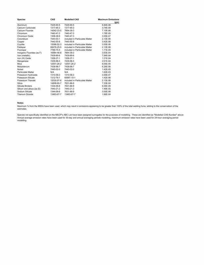
Species CAS Modelled CAS Maximum Emissions (g/s)
Aluminum 7429-90-5 7429-90-5 6.84E-06Calcium Carbonate 1317-65-3 1317-65-3 3.74E-04Calcium Fluoride 14542-23-5 7664-39-3 7.10E-06Chromium 7440-47-3 7440-47-3 1.78E-05Chromium Oxide 1308-38-9 7440-47-3 3.55E-07Columbium 7440-03-1 included in Particulate Matter 2.13E-06Copper 7440-50-8 7440-50-8 3.42E-06Cryolite 15096-52-3 included in Particulate Matter 3.55E-06Feldspar 68476-25-5 included in Particulate Matter 2.13E-06Fluorspar 7789-75-5 included in Particulate Matter 1.71E-05Inorganic Fluorides (as F) 16984-48-8 7664-39-3 3.63E-04Iron (metallic) 7439-89-6 7439-89-6 7.94E-04Iron (III) Oxide 1309-37-1 1309-37-1 1.21E-04Manganese 7439-96-5 7439-96-5 2.01E-04Mica 12001-26-2 12001-26-2 6.05E-05Molybdenum 7439-98-7 7439-98-7 6.26E-06Nickel 7440-02-0 7440-02-0 1.42E-05Particulate Matter N/A N/A 1.62E-03Potassium Hydroxide 1310-58-3 1310-58-3 3.55E-07Potassium Silicate 1312-76-1 65997-15-1 1.42E-06Potassium Titanate 12030-97-6 included in Particulate Matter 2.13E-06Silica 14808-60-7 7631-86-9 7.33E-04Silicate Binders 1334-09-8 7631-86-9 6.05E-05Silicon and alloys (as Si) 7440-21-3 7440-21-3 7.49E-05Sodium Silicate 1344-09-8 7631-86-9 3.55E-06Titanium Dioxide 13463-67-7 13463-67-7 1.66E-04
Notes:
Maximum % from the MSDs have been used, which may result in emissions appearing to be greater than 100% of the total welding fume, adding to the conservatism of the estimates.
Species not specifically identified on the MECP's ABC List have been assigned surrogates for the purposes of modelling. These are identified as "Modelled CAS Number" aboveAnnual average emission rates have been used for 30-day and annual averaging periods modelling, maximum emission rates have been used for 24-hour averaging period modelling
GHD | Emission Summary and Dispersion Modelling Report | 11201621 (2)
Appendix B Supporting Information for Assessment of
Negligibility
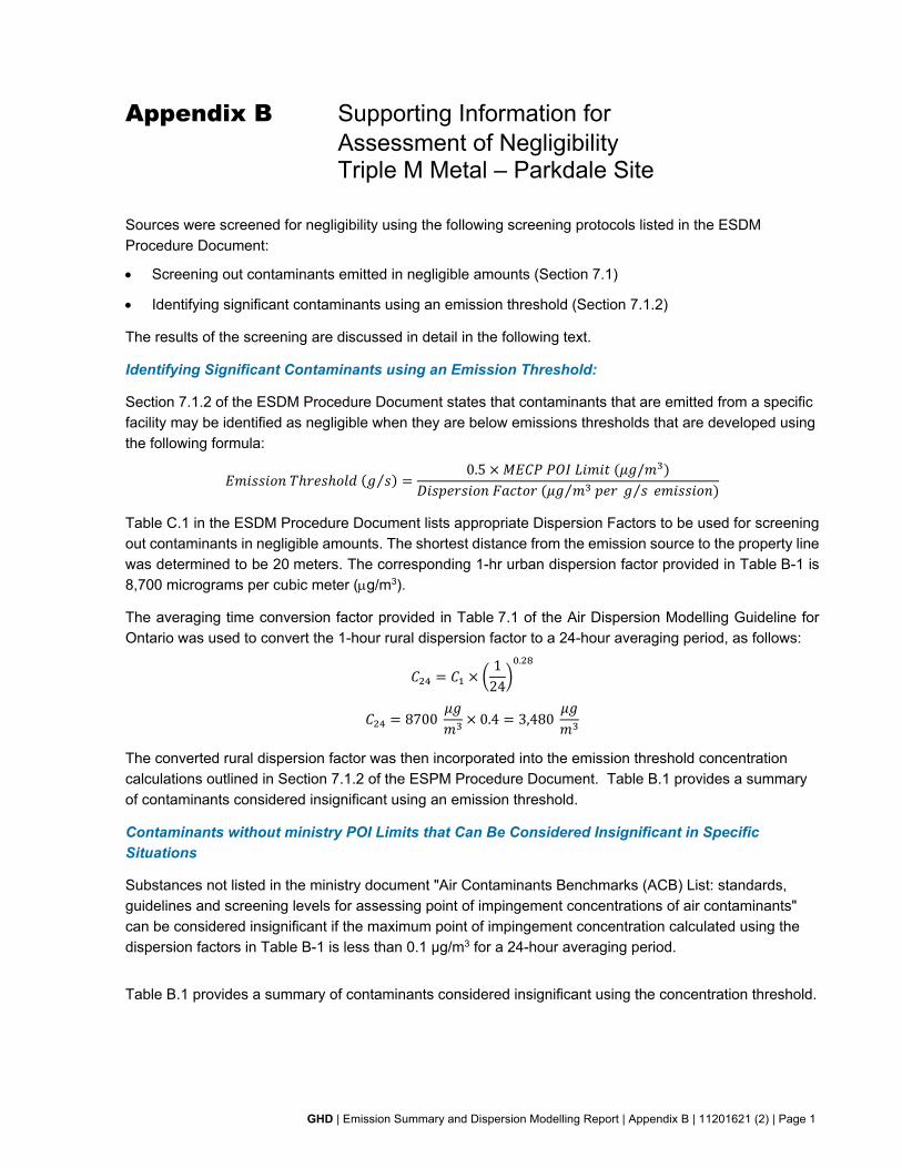
GHD | Emission Summary and Dispersion Modelling Report | Appendix B | 11201621 (2) | Page 1
Appendix B Supporting Information for Assessment of Negligibility Triple M Metal – Parkdale Site
Sources were screened for negligibility using the following screening protocols listed in the ESDM Procedure Document:
Screening out contaminants emitted in negligible amounts (Section 7.1)
Identifying significant contaminants using an emission threshold (Section 7.1.2)
The results of the screening are discussed in detail in the following text.
Identifying Significant Contaminants using an Emission Threshold:
Section 7.1.2 of the ESDM Procedure Document states that contaminants that are emitted from a specific facility may be identified as negligible when they are below emissions thresholds that are developed using the following formula:
⁄0.5 /
⁄ ⁄
Table C.1 in the ESDM Procedure Document lists appropriate Dispersion Factors to be used for screening out contaminants in negligible amounts. The shortest distance from the emission source to the property line was determined to be 20 meters. The corresponding 1-hr urban dispersion factor provided in Table B-1 is 8,700 micrograms per cubic meter (g/m3).
The averaging time conversion factor provided in Table 7.1 of the Air Dispersion Modelling Guideline for Ontario was used to convert the 1-hour rural dispersion factor to a 24-hour averaging period, as follows:
124
.
8700 0.4 3,480
The converted rural dispersion factor was then incorporated into the emission threshold concentration calculations outlined in Section 7.1.2 of the ESPM Procedure Document. Table B.1 provides a summary of contaminants considered insignificant using an emission threshold.
Contaminants without ministry POI Limits that Can Be Considered Insignificant in Specific
Situations
Substances not listed in the ministry document "Air Contaminants Benchmarks (ACB) List: standards, guidelines and screening levels for assessing point of impingement concentrations of air contaminants" can be considered insignificant if the maximum point of impingement concentration calculated using the dispersion factors in Table B-1 is less than 0.1 µg/m3 for a 24-hour averaging period.
Table B.1 provides a summary of contaminants considered insignificant using the concentration threshold.
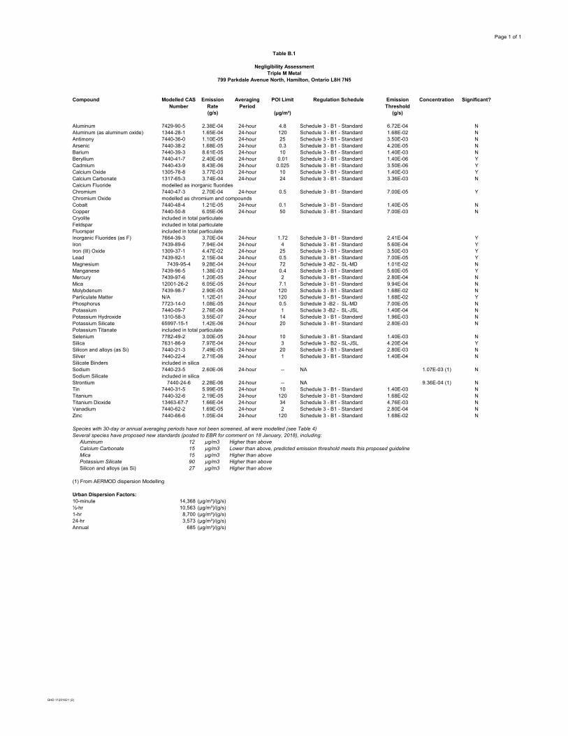
Page 1 of 1
Table B.1
Negligibility AssessmentTriple M Metal
799 Parkdale Avenue North, Hamilton, Ontario L8H 7N5
Compound Modelled CAS Number
Emission Rate
Averaging Period
POI Limit Regulation Schedule Emission Threshold
Concentration Significant?
(g/s) (µg/m³) (g/s)
Aluminum 7429-90-5 2.38E-04 24-hour 4.8 Schedule 3 - B1 - Standard 6.72E-04 NAluminum (as aluminum oxide) 1344-28-1 1.65E-04 24-hour 120 Schedule 3 - B1 - Standard 1.68E-02 NAntimony 7440-36-0 1.10E-05 24-hour 25 Schedule 3 - B1 - Standard 3.50E-03 NArsenic 7440-38-2 1.68E-05 24-hour 0.3 Schedule 3 - B1 - Standard 4.20E-05 NBarium 7440-39-3 8.61E-05 24-hour 10 Schedule 3 - B1 - Standard 1.40E-03 NBeryllium 7440-41-7 2.40E-06 24-hour 0.01 Schedule 3 - B1 - Standard 1.40E-06 YCadmium 7440-43-9 8.43E-06 24-hour 0.025 Schedule 3 - B1 - Standard 3.50E-06 YCalcium Oxide 1305-78-8 3.77E-03 24-hour 10 Schedule 3 - B1 - Standard 1.40E-03 YCalcium Carbonate 1317-65-3 3.74E-04 24-hour 24 Schedule 3 - B1 - Standard 3.36E-03 NCalcium Fluoride modelled as inorganic fluoridesChromium 7440-47-3 2.70E-04 24-hour 0.5 Schedule 3 - B1 - Standard 7.00E-05 YChromium Oxide modelled as chromium and compoundsCobalt 7440-48-4 1.21E-05 24-hour 0.1 Schedule 3 - B1 - Standard 1.40E-05 NCopper 7440-50-8 6.05E-06 24-hour 50 Schedule 3 - B1 - Standard 7.00E-03 NCryolite included in total particulateFeldspar included in total particulateFluorspar included in total particulateInorganic Fluorides (as F) 7664-39-3 3.70E-04 24-hour 1.72 Schedule 3 - B1 - Standard 2.41E-04 YIron 7439-89-6 7.94E-04 24-hour 4 Schedule 3 - B1 - Standard 5.60E-04 YIron (III) Oxide 1309-37-1 4.47E-02 24-hour 25 Schedule 3 - B1 - Standard 3.50E-03 YLead 7439-92-1 2.15E-04 24-hour 0.5 Schedule 3 - B1 - Standard 7.00E-05 YMagnesium 7439-95-4 9.28E-04 24-hour 72 Schedule 3 -B2 - SL-MD 1.01E-02 NManganese 7439-96-5 1.38E-03 24-hour 0.4 Schedule 3 - B1 - Standard 5.60E-05 YMercury 7439-97-6 1.20E-05 24-hour 2 Schedule 3 - B1 - Standard 2.80E-04 NMica 12001-26-2 6.05E-05 24-hour 7.1 Schedule 3 - B1 - Standard 9.94E-04 NMolybdenum 7439-98-7 2.90E-05 24-hour 120 Schedule 3 - B1 - Standard 1.68E-02 NParticulate Matter N/A 1.12E-01 24-hour 120 Schedule 3 - B1 - Standard 1.68E-02 YPhosphorus 7723-14-0 1.08E-05 24-hour 0.5 Schedule 3 -B2 - SL-MD 7.00E-05 NPotassium 7440-09-7 2.76E-06 24-hour 1 Schedule 3 -B2 - SL-JSL 1.40E-04 NPotassium Hydroxide 1310-58-3 3.55E-07 24-hour 14 Schedule 3 - B1 - Standard 1.96E-03 NPotassium Silicate 65997-15-1 1.42E-06 24-hour 20 Schedule 3 - B1 - Standard 2.80E-03 NPotassium Titanate included in total particulateSelenium 7782-49-2 3.00E-05 24-hour 10 Schedule 3 - B1 - Standard 1.40E-03 NSilica 7631-86-9 7.97E-04 24-hour 3 Schedule 3 - B2 - SL-JSL 4.20E-04 YSilicon and alloys (as Si) 7440-21-3 7.49E-05 24-hour 20 Schedule 3 - B1 - Standard 2.80E-03 NSilver 7440-22-4 2.71E-06 24-hour 1 Schedule 3 - B1 - Standard 1.40E-04 NSilicate Binders included in silicaSodium 7440-23-5 2.60E-06 24-hour -- NA 1.07E-03 (1) NSodium Silicate included in silicaStrontium 7440-24-6 2.28E-06 24-hour -- NA 9.36E-04 (1) NTin 7440-31-5 5.99E-05 24-hour 10 Schedule 3 - B1 - Standard 1.40E-03 NTitanium 7440-32-6 2.19E-05 24-hour 120 Schedule 3 - B1 - Standard 1.68E-02 NTitanium Dioxide 13463-67-7 1.66E-04 24-hour 34 Schedule 3 - B1 - Standard 4.76E-03 NVanadium 7440-62-2 1.69E-05 24-hour 2 Schedule 3 - B1 - Standard 2.80E-04 NZinc 7440-66-6 1.05E-04 24-hour 120 Schedule 3 - B1 - Standard 1.68E-02 N
Species with 30-day or annual averaging periods have not been screened, all were modelled (see Table 4)Several species have proposed new standards (posted to EBR for comment on 18 January, 2018), including: Aluminum 12 µg/m3 Higher than above Calcium Carbonate 15 µg/m3 Lower than above, predicted emission threshold meets this proposed guideline Mica 15 µg/m3 Higher than above Potassium Silicate 90 µg/m3 Higher than above Silicon and alloys (as Si) 27 µg/m3 Higher than above
(1) From AERMOD dispersion Modelling
Urban Dispersion Factors:10-minute 14,368 (μg/m³)/(g/s)½-hr 10,563 (μg/m³)/(g/s)1-hr 8,700 (μg/m³)/(g/s)24-hr 3,573 (μg/m³)/(g/s)Annual 685 (μg/m³)/(g/s)
GHD 11201621 (2)
GHD | Emission Summary and Dispersion Modelling Report | 11201621 (2)
Appendix C Environmental Compliance Approval
No. 4483-7T2P53
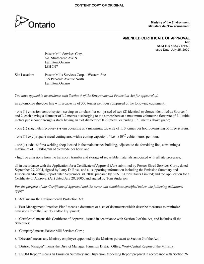
Ministry of the EnvironmentMinistère de l’Environnement
AMENDED CERTIFICATE OF APPROVALAIR
NUMBER 4483-7T2P53Issue Date: July 25, 2009
Poscor Mill Services Corp.670 Strathearne Ave NHamilton, OntarioL8H 7N7
Site Location: Poscor Mills Services Corp. - Western Site799 Parkdale Avenue NorthHamilton, Ontario
You have applied in accordance with Section 9 of the Environmental Protection Act for approval of:
an automotive shredder line with a capacity of 300 tonnes per hour comprised of the following equipment:
- one (1) emission control system serving an air classifier comprised of two (2) identical cyclones, identified as Sources 1and 2, each having a diameter of 3.2 metres discharging to the atmosphere at a maximum volumetric flow rate of 7.1 cubicmetres per second through a stack having an exit diameter of 0.20 metre, extending 17.0 metres above grade;
- one (1) slag metal recovery system operating at a maximum capacity of 110 tonnes per hour, consisting of three screens;
- one (1) oxy-propane metal cutting area with a cutting capacity of 1.64 x l0-2 cubic metres per hour;
- one (1) exhaust for a welding shop located in the maintenance building, adjacent to the shredding line, consuming amaximum of 1.0 kilogram of electrode per hour; and
- fugitive emissions from the transport, transfer and storage of recyclable materials associated with all site processes;
all in accordance with the Application for a Certificate of Approval (Air) submitted by Poscor Shred Services Corp., datedSeptember 27, 2004, signed by Larry D. Rose, and all supporting information including the Emission Summary andDispersion Modelling Report dated September 30, 2004, prepared by SENES Consultants Limited; and the Application for aCertificate of Approval (Air) dated July 28, 2005, and signed by Tom Anderson.
For the purpose of this Certificate of Approval and the terms and conditions specified below, the following definitionsapply:
1. "Act" means the Environmental Protection Act;
2. "Best Management Practices Plan" means a document or a set of documents which describe measures to minimizeemissions from the Facility and/or Equipment;
3. "Certificate" means this Certificate of Approval, issued in accordance with Section 9 of the Act, and includes all theSchedules;
4. "Company" means Poscor Mill Services Corp.;
5. "Director" means any Ministry employee appointed by the Minister pursuant to Section 5 of the Act;
6. "District Manager" means the District Manager, Hamilton District Office, West-Central Region of the Ministry;
7. "ESDM Report" means an Emission Summary and Dispersion Modelling Report prepared in accordance with Section 26
CONTENT COPY OF ORIGINAL
of O. Reg. 419/05, the Procedure Document, and this Certificate;
8. "Equipment" means all the equipment and sources of emissions described in the Company's application, this Certificateand in the supporting documentation submitted with the application, to the extent approved by this Certificate;
9. "Facility" means the entire operation located on the property where the Equipment is located;
10. "Independent Consultant" means a consultant not representing the Company, and not involved in the daily opacitymeasurements at the Facility;
11. "Manager" means the Manager, Technology Standards Section, Standards Development Branch, or any other personwho represents and carries out the duties of the Manager, Technology Standards Section, Standards Development Branch,as those duties relate to the conditions of this Certificate;
12. "Manual" means a document or a set of documents that provide written instructions to staff of the Company;
13. "Ministry" means the Ontario Ministry of the Environment;
14. "O.Reg. 419/05" means the Ontario Regulation 419/05, Air Pollution – Local Air Quality;
15. "Opacity Measurement Plan" means a plan for the measurement of opacity, prepared in accordance with the proceduresin Schedule "B";
16. "Opacity Technical Bulletin" means the Ministry document titled "Technical Methods for Opacity under O. Reg. 419"dated April 2008, as amended;
17. "Pre-Test Plan" means a plan for the Source Testing including the information required in Section 1.1 of the SourceTesting Code;
18. "Procedure Document" means Ministry document titled "Procedure for Preparing an Emission Summary and DispersionModelling Report" dated March 2009, as amended.
19. "Publication NPC-205" means Publication NPC-205, Sound Level Limits for Stationary Sources in Class 1 & 2 Areas(Urban), October, 1995;
20. "Source Testing" means sampling and testing to measure emissions resulting from operating the Equipment at a level oftypical maximum production within the approved operating range of the Equipment which satisfies paragraph 1 ofsubsection 11(1) of O. Reg. 419/05;
21. "Source Testing Code" means the Source Testing Code, Version 2, Report No. ARB-66-80, dated November 1980,prepared by the Ministry, as amended;
22. "Targeted Sources" means the oxy-propane metal cutting area; and
23. "Test Contaminants" mean aluminium, arsenic, beryllium, cadmium, chromium, cobalt, iron, lead, manganese,molybdenum, nickel, silver, suspended particulate matter, tin, titanium, vanadium, and zinc.
You are hereby notified that this approval is issued to you subject to the terms and conditions outlined below:
TERMS AND CONDITIONS
OPERATION AND MAINTENANCE
1. The Company shall ensure that the Equipment is properly operated and maintained at all times. The Company shall:
(1) prepare, not later than three (3) months after the date of this Certificate, and update, as necessary, a Manual outliningthe operating procedures and a maintenance program for the Equipment, including:
(a) routine operating and maintenance procedures in accordance with good engineering practices and as
CONTENT COPY OF ORIGINAL
recommended by the Equipment suppliers;
(b) emergency procedures;
(c) procedures for any record keeping activities relating to operation and maintenance of the Equipment;
(d) all appropriate measures to minimize noise and odorous emissions from all potential sources;
(2) implement the recommendations of the Manual.
BEST MANAGEMENT PRACTICES PLAN FOR FUGITIVE DUST
2. The Company shall ensure that reasonable efforts are made to keep the access road used by vehicles to enter and leavethe Facility free of mud, dirt, dust and waste.
3. The Company shall develop, in consultation with the District Manager and acceptable to the Director, a BestManagement Practices Plan for the control of fugitive dust emissions. This Best Management Practices Plan shall include,but not be limited to:
(1) identification of the main sources of fugitive dust emissions such as:
(a) on-site traffic;
(b) paved roads/areas;
(c) unpaved roads/areas;
(d) material stock piles;
(e) loading/unloading areas and loading/unloading techniques;
(f) material spills;
(g) material conveyance systems;
(h) exposed openings in process and storage buildings; and
(i) general work areas.
(2) potential causes for high dust emissions and opacity resulting from these sources;
(3) preventative and control measures in place or under development to minimize the likelihood of high dust emissions andopacity from the sources of fugitive dust emissions identified above. Details of the preventative and control measures shallinclude:
(a) a description of the control equipment to be installed;
(b) a description of the preventative procedures to be implemented; and/or
(c) the frequency of occurrence of periodic preventative activities, including material application rates, asapplicable.
(4) measures to control fugitive dust emissions from on-site sources including, but not limited to on-site roads, stockpiledmaterial and yard operations. If necessary, the major sources of dust shall be treated with water and/or dust suppressionmaterials to minimize the overall dust emissions from the Facility;
(5) a truck tire cleaning station to minimize the tracking of on-site dirt and dust onto off-site public roads;
CONTENT COPY OF ORIGINAL
(6) an implementation schedule for the Best Management Practices Plan, including training of Facility personnel;
(7) inspection and maintenance procedures and monitoring initiatives to ensure effective implementation of the preventativeand control measures; and
(8) a list of all Ministry comments received, if any, on the development of the Best Management Practices Plan, and adescription of how each Ministry comment was addressed in the Best Management Practices Plan.
4. The Company shall submit the Best Management Practices Plan to the Director and the District Manager not later thansix (6) months after the date of this Certificate.
(1) The Director may not accept the Best Management Practices Plan if the minimum requirements described in thisCertificate were not included in the Best Management Practices Plan;
(2) If the Best Management Practices Plan is not accepted by the Director, the Company shall submit a Best ManagementPractices Plan acceptable to the Director not later than nine (9) months after the date of this Certificate.
5. Upon acceptance of the Best Management Practices Plan by the Director, the Company shall immediately implement theBest Management Practices Plan for the control of fugitive dust emissions to provide effective dust suppression measuresto any potential sources of fugitive dust emissions resulting from the operation of the Facility.
NOISE
6. The Company shall ensure that the noise emissions from the Facility comply with the limits set in Publication NPC-205.
BEST MANAGEMENT PRACTICES PLAN FOR METAL CUTTING AND OPACITY
7. The Company shall perform opacity measurements of emissions from the oxy-propane metal cutting area in accordancewith the Opacity Measurement Plan.
(1) Opacity measurements shall be:
(a) performed at least once daily;
(b) performed during daytime hours;
(c) performed for visible emissions from the oxy-propane metal cutting area;
(d) performed during times when emissions from the oxy-propane metal cutting area are occurring; and
(e) recorded in the log book;
(2) Opacity measurements shall be performed during:
(a) times when the oxy-propane metal cutting area is operating at the maximum daily cutting capacity;
(b) times when the visible fume emissions from the oxy-propane metal cutting area are at their maximum; or
(c) times of very low wind speeds (periods of calm winds, with wind speeds less than 1 metre per second).
8. The Company shall perform periodic verification of opacity measurements by an Independent Consultant, in accordancewith the Opacity Measurement Plan. These measurements are to be performed at least once every six (6) months, andmust be:
(1) performed during times when the oxy-propane metal cutting area is operating at the maximum daily cutting capacity;
CONTENT COPY OF ORIGINAL
(2) recorded in the log book; and
(3) performed simultaneously with opacity measurements that are required under Condition 7.
9. The Company shall develop, in consultation with the Manager and the District Manager and acceptable to the Director, aBest Management Practices Plan for the control of emissions from oxy-propane metal cutting at the Facility. This BestManagement Practices Plan shall include, but not be limited to:
(1) procedures to minimize emissions of visible fumes and odorous emissions from the oxy-propane metal cutting area;
(2) potential causes for visible fumes and high opacity resulting from the oxy-propane metal cutting area;
(3) preventative and control measures in place or under development to minimize the likelihood of visible fumes and highopacity from the oxy-propane metal cutting area. Details of the preventative and control measures shall include:
(a) a description of the control equipment to be installed;
(b) a description of the preventative procedures to be implemented; and/or
(c) the frequency of occurrence of periodic preventative activities, including material application rates, asapplicable;
(4) an implementation schedule for the Best Management Practices Plan, including training of Facility personnel;
(5) inspection and maintenance procedures and monitoring initiatives to ensure effective implementation of the preventativeand control measures; and
(6) a list of all Ministry comments received, if any, on the development of the Best Management Practices Plan, and adescription of how each Ministry comment was addressed in the Best Management Practices Plan.
10. The Company shall submit the Best Management Practices Plan to the Director and the District Manager not later thansix (6) months after the date of this Certificate.
(1) The Director may not accept the Best Management Practices Plan if the minimum requirements described in thisCertificate were not included in the Best Management Practices Plan.
(2) If the Best Management Practices Plan is not accepted by the Director, the Company shall submit a Best ManagementPractices Plan acceptable to the Director not later than nine (9) months after the date of this Certificate.
11. Upon acceptance of the Best Management Practices Plan by the Director, the Company shall immediately implementthe Best Management Practices Plan for the control of emissions from the oxy-propane metal cutting area resulting fromthe operation of the Facility.
SOURCE TESTING
12. The Company shall perform Source Testing, in accordance with the procedures in Schedule "A" to determine the rateof emission of the Test Contaminants from the Targeted Sources.
UPDATED ESDM REPORT
13. The Company shall, no later than three (3) months after completing the Source Testing, submit to the District Managerand Director an updated ESDM Report, prepared in accordance with Section 26 of O. Reg. 419/05, incorporating theresults of the Source Testing.
DOCUMENTATION REQUIREMENTS
CONTENT COPY OF ORIGINAL
14. The Company shall record, in a log book, each time a specific preventative and control measure described in each BestManagement Practices Plan is implemented. The Company shall record, as a minimum:
(1) the date when each emission control measure is installed, including a description of the control measure;
(2) the date when each new preventative measure or operating procedure to minimize emissions is implemented, includinga description of the preventative measure or operating procedure; and
(3) the date, time of commencement, and time of completion of each periodic activity conducted to minimize emissions,including a description of the preventative measure/procedure and the name of the individual performing the periodicactivity.
RECORD RETENTION
15. The Company shall retain, for a minimum of two (2) years from the date of their creation, all records and informationrelated to or resulting from the recording activities required by this Certificate, and make these records available for reviewby staff of the Ministry upon request. The Company shall retain:
(1) all records on the maintenance, repair and inspection of the Equipment;
(2) the log book which contains all records on the preventative and control measures implemented for each source offugitive dust emission identified in the Best Management Practices Plan
(3) all records on the environmental complaints; including:
(a) a description, time, date and location of each incident;
(b) wind direction and other weather conditions at the time of the incident;
(c) the name(s) of Company personnel responsible for handling the incident;
(d) the cause of the incident;
(e) the Company response to the incident; and
(f) a description of the measures taken to address the cause of the incident and to prevent a similar occurrencein the future, and the outcome of the measures taken.
NOTIFICATION OF COMPLAINTS
16. The Company shall notify the District Manager, in writing, of each environmental complaint within two (2) businessdays of the complaint. The notification shall include:
(1) a description of the nature of the complaint;
(2) the time, date and location of the incident;
(3) the wind direction and other weather conditions at the time of the incident; and
(4) the name(s) of Company personnel responsible for handling the incident.SCHEDULE "A"
Source Testing Procedures
1. The Company shall submit, not later than two (2) months after the date of this Certificate, to the Manager a Pre-Test Plan for the SourceTesting of the Targeted Sources. The Company shall finalize the Pre-Test Plan in consultation with the Manager.
2. The Company shall not commence the Source Testing required under this Certificate until the Manager has approved the Pre-Test Plan.
CONTENT COPY OF ORIGINAL
3. The Company shall complete the Source Testing not later than three (3) months after the Manager has approved the Pre-Test Plan.
4. The Company shall notify the Manager, the District Manager and the Director in writing of the location, date and time of any impendingSource Testing required by this Certificate, at least fifteen (15) days prior to the Source Testing.
5. The Company shall submit a report (hardcopy and electronic format) on the Source Testing to the Manager, the District Manager and theDirector not later than three (3) months after completing the Source Testing. The report shall be in the format described in the Source TestingCode, and shall also include, but not be limited to:(1) an executive summary;(2) an identification of the applicable North American Industry Classification System code (NAICS) for the Facility;(3) records of operating conditions at the time of Source Testing;(4) results of Source Testing, including the emission rate, emission concentration, and relevant emission factor of the Test Contaminants from theTargeted Sources; and(5) a tabular comparison of Source Testing results for the Targeted Sources and Test Contaminants to original emission estimates described in theCompany's application and the ESDM Report.
6. The Director may not accept the results of the Source Testing if:(1) the Source Testing Code or the requirements of the Manager were not followed;(2) the Company did not notify the Manager, the District Manager and Director of the Source Testing; or(3) the Company failed to provide a complete report on the Source Testing.
7. If the Director does not accept the results of the Source Testing, the Director may require re-testing. If re-testing is required, the Pre-Test Planstrategies need to be revised and submitted to the Manager for approval. The actions taken to minimize the possibility of the Source Testingresults not being accepted by the Director must be noted in the revised Pre-Test Plan submission to the Manager.
8. If the Source Testing results indicate the emission estimates are higher than the original emission estimates described in the Company’sapplication and the ESDM Report, the Company shall update their ESDM Report in accordance with Section 26 of O. Reg. 419/05 with theemission estimates from the source testing report and make these records available for review by staff of the Ministry upon request. The updatedEmission Summary Table from the updated ESDM Report shall be submitted with the report on the Source Testing.
SCHEDULE "B"Opacity Measurement Procedure
1. The Company shall submit, not later than four (4) months after the date of this Certificate, to the Manager, District Manager and the Directora draft Opacity Measurement Plan, detailing the methodology that the Facility will implement to perform opacity measurements as required inthis Certificate.
2. The Company shall develop the plan in accordance with the Opacity Technical Bulletin, as applicable. The plan shall include, but not belimited to, detailed information on the opacity measurement method, how the opacity measurements will be made, and training of Facilitypersonnel to perform and record the opacity measurements.
3. The Company shall finalize the draft plan in consultation with the Manager, and include a list of all Ministry comments received, if any, onthe development of the Opacity Measurement Plan, and a description of how each Ministry comment was addressed in the OpacityMeasurement Plan.
4. The Company shall submit the finalized Opacity Measurement Plan to the Manager, District Manager and the Director for approval. TheManager may accept the plan, or require the Company to make changes to the plan such that the plan is acceptable to the Manager.
5. Once the Manager has accepted the plan, the Company shall implement the Opacity Measurement Plan immediately, and make the planavailable for review by staff of the Ministry upon request.
6. If the verification of opacity measurements performed by the Independent Consultant, as required by this Certificate, are higher than the dailyopacity measurements that were measured simultaneously, the Company shall revise the Opacity Measurement Plan and submit a draft OpacityMeasurement Plan to the Manager, District Manager and the Director, and follow the procedure outlined in this Schedule to finalize the plan.
The reasons for the imposition of these terms and conditions are as follows:
1. Condition Nos. 1, 2, 3, 4 and 5 are included to emphasize that the Equipment must be maintained and operatedaccording to a procedure that will result in compliance with the Act, the Regulations and this Certificate.
CONTENT COPY OF ORIGINAL
2. Condition No. 6 is included to outline the minimum performance requirements considered necessary to prevent anadverse effect resulting from the operation of the Equipment.
3. Condition Nos. 7, 8, 9, 10 and 11 are included to emphasize that the Targeted Sources must be maintained and operatedaccording to a procedure that will result in compliance with the Act, the Regulations and this Certificate.
4. Condition Nos. 12 and 13 are included to require the Company to gather and retain accurate information so thatcompliance with the Act, the regulations and this Certificate can be verified.
5. Condition Nos. 14 and 15 are included to require the Company to keep records and to provide information to staff of theMinistry so that compliance with the Act, the Regulations and this Certificate can be verified.
6. Condition No. 16 is included to require the Company to notify staff of the Ministry so that compliance with the Act, theRegulations and this Certificate can be verified.
This Certificate of Approval revokes and replaces Certificate(s) of Approval No. 8480-6PMR9Z issued on August17, 2006
In accordance with Section 139 of the Environmental Protection Act, R.S.O. 1990, Chapter E-19, as amended, you may bywritten notice served upon me and the Environmental Review Tribunal within 15 days after receipt of this Notice, requirea hearing by the Tribunal. Section 142 of the Environmental Protection Act, provides that the Notice requiring the hearingshall state:
1. The portions of the approval or each term or condition in the approval in respect of which the hearing is required, and;2. The grounds on which you intend to rely at the hearing in relation to each portion appealed.
The Notice should also include:
3. The name of the appellant;4. The address of the appellant;5. The Certificate of Approval number;6. The date of the Certificate of Approval;7. The name of the Director;8. The municipality within which the works are located;
And the Notice should be signed and dated by the appellant.
This Notice must be served upon:
The Secretary*Environmental Review Tribunal655 Bay Street, 15th FloorToronto, OntarioM5G 1E5
AND The DirectorSection 9, Environmental Protection ActMinistry of the Environment2 St. Clair Avenue West, Floor 12AToronto, OntarioM4V 1L5
* Further information on the Environmental Review Tribunal’s requirements for an appeal can be obtained directly from theTribunal at: Tel: (416) 314-4600, Fax: (416) 314-4506 or www.ert.gov.on.ca
The above noted works are approved under Section 9 of the Environmental Protection Act.
DATED AT TORONTO this 25th day of July, 2009Victor Low, P.Eng.DirectorSection 9, Environmental Protection Act
CONTENT COPY OF ORIGINAL

SH/c: District Manager, MOE Hamilton - DistrictLarry Rose, Poscor Mill Services Corp.
CONTENT COPY OF ORIGINAL
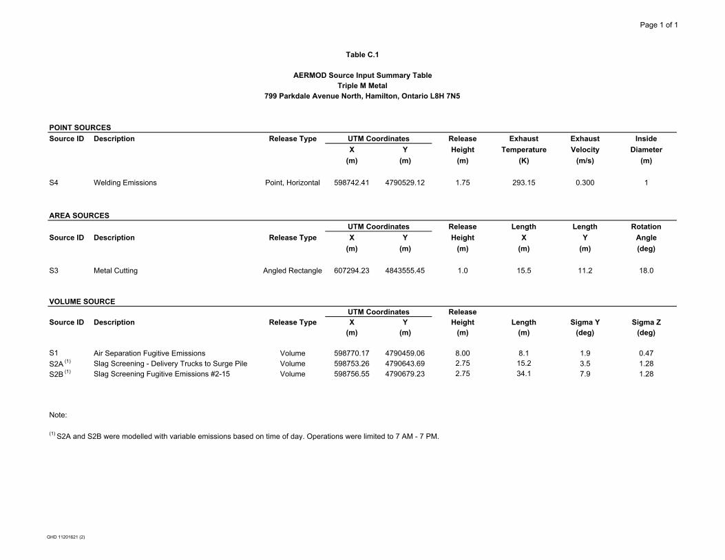
Page 1 of 1
POINT SOURCES
Source ID Description Release Type UTM Coordinates Release Exhaust Exhaust Inside
X Y Height Temperature Velocity Diameter
(m) (m) (m) (K) (m/s) (m)
S4 Welding Emissions Point, Horizontal 598742.41 4790529.12 1.75 293.15 0.300 1
AREA SOURCES
UTM Coordinates Release Length Length Rotation
Source ID Description Release Type X Y Height X Y Angle
(m) (m) (m) (m) (m) (deg)
S3 Metal Cutting Angled Rectangle 607294.23 4843555.45 1.0 15.5 11.2 18.0
VOLUME SOURCEUTM Coordinates Release
Source ID Description Release Type X Y Height Length Sigma Y Sigma Z(m) (m) (m) (m) (deg) (deg)
S1 Air Separation Fugitive Emissions Volume 598770.17 4790459.06 8.00 8.1 1.9 0.47S2A (1) Slag Screening - Delivery Trucks to Surge Pile Volume 598753.26 4790643.69 2.75 15.2 3.5 1.28S2B (1) Slag Screening Fugitive Emissions #2-15 Volume 598756.55 4790679.23 2.75 34.1 7.9 1.28
Note:
(1) S2A and S2B were modelled with variable emissions based on time of day. Operations were limited to 7 AM - 7 PM.
Table C.1
AERMOD Source Input Summary TableTriple M Metal
799 Parkdale Avenue North, Hamilton, Ontario L8H 7N5
GHD 11201621 (2)
GHD | Emission Summary and Dispersion Modelling Report | 11201621 (2)
Appendix D Dispersion Modelling Files
(Electronic)
GHD | Emission Summary and Dispersion Modelling Report | 11201621 (2)
Appendix E Shredder June 2005 Source Test Report
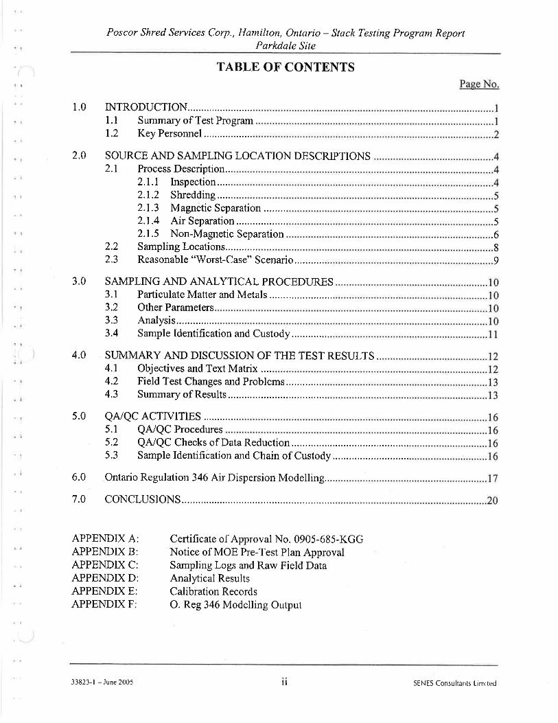
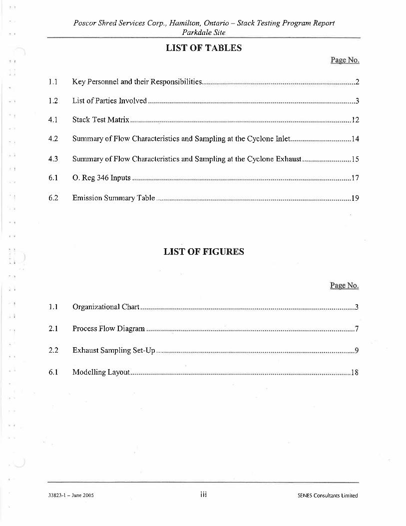
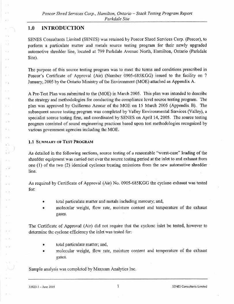
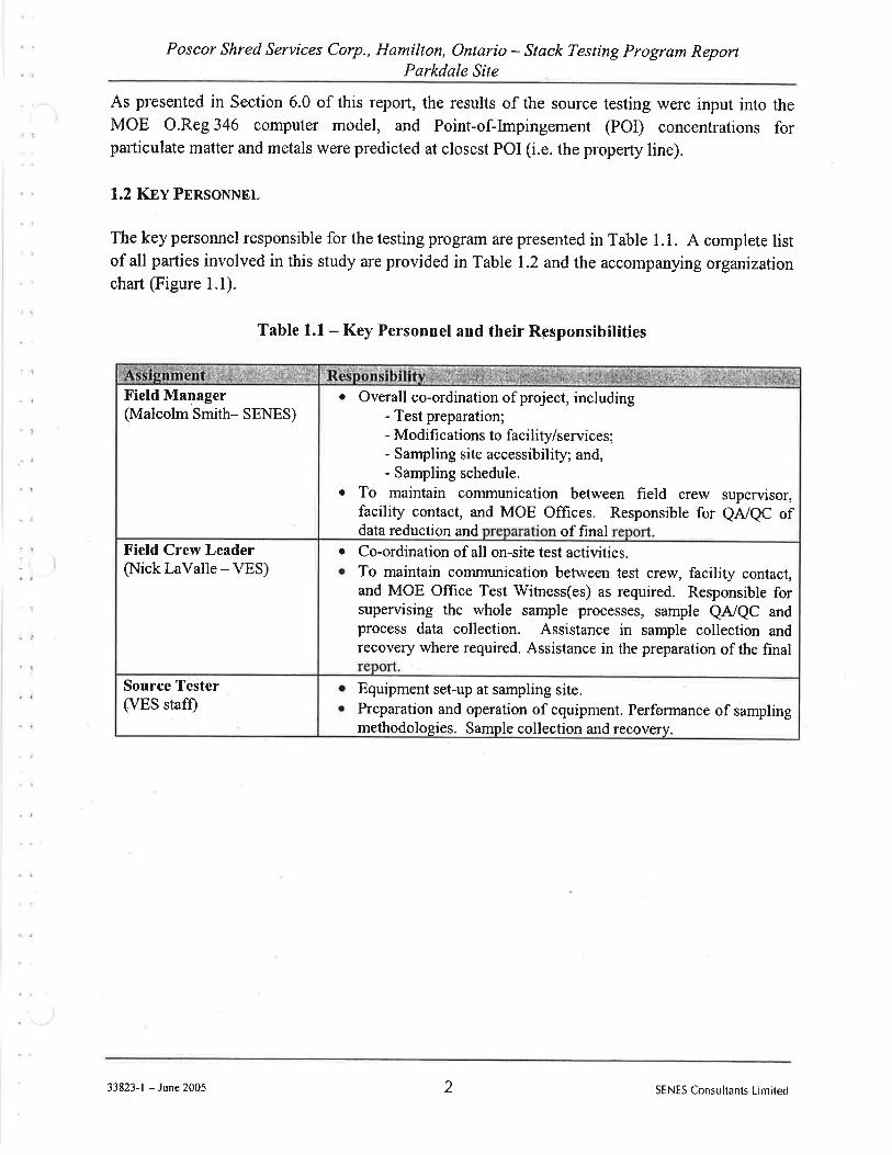
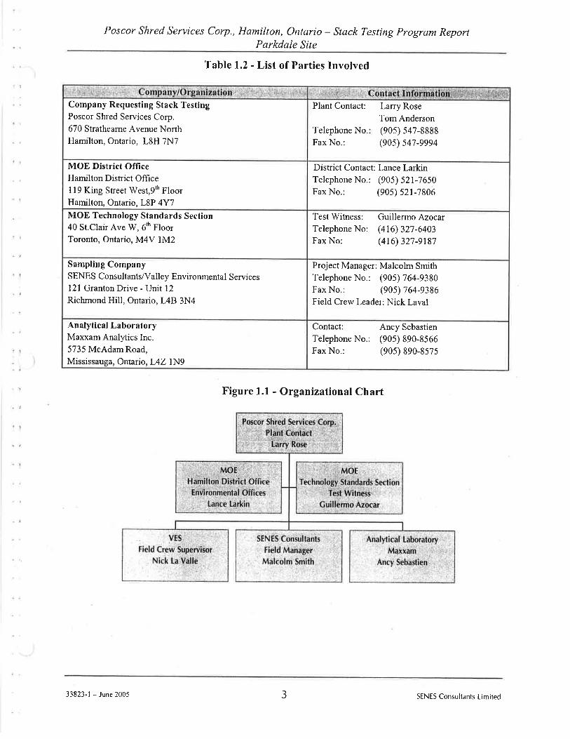
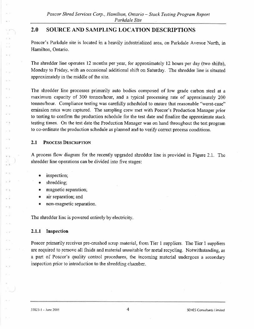
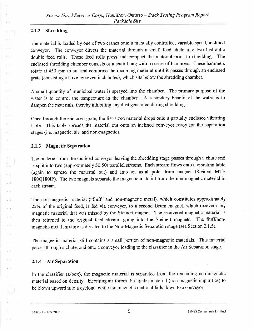
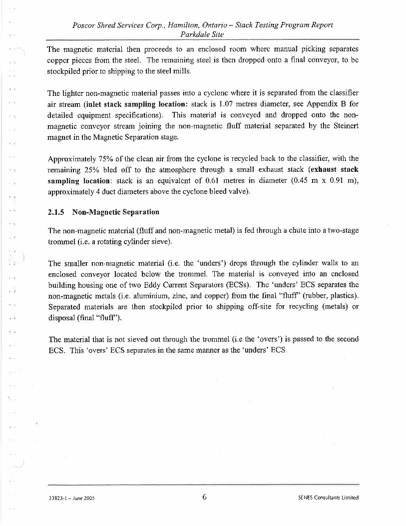
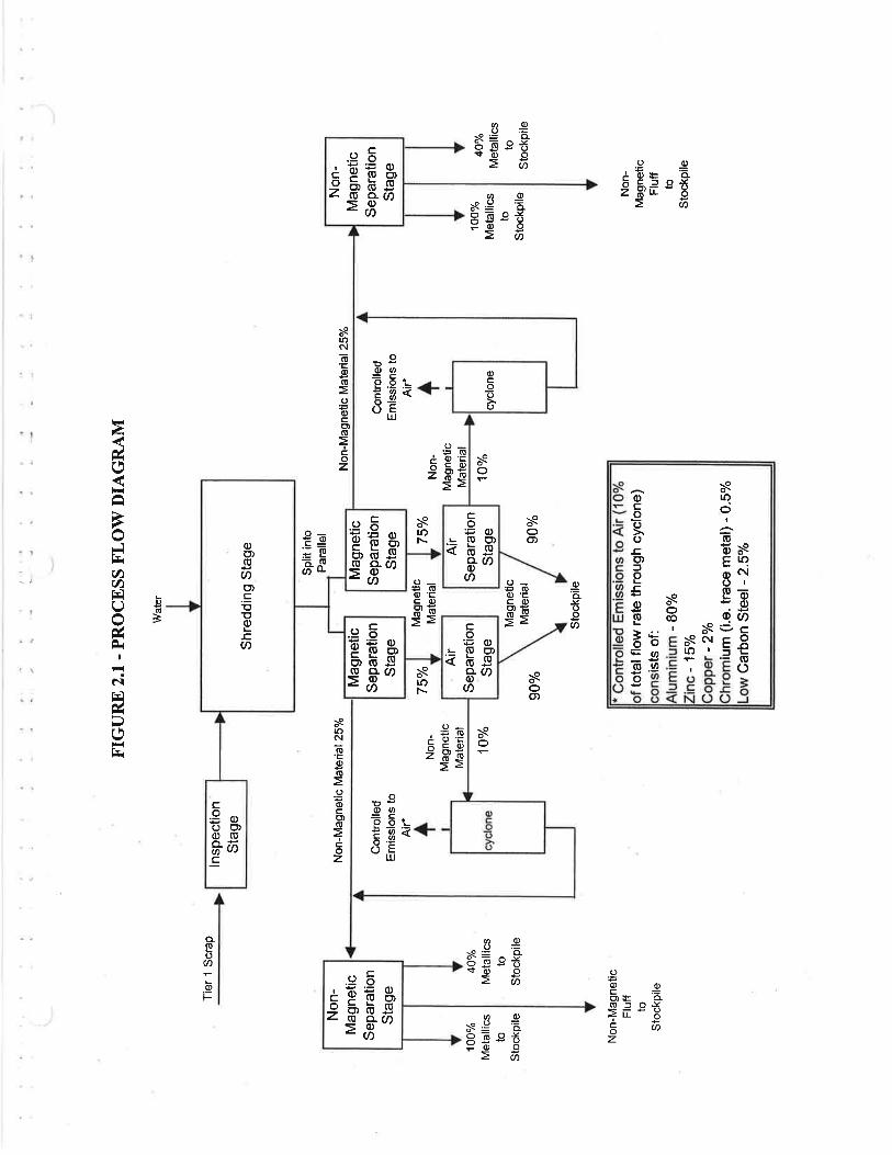
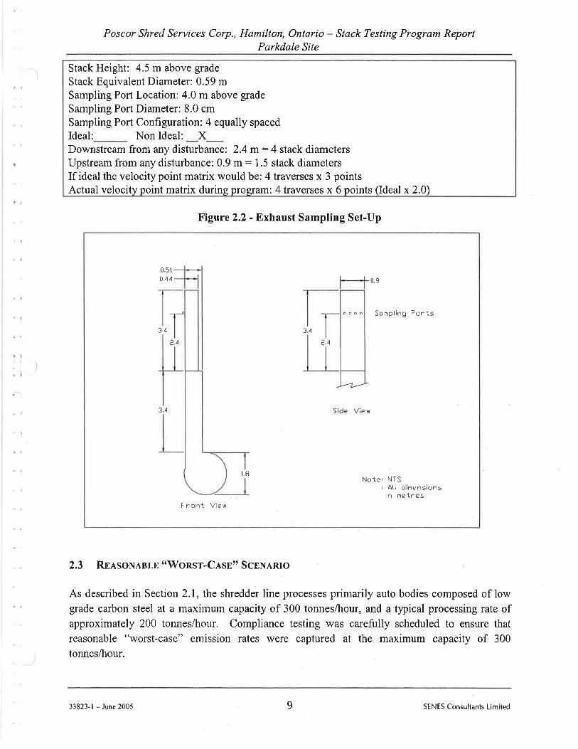
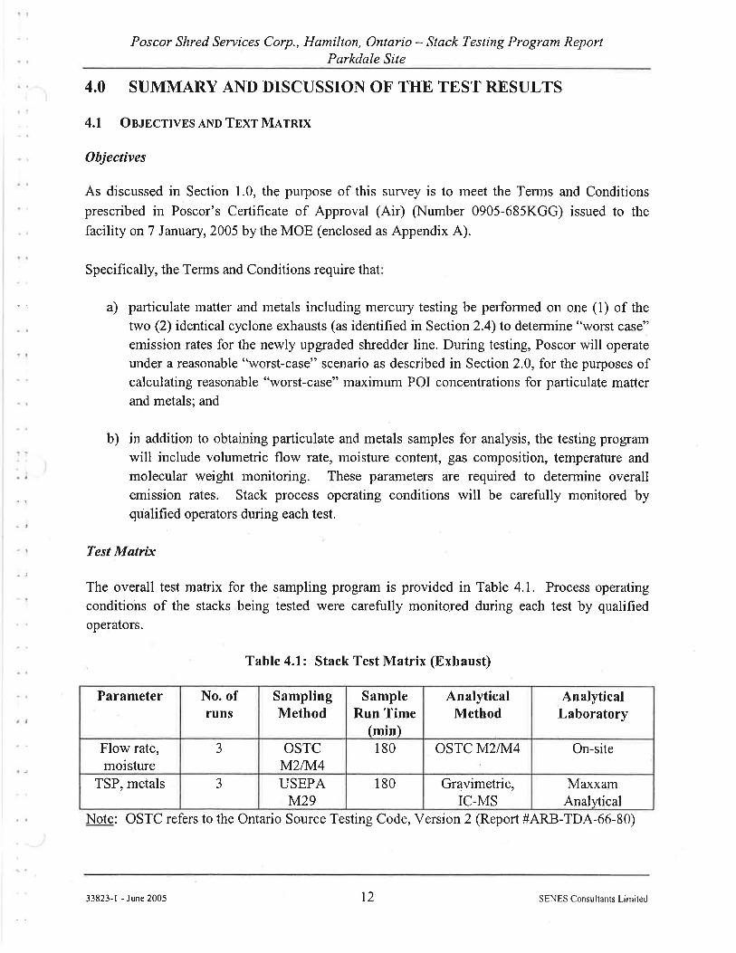
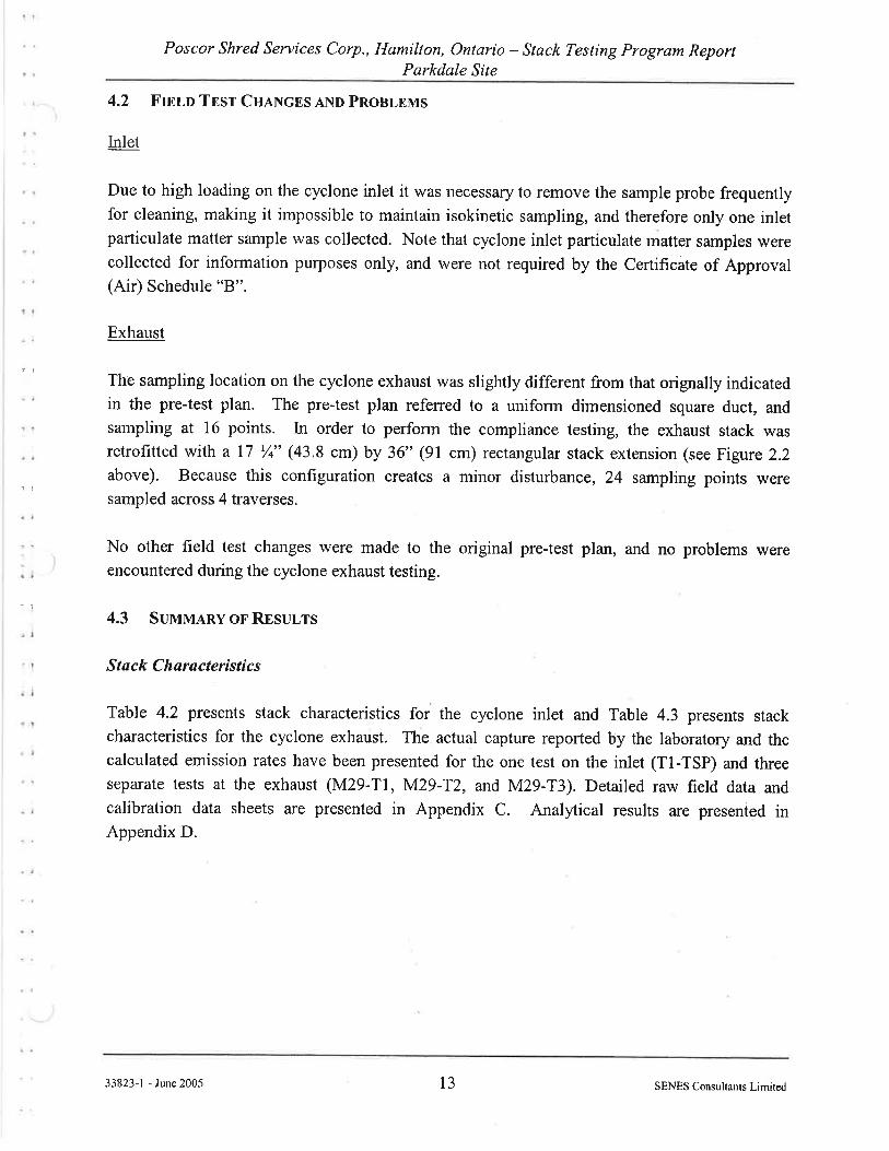
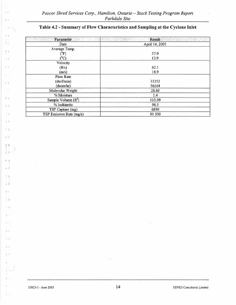
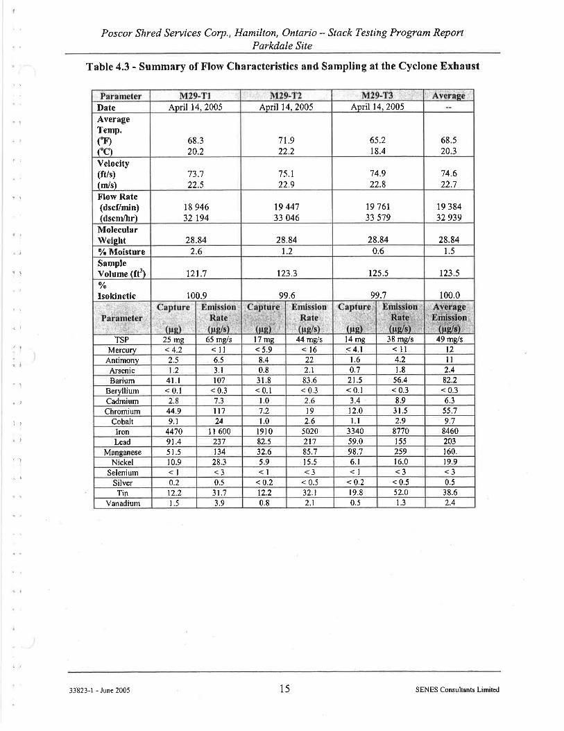
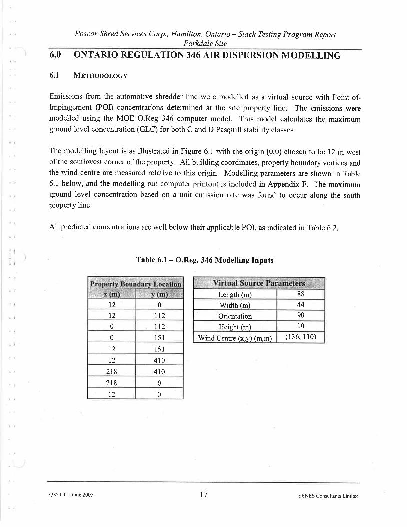
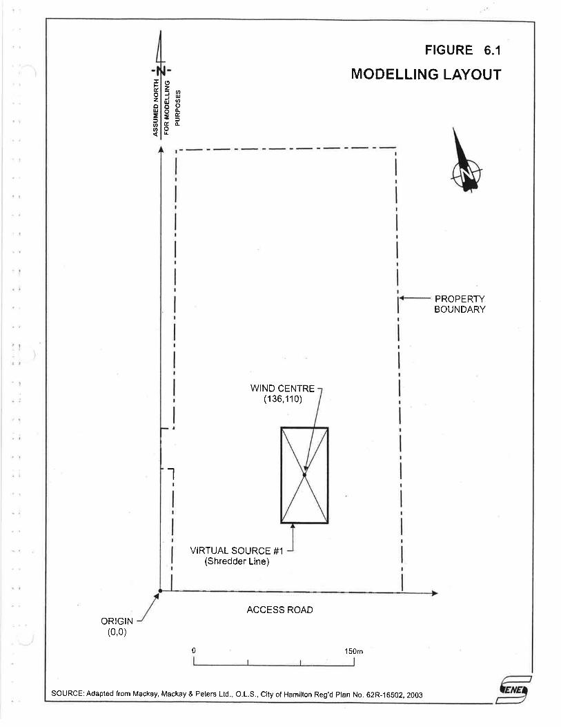
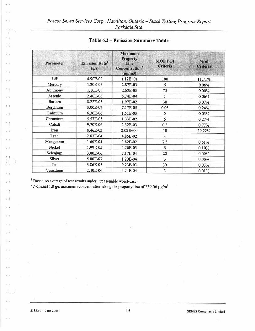
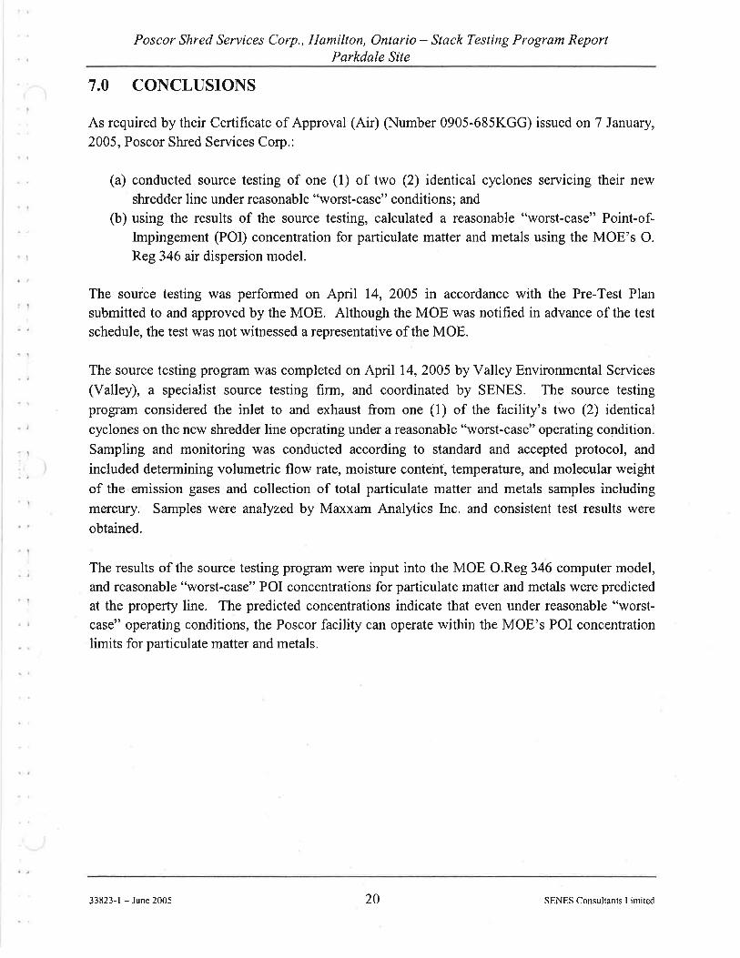
GHD | Emission Summary and Dispersion Modelling Report | 11201621 (2)
Appendix F Oxy-Propane January 2011 Source Test Report
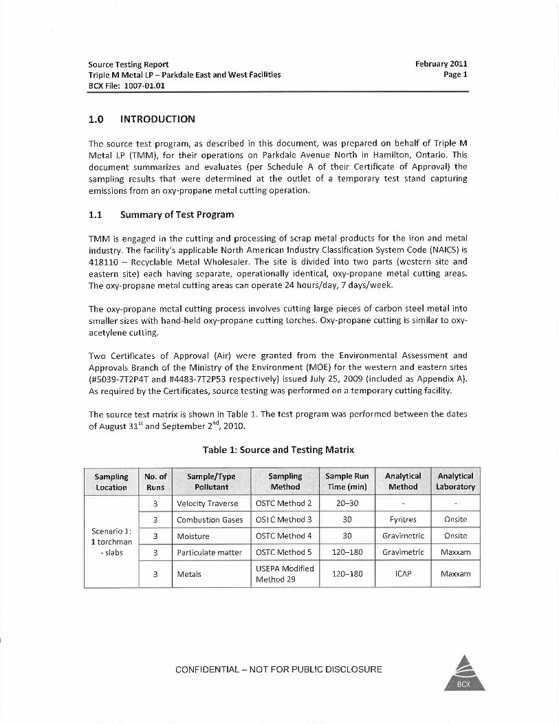

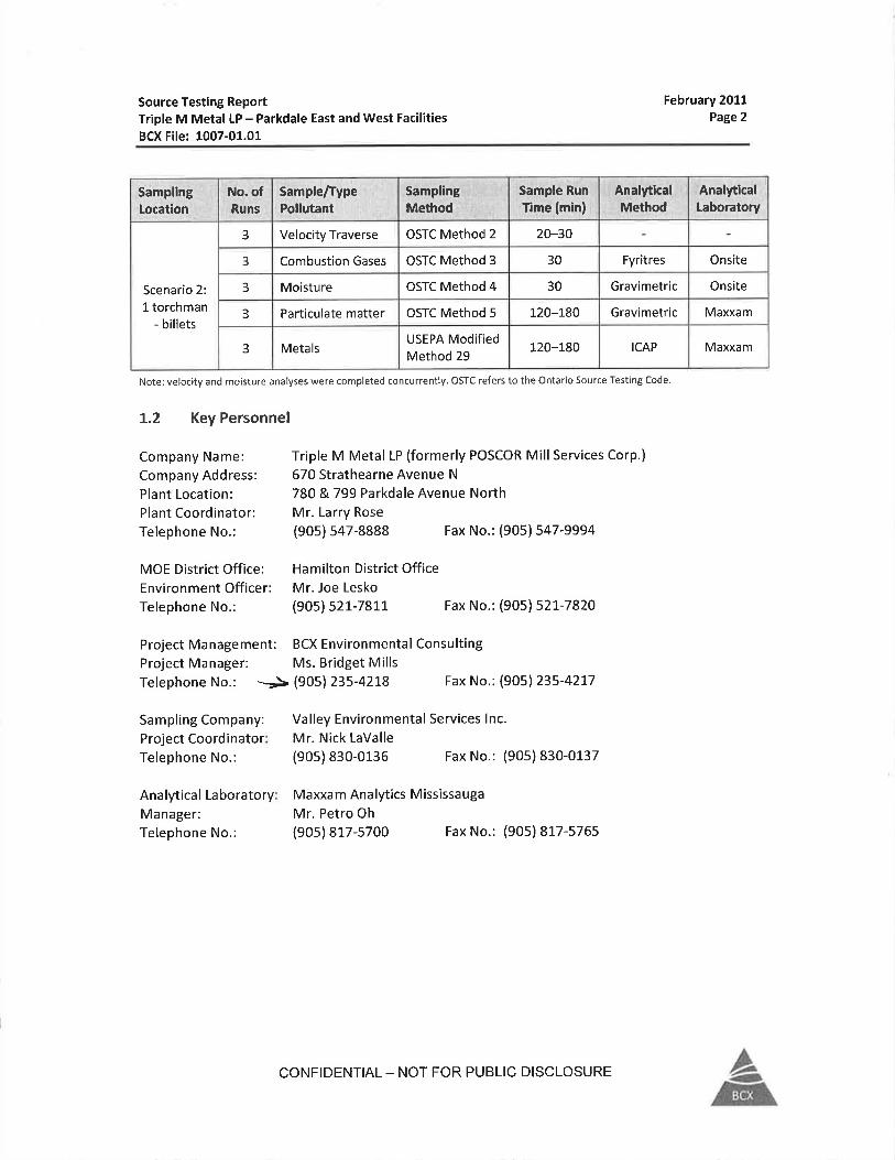
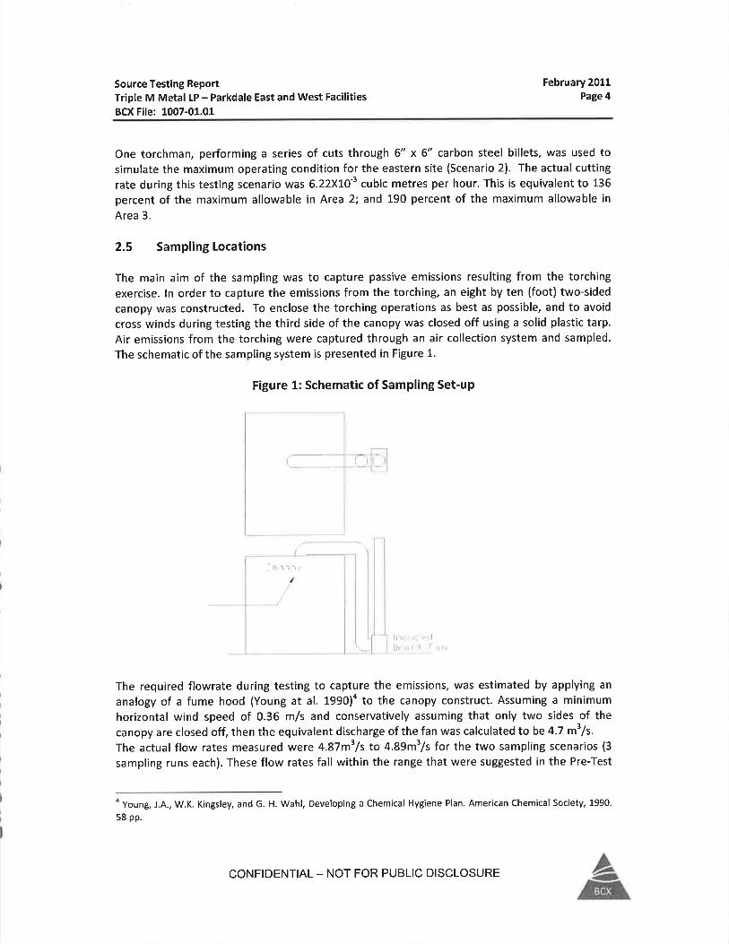
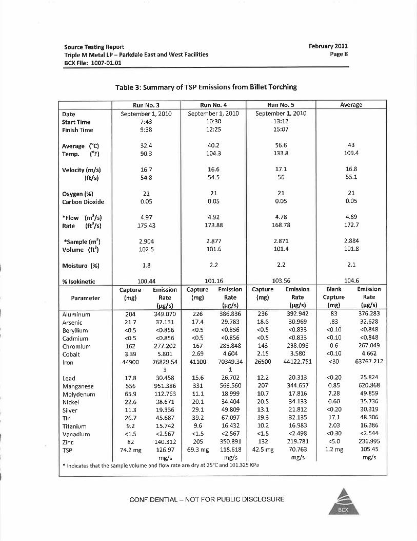
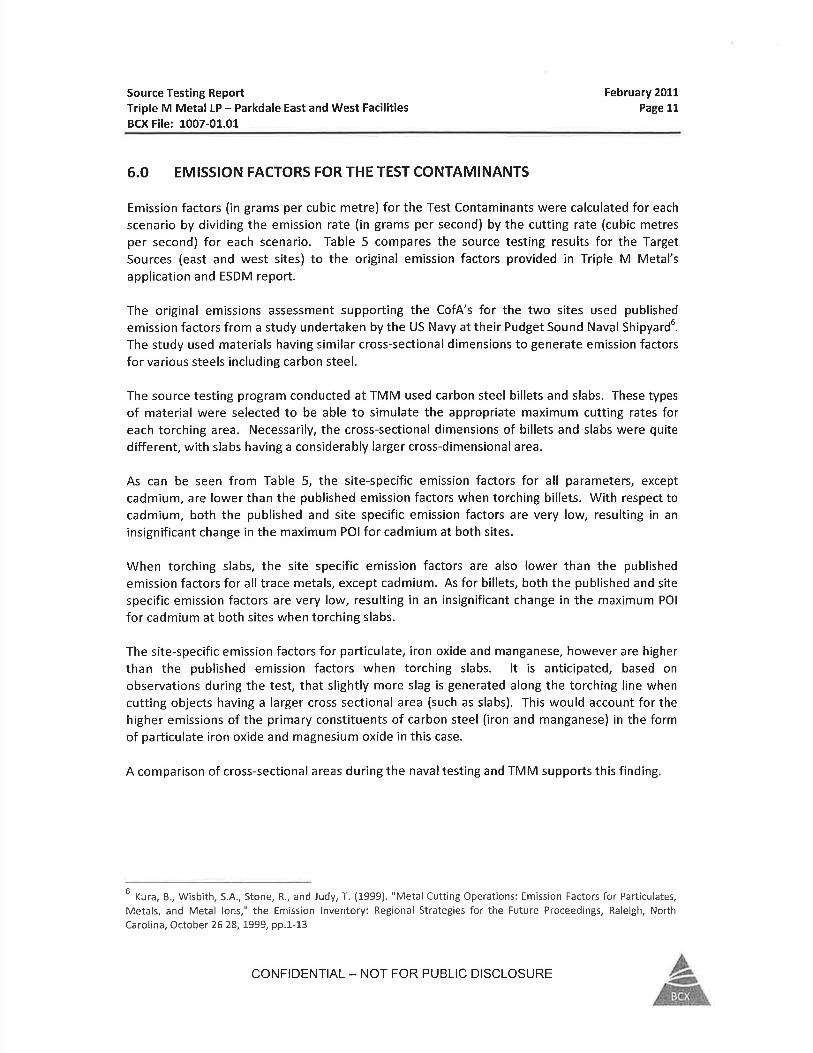
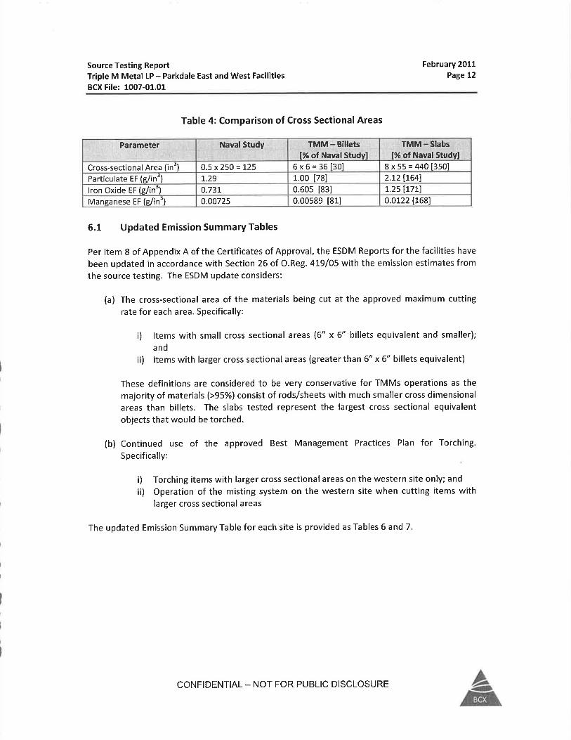
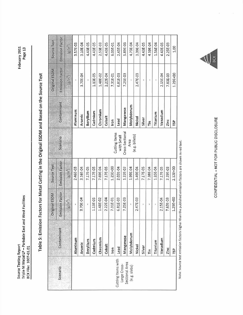
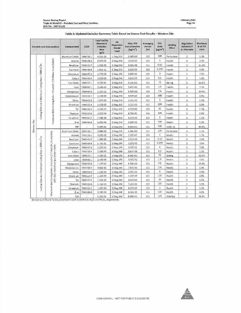
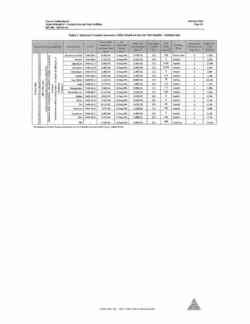
GHD | Emission Summary and Dispersion Modelling Report | 11201621 (2)
Appendix G Safety Data Sheets for Welding
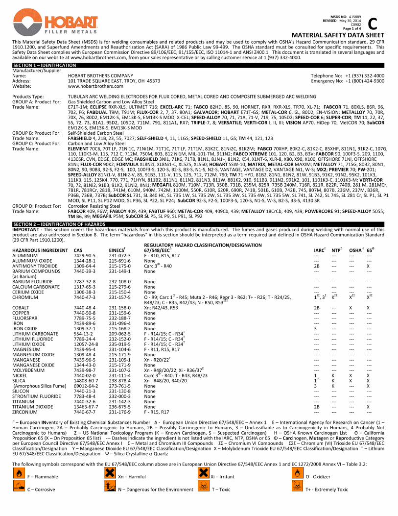
C
MSDS NO: 415889
REVISED: May 30, 2014 C0902 Page 1 of 4
MATERIAL SAFETY DATA SHEET
This Material Safety Data Sheet (MSDS) is for welding consumables and related products and may be used to comply with OSHA's Hazard Communication standard, 29 CFR 1910.1200, and Superfund Amendments and Reauthorization Act (SARA) of 1986 Public Law 99‐499. The OSHA standard must be consulted for specific requirements. This Safety Data Sheet complies with European Commission Directive 89/106/EEC, 91/155/EEC, ISO 11014‐1 and ANSI Z400.1. This document is translated in several languages and available on our website at www.hobartbrothers.com, from your sales representative or by calling customer service at 1 (937) 332‐4000. SECTION 1 – IDENTIFICATION Manufacturer/Supplier Name: HOBART BROTHERS COMPANY Telephone No: +1 (937) 332‐4000 Address: 101 TRADE SQUARE EAST, TROY, OH 45373 Emergency No: +1 (800) 424‐9300 Website: www.hobartbrothers.com
Products Type: TUBULAR ARC WELDING ELECTRODES FOR FLUX CORED, METAL CORED AND COMPOSITE SUBMERGED ARC WELDING GROUP A: Product For: Gas Shielded Carbon and Low Alloy Steel Trade Name: E71T‐1M; ECLIPSE RXR‐XLS, ULTIMET 716; EXCEL‐ARC 71; FABCO 82HD, 85, 90, HORNET, RXR, RXR‐XLS, TR70, XL‐71; FABCOR 71, 80XLS, 86R, 96,
702, F6; FABDUAL T9M, T91M; FLUX‐COR 2, 7, 37, 80A1; GALVACOR; HOBART E71T‐GS; METAL‐COR 6, 6L, 80D2, EN‐VISION; METALLOY 70, 70R, 70X, 76, 80D2, EM12K‐S, EM13K‐S, EM13K‐S MOD, X‐CEL; SPEED‐ALLOY 70, 71, 71A, 71‐V, 719, 75, 105D2; SPEED‐COR 6; SUPER‐COR; TM 11, 22, 37, 55, 72, 73, 81A1, 95D2, 105D2, 711M, 791, 811A1, RX7; TRIPLE‐7, 8; VERSATILE; VERTI‐COR I, II, III; VISION AP70, HiDep 70, MetCOR 70; SubCOR EM12K‐S, EM13K‐S, EM13K‐S MOD
GROUP B: Product For: Self‐Shielded Carbon Steel Trade Name: FABSHIELD 4, 21B, 23, 55, 7027; SELF‐SHIELD 4, 11, 11GS; SPEED‐SHIELD 11, GS; TM 44, 121, 123 GROUP C: Product For: Carbon and Low Alloy Steel Trade Name: ELEMENT 70C6, 70T LF, 71Ni1C, 71Ni1M, 71T1C, 71T LF, 71T1M, 81K2C, 81Ni2C, 81K2M; FABCO 70XHP, 80K2‐C, 81K2‐C, 85XHP, 811N1, 91K2‐C, 107G,
110, 110K3‐M, 115, 712 C, 712M, 750M, 803, 812 Ni1M, MIL‐101‐TM, 911N2; FABCO XTREME 101, 120, B2, B3, B3V; FABCOR 90, 100F3‐S, 209, 1100, 4130SR, CVN, EDGE, EDGE MC; FABSHIELD 3Ni1, 71K6, 71T8, 81N1, 81N1+, 81N2, K54, XLNT‐6, XLR‐8, X80, X90, X100, OFFSHORE 71Ni, OFFSHORE 81Ni; FLUX‐COR 90K2; FORMULA XL8Ni1, XL8Ni1‐C, XL525, XL550; HOBART SSW‐10; MATRIX; METAL‐COR MAXIM; METALLOY 71, 71SG, 80B2, 80N1, 80N2, 90, 90B3, 92‐S, F2‐S, 100, 100F3‐S, 120‐S, B2‐S, B3‐S, N1‐S, N2‐S, VANTAGE, VANTAGE D2, VANTAGE Ni1, W‐S; MX2; PREMIER 70; PW‐201; SPEED‐ALLOY 81Ni1‐V, 81Ni2‐V, 85, 91B3, 111‐V, 115, 125, 712, 712M, 790; TM 71 HYD, 81B2, 81N1, 81N2, 81W, 91B3, 91K2, 91N2, 95K2, 101K3, 111K3, 115, 125K4, 770, 771, 71HYN, 811B2, 811N1, 811N2, 811N3, 811W, 881K2, 910, 911B3, 911N2, 991K2, 101, 1101K3‐C, 1101K3‐M; VERTI‐COR 70, 72, 81Ni2, 91B3, 91K2, 91Ni2, IINi1; MEGAFIL 810M, 710M, 713R, 350B, 731B, 235M, 825R, 735B 240M, 716R, 821R, 822R, 740B, 281 M, 281MCr, 781R, 781RCr, 281B, 741M, 610M, 940M, 742M, 1100M, 550R, 610R, 620R, 690R, 741B, 501B, 610B, 742B, 745, 807M, 807B, 236M, 237M, 836R, P36B, 736B, 737B; SubCOR SL 731, SL 840 HC, SL 735 1W, SL 735 2W, SL 735 3W, SL 735 4W, SL 735 5W, SL 741, SL 742, SL 745, SL 281 Cr, SL P1, SL P1 MOD, SL P11, SL P12 MOD, SL P36, SL P22, SL P24; SubCOR 92‐S, F2‐S, 100F3‐S, 120‐S, N1‐S, W‐S, B2‐S, B3‐S, 4130 SR
GROUP D: Product For: Corrosion Resisting Steel Trade Name: FABCOR 409, F6W; FABLOY 409, 439; FABTUF 960; METAL‐COR 409, 409Cb, 439; METALLOY 18CrCb, 409, 439; POWERCORE 91; SPEED‐ALLOY 5055;
TM B6, B9; MEGAFIL P5M; SubCOR SL P5, SL P9, SL P91, SL P92 SECTION 2 – IDENTIFICATION OF HAZARDS IMPORTANT ‐ This section covers the hazardous materials from which this product is manufactured. The fumes and gases produced during welding with normal use of this product are also addressed in Section 8. The term "hazardous" in this section should be interpreted as a term required and defined in OSHA Hazard Communication Standard (29 CFR Part 1910.1200). REGULATORY HAZARD CLASSIFICATION/DESIGNATION HAZARDOUS INGREDIENT CAS EINECS
Γ 67/548/EEC
Δ IARC
Ε NTP
Ζ OSHA
Η 65
Θ
ALUMINUM 7429‐90‐5 231‐072‐3 F ‐ R10, R15, R17 ‐‐‐ ‐‐‐ ‐‐‐ ‐‐‐ ALUMINUM OXIDE 1344‐28‐1 215‐691‐6 None ‐‐‐ ‐‐‐ ‐‐‐ ‐‐‐ANTIMONY TRIOXIDE 1309‐64‐4 215‐175‐0 Carc 3
Φ ‐ R40 2B ‐‐‐ ‐‐‐ X
BARIUM COMPOUNDS 7440‐39‐3 231‐149‐1 None ‐‐‐ ‐‐‐ ‐‐‐ ‐‐‐ (as Barium) BARIUM FLOURIDE 7787‐32‐8 232‐108‐0 None ‐‐‐ ‐‐‐ ‐‐‐ ‐‐‐ CALCIUM CARBONATE 1317‐65‐3 215‐279‐6 None ‐‐‐ ‐‐‐ ‐‐‐ ‐‐‐ CERIUM OXIDE 1306‐38‐3 215‐150‐4 None ‐‐‐ ‐‐‐ ‐‐‐ ‐‐‐ CHROMIUM 7440‐47‐3 231‐157‐5 O ‐ R9; Carc 1
Φ ‐ R45; Muta 2 ‐ R46; Repr 3 ‐ R62; T+ ‐ R26; T ‐ R24/25, 1
ΣΣ, 3
Σ K
ΣΣ X
ΣΣ X
ΣΣ
R48/23; C ‐ R35, R42/43; N ‐ R50, R53ΣΣΣ
COBALT 7440‐48‐4 231‐158‐0 Xn; R42/43, R53 2B ‐‐‐ X X COPPER 7440‐50‐8 231‐159‐6 None ‐‐‐ ‐‐‐ ‐‐‐ ‐‐‐FLUORSPAR 7789‐75‐5 232‐188‐7 None ‐‐‐ ‐‐‐ ‐‐‐ ‐‐‐ IRON 7439‐89‐6 231‐096‐4 None ‐‐‐ ‐‐‐ ‐‐‐ ‐‐‐ IRON OXIDE 1309‐37‐1 215‐168‐2 None 3 ‐‐‐ ‐‐‐ ‐‐‐ LITHIUM CARBONATE 554‐13‐2 209‐062‐5 F ‐ R14/15; C ‐ R34
Τ ‐‐‐ ‐‐‐ ‐‐‐ ‐‐‐
LITHIUM FLUORIDE 7789‐24‐4 232‐152‐0 F ‐ R14/15; C ‐ R34Τ ‐‐‐ ‐‐‐ ‐‐‐ ‐‐‐
LITHIUM OXIDE 12057‐24‐8 235‐019‐5 F ‐ R14/15; C ‐ R34Τ ‐‐‐ ‐‐‐ ‐‐‐ ‐‐‐
MAGNESIUM 7439‐95‐4 231‐104‐6 F ‐ R11, R15, R17 ‐‐‐ ‐‐‐ ‐‐‐ ‐‐‐ MAGNESIUM OXIDE 1309‐48‐4 215‐171‐9 None ‐‐‐ ‐‐‐ ‐‐‐ ‐‐‐ MANGANESE 7439‐96‐5 231‐105‐1 Xn ‐ R20/22
Y ‐‐‐ ‐‐‐ ‐‐‐ ‐‐‐
MANGANESE OXIDE 1344‐43‐0 215‐171‐9 None ‐‐‐ ‐‐‐ ‐‐‐ ‐‐‐ MOLYBDENUM 7439‐98‐7 231‐107‐2 Xn ‐ R48/20/22; Xi ‐ R36/37
Χ ‐‐‐ ‐‐‐ ‐‐‐ ‐‐‐
NICKEL 7440‐02‐0 231‐111‐4 Crc 3Φ ‐ R40; T ‐ R43, R48/23 1 K X X SILICA 14808‐60‐7 238‐878‐4 Xn ‐ R48/20, R40/20 1
Ψ K X X
(Amorphous Silica Fume) 69012‐64‐2 273‐761‐5 None 3 K ‐‐‐ X SILICON 7440‐21‐3 231‐130‐8 None ‐‐‐ ‐‐‐ ‐‐‐ ‐‐‐ STRONTIUM FLUORIDE 7783‐48‐4 232‐000‐3 None ‐‐‐ ‐‐‐ ‐‐‐ ‐‐‐ TITANIUM 7440‐32‐6 231‐142‐3 None ‐‐‐ ‐‐‐ ‐‐‐ ‐‐‐ TITANIUM DIOXIDE 13463‐67‐7 236‐675‐5 None 2B ‐‐‐ ‐‐‐ X ZIRCONIUM 7440‐67‐7 231‐176‐9 F ‐ R15, R17 ‐‐‐ ‐‐‐ ‐‐‐ ‐‐‐ Γ – European INventory of Existing Chemical Substances Number Δ ‐ European Union Directive 67/548/EEC – Annex 1 Ε – International Agency for Research on Cancer (1 – Human Carcinogen, 2A – Probably Carcinogenic to Humans, 2B – Possibly Carcinogenic to Humans, 3 – Unclassifiable as to Carcinogenicity in Humans, 4 Probably Not Carcinogenic to Humans) Ζ – US National Toxicology Program (K – Known Carcinogen, S – Suspected Carcinogen) Η – OSHA Known Carcinogen List Θ – California Proposition 65 (X – On Proposition 65 list) ‐‐‐ Dashes indicate the ingredient is not listed with the IARC, NTP, OSHA or 65 Φ – Carcinogen, Mutagen or Reproductive Category per European Council Directive 67/548/EEC Annex I Σ – Metal and Chromium III Compounds ΣΣ – Chromium VI Compounds ΣΣΣ – Chromium (VI) Trioxide EU 67/548/EEC Classification/Designation Y – Manganese Dioxide EU 67/548/EEC Classification/Designation X – Molybdenum Trioxide EU 67/548/EEC Classification/Designation Τ – Lithium EU 67/548/EEC Classification/Designation Ψ – Silica Crystalline α‐Quartz The following symbols correspond with the EU 67/548/EEC column above are in European Union Directive 67/548/EEC Annex 1 and EC 1272/2008 Annex VI – Table 3.2:
F – Flammable Xn – Harmful Xi – Irritant O ‐ Oxidizer
C – Corrosive N – Dangerous for the Environment T – Toxic T+ ‐ Extremely Toxic
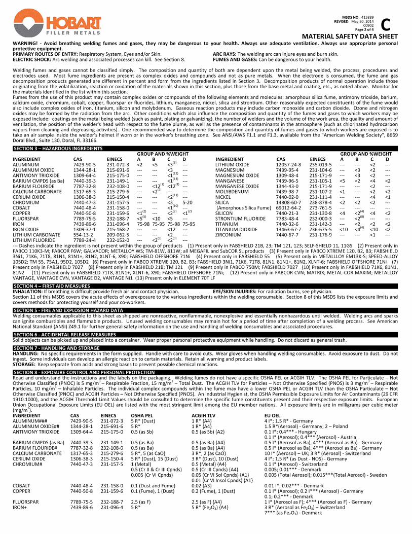
C
MSDS NO: 415889
REVISED: May 30, 2014 C0902 Page 2 of 4
MATERIAL SAFETY DATA SHEET
WARNING! ‐ Avoid breathing welding fumes and gases, they may be dangerous to your health. Always use adequate ventilation. Always use appropriate personal protective equipment. PRIMARY ROUTES OF ENTRY: Respiratory System, Eyes and/or Skin. ARC RAYS: The welding arc can injure eyes and burn skin. ELECTRIC SHOCK: Arc welding and associated processes can kill. See Section 8. FUMES AND GASES: Can be dangerous to your health. Welding fumes and gases cannot be classified simply. The composition and quantity of both are dependent upon the metal being welded, the process, procedures and electrodes used. Most fume ingredients are present as complex oxides and compounds and not as pure metals. When the electrode is consumed, the fume and gas decomposition products generated are different in percent and form from the ingredients listed in Section 3. Decomposition products of normal operation include those originating from the volatilization, reaction or oxidation of the materials shown in this section, plus those from the base metal and coating, etc., as noted above. Monitor for the materials identified in the list within this section. Fumes from the use of this product may contain complex oxides or compounds of the following elements and molecules: amorphous silica fume, antimony trioxide, barium, calcium oxide, chromium, cobalt, copper, fluorspar or fluorides, lithium, manganese, nickel, silica and strontium. Other reasonably expected constituents of the fume would also include complex oxides of iron, titanium, silicon and molybdenum. Gaseous reaction products may include carbon monoxide and carbon dioxide. Ozone and nitrogen oxides may be formed by the radiation from the arc. Other conditions which also influence the composition and quantity of the fumes and gases to which workers may be exposed include: coatings on the metal being welded (such as paint, plating or galvanizing), the number of welders and the volume of the work area, the quality and amount of ventilation, the position of the welder's head with respect to the fume plume, as well as the presence of contaminants in the atmosphere (such as chlorinated hydrocarbon vapors from cleaning and degreasing activities). One recommended way to determine the composition and quantity of fumes and gases to which workers are exposed is to take an air sample inside the welder's helmet if worn or in the worker's breathing zone. See ANSI/AWS F1.1 and F1.3, available from the "American Welding Society", 8669 Doral Blvd., Suite 130, Doral, FL 33166. SECTION 3 – HAZARDOUS INGREDIENTS GROUP AND %WEIGHT GROUP AND %WEIGHT INGREDIENT CAS EINECS A B C D INGREDIENT CAS EINECS A B C D ALUMINUM 7429‐90‐5 231‐072‐3 <2 <5 <3
(6) ‐‐‐
ALUMINUM OXIDE 1344‐28‐1 215‐691‐6 ‐‐‐ ‐‐‐ <3 ‐‐‐ ANTIMONY TRIOXIDE 1309‐64‐4 215‐175‐0 ‐‐‐ ‐‐‐ <1
(12) ‐‐‐
BARIUM CMPDS (as Ba) 7440‐39‐3 231‐149‐1 ‐‐‐ ‐‐‐ <1(13)
‐‐‐ BARIUM FLOURIDE 7787‐32‐8 232‐108‐0 ‐‐‐ <12
(1) <12
(3) ‐‐‐
CALCIUM CARBONATE 1317‐65‐3 215‐279‐6 ‐‐‐ <2(7) ‐‐‐ ‐‐‐
CERIUM OXIDE 1306‐38‐3 215‐150‐4 ‐‐‐ ‐‐‐ <2(11)
‐‐‐ CHROMIUM 7440‐47‐3 231‐157‐5 ‐‐‐ ‐‐‐ <3 5‐20 COBALT 7440‐48‐4 231‐158‐0 ‐‐‐ ‐‐‐ <1
(10) ‐‐‐
COPPER 7440‐50‐8 231‐159‐6 <1(2) ‐‐‐ <2
(2) <1
(2)
FLUORSPAR 7789‐75‐5 232‐188‐7 <5(5) <10 <5 ‐‐‐
IRON 7439‐89‐6 231‐096‐4 75‐98 75‐95 75‐98 75‐95 IRON OXIDE 1309‐37‐1 215‐168‐2 ‐‐‐ ‐‐‐ <12 ‐‐‐ LITHIUM CARBONATE 554‐13‐2 209‐062‐5 ‐‐‐ ‐‐‐ <2 ‐‐‐ LITHIUM FLUORIDE 7789‐24‐4 232‐152‐0 ‐‐‐ <2
(9) <2
(9) ‐‐‐
LITHIUM OXIDE 12057‐24‐8 235‐019‐5 ‐‐‐ ‐‐‐ <2 ‐‐‐ MAGNESIUM 7439‐95‐4 231‐104‐6 ‐‐‐ <3 <2 ‐‐‐ MAGNESIUM OXIDE 1309‐48‐4 215‐171‐9 ‐‐‐ <3 <2 ‐‐‐ MANGANESE 7439‐96‐5 231‐105‐1 <5 <2 <4 <2 MANGANESE OXIDE 1344‐43‐0 215‐171‐9 ‐‐‐ ‐‐‐ <2 ‐‐‐ MOLYBDENUM 7439‐98‐7 231‐107‐2 <1 ‐‐‐ <2 <2 NICKEL 7440‐02‐0 231‐111‐4 ‐‐‐ ‐‐‐ <4 <1 SILICA 14808‐60‐7 238‐878‐4 <2 <2 <2 ‐‐‐
(Amorphous Silica Fume) 69012‐64‐2 273‐761‐5 ‐‐‐ ‐‐‐ ‐‐‐ ‐‐‐ SILICON 7440‐21‐3 231‐130‐8 <4 <2
(4) <4 <2
STRONTIUM FLUORIDE 7783‐48‐4 232‐000‐3 ‐‐‐ <2(8) ‐‐‐ ‐‐‐
TITANIUM 7440‐32‐6 231‐142‐3 ‐‐‐ <2 <2 <2 TITANIUM DIOXIDE 13463‐67‐7 236‐675‐5 <10 <4
(4) <10 <2
ZIRCONIUM 7440‐67‐7 231‐176‐9 ‐‐‐ ‐‐‐ <1 ‐‐‐
‐‐‐ Dashes indicate the ingredient is not present within the group of products (1) Present only in FABSHIELD 21B, 23; TM 121, 123; SELF‐SHIELD 11, 11GS (2) Present only in FABCO 110K3‐M; FABCOR F6W; GALVACOR; METALLOY WS; TM‐81W, 811W; all MEGAFIL and SubCOR SL products (3) Present only in FABCO XTREME 120, B2, B3; FABSHIELD 3Ni1, 71K6, 71T8, 81N1, 81N1+, 81N2, XLNT‐6, X90; FABSHIELD OFFSHORE 71Ni (4) Present only in FABSHIELD 55 (5) Present only in METALLLOY EM13K‐S; SPEED‐ALLOY 105D2; TM 55, 75A1, 95D2, 105D2 (6) Present only in FABCO XTREME 120, B2, B3; FABSHIELD 3Ni1, 71K6, 71T8, 81N1, 81N1+, 81N2, XLNT‐6; FABSHIELD OFFSHORE 71Ni (7) Present only in FABSHIELD 7027 (8) Present only in FABSHIELD 21B; TM 121 (9) Present only in FABCO 750M; FABSHIELD 7027 (10) Present only in FABSHIELD 71K6, 81N1, 81N2 (11) Present only in FABSHIELD 71T8, 81N1+, XLNT‐6, X90; FABSHIELD OFFSHORE 71Ni; (12) Present only in FABCOR CVN; MATRIX; METAL‐COR MAXIM; METALLOY VANTAGE, VANTAGE CVN, VANTAGE D2, VANTAGE Ni1 (13) Present only in ELEMENT 70T LF SECTION 4 – FIRST AID MEASURES INHALATION: If breathing is difficult provide fresh air and contact physician. EYE/SKIN INJURIES: For radiation burns, see physician. Section 11 of this MSDS covers the acute effects of overexposure to the various ingredients within the welding consumable. Section 8 of this MSDS lists the exposure limits and covers methods for protecting yourself and your co‐workers. SECTION 5 ‐ FIRE AND EXPLOSION HAZARD DATA Welding consumables applicable to this sheet as shipped are nonreactive, nonflammable, nonexplosive and essentially nonhazardous until welded. Welding arcs and sparks can ignite combustibles and flammable products. Unused welding consumables may remain hot for a period of time after completion of a welding process. See American National Standard (ANSI) Z49.1 for further general safety information on the use and handling of welding consumables and associated procedures. SECTION 6 ‐ ACCIDENTAL RELEASE MEASURES Solid objects can be picked up and placed into a container. Wear proper personal protective equipment while handling. Do not discard as general trash. SECTION 7 ‐ HANDLING AND STORAGE HANDLING: No specific requirements in the form supplied. Handle with care to avoid cuts. Wear gloves when handling welding consumables. Avoid exposure to dust. Do not ingest. Some individuals can develop an allergic reaction to certain materials. Retain all warning and product labels. STORAGE: Keep separate from acids and strong bases to prevent possible chemical reactions. SECTION 8 ‐ EXPOSURE CONTROL AND PERSONAL PROTECTION Read and understand the instructions and the labels on the packaging. Welding fumes do not have a specific OSHA PEL or ACGIH TLV. The OSHA PEL for Particulate – Not Otherwise Classified (PNOC) is 5 mg/m
3 – Respirable Fraction, 15 mg/m
3 – Total Dust. The ACGIH TLV for Particles – Not Otherwise Specified (PNOS) is 3 mg/m
3 – Respirable
Particles, 10 mg/m3 – Inhalable Particles. The individual complex compounds within the fume may have a lower OSHA PEL or ACGIH TLV than the OSHA Particulate – Not
Otherwise Classified (PNOC) and ACGIH Particles – Not Otherwise Specified (PNOS). An Industrial Hygienist, the OSHA Permissible Exposure Limits for Air Contaminants (29 CFR 1910.1000), and the ACGIH Threshold Limit Values should be consulted to determine the specific fume constituents present and their respective exposure limits. European Union Occupational Exposure Limits (EU OEL) are listed with the most stringent limit among the EU member nations. All exposure limits are in milligrams per cubic meter (mg/m
3).
INGREDIENT CAS EINECS OSHA PEL ACGIH TLV EU OEL ALUMINUM### 7429‐90‐5 231‐072‐3 5 R* (Dust) 1 R* {A4} 4 I*; 1.5 R* ‐ Germany ALUMINUM OXIDE## 1344‐28‐1 215‐691‐6 5 R* 1 R* {A4} 1.5 R*(Aerosol) ‐ Germany; 2 – Poland ANTIMONY TRIOXIDE 1309‐64‐4 215‐175‐0 0.5 (as Sb) 0.5 (as Sb) {A2} 0.1 I*; 0.4*** ‐ Hungary 0.1 I* (Aerosol); 0.4*** (Aerosol) ‐ Austria BARIUM CMPDS (as Ba) 7440‐39‐3 231‐149‐1 0.5 (as Ba) 0.5 (as Ba) {A4} 0.5 I* (Aerosol as Ba), 4*** (Aerosol as Ba) ‐ Germany BARIUM FLOURIDE# 7787‐32‐8 232‐108‐0 0.5 (as Ba) 0.5 (as Ba) {A4} 0.5 I* (Aerosol as Ba), 4*** (Aerosol as Ba) ‐ Germany CALCIUM CARBONATE 1317‐65‐3 215‐279‐6 5 R*, 5 (as CaO) 3 R*, 2 (as CaO) 10 I* (Aerosol) – UK; 3 R* (Aerosol) ‐ Switzerland CERIUM OXIDE 1306‐38‐3 215‐150‐4 5 R* (Dust), 15 (Dust) 3 R* (Dust), 10 (Dust) 4 I*; 1.5 R* (as Dust ‐ NOS) ‐ Germany CHROMIUM# 7440‐47‐3 231‐157‐5 1 (Metal) 0.5 (Metal) {A4} 0.1 I* (Aerosol) ‐ Switzerland 0.5 (Cr II & Cr III Cpnds) 0.5 (Cr III Cpnds) {A4} 0.005; 0.01*** ‐ Denmark 0.005 (Cr VI Cpnds) 0.05 (Cr VI Sol Cpnds) {A1} 0.005 (Total Aerosol); 0.015***(Total Aerosol) ‐ Sweden 0.01 (Cr VI Insol Cpnds) {A1} COBALT 7440‐48‐4 231‐158‐0 0.1 (Dust and Fume) 0.02 {A3} 0.01 I*; 0.02*** ‐ Denmark COPPER 7440‐50‐8 231‐159‐6 0.1 (Fume), 1 (Dust) 0.2 (Fume), 1 (Dust) 0.1 I* (Aerosol); 0.2 I*** (Aerosol) ‐ Germany 0.1; 0.2*** ‐ Denmark FLUORSPAR 7789‐75‐5 232‐188‐7 2.5 (as F) 2.5 (as F) {A4} 1 I* (Aerosol as F); 4*** (Aerosol as F) ‐ Germany IRON+ 7439‐89‐6 231‐096‐4 5 R* 5 R* (Fe2O3) {A4} 3 R* (Aerosol as Fe2O3) – Switzerland 7*** (as Fe2O3) ‐ Denmark
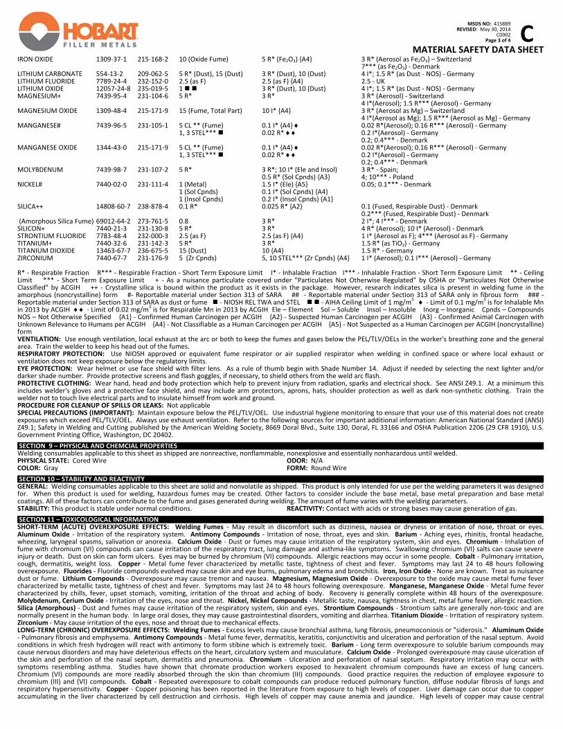
C
MSDS NO: 415889
REVISED: May 30, 2014 C0902 Page 3 of 4
MATERIAL SAFETY DATA SHEET
IRON OXIDE 1309‐37‐1 215‐168‐2 10 (Oxide Fume) 5 R* (Fe2O3) {A4} 3 R* (Aerosol as Fe2O3) – Switzerland 7*** (as Fe2O3) ‐ Denmark LITHIUM CARBONATE 554‐13‐2 209‐062‐5 5 R* (Dust), 15 (Dust) 3 R* (Dust), 10 (Dust) 4 I*; 1.5 R* (as Dust ‐ NOS) ‐ Germany LITHIUM FLUORIDE 7789‐24‐4 232‐152‐0 2.5 (as F) 2.5 (as F) {A4} 2.5 ‐ UK LITHIUM OXIDE 12057‐24‐8 235‐019‐5 1 3 R* (Dust), 10 (Dust) 4 I*; 1.5 R* (as Dust ‐ NOS) ‐ Germany MAGNESIUM+ 7439‐95‐4 231‐104‐6 5 R* 3 R* 3 R* (Aerosol) ‐ Switzerland 4 I*(Aerosol); 1.5 R*** (Aerosol) ‐ Germany MAGNESIUM OXIDE 1309‐48‐4 215‐171‐9 15 (Fume, Total Part) 10 I* {A4} 3 R* (Aerosol as Mg) – Switzerland 4 I*(Aerosol as Mg); 1.5 R*** (Aerosol as Mg) ‐ Germany MANGANESE# 7439‐96‐5 231‐105‐1 5 CL ** (Fume) 0.1 I* {A4} 0.02 R*(Aerosol); 0.16 R*** (Aerosol) ‐ Germany 1, 3 STEL*** 0.02 R* 0.2 I*(Aerosol) ‐ Germany 0.2; 0.4*** ‐ Denmark MANGANESE OXIDE 1344‐43‐0 215‐171‐9 5 CL ** (Fume) 0.1 I* {A4} 0.02 R*(Aerosol); 0.16 R*** (Aerosol) ‐ Germany 1, 3 STEL*** 0.02 R* 0.2 I*(Aerosol) ‐ Germany 0.2; 0.4*** ‐ Denmark MOLYBDENUM 7439‐98‐7 231‐107‐2 5 R* 3 R*; 10 I* (Ele and Insol) 3 R* ‐ Spain; 0.5 R* (Sol Cpnds) {A3} 4; 10*** ‐ Poland NICKEL# 7440‐02‐0 231‐111‐4 1 (Metal) 1.5 I* (Ele) {A5} 0.05; 0.1*** ‐ Denmark 1 (Sol Cpnds) 0.1 I* (Sol Cpnds) {A4} 1 (Insol Cpnds) 0.2 I* (Insol Cpnds) {A1} SILICA++ 14808‐60‐7 238‐878‐4 0.1 R* 0.025 R* {A2} 0.1 (Fused, Respirable Dust) ‐ Denmark 0.2*** (Fused, Respirable Dust) ‐ Denmark (Amorphous Silica Fume) 69012‐64‐2 273‐761‐5 0.8 3 R* 2 I*; 4 I*** ‐ Denmark SILICON+ 7440‐21‐3 231‐130‐8 5 R* 3 R* 4 R* (Aerosol); 10 I* (Aerosol) ‐ Denmark STRONTIUM FLUORIDE 7783‐48‐4 232‐000‐3 2.5 (as F) 2.5 (as F) {A4} 1 I* (Aerosol as F); 4*** (Aerosol as F) ‐ Germany TITANIUM+ 7440‐32‐6 231‐142‐3 5 R* 3 R* 1.5 R* (as TiO2) ‐ Germany TITANIUM DIOXIDE 13463‐67‐7 236‐675‐5 15 (Dust) 10 {A4} 1.5 R* ‐ Germany ZIRCONIUM 7440‐67‐7 231‐176‐9 5 (Zr Cpnds) 5, 10 STEL*** (Zr Cpnds) {A4} 1 I* (Aerosol); 0.1 I*** (Aerosol) ‐ Germany R* ‐ Respirable Fraction R*** ‐ Respirable Fraction ‐ Short Term Exposure Limit I* ‐ Inhalable Fraction I*** ‐ Inhalable Fraction ‐ Short Term Exposure Limit ** ‐ Ceiling Limit *** ‐ Short Term Exposure Limit + ‐ As a nuisance particulate covered under "Particulates Not Otherwise Regulated" by OSHA or "Particulates Not Otherwise Classified" by ACGIH ++ ‐ Crystalline silica is bound within the product as it exists in the package. However, research indicates silica is present in welding fume in the amorphous (noncrystalline) form #‐ Reportable material under Section 313 of SARA ## ‐ Reportable material under Section 313 of SARA only in fibrous form ### ‐ Reportable material under Section 313 of SARA as dust or fume ‐ NIOSH REL TWA and STEL ‐ AIHA Ceiling Limit of 1 mg/m
3 ‐ Limit of 0.1 mg/m
3 is for Inhalable Mn
in 2013 by ACGIH ‐ Limit of 0.02 mg/m3 is for Respirable Mn in 2013 by ACGIH Ele – Element Sol – Soluble Insol – Insoluble Inorg – Inorganic Cpnds – Compounds
NOS – Not Otherwise Specified {A1} ‐ Confirmed Human Carcinogen per ACGIH {A2} ‐ Suspected Human Carcinogen per ACGIH {A3} ‐ Confirmed Animal Carcinogen with Unknown Relevance to Humans per ACGIH {A4} ‐ Not Classifiable as a Human Carcinogen per ACGIH {A5} ‐ Not Suspected as a Human Carcinogen per ACGIH (noncrystalline) form VENTILATION: Use enough ventilation, local exhaust at the arc or both to keep the fumes and gases below the PEL/TLV/OELs in the worker's breathing zone and the general area. Train the welder to keep his head out of the fumes. RESPIRATORY PROTECTION: Use NIOSH approved or equivalent fume respirator or air supplied respirator when welding in confined space or where local exhaust or ventilation does not keep exposure below the regulatory limits. EYE PROTECTION: Wear helmet or use face shield with filter lens. As a rule of thumb begin with Shade Number 14. Adjust if needed by selecting the next lighter and/or darker shade number. Provide protective screens and flash goggles, if necessary, to shield others from the weld arc flash. PROTECTIVE CLOTHING: Wear hand, head and body protection which help to prevent injury from radiation, sparks and electrical shock. See ANSI Z49.1. At a minimum this includes welder's gloves and a protective face shield, and may include arm protectors, aprons, hats, shoulder protection as well as dark non‐synthetic clothing. Train the welder not to touch live electrical parts and to insulate himself from work and ground. PROCEDURE FOR CLEANUP OF SPILLS OR LEAKS: Not applicable SPECIAL PRECAUTIONS (IMPORTANT): Maintain exposure below the PEL/TLV/OEL. Use industrial hygiene monitoring to ensure that your use of this material does not create exposures which exceed PEL/TLV/OEL. Always use exhaust ventilation. Refer to the following sources for important additional information: American National Standard (ANSI) Z49.1; Safety in Welding and Cutting published by the American Welding Society, 8669 Doral Blvd., Suite 130, Doral, FL 33166 and OSHA Publication 2206 (29 CFR 1910), U.S. Government Printing Office, Washington, DC 20402. SECTION 9 – PHYSICAL AND CHEMCIAL PROPERTIES Welding consumables applicable to this sheet as shipped are nonreactive, nonflammable, nonexplosive and essentially nonhazardous until welded. PHYSICAL STATE: Cored Wire ODOR: N/A COLOR: Gray FORM: Round Wire SECTION 10 – STABILITY AND REACTIVITY GENERAL: Welding consumables applicable to this sheet are solid and nonvolatile as shipped. This product is only intended for use per the welding parameters it was designed for. When this product is used for welding, hazardous fumes may be created. Other factors to consider include the base metal, base metal preparation and base metal coatings. All of these factors can contribute to the fume and gases generated during welding. The amount of fume varies with the welding parameters. STABILITY: This product is stable under normal conditions. REACTIVITY: Contact with acids or strong bases may cause generation of gas. SECTION 11 – TOXICOLOGICAL INFORMATION SHORT‐TERM (ACUTE) OVEREXPOSURE EFFECTS: Welding Fumes ‐ May result in discomfort such as dizziness, nausea or dryness or irritation of nose, throat or eyes. Aluminum Oxide ‐ Irritation of the respiratory system. Antimony Compounds ‐ Irritation of nose, throat, eyes and skin. Barium ‐ Aching eyes, rhinitis, frontal headache, wheezing, laryngeal spasms, salivation or anorexia. Calcium Oxide ‐ Dust or fumes may cause irritation of the respiratory system, skin and eyes. Chromium ‐ Inhalation of fume with chromium (VI) compounds can cause irritation of the respiratory tract, lung damage and asthma‐like symptoms. Swallowing chromium (VI) salts can cause severe injury or death. Dust on skin can form ulcers. Eyes may be burned by chromium (VI) compounds. Allergic reactions may occur in some people. Cobalt ‐ Pulmonary irritation, cough, dermatitis, weight loss. Copper ‐ Metal fume fever characterized by metallic taste, tightness of chest and fever. Symptoms may last 24 to 48 hours following overexposure. Fluorides ‐ Fluoride compounds evolved may cause skin and eye burns, pulmonary edema and bronchitis. Iron, Iron Oxide ‐ None are known. Treat as nuisance dust or fume. Lithium Compounds ‐ Overexposure may cause tremor and nausea. Magnesium, Magnesium Oxide ‐ Overexposure to the oxide may cause metal fume fever characterized by metallic taste, tightness of chest and fever. Symptoms may last 24 to 48 hours following overexposure. Manganese, Manganese Oxide ‐ Metal fume fever characterized by chills, fever, upset stomach, vomiting, irritation of the throat and aching of body. Recovery is generally complete within 48 hours of the overexposure. Molybdenum, Cerium Oxide ‐ Irritation of the eyes, nose and throat. Nickel, Nickel Compounds ‐ Metallic taste, nausea, tightness in chest, metal fume fever, allergic reaction. Silica (Amorphous) ‐ Dust and fumes may cause irritation of the respiratory system, skin and eyes. Strontium Compounds ‐ Strontium salts are generally non‐toxic and are normally present in the human body. In large oral doses, they may cause gastrointestinal disorders, vomiting and diarrhea. Titanium Dioxide ‐ Irritation of respiratory system. Zirconium ‐ May cause irritation of the eyes, nose and throat due to mechanical effects. LONG‐TERM (CHRONIC) OVEREXPOSURE EFFECTS: Welding Fumes ‐ Excess levels may cause bronchial asthma, lung fibrosis, pneumoconiosis or "siderosis." Aluminum Oxide ‐ Pulmonary fibrosis and emphysema. Antimony Compounds ‐ Metal fume fever, dermatitis, keratitis, conjunctivitis and ulceration and perforation of the nasal septum. Avoid conditions in which fresh hydrogen will react with antimony to form stibine which is extremely toxic. Barium ‐ Long term overexposure to soluble barium compounds may cause nervous disorders and may have deleterious effects on the heart, circulatory system and musculature. Calcium Oxide ‐ Prolonged overexposure may cause ulceration of the skin and perforation of the nasal septum, dermatitis and pneumonia. Chromium ‐ Ulceration and perforation of nasal septum. Respiratory irritation may occur with symptoms resembling asthma. Studies have shown that chromate production workers exposed to hexavalent chromium compounds have an excess of lung cancers. Chromium (VI) compounds are more readily absorbed through the skin than chromium (III) compounds. Good practice requires the reduction of employee exposure to chromium (III) and (VI) compounds. Cobalt ‐ Repeated overexposure to cobalt compounds can produce reduced pulmonary function, diffuse nodular fibrosis of lungs and respiratory hypersensitivity. Copper ‐ Copper poisoning has been reported in the literature from exposure to high levels of copper. Liver damage can occur due to copper accumulating in the liver characterized by cell destruction and cirrhosis. High levels of copper may cause anemia and jaundice. High levels of copper may cause central
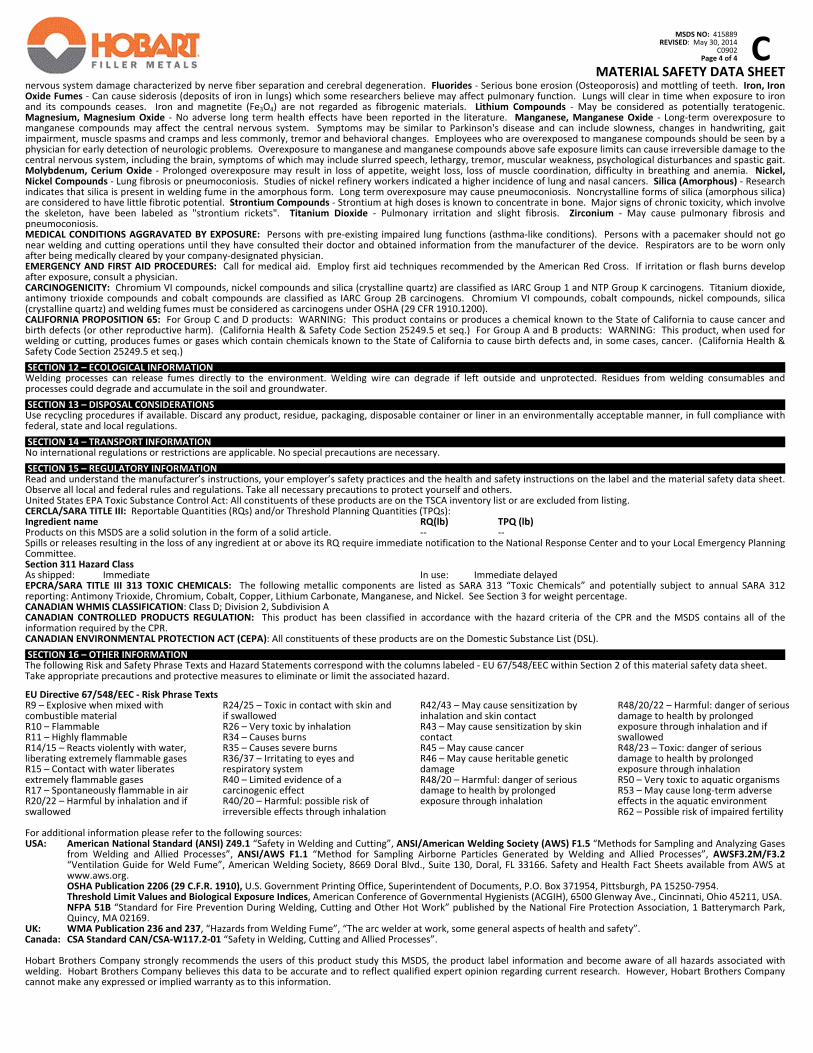
C
MSDS NO: 415889
REVISED: May 30, 2014 C0902 Page 4 of 4
MATERIAL SAFETY DATA SHEET
nervous system damage characterized by nerve fiber separation and cerebral degeneration. Fluorides ‐ Serious bone erosion (Osteoporosis) and mottling of teeth. Iron, Iron Oxide Fumes ‐ Can cause siderosis (deposits of iron in lungs) which some researchers believe may affect pulmonary function. Lungs will clear in time when exposure to iron and its compounds ceases. Iron and magnetite (Fe3O4) are not regarded as fibrogenic materials. Lithium Compounds ‐ May be considered as potentially teratogenic. Magnesium, Magnesium Oxide ‐ No adverse long term health effects have been reported in the literature. Manganese, Manganese Oxide ‐ Long‐term overexposure to manganese compounds may affect the central nervous system. Symptoms may be similar to Parkinson's disease and can include slowness, changes in handwriting, gait impairment, muscle spasms and cramps and less commonly, tremor and behavioral changes. Employees who are overexposed to manganese compounds should be seen by a physician for early detection of neurologic problems. Overexposure to manganese and manganese compounds above safe exposure limits can cause irreversible damage to the central nervous system, including the brain, symptoms of which may include slurred speech, lethargy, tremor, muscular weakness, psychological disturbances and spastic gait. Molybdenum, Cerium Oxide ‐ Prolonged overexposure may result in loss of appetite, weight loss, loss of muscle coordination, difficulty in breathing and anemia. Nickel, Nickel Compounds ‐ Lung fibrosis or pneumoconiosis. Studies of nickel refinery workers indicated a higher incidence of lung and nasal cancers. Silica (Amorphous) ‐ Research indicates that silica is present in welding fume in the amorphous form. Long term overexposure may cause pneumoconiosis. Noncrystalline forms of silica (amorphous silica) are considered to have little fibrotic potential. Strontium Compounds ‐ Strontium at high doses is known to concentrate in bone. Major signs of chronic toxicity, which involve the skeleton, have been labeled as "strontium rickets". Titanium Dioxide ‐ Pulmonary irritation and slight fibrosis. Zirconium ‐ May cause pulmonary fibrosis and pneumoconiosis. MEDICAL CONDITIONS AGGRAVATED BY EXPOSURE: Persons with pre‐existing impaired lung functions (asthma‐like conditions). Persons with a pacemaker should not go near welding and cutting operations until they have consulted their doctor and obtained information from the manufacturer of the device. Respirators are to be worn only after being medically cleared by your company‐designated physician. EMERGENCY AND FIRST AID PROCEDURES: Call for medical aid. Employ first aid techniques recommended by the American Red Cross. If irritation or flash burns develop after exposure, consult a physician. CARCINOGENICITY: Chromium VI compounds, nickel compounds and silica (crystalline quartz) are classified as IARC Group 1 and NTP Group K carcinogens. Titanium dioxide, antimony trioxide compounds and cobalt compounds are classified as IARC Group 2B carcinogens. Chromium VI compounds, cobalt compounds, nickel compounds, silica (crystalline quartz) and welding fumes must be considered as carcinogens under OSHA (29 CFR 1910.1200). CALIFORNIA PROPOSITION 65: For Group C and D products: WARNING: This product contains or produces a chemical known to the State of California to cause cancer and birth defects (or other reproductive harm). (California Health & Safety Code Section 25249.5 et seq.) For Group A and B products: WARNING: This product, when used for welding or cutting, produces fumes or gases which contain chemicals known to the State of California to cause birth defects and, in some cases, cancer. (California Health & Safety Code Section 25249.5 et seq.)
SECTION 12 – ECOLOGICAL INFORMATION Welding processes can release fumes directly to the environment. Welding wire can degrade if left outside and unprotected. Residues from welding consumables and processes could degrade and accumulate in the soil and groundwater. SECTION 13 – DISPOSAL CONSIDERATIONS Use recycling procedures if available. Discard any product, residue, packaging, disposable container or liner in an environmentally acceptable manner, in full compliance with federal, state and local regulations. SECTION 14 – TRANSPORT INFORMATION No international regulations or restrictions are applicable. No special precautions are necessary. SECTION 15 – REGULATORY INFORMATION Read and understand the manufacturer’s instructions, your employer’s safety practices and the health and safety instructions on the label and the material safety data sheet. Observe all local and federal rules and regulations. Take all necessary precautions to protect yourself and others. United States EPA Toxic Substance Control Act: All constituents of these products are on the TSCA inventory list or are excluded from listing. CERCLA/SARA TITLE III: Reportable Quantities (RQs) and/or Threshold Planning Quantities (TPQs): Ingredient name RQ(lb) TPQ (lb) Products on this MSDS are a solid solution in the form of a solid article. ‐‐ ‐‐ Spills or releases resulting in the loss of any ingredient at or above its RQ require immediate notification to the National Response Center and to your Local Emergency Planning Committee. Section 311 Hazard Class As shipped: Immediate In use: Immediate delayed EPCRA/SARA TITLE III 313 TOXIC CHEMICALS: The following metallic components are listed as SARA 313 “Toxic Chemicals” and potentially subject to annual SARA 312 reporting: Antimony Trioxide, Chromium, Cobalt, Copper, Lithium Carbonate, Manganese, and Nickel. See Section 3 for weight percentage. CANADIAN WHMIS CLASSIFICATION: Class D; Division 2, Subdivision A CANADIAN CONTROLLED PRODUCTS REGULATION: This product has been classified in accordance with the hazard criteria of the CPR and the MSDS contains all of the information required by the CPR. CANADIAN ENVIRONMENTAL PROTECTION ACT (CEPA): All constituents of these products are on the Domestic Substance List (DSL). SECTION 16 – OTHER INFORMATION The following Risk and Safety Phrase Texts and Hazard Statements correspond with the columns labeled ‐ EU 67/548/EEC within Section 2 of this material safety data sheet. Take appropriate precautions and protective measures to eliminate or limit the associated hazard.
EU Directive 67/548/EEC ‐ Risk Phrase Texts R9 – Explosive when mixed with combustible material R10 – Flammable R11 – Highly flammable R14/15 – Reacts violently with water, liberating extremely flammable gases R15 – Contact with water liberates extremely flammable gases R17 – Spontaneously flammable in air R20/22 – Harmful by inhalation and if swallowed
R24/25 – Toxic in contact with skin and if swallowed R26 – Very toxic by inhalation R34 – Causes burns R35 – Causes severe burns R36/37 – Irritating to eyes and respiratory system R40 – Limited evidence of a carcinogenic effect R40/20 – Harmful: possible risk of irreversible effects through inhalation
R42/43 – May cause sensitization by inhalation and skin contact R43 – May cause sensitization by skin contact R45 – May cause cancer R46 – May cause heritable genetic damage R48/20 – Harmful: danger of serious damage to health by prolonged exposure through inhalation
R48/20/22 – Harmful: danger of serious damage to health by prolonged exposure through inhalation and if swallowed R48/23 – Toxic: danger of serious damage to health by prolonged exposure through inhalation R50 – Very toxic to aquatic organisms R53 – May cause long‐term adverse effects in the aquatic environment R62 – Possible risk of impaired fertility
For additional information please refer to the following sources: USA: American National Standard (ANSI) Z49.1 “Safety in Welding and Cutting”, ANSI/American Welding Society (AWS) F1.5 “Methods for Sampling and Analyzing Gases
from Welding and Allied Processes”, ANSI/AWS F1.1 “Method for Sampling Airborne Particles Generated by Welding and Allied Processes”, AWSF3.2M/F3.2 “Ventilation Guide for Weld Fume”, American Welding Society, 8669 Doral Blvd., Suite 130, Doral, FL 33166. Safety and Health Fact Sheets available from AWS at www.aws.org.
OSHA Publication 2206 (29 C.F.R. 1910), U.S. Government Printing Office, Superintendent of Documents, P.O. Box 371954, Pittsburgh, PA 15250‐7954. Threshold Limit Values and Biological Exposure Indices, American Conference of Governmental Hygienists (ACGIH), 6500 Glenway Ave., Cincinnati, Ohio 45211, USA.
NFPA 51B “Standard for Fire Prevention During Welding, Cutting and Other Hot Work” published by the National Fire Protection Association, 1 Batterymarch Park, Quincy, MA 02169.
UK: WMA Publication 236 and 237, “Hazards from Welding Fume”, “The arc welder at work, some general aspects of health and safety”. Canada: CSA Standard CAN/CSA‐W117.2‐01 “Safety in Welding, Cutting and Allied Processes”.
Hobart Brothers Company strongly recommends the users of this product study this MSDS, the product label information and become aware of all hazards associated with welding. Hobart Brothers Company believes this data to be accurate and to reflect qualified expert opinion regarding current research. However, Hobart Brothers Company cannot make any expressed or implied warranty as to this information.
SAFETY DATA SHEET CE001 Carbon steel Covered Electrodes
Version number: 1
Replaces SDS: 2009-11-23
Issued: 2014-01-21
1
Not for sale in the USA
Section 1. IDENTIFICATION OF THE SUBSTANCE / MIXTURE AND OF THE COMPANY /
UNDERTAKING
1.1 Product identifier
Trade name Linde Carbon Steel Covered Electrodes
Article-№ .
Product/Article Diameter(mm/Inch) Packaging (kg) Part Number
Linde Electrode E6010IP 4.0 20 11023636
Linde Electrode E6010IP 5.0 20 11023637
Linde Electrode E6011 2.4 16 11023638 Linde Electrode E6011 3.2 20 11023639 Linde Electrode E6011 4.0 20 11023640
Linde Electrode E6013V 2.4 16 11023643 Linde Electrode E6013V 3.2 20 11023644 Linde Electrode E7014IP 2.4 16 11023645 Linde Electrode E7014IP 3.4 20 11023646 Linde Electrode E7024IP 3.2 20 11023665 Linde Electrode E7024IP 4.0 20 11023666 Linde Electrode E7024IP 5.0 20 11023667 Linde Electrode E7018-
1MRP 2.4 16 11023668
Linde Electrode E7018-1MRP
3.2 20 11023669
Linde Electrode E7018-1MRP
4.0 20 11023670
Linde Electrode E7018 MR PLUS
4.8 20 11023671
Linde Electrode E7018 AC 2.4 16 11023682 Linde Electrode E7018 AC 3.2 20 11023684 Linde Electrode 7018AC 3.2 20 11023685
Linde Electrode E7018AC 4.0 20 11023686 Linde Electrode 7018AC 4.0 20 11023687
Linde Electrode 7018 Extra 2.4 16 11101709 Linde Electrode 7018 Extra 3.2 20 11101710 Linde Electrode 7018 Extra 4.0 20 11101711 Linde Electrode 7018 Extra 4.8 20 11101712 Linde Electrode 7018 Extra 6.4 20 11101713 Linde Electrode E7017IP 3.2 20 11183120
Linde Electrode 7018 2.4 16 11183121 Linde Electrode E7024IP 3.2 20 11183124
Linde Electrode 7018 3.2 20 11183122 Linde Electrode 7018AC 3.2 20 11226918
BOC Electrode E7018-1-H4 3/32 4.5 11292813 BOC Electrode E7018-1-H4 1/8 4.5 11292814 BOC Electrode E7018-1-H4 5/32 4.5 11292815
SAFETY DATA SHEET CE001 Carbon steel Covered Electrodes
Version number: 1
Replaces SDS: 2009-11-23
Issued: 2014-01-21
2
Solid Strike Electrode E7018-1H4R
2.5 (3/32) 3.4 11312710
Solid Strike Electrode E7018-1H4R
2.5 (3/32) 4.2 11312711
Solid Strike Electrode E7018-1H4R
3.2(1/8) 4.2 11312712
Solid Strike Electrode E7018-1H4R
4.0 (5/32) 4.6 11312713
Solid Strike Electrode E7018-1H4R
4.0 (5/32) 5.8 11312714
Solid Strike Electrode E7018-1H4R
5.0 (3/16) 5.6 11312715
Solid Strike Electrode E7018-1H4R
6.0 (1/4) 5.8 11312716
1.2 Relevant identified uses of the substance or mixture and uses advised against
Article type SMAW Un- and Low-alloyed electrodes Classification: AWS SFA 5.1/5.5 or other
Use Electric arc welding
1.3 Details of the supplier of the safety data sheet
Supplier Linde Canada Limited
Street address 5860 Chedworth Way, Mississauga
Ontario L5R 0A2
Canada
Telephone 1-866-385-5349
Fax 905-501-1717
Email [email protected]
1.4 Emergency telephone number
Available outside office hours Yes
Emergency phone number (24 Hour) : (905) 501-0802 or CHEMTREC (800) 424-9300
Other
Additional product information Web site: www.lindecanada.com
Section 2. HAZARDS IDENTIFICATION
2.1 Classification of the substance or mixture
Classification according to applicable national regulations.
2.2 Label elements
Refer to label.
2.3 Other hazards
When the product is used in the welding process the most important hazards are:

SAFETY DATA SHEET CE001 Carbon steel Covered Electrodes
Version number: 1
Replaces SDS: 2009-11-23
Issued: 2014-01-21
3
Overexposure to fumes and gases from welding can be dangerous to health. Watch out for splatter, hot metal and slag. It may cause skin burn and cause fire. Arc rays can injure eyes and burn skin. Electric shock can kill. Avoid touching live electrical parts.
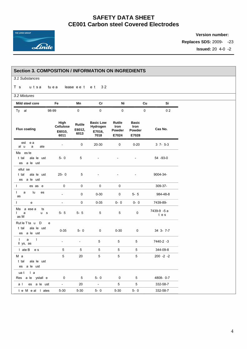
SAFETY DATA SHEET CE001 Carbon steel Covered Electrodes
Version number: 1
Replaces SDS: 2009-11-23
Issued: 2014-01-21
4
Section 3. COMPOSITION / INFORMATION ON INGREDIENTS 3.1 Substances This product is a mixture and please refer to Section 3.2
3.2 Mixtures
Flux coating
High Cellulose
E6010, 6011
Rutile
E6012, 6013
Basic Low Hydrogen
E7016, 7018
Rutile Iron
Powder
E7024
Basic Iron
Powder
E7028
Cas No.
Limestone and/or Calcium Carbonate - <10 20-30 <10 10-20 1317-65-3
Magnesite (total inhalable dust) (respirable dust)
5-10 <5 - - - 546-93-0
Cellulose (total inhalable dust) (respirable dust)
25-60 <15 - - - 9004-34-6
Iron Oxides (as Fe) <10 <10 <10 <10 1309-37-6
Inorganic Fluorides (as F) - <10 10-30 <10 5-15 16984-48-8
Iron powder - <10 10-35 10-60 10-60 7439-89-6
Manganese and its Inorganic compounds (as Mn)
5-15 5-15 <15 <15 <10 7439-96-5 and others
Rutile/Titanium Dioxide (total inhalable dust) (respirable dust)
10-35
15-60
<10
10-30
<10
13463-67-7
Silicon and Silicon Alloys, (as Si) - - <5 <5 <5 7440-21-3
Silicate Binders <5 <5 <5 <5 <5 1344-09-8
Mica (total inhalable dust) (respirable dust)
<5
<20
<5
<5
<5
12001-26-2
Quartz/Silica Respirable crystalline
<10
<15
5-60
<10
<5
14808-60-7
Kaolin (respirable dust) - <20 - <5 <5 1332-58-7
Other Mineral Silicates 5-30 5-30 5-10 5-30 5-10 1332-58-7
Mild steel core Fe Mn Cr Ni Cu Si
Typical 98-99 <0.6 <0.1 <0.1 <0.1 <0.2
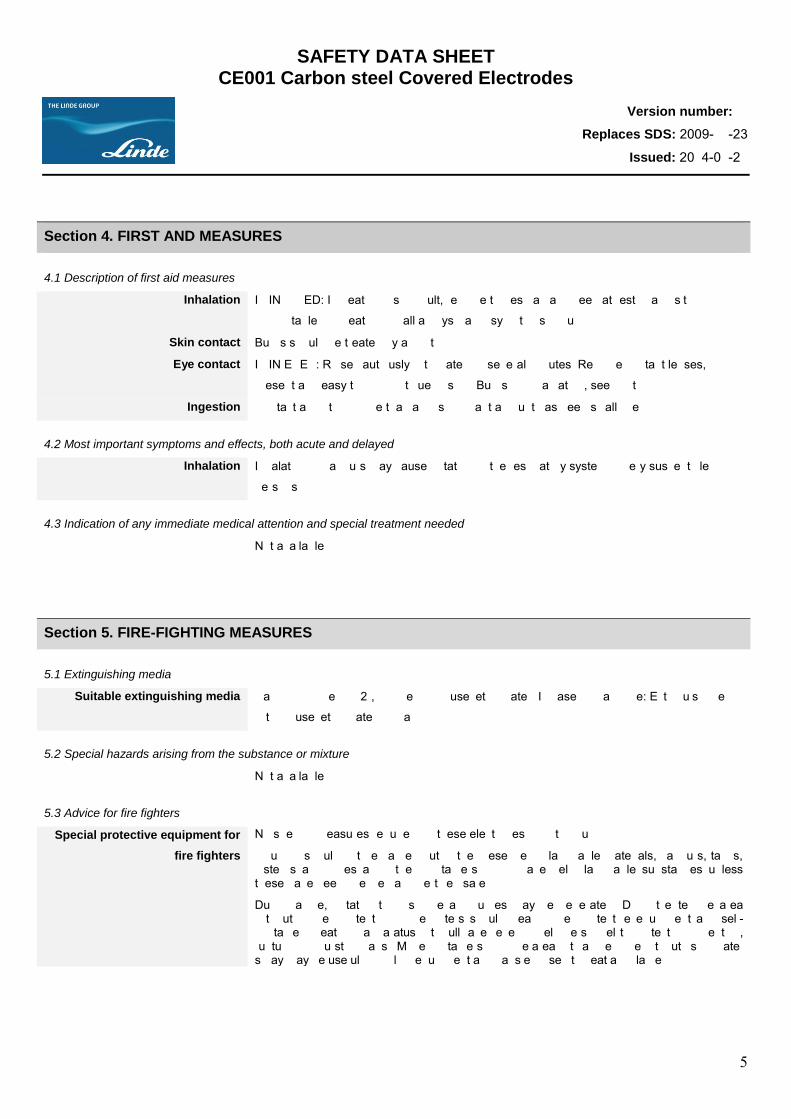
SAFETY DATA SHEET CE001 Carbon steel Covered Electrodes
Version number: 1
Replaces SDS: 2009-11-23
Issued: 2014-01-21
5
Section 4. FIRST AND MEASURES
4.1 Description of first aid measures
Inhalation IF INHALED: If breathing is difficult, remove to fresh air and keep at rest in a position
comfortable for breathing. Call a physician if symptoms occur.
Skin contact Burns should be treated by a doctor.
Eye contact IF IN EYES: Rinse cautiously with water for several minutes. Remove contact lenses, if
present and easy to do. Continue rinsing. Burns from radiation, see doctor.
Ingestion Contact a doctor if more than an insignificant amount has been swallowed.
4.2 Most important symptoms and effects, both acute and delayed
Inhalation Inhalation of vapours may cause irritation of the respiratory system in very susceptible
persons.
4.3 Indication of any immediate medical attention and special treatment needed
Not available
Section 5. FIRE-FIGHTING MEASURES
5.1 Extinguishing media
Suitable extinguishing media Carbon dioxide (CO2), powder or diffuse jet of water. In case of major fire: Extinguish fire
with diffuse jet of water or foam.
5.2 Special hazards arising from the substance or mixture
Not available
5.3 Advice for fire fighters
Special protective equipment for
fire fighters
No specific measures required for these electrodes prior to gouging.
Gouging should not be carried out in the presence of flammable materials, vapours, tanks, cisterns and pipes and other containers which have held flammable substances unless these have been checked and certified safe.
During a fire, irritating/toxic smoke and fumes may be generated. Do not enter fire area without proper protection. Firefighters should wear proper protective equipment and self-contained breathing apparatus with full facepiece. Shield personnel to protect from venting, rupturing or bursting cans. Move containers from fire area if it can be done without risk. Water spray may be useful in cooling equipment and cans exposed to heat and flame.
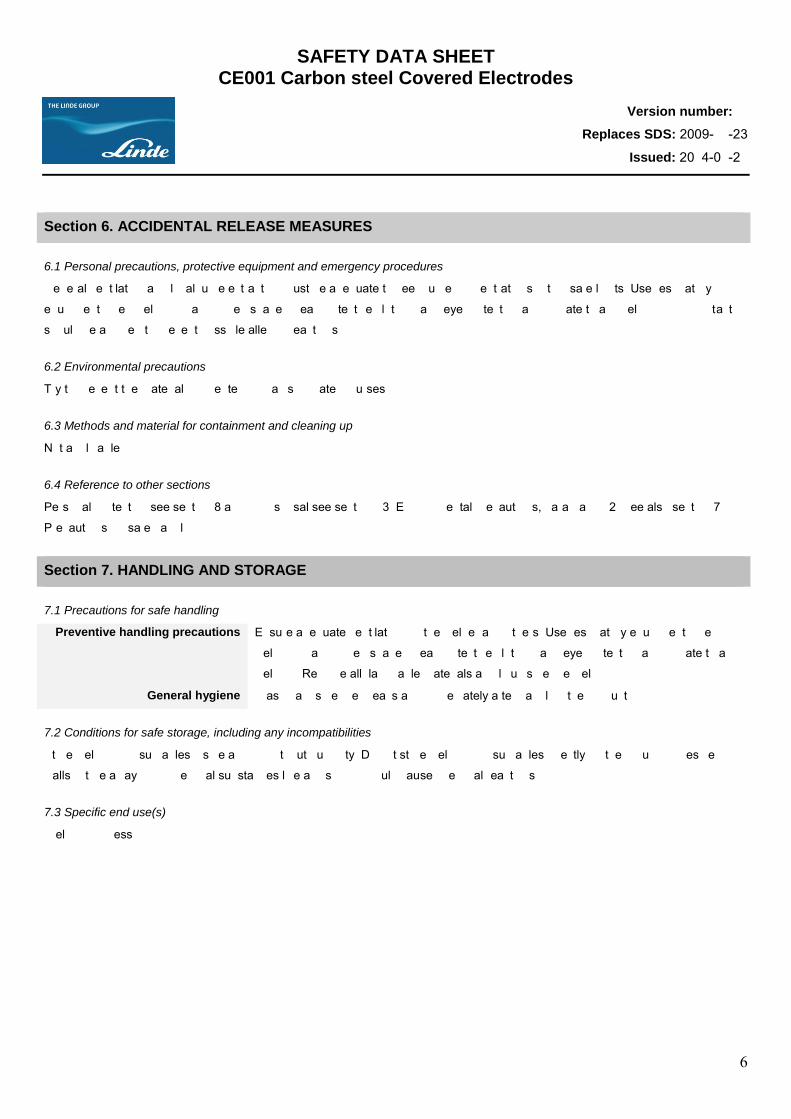
SAFETY DATA SHEET CE001 Carbon steel Covered Electrodes
Version number: 1
Replaces SDS: 2009-11-23
Issued: 2014-01-21
6
Section 6. ACCIDENTAL RELEASE MEASURES
6.1 Personal precautions, protective equipment and emergency procedures
General ventilation and local fume extraction must be adequate to keep fume concentrations within safe limits. Use respiratory
equipment when welding in a confined space. Wear protective clothing and eye protection appropriate to arc welding. Skin contact
should be avoided to prevent possible allergic reactions.
6.2 Environmental precautions
Try to prevent the material from entering drains or water courses.
6.3 Methods and material for containment and cleaning up
Not applicable
6.4 Reference to other sections
Personal protection see section 8 and for disposal see section 13. Environmental precautions, paragraph 12. See also section 7
Precautions for safe handling.
Section 7. HANDLING AND STORAGE
7.1 Precautions for safe handling
Preventive handling precautions Ensure adequate ventilation for the welder and others. Use respiratory equipment when
welding in a confined space. Wear protective clothing and eye protection appropriate to arc
welding. Remove all flammable materials and liquids before welding.
General hygiene Wash hands before breaks and immediately after handling the product.
7.2 Conditions for safe storage, including any incompatibilities
Store welding consumables inside a room without humidity. Do not store welding consumables directly on the ground or beside
walls. Store away from chemical substances like acids which could cause chemical reactions.
7.3 Specific end use(s)
Welding process.
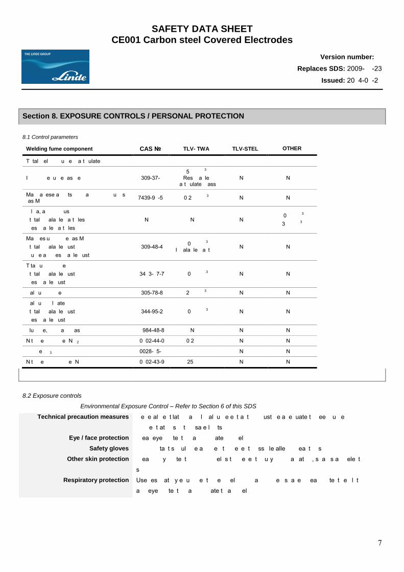
SAFETY DATA SHEET CE001 Carbon steel Covered Electrodes
Version number: 1
Replaces SDS: 2009-11-23
Issued: 2014-01-21
7
Section 8. EXPOSURE CONTROLS / PERSONAL PROTECTION 8.1 Control parameters
Welding fume component CAS № TLV- TWA TLV-STEL OTHER
Total welding fume (particulate)
Iron oxide fume (as Fe) 1309-37-1 5 mg/m3
Respirable particulate mass
N/Av N/Av
Manganese and its inorganic compounds (as Mn) 7439-96-5 0.2 mg/m3 N/Av N/Av
Silica, amorphous (total inhalable particles) (respirable particles)
N/Av N/Av N/Av 10 mg/m3 3 mg/m3
Magnesium oxide (as Mg) (total inhalable dust) (fume and respirable dust)
1309-48-4 10 mg/m3 (Inhalable fraction) N/Av N/Av
Titanium dioxide (total inhalable dust) (respirable dust)
13463-67-7 10 mg/m3 N/Av N/Av
Calcium Oxide 1305-78-8 2 mg/m3 N/Av N/Av
Calcium Silicate (total inhalable dust) (respirable dust)
1344-95-2 10 mg/m3 N/Av N/Av
Fluoride, inorganic (as F) 16984-48-8 N/Av N/Av N/Av
Nitrogen dioxide (NO2) 10102-44-0 0.2 ppm N/Av N/Av
Ozone (O3) 10028-15-6 * N/Av N/Av
Nitrogen monoxide (NO) 10102-43-9 25 ppm N/Av N/Av
8.2 Exposure controls
Environmental Exposure Control – Refer to Section 6 of this SDS
Technical precaution measures General ventilation and local fume extraction must be adequate to keep fume
concentrations within safe limits.
Eye / face protection Wear eye protection appropriate for welding.
Safety gloves Skin contact should be avoided to prevent possible allergic reactions.
Other skin protection Wear body protection which helps to prevent injury from radiation, sparks and electric
shock.
Respiratory protection Use respiratory equipment when welding in a confined space. Wear protective clothing
and eye protection appropriate to arc welding.
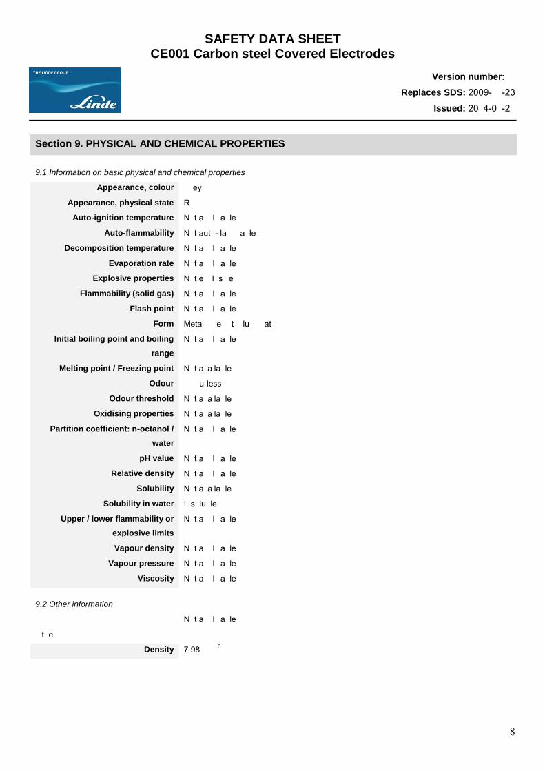
SAFETY DATA SHEET CE001 Carbon steel Covered Electrodes
Version number: 1
Replaces SDS: 2009-11-23
Issued: 2014-01-21
8
Section 9. PHYSICAL AND CHEMICAL PROPERTIES
9.1 Information on basic physical and chemical properties
Appearance, colour Grey
Appearance, physical state Rod
Auto-ignition temperature Not applicable
Auto-flammability Not auto-flammable
Decomposition temperature Not applicable
Evaporation rate Not applicable
Explosive properties Not explosive
Flammability (solid gas) Not applicable
Flash point Not applicable
Form Metal wire with flux coating
Initial boiling point and boiling
range
Not applicable
Melting point / Freezing point Not available
Odour Odourless
Odour threshold Not available
Oxidising properties Not available
Partition coefficient: n-octanol /
water
Not applicable
pH value Not applicable
Relative density Not applicable
Solubility Not available
Solubility in water Insoluble
Upper / lower flammability or
explosive limits
Not applicable
Vapour density Not applicable
Vapour pressure Not applicable
Viscosity Not applicable
9.2 Other information
Not applicable
Other
Density 7.98g/cm3
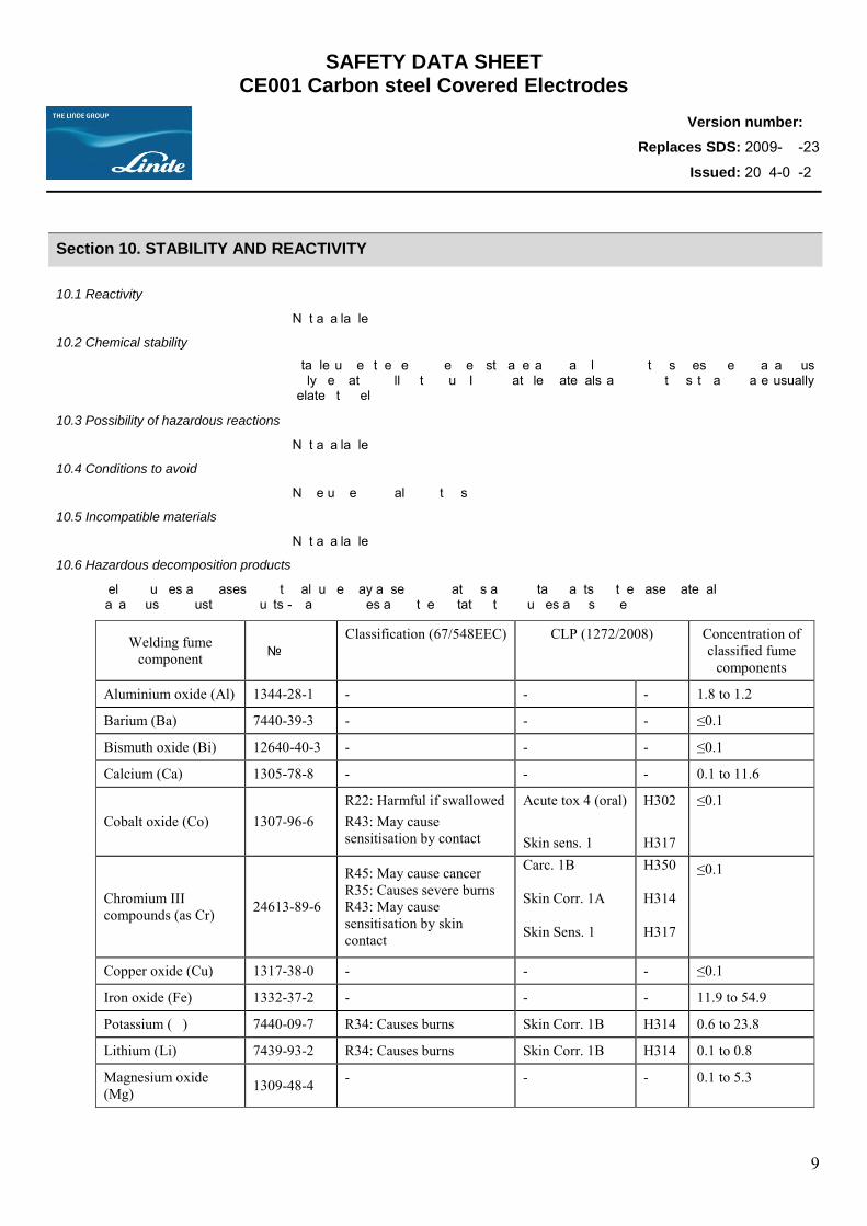
SAFETY DATA SHEET CE001 Carbon steel Covered Electrodes
Version number: 1
Replaces SDS: 2009-11-23
Issued: 2014-01-21
9
Section 10. STABILITY AND REACTIVITY
10.1 Reactivity
Not available
10.2 Chemical stability
Stable under the recommended storage and handling conditions prescribed. Hazardous polymerization will not occur. Incompatible materials and conditions to avoid are usually related to welding.
10.3 Possibility of hazardous reactions
Not available
10.4 Conditions to avoid
None under normal conditions
10.5 Incompatible materials
Not available
10.6 Hazardous decomposition products
Welding fumes and gases. Additional fume may arise from coatings and contaminants on the base material. Hazardous combustion products - Carbon oxides and other irritating/toxic fumes and smoke.
Welding fume component № CAS
Classification (67/548EEC) CLP (1272/2008) Concentration of classified fume
components
Aluminium oxide (Al) 1344-28-1 - - - 1.8 to 1.2
Barium (Ba) 7440-39-3 - - - ≤0.1
Bismuth oxide (Bi) 12640-40-3 - - - ≤0.1
Calcium (Ca) 1305-78-8 - - - 0.1 to 11.6
Cobalt oxide (Co) 1307-96-6 R22: Harmful if swallowed R43: May cause sensitisation by contact
Acute tox 4 (oral) Skin sens. 1
H302 H317
≤0.1
Chromium III compounds (as Cr) 24613-89-6
R45: May cause cancer R35: Causes severe burns R43: May cause sensitisation by skin contact
Carc. 1B Skin Corr. 1A Skin Sens. 1
H350 H314 H317
≤0.1
Copper oxide (Cu) 1317-38-0 - - - ≤0.1
Iron oxide (Fe) 1332-37-2 - - - 11.9 to 54.9
Potassium (K) 7440-09-7 R34: Causes burns Skin Corr. 1B H314 0.6 to 23.8
Lithium (Li) 7439-93-2 R34: Causes burns Skin Corr. 1B H314 0.1 to 0.8
Magnesium oxide (Mg) 1309-48-4 - - - 0.1 to 5.3
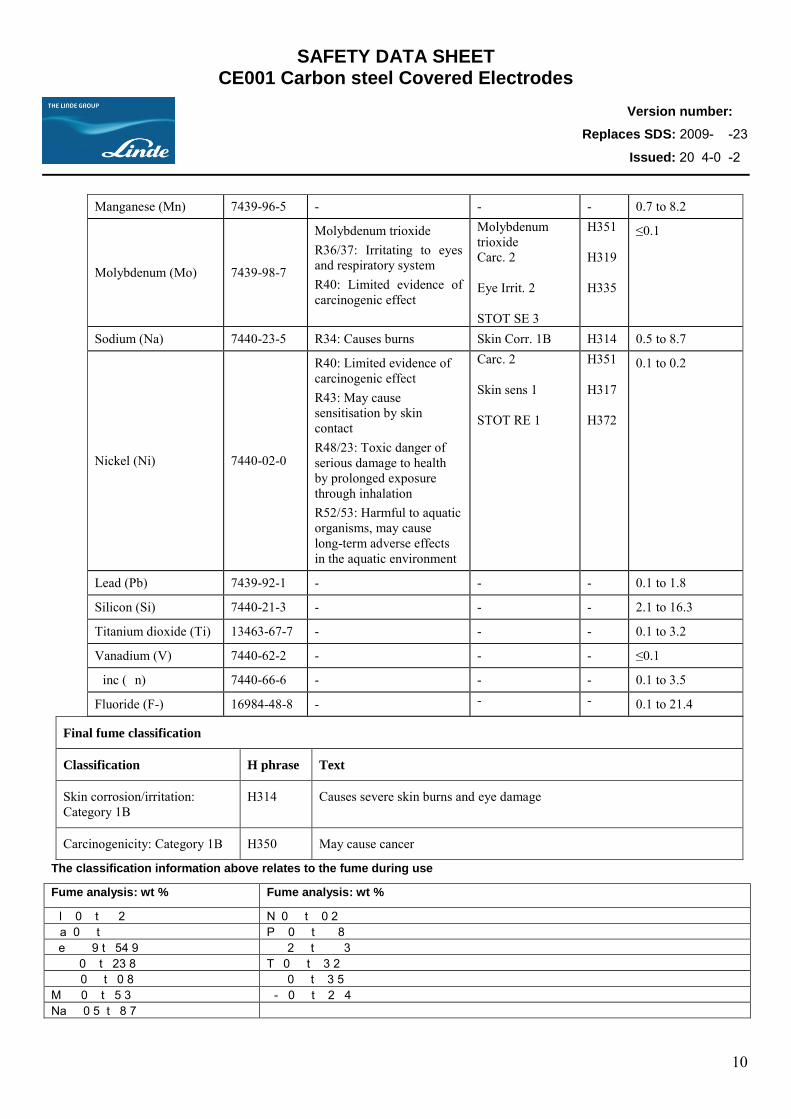
SAFETY DATA SHEET CE001 Carbon steel Covered Electrodes
Version number: 1
Replaces SDS: 2009-11-23
Issued: 2014-01-21
10
Manganese (Mn) 7439-96-5 - - - 0.7 to 8.2
Molybdenum (Mo) 7439-98-7
Molybdenum trioxide R36/37: Irritating to eyes and respiratory system R40: Limited evidence of carcinogenic effect
Molybdenum trioxide Carc. 2 Eye Irrit. 2 STOT SE 3
H351 H319 H335
≤0.1
Sodium (Na) 7440-23-5 R34: Causes burns Skin Corr. 1B H314 0.5 to 8.7
Nickel (Ni) 7440-02-0
R40: Limited evidence of carcinogenic effect R43: May cause sensitisation by skin contact R48/23: Toxic danger of serious damage to health by prolonged exposure through inhalation R52/53: Harmful to aquatic organisms, may cause long-term adverse effects in the aquatic environment
Carc. 2 Skin sens 1 STOT RE 1
H351 H317 H372
0.1 to 0.2
Lead (Pb) 7439-92-1 - - - 0.1 to 1.8
Silicon (Si) 7440-21-3 - - - 2.1 to 16.3
Titanium dioxide (Ti) 13463-67-7 - - - 0.1 to 3.2
Vanadium (V) 7440-62-2 - - - ≤0.1
Zinc (Zn) 7440-66-6 - - - 0.1 to 3.5
Fluoride (F-) 16984-48-8 - - - 0.1 to 21.4
Final fume classification
Classification H phrase Text
Skin corrosion/irritation: Category 1B
H314 Causes severe skin burns and eye damage
Carcinogenicity: Category 1B H350 May cause cancer
The classification information above relates to the fume during use
Fume analysis: wt % Fume analysis: wt %
Al 0.1 to 1.2 Ni 0.1 to 0.2 Ca 0.1 to 11.6 Pb 0.1 to 1.8 Fe 11.9 to 54.9 Si 2.1 to 16.3 K 0.6 to 23.8 Ti 0.1 to 3.2 Li 0.1 to 0.8 Zn 0.1 to 3.5 Mg 0.1 to 5.3 F- 0.1 to 21.4 Na 0.5 to 8.7
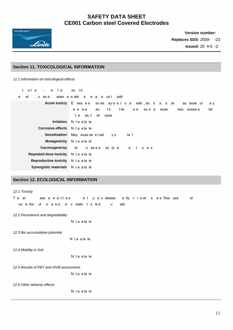
SAFETY DATA SHEET CE001 Carbon steel Covered Electrodes
Version number: 1
Replaces SDS: 2009-11-23
Issued: 2014-01-21
11
Section 11. TOXICOLOGICAL INFORMATION
11.1 Information on toxicological effects
Conditions to avoid: none in the form supplied
When welding, fumes and gases generated can be dangerous to health.
Acute toxiciy Excessive exposures may affect human health, as follows: Aspiration may cause pulmonary
oedema and pneumonitis Short-term overexposure can cause dizziness, nausea and irritation
of the nose, throat or eyes.
Irritation Not available
Corrosive effects Not available
Sensitisation May cause sensitisation by skin contact
Mutagenicity Not available
Carcinogenicity Welding fumes are possibly carcinogenic to humans
Repeated dose toxicity Not available
Reproductive toxicity Not available
Synergistic materials Not available
Section 12. ECOLOGICAL INFORMATION
12.1 Toxicity
The welding process can effect the environment if fume is released directly into the atmosphere. Residues from welding
consumables could degrade and accumulate into soils and ground water.
12.2 Persistence and degradability
Not available
12.3 Bio accumulative potential
Not available
12.4 Mobility in Soil
Not available
12.5 Results of PBT and vPvB assessment
Not available
12.6 Other adverse effects
Not available
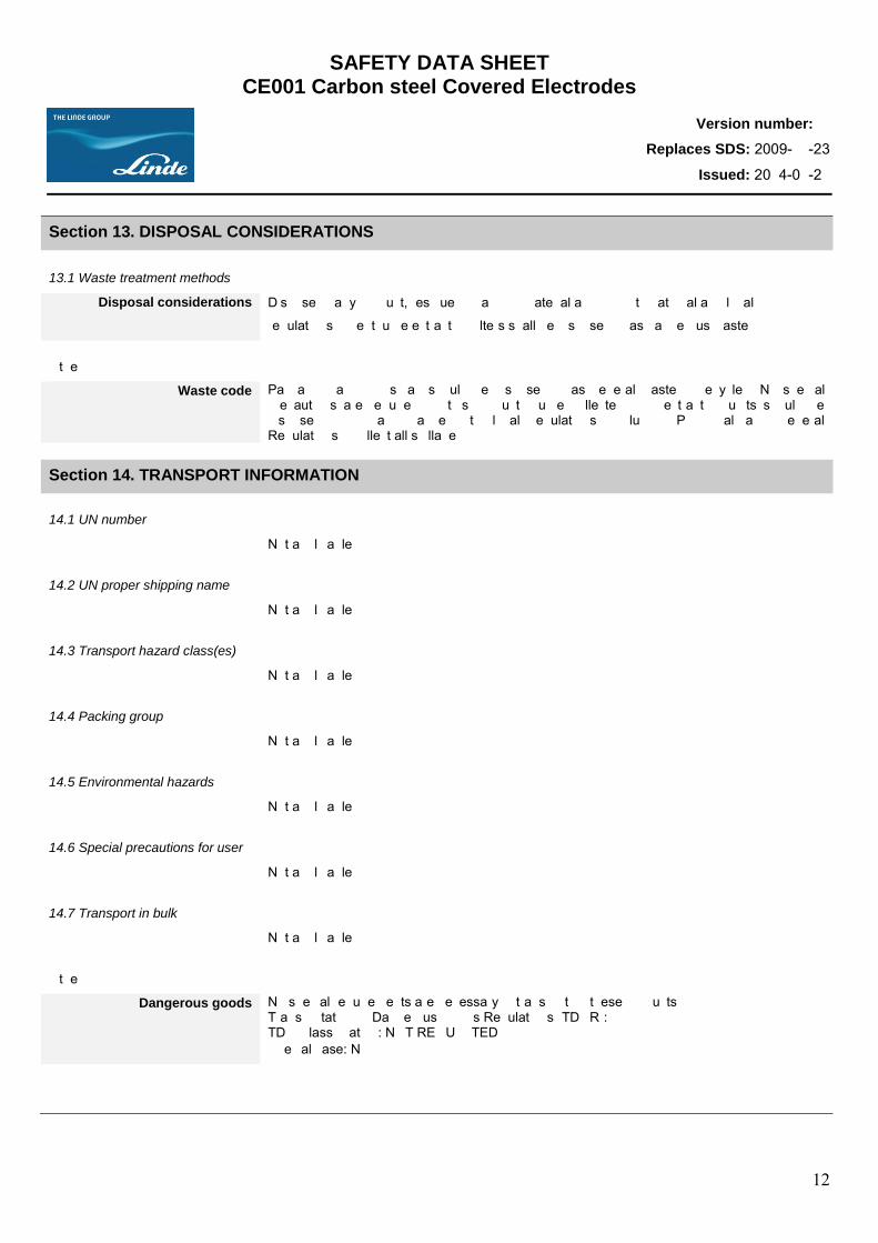
SAFETY DATA SHEET CE001 Carbon steel Covered Electrodes
Version number: 1
Replaces SDS: 2009-11-23
Issued: 2014-01-21
12
Section 13. DISPOSAL CONSIDERATIONS
13.1 Waste treatment methods
Disposal considerations Dispose of any product, residue or packing material according to national and local
regulations. Spent fume extraction filters shall be disposed of as dangerous waste.
Other
Waste code Packaging and rod scrap should be disposed of as general waste or recycled. No special precautions are required for this product. Fume collected from extraction units should be disposed of in accordance with local regulations (including Provincial and Federal Regulations). Collect all spillage.
Section 14. TRANSPORT INFORMATION
14.1 UN number
Not applicable
14.2 UN proper shipping name
Not applicable
14.3 Transport hazard class(es)
Not applicable
14.4 Packing group
Not applicable
14.5 Environmental hazards
Not applicable
14.6 Special precautions for user
Not applicable
14.7 Transport in bulk
Not applicable
Other
Dangerous goods No special requirements are necessary in transporting these products. Transportation of Dangerous Goods Regulations (TDGR): TDG Classification: NOT REGULATED Special case: N/Ap
SAFETY DATA SHEET CE001 Carbon steel Covered Electrodes
Version number: 1
Replaces SDS: 2009-11-23
Issued: 2014-01-21
13
Section 15. REGUATORY INFORMATION 15.1 Safety, health and environmental regulations / legislation specific for the substance or mixture.
EU reguations Refer to national Regulations. National regulations WHMIS Label Information: WARNING. Do not remove or cover this Warning. Protect yourself and
others. Read and understand this information. Electric shock can kill. Keep your head out of the fume. Arc rays and fume can affect others in your workplace. Comply with your employer’s safety practices and procedures: protect others. Safety data sheet available on request from www.lindecanada.com. WHMIS information: Product is regulated according to the Controlled Product Regulations (CPR) in Canada. This product has been classified in accordance with the hazard criteria of the Controlled Products Regulations (CPR) and this SDS contains all the information required by the CPR. WHMIS classification: D2A - Toxic Material with other effects.
15.2 Chemical safety assessment
Not available
Section 16. OTHER INFORMATION
References to key literature and data sources
The customer should provide this Safety Data Sheet to any person involved in the materials use or further distribution. The Linde Group requests the users (or distributors) of this product to read this Safety Data Sheet carefully before usage. Prepared by LINDE CANADA LIMITED References Safety Data Sheets from manufacturer/supplier. Canadian Centre for Occupational Health and Safety, CCInfoWeb databases, 2014.
Phrase meaning Abbreviations ACGIH American Conference of Governmental Industrial Hygienists CAS Chemical Abstract Service IARC International Agency for Research on Cancer LC Lethal concentration LD Lethal Dosage N/Ap Not applicable N/Av Not available NIOSH National Institute for Occupational Safety and Health STEL Short-term Exposure Limit TLV Threshold Limit Value TWA Time Weighted Average WHMIS Workplace Hazardous Materials Information System
Other Manufacturer’s notes The information contained in this Safety Data Sheet relates only to the specific materials
designated and may not be valid for such material used in combination with any other material or in any process. Information is given in good faith and is based on the latest information available to The Linde Group and is, to the best of The Linde Group’s knowledge and belief, accurate and reliable at the time of preparation. However, no representation, warranty or guarantee is made as to the accuracy, reliability or completeness of the information, and The Linde Group assumes no responsibility and disclaims any liability incurred in using this information. The product is supplied on the condition that the user accepts the responsibility to satisfy himself as to the suitability and completeness of such information for his own particular use. Freedom from patent rights must not be assumed. Read this Safety Data Sheet carefully and become aware of hazards implied and the safety information.
End of document
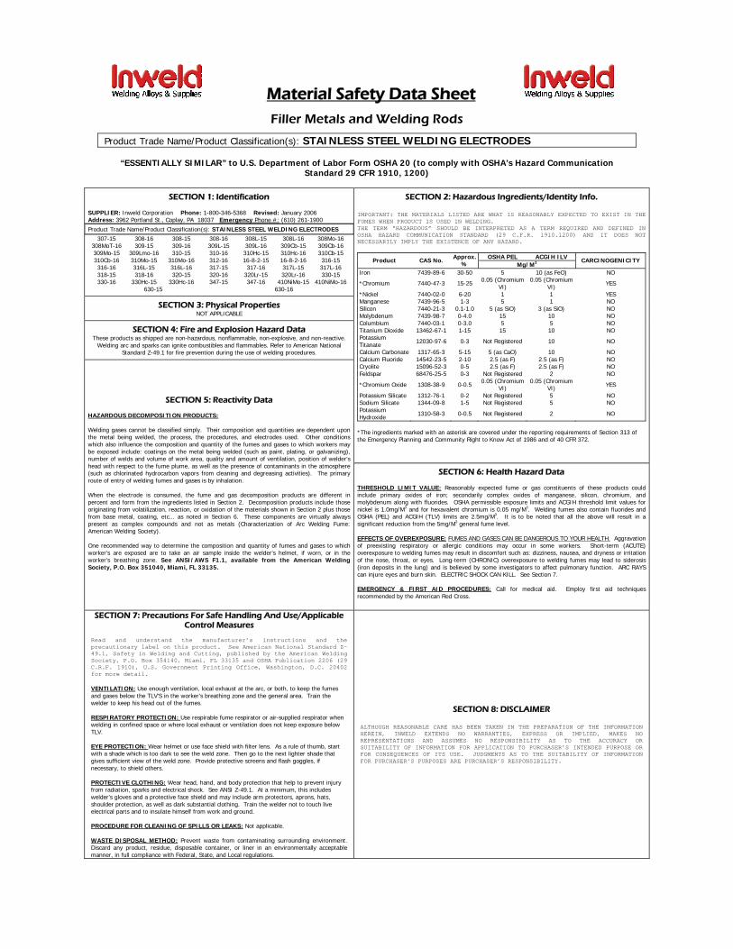
Material Safety Data Sheet
Filler Metals and Welding Rods
Product Trade Name/Product Classification(s): STAINLESS STEEL WELDING ELECTRODES
“ESSENTIALLY SIMILAR” to U.S. Department of Labor Form OSHA 20 (to comply with OSHA’s Hazard Communication
Standard 29 CFR 1910, 1200)
SECTION 1: Identification SUPPLIER: Inweld Corporation Phone: 1-800-346-5368 Revised: January 2006 Address: 3962 Portland St., Coplay, PA 18037 Emergency Phone #: (610) 261-1900
Product Trade Name/Product Classification(s): STAINLESS STEEL WELDING ELECTRODES
307-15 308-16 308-15 308-16 308L-15 308L-16 308Mo-16 308MoT-16 309-15 309-16 309L-15 309L-16 309Cb-15 309Cb-16 309Mo-15 309Lmo-16 310-15 310-16 310Hc-15 310Hc-16 310Cb-15 310Cb-16 310Mo-15 310Mo-16 312-16 16-8-2-15 16-8-2-16 316-15 316-16 316L-15 316L-16 317-15 317-16 317L-15 317L-16 318-15 318-16 320-15 320-16 320Lr-15 320Lr-16 330-15 330-16 330Hc-15 330Hc-16 347-15 347-16 410NiMo-15 410NiMo-16
630-15 630-16 SECTION 3: Physical Properties
NOT APPLICABLE
SECTION 4: Fire and Explosion Hazard Data These products as shipped are non-hazardous, nonflammable, non-explosive, and non-reactive.
Welding arc and sparks can ignite combustibles and flammables. Refer to American National Standard Z-49.1 for fire prevention during the use of welding procedures.
SECTION 2: Hazardous Ingredients/Identity Info.
IMPORTANT: THE MATERIALS LISTED ARE WHAT IS REASONABLY EXPECTED TO EXIST IN THE FUMES WHEN PRODUCT IS USED IN WELDING. THE TERM “HAZARDOUS” SHOULD BE INTERPRETED AS A TERM REQUIRED AND DEFINED IN OSHA HAZARD COMMUNICATION STANDARD (29 C.F.R. 1910.1200) AND IT DOES NOT NECESSARILY IMPLY THE EXISTENCE OF ANY HAZARD.
OSHA PEL ACGIH ILV Product CAS No. Approx. % Mg/M3
CARCINOGENICITY
Iron 7439-89-6 30-50 5 10 (as FeO) NO
*Chromium 7440-47-3 15-25 0.05 (Chromium VI)
0.05 (Chromium VI) YES
*Nickel 7440-02-0 6-20 1 1 YES Manganese 7439-96-5 1-3 5 1 NO Silicon 7440-21-3 0.1-1.0 5 (as SiO) 3 (as SiO) NO Molybdenum 7439-98-7 0-4.0 15 10 NO Columbium 7440-03-1 0-3.0 5 5 NO Titanium Dioxide 13462-67-1 1-15 15 10 NO Potassium Titanate 12030-97-6 0-3 Not Registered 10 NO
Calcium Carbonate 1317-65-3 5-15 5 (as CaO) 10 NO Calcium Fluoride 14542-23-5 2-10 2.5 (as F) 2.5 (as F) NO Cryolite 15096-52-3 0-5 2.5 (as F) 2.5 (as F) NO Feldspar 68476-25-5 0-3 Not Registered 2 NO
*Chromium Oxide 1308-38-9 0-0.5 0.05 (Chromium VI)
0.05 (Chromium VI) YES
Potassium Silicate 1312-76-1 0-2 Not Registered 5 NO Sodium Silicate 1344-09-8 1-5 Not Registered 5 NO Potassium Hydroxide 1310-58-3 0-0.5 Not Registered 2 NO
*The ingredients marked with an asterisk are covered under the reporting requirements of Section 313 of the Emergency Planning and Community Right to Know Act of 1986 and of 40 CFR 372.
SECTION 5: Reactivity Data
HAZARDOUS DECOMPOSITION PRODUCTS: Welding gases cannot be classified simply. Their composition and quantities are dependent upon the metal being welded, the process, the procedures, and electrodes used. Other conditions which also influence the composition and quantity of the fumes and gases to which workers may be exposed include: coatings on the metal being welded (such as paint, plating, or galvanizing), number of welds and volume of work area, quality and amount of ventilation, position of welder’s head with respect to the fume plume, as well as the presence of contaminants in the atmosphere (such as chlorinated hydrocarbon vapors from cleaning and degreasing activities). The primary route of entry of welding fumes and gases is by inhalation. When the electrode is consumed, the fume and gas decomposition products are different in percent and form from the ingredients listed in Section 2. Decomposition products include those originating from volatilization, reaction, or oxidation of the materials shown in Section 2 plus those from base metal, coating, etc... as noted in Section 6. These components are virtually always present as complex compounds and not as metals (Characterization of Arc Welding Fume: American Welding Society). One recommended way to determine the composition and quantity of fumes and gases to which worker’s are exposed are to take an air sample inside the welder’s helmet, if worn, or in the worker’s breathing zone. See ANSI/AWS F1.1, available from the American Welding Society, P.O. Box 351040, Miami, FL 33135.
SECTION 6: Health Hazard Data THRESHOLD LIMIT VALUE: Reasonably expected fume or gas constituents of these products could include primary oxides of iron; secondarily complex oxides of manganese, silicon, chromium, and molybdenum along with fluorides. OSHA permissible exposure limits and ACGIH threshold limit values for nickel is 1.0mg/M3 and for hexavalent chromium is 0.05 mg/M3. Welding fumes also contain fluorides and OSHA (PEL) and ACGIH (TLV) limits are 2.5mg/M3. It is to be noted that all the above will result in a significant reduction from the 5mg/M3 general fume level. EFFECTS OF OVEREXPOSURE: FUMES AND GASES CAN BE DANGEROUS TO YOUR HEALTH. Aggravation of preexisting respiratory or allergic conditions may occur in some workers. Short-term (ACUTE) overexposure to welding fumes may result in discomfort such as: dizziness, nausea, and dryness or irritation of the nose, throat, or eyes. Long-term (CHRONIC) overexposure to welding fumes may lead to siderosis (iron deposits in the lung) and is believed by some investigators to affect pulmonary function. ARC RAYS can injure eyes and burn skin. ELECTRIC SHOCK CAN KILL. See Section 7. EMERGENCY & FIRST AID PROCEDURES: Call for medical aid. Employ first aid techniques recommended by the American Red Cross.
SECTION 7: Precautions For Safe Handling And Use/Applicable Control Measures
Read and understand the manufacturer’s instructions and the precautionary label on this product. See American National Standard Z-49.1, Safety in Welding and Cutting, published by the American Welding Society, P.O. Box 354140, Miami, FL 33135 and OSHA Publication 2206 (29 C.R.F. 1910), U.S. Government Printing Office, Washington, D.C. 20402 for more detail. VENTILATION: Use enough ventilation, local exhaust at the arc, or both, to keep the fumes and gases below the TLV’S in the worker’s breathing zone and the general area. Train the welder to keep his head out of the fumes. RESPIRATORY PROTECTION: Use respirable fume respirator or air-supplied respirator when welding in confined space or where local exhaust or ventilation does not keep exposure below TLV. EYE PROTECTION: Wear helmet or use face shield with filter lens. As a rule of thumb, start with a shade which is too dark to see the weld zone. Then go to the next lighter shade that gives sufficient view of the weld zone. Provide protective screens and flash goggles, if necessary, to shield others. PROTECTIVE CLOTHING: Wear head, hand, and body protection that help to prevent injury from radiation, sparks and electrical shock. See ANSI Z-49.1. At a minimum, this includes welder’s gloves and a protective face shield and may include arm protectors, aprons, hats, shoulder protection, as well as dark substantial clothing. Train the welder not to touch live electrical parts and to insulate himself from work and ground. PROCEDURE FOR CLEANING OF SPILLS OR LEAKS: Not applicable. WASTE DISPOSAL METHOD: Prevent waste from contaminating surrounding environment. Discard any product, residue, disposable container, or liner in an environmentally acceptable manner, in full compliance with Federal, State, and Local regulations.
SECTION 8: DISCLAIMER ALTHOUGH REASONABLE CARE HAS BEEN TAKEN IN THE PREPARATION OF THE INFORMATION HEREIN, INWELD EXTENDS NO WARRANTIES, EXPRESS OR IMPLIED, MAKES NO REPRESENTATIONS AND ASSUMES NO RESPONSIBILITY AS TO THE ACCURACY OR SUITABILITY OF INFORMATION FOR APPLICATION TO PURCHASER’S INTENDED PURPOSE OR FOR CONSEQUENCES OF ITS USE. JUDGMENTS AS TO THE SUITABILITY OF INFORMATION FOR PURCHASER’S PURPOSES ARE PURCHASER’S RESPONSIBILITY.
Erik Martinez [email protected] 519.340.4567