Embed Size (px)
Citation preview
7/31/2019 EMI Sources
http://slidepdf.com/reader/full/emi-sources 1/17
INTRODUCTION
The sources of electromagnetic interference are both natural and human-made.
Natural sources include sun and stars, as well as phenomena such as
atmospherics, lightning, thunderstorms, and electrostatic discharge. On the other
hand, electromagnetic interference is also generated during the practical use of avariety of electrical, electronic, and electromechanical apparatus. This interference,
which is generated by various equipment and appliances, is human-made. We will
mention several sources of electromagnetic interference.
This report presents a description of the sources and nature of natural
electromagnetic noise. Although electromagnetic pulses (EMPs) caused by nuclear
explosions cannot be said to be a natural phenomenon, the electromagnetic
disturbances generated by an EMP are analogous to disturbances caused by
natural atmospheric phenomena in their most severe and extreme form. It is,
therefore, convenient for the purpose of analysis to treat electromagnetic pulses
along with natural phenomena like lightning and electrostatic discharge.

7/31/2019 EMI Sources
http://slidepdf.com/reader/full/emi-sources 2/17
ELECTROMAGTECIC INTERFERENCE
Electromagnetic Interference (EMI) is everywhere, inside and outside of all
electrical equipment. Man-made EMI is on the increase daily, due to the increased
use of electrical and electronic equipment. The successful detection and
elimination of EMI require a systematic search for EMI sources as well as aknowledge of interference susceptibilities of the equipment. Familiarity with the
environment in which the equipment will work as well as possible alternative
environments are fundamental to effective EMI reduction to a required minimum
level.
What is Electromagnetic Interference (EMI)?
Every electronic device is a source of radiated electromagnetic fields called
radiated emissions. These are often an accidental by-product of the design.
Electromagnetic interference (EMI) is the degradation in a device‟s performance
due to these fields which make up the “electromagnetic environment.” Every
electronic device is susceptible to EMI. Its influence can be seen all around us. The
results include: “ghosts” in TV picture reception, taxicab radio interference with a
police radio system, power line transient interference with personal computers, and
self-oscillation of a radio receiver or transmitter circuit.
Electromagnetic compatibility (EMC) is when a device functions satisfactorily
without introducing intolerable disturbances to the electromagnetic environment or
to the other devices therein. EMC is achieved when electronic devices coexist in
harmony, such that each device functions according to its intended purpose in the
presence of, and in spite of, the others.
EMI is the problem that occurs when unwanted voltages or currents are present to
influence performance. EMC is the solution. This is achieved by applying proven
design techniques, the use of which assures a system relatively free of EMI
problems.
Telecommunication is made possible through radio waves which are traveling
electromagnetic waves. Every wireless communication device including cellphones, radio, GPS tracking devices and satellite communication devices rely on
radio waves for transmission and reception of signals. What leads to
electromagnetic interference is the property of these radio waves to superimpose
on each other.

7/31/2019 EMI Sources
http://slidepdf.com/reader/full/emi-sources 3/17
As we know from radios, its receiver antenna is tuned to receiving a certain band of
radio frequencies. All signals in that range are received by the antenna,
irrespective of what source it is radiated from. Any other electric source that
transmits electromagnetic radiation in those frequency bands will cause
interference in the reception of that antenna.
Remembering some elementary physics, every changing electric field gives rise to
a magnetic field and every oscillating electric field gives rise to a magnetic field.
That is how electromagnetic waves travel through space. They need no
transmission medium. Any received electromagnetic wave generates an EMF
(electromotive force) in the antenna conductor which leads to noise in the
connected circuit.
The absence of selectivity in reception of electromagnetic waves leads to
interference. This problem plagues amplitude modulated (AM) radio broadcasts,
which possess selectivity. However, modern wireless networking technologies (like
Wi-Fi) have selectivity in receiving radio waves. A plethora of techniques like
frequency hopping, error correction and spread spectrum have been devised that
reduce noise due to electromagnetic interference to a minimum.
Sources and Types of EMI
Let‟s classify EMI in terms of its causes and sources. The cause of EMI may be
within the system, in which case it is termed an intrasystem problem or from the
outside, in which case it is called an intersystem problem . The term emitter is
commonly used to denote the source of EMI. The term susceptor is used to
designate a victim device. Both intrasystem and intersystem EMI generally can be
controlled by the system design engineer if she or he just follows some design
guidelines and techniques.
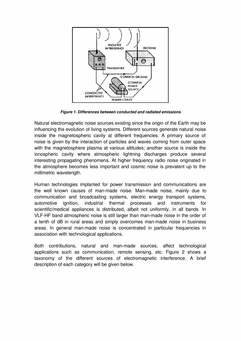
The sources of EMI can be classified as natural and artificial (man-made). The
origins of EMI are basically undesired conducted emissions (voltages and/or
currents), or radiated emissions (electric and/or magnetic fields). Conducted
emissions are those currents that are carried by metallic paths (the unit‟s power
cord) and place on the common power net. Here they may cause interference withother devices also connected to this net. Radiated emissions concern the electric
fields radiated by the device which may be received by other electronic devices
causing interference in those other devices. Figure 1 illustrates the conceptual
difference between conducted and radiated path.
7/31/2019 EMI Sources
http://slidepdf.com/reader/full/emi-sources 4/17
Figure 1. Differences between conducted and radiated emissions
Natural electromagnetic noise sources existing since the origin of the Earth may be
influencing the evolution of living systems. Different sources generate natural noise
inside the magnetospheric cavity at different frequencies. A primary source of
noise is given by the interaction of particles and waves coming from outer space
with the magnetosphere plasma at various altitudes; another source is inside the
ionospheric cavity where atmospheric lightning discharges produce several
interesting propagating phenomena. At higher frequency radio noise originated in
the atmosphere becomes less important and cosmic noise is prevalent up to the
millimetric wavelength.
Human technologies implanted for power transmission and communications are
the well known causes of man-made noise. Man-made noise, mainly due to
communication and broadcasting systems, electric energy transport systems,
automotive ignition, industrial thermal processes and instruments for
scientific/medical appliances is distributed, albeit not uniformly, in all bands. In
VLF-HF band atmospheric noise is still larger than man-made noise in the order of
a tenth of dB in rural areas and simply overcomes man-made noise in business
areas. In general man-made noise is concentrated in particular frequencies in
association with technological applications.
Both contributions, natural and man-made sources, affect technological
applications such as communication, remote sensing, etc. Figure 2 shows a
taxonomy of the different sources of electromagnetic interference. A brief
description of each category will be given below.

7/31/2019 EMI Sources
http://slidepdf.com/reader/full/emi-sources 5/17
Figure 2. Taxonomy of EMI Sources
Natural EMI sources - Sources that are associated with natural phenomena.They include atmospheric charge/discharge phenomena such as lightening
and precipitation static and extraterrestrial sources including radiation from the
sum and galactic sources such as radio stars, galaxies, and other cosmic
sources. As shown in the above diagram, all natural sources are classified as
broadband, incoherent, radiated, and unintentional.
Man-made EMI sources - Sources associated with man-made devices such
as power lines, auto ignition, fluorescent lights, etc.
Broadband EMI - Electromagnetic conducted and radiated signals whose
amplitude variation as a function of frequency extends over a frequency range
greater than the bandwidth of the receptor.
Narrowband EMI - Electromagnetic conducted and radiated signals whose
amplitude variation as a function of frequency extends over a frequency range
narrower than the bandwidth of the receptor.
Coherent broadband signals - Neighboring components of the signal (in the
frequency domain) has a well-defined amplitude, frequency, and phase
relationship.
Natural Broadband Incoherent Radiated Unintentional
Man-made
Broadband
Coherent
Conducted
Radiated
Incoherent
Conducted
Radiated
Narrowband Coherent
Conducted
Intentional
Unintentional
Radiated
Intentional
Unintentional
Restricted
7/31/2019 EMI Sources
http://slidepdf.com/reader/full/emi-sources 6/17
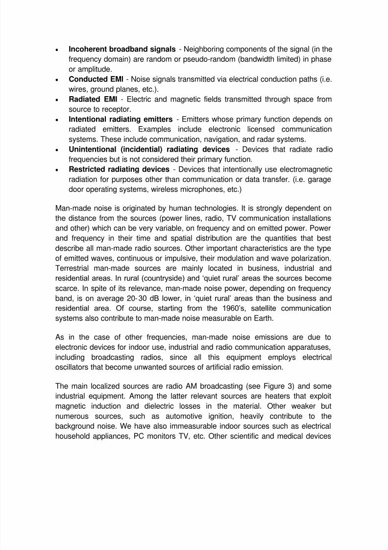
Incoherent broadband signals - Neighboring components of the signal (in the
frequency domain) are random or pseudo-random (bandwidth limited) in phase
or amplitude.
Conducted EMI - Noise signals transmitted via electrical conduction paths (i.e.
wires, ground planes, etc.).
Radiated EMI - Electric and magnetic fields transmitted through space from
source to receptor.
Intentional radiating emitters - Emitters whose primary function depends on
radiated emitters. Examples include electronic licensed communication
systems. These include communication, navigation, and radar systems.
Unintentional (incidential) radiating devices - Devices that radiate radio
frequencies but is not considered their primary function.
Restricted radiating devices - Devices that intentionally use electromagnetic
radiation for purposes other than communication or data transfer. (i.e. garage
door operating systems, wireless microphones, etc.)
Man-made noise is originated by human technologies. It is strongly dependent on
the distance from the sources (power lines, radio, TV communication installations
and other) which can be very variable, on frequency and on emitted power. Power
and frequency in their time and spatial distribution are the quantities that best
describe all man-made radio sources. Other important characteristics are the type
of emitted waves, continuous or impulsive, their modulation and wave polarization.
Terrestrial man-made sources are mainly located in business, industrial and
residential areas. In rural (countryside) and „quiet rural‟ areas the sources become
scarce. In spite of its relevance, man-made noise power, depending on frequencyband, is on average 20-30 dB lower, in „quiet rural‟ areas than the business and
residential area. Of course, starting from the 1960‟s, satellite communication
systems also contribute to man-made noise measurable on Earth.
As in the case of other frequencies, man-made noise emissions are due to
electronic devices for indoor use, industrial and radio communication apparatuses,
including broadcasting radios, since all this equipment employs electrical
oscillators that become unwanted sources of artificial radio emission.
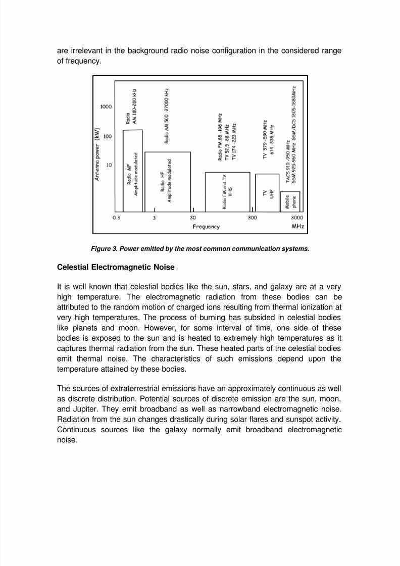
The main localized sources are radio AM broadcasting (see Figure 3) and someindustrial equipment. Among the latter relevant sources are heaters that exploit
magnetic induction and dielectric losses in the material. Other weaker but
numerous sources, such as automotive ignition, heavily contribute to the
background noise. We have also immeasurable indoor sources such as electrical
household appliances, PC monitors TV, etc. Other scientific and medical devices
7/31/2019 EMI Sources
http://slidepdf.com/reader/full/emi-sources 7/17
are irrelevant in the background radio noise configuration in the considered range
of frequency.
Figure 3. Power emitted by the most common communication systems.
Celestial Electromagnetic Noise
It is well known that celestial bodies like the sun, stars, and galaxy are at a very
high temperature. The electromagnetic radiation from these bodies can beattributed to the random motion of charged ions resulting from thermal ionization at
very high temperatures. The process of burning has subsided in celestial bodies
like planets and moon. However, for some interval of time, one side of these
bodies is exposed to the sun and is heated to extremely high temperatures as it
captures thermal radiation from the sun. These heated parts of the celestial bodies
emit thermal noise. The characteristics of such emissions depend upon the
temperature attained by these bodies.
The sources of extraterrestrial emissions have an approximately continuous as well
as discrete distribution. Potential sources of discrete emission are the sun, moon,and Jupiter. They emit broadband as well as narrowband electromagnetic noise.
Radiation from the sun changes drastically during solar flares and sunspot activity.
Continuous sources like the galaxy normally emit broadband electromagnetic
noise.

7/31/2019 EMI Sources
http://slidepdf.com/reader/full/emi-sources 8/17
The level of electromagnetic noise emitted by a cosmic source does not vary
appreciably with time, unless the source itself undergoes a change which results in
a corresponding variation in the emitted electromagnetic noise. However, the
cosmic noise received at a given point on earth varies with the time of the day
because earth rotates around the sun and also revolves around its own axis.
The broad spectrum noise extending from meter wavelengths to centimeter and
lower wavelengths was originally linked with our own galaxy. It was subsequently
discovered to emanate from all directions in the cosmos. Hence, what was
originally described as galactic noise was later given the more general name of
cosmic noise.
EFFECTS OF EMI
There are numerous factors that affect radio wave propagation, which include
transmission power, antenna gain, attenuation factors, and noise. In addition, there
are ionospheric and tropospheric conditions that also have a dramatic effect on the
propagation of radio transmission through free-space. The Basic Effects are:
Atmospheric Effects
The transmission of High Frequency HF signals (3 MHz - 30 MHz) for distances
greater than approximately 100 miles depends on sky wave propagation, due to
the ionization levels that exist in the ionosphere. The effects of the ionosphere
on signals in the medium and high frequency regions are more pronounced than
at VHF/UHF ranges (30 MHz –300 MHz/300 MHz –3 GHz) .The transmission of
VHF/UHF signals depend on ground wave propagation and almost always follow
line-of-sight paths, which requires no obstructions between the transmitting and
receiving stations.
In effective satellite communication the calculation of free-space transmission
loss is the primary consideration effect. In addition, noise levels from terrestrial,
man-made, and cosmic sources can also interfere and negatively affect signal
propagation.
Transients due to EMI
Electrical disturbances pose a great threat to electrical equipment and data.
Electrical disturbances go by various names such as spikes, surges, and
transient surge voltages. Regardless of the name, the effects of these
disturbances remain the same: disruption, degradation and damage. With the
increasing popularity of computer networking, the effect of transient surges on

7/31/2019 EMI Sources
http://slidepdf.com/reader/full/emi-sources 9/17
communication lines is also of great importance. Transient surges may cause
serious damage to communication interfaces inside a building. There are
different ways a transient surge may be created, a single surge suppression
layer applied to incoming lines may not be appropriate to completely shield the
internal lines and equipment from transient voltages. Transients can be present
on any conductor such as utility power lines, telephone, data, and signal lines.
Spikes, a type of transient surge, are short-term over-voltages, which are usually
measured in milliseconds. This unwanted excess of electrical energy could be
created easily on any conductive line. The energy content of transients can be
enormous and can damage equipment, or cause it to malfunction by giving
faulty signals due to inaccurate voltage levels. Equipment driven by
microprocessors and other integrated circuits (IC) are especially vulnerable to
transient voltage surges. Inductive coupling, created from various sources, is
usually the cause for transients specific to data lines.
A transformer produces a magnetic field extending from a coiled wire in the
primary, which induces a voltage in the coiled wire of the secondary. Under the
same principles, wires that run adjacent to one another within a building can
magnetically couple transients, as shown in Figure 4. This coupling can be
caused by a power line, which induces a voltage in an adjacent data line, or
from one data line to another (which is usually referred to as crosstalk).
Figure 4. Inductive coupling.
Lightning can cause a much more powerful kind of magnetic coupling, which can
cause sudden damages to multiple items in a single strike. Figure 5 shows a
lightning bolt striking the ground. This lightning bolt is surrounded by a very
powerful magnetic field. In much the same way a magnetic field from one
conductor can induce transients on an adjacent conductor, the magnetic field of

7/31/2019 EMI Sources
http://slidepdf.com/reader/full/emi-sources 10/17
a lightning strike can induce power in an external power line without actually
striking the line directly.
Figure 5. Magnetic field created from a lightning strike
There are other major sources of coupling that can be detrimental to data
infrastructure. When planning or inspecting the layout of data lines, the following
sources of inductive coupling should be addressed:
Data lines that are draped over power conduits.
Running data cables near lightning down conductor (down conductors are lines
or structures in a building designed to convey lighting discharge current in a
building to ground).
Running data cables near building steel (especially in the vicinity of lightningdown conductors).
Running data lines too close to fluorescent lighting (which emit EMI).
Much of the electrical equipment seen today is built on integrated circuit and
microprocessor technology. Because of certain characteristics common to
integrated circuits and microprocessors, this equipment is especially sensitive to
transient voltage surges. Microprocessor based and controlled devices can be
found in almost every setting. Some of this electronic equipment includes
computers and their peripherals, computer and data networks (such as LANs),
telecommunication equipments, medical diagnostic equipments, CNC productionmachinery, radio equipment, televisions, satellite television equipment, electronic
cash registers, copy machines, fax machines, etc. These equipments are
commonly found connected to some form of data line for communication purposes.

7/31/2019 EMI Sources
http://slidepdf.com/reader/full/emi-sources 11/17
Common failures produced by transients
The most common failures produced by transients within electronic devices are
disruptive, dissipative, and destructive.
Disruptive effects: are usually encountered when a transient enters theequipment by inductive coupling (either over data or power lines). The
electronic components then try to process the transient as a valid logic
command. The result is system lock-up, malfunctions, erroneous output, lost or
corrupted files, and a variety of other undesirable effects.
Dissipative effects: are associated with repeated stresses to IC components.
The materials used to fabricate ICs can withstand a certain number of repeated
energy level surges, but not for an extended period. Long-term degradation will
eventually cause the components to be rendered inoperable.
Destructive effects: include all conditions where transients with high levels of
energy cause equipment to fail immediately. Often, there is physical damage
apparent, like burnt and/or cracked PC boards and components, melting of
electronic components, or other obvious indications.
Receptors of EMI
Any EMI situation requires not only an emission source but also a receptor. A
receptor is also called a "victim" source because it consists of any device, when
exposed to conducted or radiated electromagnetic energy from emitting sources,will degrade or malfunction in performance. Many devices can be emission sources
and receptors simultaneously. For example, most communication electronic
systems can be emission and receptor sources because they contain transmitters
and receivers. Figure 6 shows taxonomy of different receptors that are susceptible
to EMI. Similar to the emission source taxonomy, receptors can be divided into
natural and man-made receptors. A brief description of each category will be given
below.

7/31/2019 EMI Sources
http://slidepdf.com/reader/full/emi-sources 12/17
Figure 6. Taxonomy of EMI receptors
Natural receptors: Natural receptors include humans, animals, and plants.
Man-made EMI receptors: Man-made receptors can be categorized into 4
categories: communication electronic receivers, amplifiers, industrial andcomsumer devices, and RADHAZ.
Communication electronic receivers: These receivers include broadcast
receivers, communication receivers, relay communication receivers, and
radar receivers.
Amplifiers: Amplifiers include IF, video, and audio amplifiers.
Industrial and consumer receptors: Industrial receptors include digital
computers, industrial process controls, electronic test equipments,
biomedical instruments, and public address systems and intercoms.
Consumer receptors include radio and TV receivers, hi-fi stereoequipment, electronic musical instruments, and climate control systems.
RADHAZ: This category includes radiation hazards to electro-explosive
devices and fuels. RADHAZ is an acronym for RADiation HAZards, the
name given by the U. S. Department of Defense to the program that is
determining the extent of radiation hazards and methods for controlling
them.
Setting the ground rules.
No single operating agency has jurisdiction over all systems to dictate the action
needed to achieve EMC. Thus, EMC is usually achieved by industrial association,
voluntary regulation, government-enforced regulation and negotiated agreements
among the affected parties. Frequency plays a significant role in EMC. For
frequency allocation purposes, the world is divided into three regions:

7/31/2019 EMI Sources
http://slidepdf.com/reader/full/emi-sources 13/17
Region 1 - Europe, Africa, the formerly USSR portion of Asia, Asia-Minor, and the
Arabian Peninsula.
Region 2 - North and South Americas.
Region 3 - Australia and the rest of Asia including Hawaii.
Frequency allocations and assignments are made according to the constraints
established by the international treaties. The Radio Regulations resulting from such
international treaties are published by the International Telecommunication Union
(ITU). The Federal Communications Commission (FCC) has the authority over
radio and wire communications in the United States.
The FCC has set limits on the radiated and conducted emissions of electronic
devices including electronic typewriters, calculators, televisions, printers, modems,
and personal computers. It is illegal to market an electronic device in the UnitedStates unless its radiated and conducted emissions have been measured and do
not exceed the limits of FCC regulations. Therefore, any electronic device
designed today that is designed without incorporating EMC design principles will
probably fail to comply with the FCC limits.
EMI control techniques.
Traditional design practices typically address EMC when an incompatibility is
discovered in a production prototype. Solutions to problems at this stage are often
superficial. Quick fixes late in the design cycle become more costly and difficult as
the complexity of the electronic system increases.
Experience has shown that efficient design occurs when EMC considerations begin
early in the design phase and continue through every stage. This includes
component selection, the design of printed circuit boards and interconnections, and
the physical packaging and location of the systems. This approach results in EMC
being designed into the system, not added on at a later time.
To control or suppress EMI, the three common means employed are grounding,
shielding, and filtering. Although each technique has a distinct role in system
design, proper grounding may sometimes minimize the need for shielding and
filtering. Also, proper shielding may minimize the need for filtering.
7/31/2019 EMI Sources
http://slidepdf.com/reader/full/emi-sources 14/17
Grounding
Grounding establishes an electrically conductive path between two points. This
is one to connect electrical and electronic elements of a system to one another
or to some reference point, which may be designated the ground. An ideal
ground plane is a zero-potential, zero-impedance body. It can be used as areference for all signals in associated circuitry, and be the point to which any
undesired current can be transferred.
Bonding is the establishment of a low impedance path between two metal
surfaces. Grounding is a circuit concept, while bonding denotes the physical
implementation of that concept. The purpose of a bond is to make a structure
homogeneous with respect to the flow of electrical currents, thus avoiding the
development of potentials between the metallic parts; such potentials may
result in EMI. Bonds provide protection from electrical shock, power circuit
current return paths, and antenna ground plane connections. They also
minimize the potential difference between the devices. Bonds have the ability
to carry large fault current.
There are two types of bonding - direct and indirect. The direct bond is a metal-
to-metal contact between the connecting elements, while an indirect bond is a
contact via conductive jumpers.
The following guidelines are recommended for effective grounding:
1) All grounding must be done via excellent electrical connection between the
ground reference and the item to be grounded. Grounding joints of
dissimilar materials must be avoided.
2) In multiconductor cables, ground all unused lines at one end.
3) Ground the shell of all connectors in high EM1 areas.
4) If ground potentials exist between distant areas to be interconnected and
cannot be removed by use of grounding techniques, consider using a
transformer for isolation.
5) Running ground wires in the most direct route with as few bends and loops
as possible will minimize self-inductance and improve the ground.
Shielding
The purpose of shielding is to confine radiated energy to a specific region or to
prevent radiated energy from entering a specific region. Shields may be in the

7/31/2019 EMI Sources
http://slidepdf.com/reader/full/emi-sources 15/17
form of partitions and boxes as well as in the form of cable and connector
shields.
Shield types include solid, nonsolid (e.g. screen), and braid, as is used on
cables. In all cases, a shield can be characterized by its shielding
effectiveness.
The following guidelines are recommended for effective cable shielding:
1) When terminating shield cable, always keep the unshielded portion as
short as possible (normally less than 25 mm).
2) Never terminate the shield of a balanced line at both ends. Connect the
shield at the load (input) end of the line.
3) Always terminate the insulating (floating) end of a shielded cable with an
insulating sleeve that ensures that it cannot become inadvertently
grounded.
4) The shield must be completely insulated and not become grounded or
short-circuited to another cable shield as ground loops will be created.
5) Avoid or minimize the breaks in shields, such as at junction boxes, and
always maintain shield continuity and isolation from ground, through all
boxes or multipin connectors.
6) Multiconductor shield twisted pair cable should have individual insulated
shield and drain wires for each shield.
Filtering
An electrical filter is a network of lumped or distributed constant resistors,
inductors, and capacitors that offers comparatively little opposition to certain
frequencies or dc, while blocking the passage of other frequencies. A filter
provides the means whereby levels of conducted interference are substantially
reduced.
The most significant characteristic of a filter is the insertion loss (IL) which is
defined as
where V1 is the output voltage of a signal source with the filter in the circuit,
and V 2 , is the output voltage of the signal source without the use of the filter.
Lowpass filters are commonly used in EMC work. The insertion loss for the
Lowpass filters is given by

7/31/2019 EMI Sources
http://slidepdf.com/reader/full/emi-sources 16/17
Where
{
and f is the frequency.
7/31/2019 EMI Sources
http://slidepdf.com/reader/full/emi-sources 17/17
CONCLUSIONS
EMI is a major problem in the development of embedded systems. Since
embedded systems often exist in very noisy environments, even more attention
must be paid to EMC.
EMC must be taken into consideration during the design stage. Designing forEMC is a long process that starts early in the life cycle and proceeds through the
testing stage and even in the post-production stage. Therefore, EMC is a
concern for engineers at all phases of the development of an embedded system.
Electromagnetic compatibility is achieved when a device functions satisfactorily
in its electromagnetic environment without introducing intolerable disturbances.
Achieving EMC in electronic devices requires deliberate consideration at the
earlier stages of the design cycle. Such an approach and control plan permits all
avenues to EMC to be evaluated so that effective and economical solutions can
be applied.
Environmental reliability testing is used to eliminate potential problems that the
system can experience when it is operating in its natural environment.
There are many EMC standards used in the regulation of products that may
cause EMI.
EMC is a growing field because of the ever increasing density of electronic
circuits in modern systems for computation, communication, control and so forth.
Basic knowledge of EMC is particularly useful to students interested in
microwaves, electronics, or computer engineering.
EMC is a very important issue that embedded systems designers have to deal
with. Even though it is a very difficult topic, there are many practical designtechniques that can be used to design for EMC. This will greatly assist designers
who are unfamiliar with EM theory to be confident in their design for EMC.