Embed Size (px)
Citation preview

E.M.I. & A.C.
1.Two concentric circular coils, one of small radius r1 and the other of large radius
r2, such that r1 << r2, are placed co-axially with Centres coinciding. Obtain the
mutual inductance of the arrangement. ( R=r2 ,r=r1 )
1. (a) Obtain the expression for the magnetic energy stored in a solenoid in
terms of magnetic field B, area A and length l of the solenoid. (b) How does

this magnetic energy compare with the electrostatic energy stored in a
capacitor?
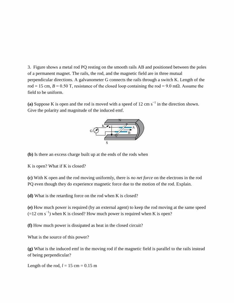
3. Figure shows a metal rod PQ resting on the smooth rails AB and positioned between the poles
of a permanent magnet. The rails, the rod, and the magnetic field are in three mutual
perpendicular directions. A galvanometer G connects the rails through a switch K. Length of the
rod = 15 cm, B = 0.50 T, resistance of the closed loop containing the rod = 9.0 mΩ. Assume the
field to be uniform.
(a) Suppose K is open and the rod is moved with a speed of 12 cm s−1
in the direction shown.
Give the polarity and magnitude of the induced emf.
(b) Is there an excess charge built up at the ends of the rods when
K is open? What if K is closed?
(c) With K open and the rod moving uniformly, there is no net force on the electrons in the rod
PQ even though they do experience magnetic force due to the motion of the rod. Explain.
(d) What is the retarding force on the rod when K is closed?
(e) How much power is required (by an external agent) to keep the rod moving at the same speed
(=12 cm s−1
) when K is closed? How much power is required when K is open?
(f) How much power is dissipated as heat in the closed circuit?
What is the source of this power?
(g) What is the induced emf in the moving rod if the magnetic field is parallel to the rails instead
of being perpendicular?
Length of the rod, l = 15 cm = 0.15 m

Magnetic field strength, B = 0.50 T
Resistance of the closed loop, R = 9 mΩ = 9 × 10⁻³
Ω
(a) Induced emf = 9 mV; polarity of the induced emf is such that end P shows positive while end
Q shows negative ends.
Speed of the rod, v = 12 cm/s = 0.12 m/s
Induced emf is given as:
e = Bvl
= 0.5 × 0.12 × 0.15
= 9 × 10⁻³
v
= 9 mV
The polarity of the induced emf is such that end P shows positive while end Q shows negative
ends.
(b) Yes; when key K is closed, excess charge is maintained by the continuous flow of current.
When key K is open, there is excess charge built up at both ends of the rods.
When key K is closed, excess charge is maintained by the continuous flow of current.
(c) Magnetic force is cancelled by the electric force set-up due to the excess charge of opposite
nature at both ends of the rod.
There is no net force on the electrons in rod PQ when key K is open and the rod is moving
uniformly. This is because magnetic force is cancelled by the electric force set-up due to the
excess charge of opposite nature at both ends of the rods.
(d) Retarding force exerted on the rod, F = IBl
Where,
I = Current flowing through the rod

(e) 9 mW; no power is expended when key K is open.
Speed of the rod, v = 12 cm/s = 0.12 m/s
Hence, power is given as:
When key K is open, no power is expended.
(f) 9 mW; power is provided by an external agent.
Power dissipated as heat = I2 R
= (1)2 × 9 × 10
−3
= 9 mW
The source of this power is an external agent.
(g) Zero
In this case, no emf is induced in the coil because the motion of the rod does not cut across the
field lines.
4.An air-cored solenoid with length 30 cm, area of cross-section 25 cm2 and number of turns
500, carries a current of 2.5 A. The current is suddenly switched off in a brief time of 10−3
s.
How much is the average back emf induced across the ends of the open switch in the circuit?
Ignore the variation in magnetic field near the ends of the solenoid.
Length of the solenoid, l = 30 cm = 0.3 m
Area of cross-section, A = 25 cm2 = 25 × 10
−4 m
2

Number of turns on the solenoid, N = 500
Current in the solenoid, I = 2.5 A
Current flows for time, t = 10−3
s
Average back emf,
Where,
= Change in flux
= NAB … (2)
Where,
B = Magnetic field strength
Where,
= Permeability of free space = 4π × 10−7
T m A−1
Using equations (2) and (3) in equation (1), we get
Hence, the average back emf induced in the solenoid is 6.5 V.
5. (a) Obtain an expression for the mutual inductance between a long straight wire and a square
loop of side a as shown in Fig. 6.21.
(b) Now assume that the straight wire carries a current of 50 A and the loop is moved to the right
with a constant velocity, v = 10 m/s.

Calculate the induced emf in the loop at the instant when x = 0.2 m.
Take a = 0.1 m and assume that the loop has a large resistance.
(a) Take a small element dy in the loop at a distance y from the long straight wire (as shown in
the given figure).
Magnetic flux associated with element
Where,
dA = Area of element dy = a dy
B = Magnetic field at distance y
I = Current in the wire
= Permeability of free space = 4π × 10−7
T m A−1
y tends from x to .

(b) Emf induced in the loop, e = B’av
Given,
I = 50 A
x = 0.2 m
a = 0.1 m
v = 10 m/s
A line charge λ per unit length is lodged uniformly onto the rim of a wheel of mass M and radius
R. The wheel has light non-conducting spokes and is free to rotate without friction about its axis
(Fig. 6.22). A uniform magnetic field extends over a circular region within the rim. It is given by,
B = − B0 k (r ≤ a; a < R)

= 0 (otherwise)
6. What is the angular velocity of the wheel after the field is suddenly switched off?
Line charge per unit length
Where,
r = Distance of the point within the wheel
Mass of the wheel = M
Radius of the wheel = R
Magnetic field,
At distance r,themagnetic force is balanced by the centripetal force i.e.,
7. An LC circuit contains a 20 mH inductor and a 50 μF capacitor with an initial charge of 10
mC. The resistance of the circuit is negligible. Let the instant the circuit is closed be t = 0.
(a) What is the total energy stored initially? Is it conserved during LC oscillations?
(b) What is the natural frequency of the circuit?
(c) At what time is the energy stored
(i) Completely electrical (i.e., stored in the capacitor)? (ii) completely magnetic (i.e., stored in
the inductor)?

(d) At what times is the total energy shared equally between the inductor and the capacitor?
(e) If a resistor is inserted in the circuit, how much energy is eventually dissipated as heat?
Inductance of the inductor, L = 20 mH = 20 × 10−3
H
Capacitance of the capacitor, C = 50 μF = 50 × 10−6
F
Initial charge on the capacitor, Q = 10 mC = 10 × 10−3
C
(a) Total energy stored initially in the circuit is given as:
Hence, the total energy stored in the LC circuit will be conserved because there is no resistor
connected in the circuit.
(b)Natural frequency of the circuit is given by the relation,
Natural angular frequency,
Hence, the natural frequency of the circuit is 103 rad/s.

(c) (i) For time period (T ), total charge on the capacitor at time t,
For energy stored is electrical, we can write Q’ = Q.
Hence, it can be inferred that the energy stored in the capacitor is completely electrical at time, t
=
(ii) Magnetic energy is the maximum when electrical energy, Q′ is equal to 0.
Hence, it can be inferred that the energy stored in the capacitor is completely magnetic at time,
(d) Q1 = Charge on the capacitor when total energy is equally shared between the capacitor and
the inductor at time t.
When total energy is equally shared between the inductor and capacitor, the energy stored in the
capacitor = (maximum energy).

Hence, total energy is equally shared between the inductor and the capacity at time,
(e) If a resistor is inserted in the circuit, then total initial energy is dissipated as heat energy in the
circuit. The resistance damps out the LC oscillation.
Angular velocity,
8. Answer the following questions:
(a) In any ac circuit, is the applied instantaneous voltage equal to the algebraic sum of the
instantaneous voltages across the series elements of the circuit? Is the same true for rms voltage?
(b) A capacitor is used in the primary circuit of an induction coil.
(c) An applied voltage signal consists of a superposition of a dc voltage and an ac voltage of high
frequency. The circuit consists of an inductor and a capacitor in series. Show that the dc signal
will appear across C and the ac signal across L.
(d) A choke coil in series with a lamp is connected to a dc line. The lamp is seen to shine
brightly. Insertion of an iron core in the choke causes no change in the lamp’s brightness. Predict
the corresponding observations if the connection is to an ac line.
(e) Why is choke coil needed in the use of fluorescent tubes with ac mains? Why can we not use
an ordinary resistor instead of the choke coil?
(a) Yes; the statement is not true for rms voltage
It is true that in any ac circuit, the applied voltage is equal to the average sum of the
instantaneous voltages across the series elements of the circuit. However, this is not true for rms
voltage because voltages across different elements may not be in phase.
(b) High induced voltage is used to charge the capacitor.
A capacitor is used in the primary circuit of an induction coil. This is because when the circuit is
broken, a high induced voltage is used to charge the capacitor to avoid sparks.
(c) The dc signal will appear across capacitor C because for dc signals, the impedance of an
inductor (L) is negligible while the impedance of a capacitor (C) is very high (almost infinite).
Hence, a dc signal appears across C. For an ac signal of high frequency, the impedance of L is
high and that of C is very low. Hence, an ac signal of high frequency appears across L.
(d) If an iron core is inserted in the choke coil (which is in series with a lamp connected to the ac
line), then the lamp will glow dimly. This is because the choke coil and the iron core increase the
impedance of the circuit.
(e) A choke coil is needed in the use of fluorescent tubes with ac mains because it reduces the
voltage across the tube without wasting much power. An ordinary resistor cannot be used instead
of a choke coil for this purpose because it wastes power in the form of heat.
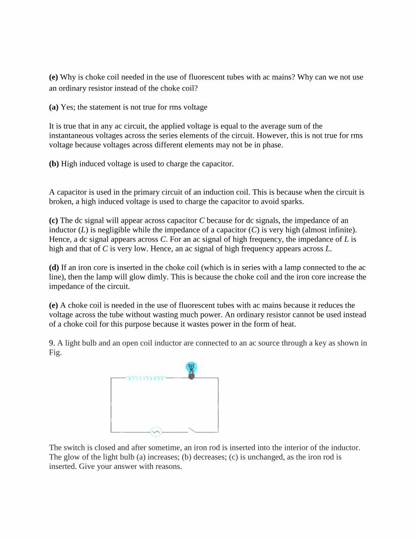
9. A light bulb and an open coil inductor are connected to an ac source through a key as shown in
Fig.
The switch is closed and after sometime, an iron rod is inserted into the interior of the inductor.
The glow of the light bulb (a) increases; (b) decreases; (c) is unchanged, as the iron rod is
inserted. Give your answer with reasons.

Solution:- As the iron rod is inserted, the magnetic field inside the coil magnetizes the iron
increasing the magnetic field inside it. Hence, the inductance of the coil increases. Consequently,
the inductive reactance of the coil increases. As a result, a larger fraction of the applied ac
voltage appears across the inductor, leaving less voltage across the bulb. Therefore, the glow of
the light bulb decreases.
10. A small town with a demand of 800 kW of electric power at 220 V is situated 15 km away
from an electric plant generating power at 440 V. The resistance of the two wire line carrying
power is 0.5 Ω per km. The town gets power from the line through a 4000-220 V step-down
transformer at a sub-station in the town.
(a) Estimate the line power loss in the form of heat.
(b) How much power must the plant supply, assuming there is negligible power loss due to
leakage?
(c) Characterise the step up transformer at the plant.
Total electric power required, P = 800 kW = 800 × 103 W
Supply voltage, V = 220 V
Voltage at which electric plant is generating power, V' = 440 V
Distance between the town and power generating station, d = 15 km
Resistance of the two wire lines carrying power = 0.5 Ω/km
Total resistance of the wires, R = (15 + 15)0.5 = 15 Ω
A step-down transformer of rating 4000 − 220 V is used in the sub-station.
Input voltage, V1 = 4000 V
Output voltage, V2 = 220 V
Rms current in the wire lines is given as:

(a) Line power loss = I2R
= (200)2 × 15
= 600 × 103 W
= 600 kW
(b) Assuming that the power loss is negligible due to the leakage of the current:
Total power supplied by the plant = 800 kW + 600 kW
= 1400 kW
(c) Voltage drop in the power line = IR = 200 × 15 = 3000 V
Hence, total voltage transmitted from the plant = 3000 + 4000
= 7000 V
Also, the power generated is 440 V.
Hence, the rating of the step-up transformer situated at the power plant is 440 V − 7000 V.

QUESTION FOR PRACTICE
1. A metallic rod of 1 m length is rotated with a frequency of 50 rev/s, with one end hinged at the
Centre and the other end at the circumference of a circular metallic ring of radius 1 m, about an
axis passing through the Centre and perpendicular to the plane of the ring (Fig.). A constant and
uniform magnetic field of 1 T parallel to the axis is present everywhere. What is the emf between
the centre and the metallic ring?
2. Answer the following questions:
(a) In any ac circuit, is the applied instantaneous voltage equal to the algebraic sum of the
instantaneous voltages across the series elements of the circuit? Is the same true for rms voltage?
(b) A capacitor is used in the primary circuit of an induction coil.
(c) An applied voltage signal consists of a superposition of a dc voltage and an ac voltage of high
frequency. The circuit consists of an inductor and a capacitor in series. Show that the dc signal
will appear across C and the ac signal across L.
(d) A choke coil in series with a lamp is connected to a dc line. The lamp is seen to shine
brightly. Insertion of an iron core in the choke causes no change in the lamp’s brightness. Predict
the corresponding observations if the connection is to an ac line.
(e) Why is choke coil needed in the use of fluorescent tubes with ac mains? Why can we not use
an ordinary resistor instead of the choke coil?
3. An inductor L of reactance XL is connected in series with a bulb B to an A.C. source as shown in the
figure. Briefly explain how does the brightness of the bulb change when (a) Number of turns of the inductor
is reduced and (b) A capacitor of reactance XC =XL is included in series in the same circuit.

4. Figure shows an inductor L and a resistance R connected in parallel to a battery through a switch. The resistance R is same as that of the coil that makes L. Two identical bulbs are put in each arm of the circuit. Which of the bulbs lights up earlier, when K is closed? Will the bulbs be equally bright after same time?
5. Figure (a), (b) and (c) Show three alternating circuits with equal currents. If frequency of
alternating emf be increased, what will be the effect on currents In the three cases. Explain.
6. A square loop of side 10 cm and resistance 0.5 is placed vertically in the east-west plane. A
uniform magnetic field of 0.10 T is set up across the plane in the north-east direction. The
magnetic field is decreased to zero in 0.70 s at a steady rate. Determine the magnitudes of
induced emf and current during this time-interval.
7. The arm PQ of the rectangular conductor is moved from x = 0, outwards. The uniform
magnetic field is perpendicular to the plane and extends from x = 0 to x = b and is zero for x > b.
Only the arm PQ possesses substantial resistance r. Consider the situation when the arm PQ is
pulled outwards from x = 0 to x = 2b, and is then moved back to x = 0 with constant speed v.
Obtain expressions for the flux, the induced emf, the force necessary to pull the arm and the
Power dissipated as Joule heat. Sketch the variation of these quantities with distance.
8. A resistor of 200 Ω and a capacitor of 15.0 is connected in series to a 220 V, 50 Hz ac
source. (a) Calculate the Current in the circuit; (b) Calculate the voltage (rms) across the resistor
and the capacitor. Is the algebraic sum of these voltages more than the source voltage? If yes,
resolve the paradox.

9. (a) For circuits used for transporting electric power, a low power factor implies large power
loss in transmission. Explain. (b) Power factor can often be improved by the use of a capacitor of
appropriate capacitance in the circuit. Explain.
10. Show that in the free oscillations of an LC circuit, the sum of energies stored in the
capacitor and the inductor is constant in time.


![[1968] A.C. 997](https://img.pdfslide.us/doc/110x75/577d208d1a28ab4e1e932fc8/1968-ac-997.jpg)


![[1949] A.C. 293](https://img.pdfslide.us/doc/110x75/55203e944a795969718b4682/1949-ac-293.jpg)