Embed Size (px)
Citation preview
Amoo-Otoo, John Kweku EMGT Field Project.doc 1 6/13/2006
EMGT 835 FIELD PROJECT: IMPROVING THE CAPACITY OR OUTPUT OF A STEAM
TURBINE GENERATOR AT XYZ POWER PLANT IN ILLINOIS
By
JOHN KWEKU AMOO-OTOO
Master of Science
The University of Kansas
Spring Semester, 2006
An EMGT Field Project report submitted to the Engineering Management Program and the Faculty of the Graduate School of The University of Kansas in partial fulfillment of the
requirements for the degree of Master of Science. PROF. CHICK KELLER_____ Name Date Committee Chair PROF. HERB TUTTLE________ Name Date Committee Member ANNETTE TETMEYER_______ Name Date Committee Member

Amoo-Otoo, John Kweku EMGT Field Project.doc 2 6/13/2006
ACKNOWLEDGEMENTS First of all, I will like to acknowledge upper management at ABC Energy Generating for giving me the opportunity to work on this project, send me to a three week class to refresh my knowledge on thermodynamics and also to learn heart rates and also my co-workers for their valuable input for the project execution. The extensive research library available at the corporate resource center was very useful for my project by helping me research into technical articles dealing with the various scopes of this project. The staff at the EPRI center in Paolo Alto, California was of much help to me by sending all my request for technical research papers in a timely manner. To the following professors in the Engineering Management program, Prof Herb Tuttle, Prof. Chick Keller and Annette Tettmeyer, I say a special thank you to you for the significant knowledge and their application to real life management problems I acquired in this program by taking your classes. And especially Annette Tettmeyer for making it convenient to take these classes as a Distance Learning student by providing all the learning materials in a timely manner, attending to all my needs and answering any questions that arise during the course of the program. They all happen to be my committee chair and members. I also appreciate the help I received from MNY contractors and DDD contractors, both turbine and generator contractors who offered significant help to me during the all the outage work that has to be done and also the encouragement from upper management during the last outage on the generator in October 2005 where most of the electrical testing, turbine inspection and repairs were done The last but not the least is my wife Lena Mensah-Otoo for all her support and encouragement throughout this program and without her support and encouragement there is no way I would have completed this program.

Amoo-Otoo, John Kweku EMGT Field Project.doc 3 6/13/2006
EXECUTIVE SUMMARY Competition has been a prime mover in the energy industry and there is the drive to increase performance of steam turbine-driven equipment. Availability of a unit is also critical to the operation of a plant and has also provided the fundamental reason why many utilities have chosen to upgrade existing steam turbines rather than replace obsolete components. Retrofitting older generation turbine plants with present day steam-path, can yield substantial performance improvement, giving extra revenue from increased generation, reducing fuel consumption while also benefiting the environment through reduced emissions. Also as competition revolutionizes, the power generation industry is taking a close look at aging steam turbines. They are evaluating whether refurbishment or upgrades to aging steam turbines represent cost effective opportunities for lowering maintenance cost and avoiding forced outages as well as increasing unit output. This has called for the improvement of the unit heat rate, increased capacity and improving reliability of the unit in other to stay competitive. The unit turbine at ABC Plant has experienced solid particle erosion (SPE) which has increased the cost to operate the unit, decreased efficiency, and caused degradation in heat rate and unit availability. solid particle erosion has caused the station millions of dollars loss in revenue from steam turbine operation, maintenance and reliability. Solid Particle Erosion occurs when exfoliated particles from boiler tubes, super heater and reheater tubes are carried over to the turbine through the steam path and the cost that is associated with regular inspection, repair or replacement of damaged components has been high. The station has been urged to come up with a solution to minimize or reduce the solid particle erosion effects on the turbine. As part of the solution, the station is looking at the different most accepted means of combating Solid Particle Erosion. They are steam turbine blade coating, improved nozzle design and modification in the steam path which is the dense pack design. The dense pack turbine

Amoo-Otoo, John Kweku EMGT Field Project.doc 4 6/13/2006
section performance is the latest evolution proposed by General Electric and the design limit does not change with the dense pack design. The design goal is to put the most efficient steam path into an existing high pressure shell. The high-efficiency steam path will produce a lower heat rate and increased output for the same steam flow. The design parameters utilized to increase efficiency such as bucket, nozzle solidity and reduced rotor diameters also had the benefit of reducing solid particle erosion. The dense pack supplies the user which is the station with a redesigned steam path including a new bucketed rotor, diaphragms, and an inner shell. The XYZ Power Station was originally owned by BBB Company and subsequently purchased by ABC Energy Generating in 2002. The station is located near ABC, Illinois, west of the Illinois River. It has one steam turbine generator with a net generation of 366MW. This project is divided into three phases; the first phase of this project involves looking at the problem statement which is the effects of solid particle erosion (SPE) and propose a solution for SPE problem by implementing one of the proposed solutions to combat Solid Particle Erosion, part of the solution which will involve turbine blade coating also called sandblasting will be implemented during the fall 2005 outage and the final solution which will involve the installation of the dense package will be implemented in 2007. The first part of the project was implemented during the fall 2005 outage in conjunction with generator electrical testing and inspection. The second phase of the field project will look at the proposed boiler modification project in 2007 and the dense pack project in 2007 which all when implemented will help achieve the end results of this project which is improving the performance of the steam turbine generator. The third phase will look at how the output of the steam turbine generator can be increased or improved by operating at design values and improving the heat rate and efficiency using past standard heat rate testing results assuming the boiler modification project has been completed and the dense pack project has also been completed.

Amoo-Otoo, John Kweku EMGT Field Project.doc 5 6/13/2006
TABLE OF CONTENTS ACKNOWLEDGEMENTS........................................................................................................................ 2 EXECUTIVE SUMMARY ........................................................................................................................ 3 1.1 INTRODUCTION: ............................................................................................................................... 9 1.2 CURRENT SITUATION: .................................................................................................................. 10 1.3 GENERAL BACKGROUND: ........................................................................................................... 11 1.4 PROBLEM STATEMENT-THE PROJECT:..................................................................................... 12 1.5 OBJECTIVES OF THE PROJECT .................................................................................................... 13 1.5 PROJECT BACKGROUND: ............................................................................................................. 14 1.6 ABC ENERGY RESOURCES-XYZ POWER PLANT..................................................................... 15 2.0 LITERATURE REVIEW ................................................................................................................... 16 2.1 PROPOSED SOLUTIONS................................................................................................................. 16
2.1.1 BOILER CHEMICAL CLEANING........................................................................................ 16 2.1.2 COATINGS FOR SPE RESISTANCE ................................................................................... 16 2.1.3 CHROMIZED LAYER ........................................................................................................... 17 2.1.3. PLASMA SPRAY COATINGS ............................................................................................. 18 2.1.4. DIFFUSION ALLOYING...................................................................................................... 18 2.1.5. DESIGN MODIFICATION FOR SPE RESISTANCE.......................................................... 18
2.2 VARIOUS EQUIPMENT COMPONENT THAT CONSTITUTES THE POWER PRODUCTION PROCESS ................................................................................................................................................. 19
2.2.1 POWER TRANSFORMER:........................................................................................................ 19 2.2.2 GENERATOR: ............................................................................................................................ 19 2.2.3 STATOR:..................................................................................................................................... 21 2.2.4 ROTOR:....................................................................................................................................... 21 2.2.5 BUS DUCT:................................................................................................................................. 21 2.2.6 ELECTRICAL ENERGY GENERATION: ................................................................................ 22
2.2.6.1 UNIT STEAM TURBINE GENERATOR MW OUTPUT AND VOLTAGE REGULATION................................................................................................................................. 22
2.2.7 STEAM TURBINE GENERATORS: ......................................................................................... 23 2.2.8 VALVES:..................................................................................................................................... 23
2.2.8.1 Main Steam Stop (Throttle) Valves: ..................................................................................... 23 2.2.8.2 Main Steam Control Valves:................................................................................................. 23 2.2.8.3 Reheat Stop and Intercept Valves:........................................................................................ 23 2.2.8.4 Turbine Stationary Parts: ...................................................................................................... 24 2.2.8.4.1 High-Pressure-Intermediate-Pressure Turbine................................................................... 24
2.2.9 STEAM GENERATOR............................................................................................................... 25 2.2.9.1 Steam Drum .......................................................................................................................... 25 2.2.9.2 Superheaters and Reheater.................................................................................................... 25
2.3 FUEL ANALYSIS.............................................................................................................................. 26 2.3.1 Proximate Analysis: ..................................................................................................................... 26 2.3.2 Ultimate Analysis: ....................................................................................................................... 27
2.4 CLOSED FEEDWATER HEATER THEORY.................................................................................. 27 2.5 CONDENSERS .................................................................................................................................. 28 2.6 AIR HEATER..................................................................................................................................... 28 2.7 OPERATIONAL THEORY AND LIMITATION FACTORS .......................................................... 29
2.7.1 Flue Gas Losses: .......................................................................................................................... 29 2.7.2 Unburned Fuel Loss:.................................................................................................................... 30
Amoo-Otoo, John Kweku EMGT Field Project.doc 6 6/13/2006
2.7.3 Radiant Heat Losses:.................................................................................................................... 31 2.7.4 Limiting Factors:.......................................................................................................................... 31
2.7.4.1 Superheat and Reheat Steam Temperature: .......................................................................... 31 2.7.4.2 Excess Oxygen:..................................................................................................................... 31 2.7.4.3 Increased Slagging:............................................................................................................... 32 2.7.4.4 Superheater and Reheater Tube corrosion: ........................................................................... 32 2.7.4.5 Burner Damage: .................................................................................................................... 32 2.7.4.6 Electrostatic Precipitator Fires (ESP): .................................................................................. 33 2.7.4.7 Minimum Allowable Average Cold End Temperatures (ACET):........................................ 33 2.7.4.8 Minimum Allowable Exit Gas Temperatures:...................................................................... 33
DETAIL OF “THE PROBLEM” OR AREA TO BE INVESTIGATED................................................. 35 PROCEDURE AND METHODOLOGY................................................................................................. 35 3.0 ASSIGNMENT OF PROJECT MANAGER AND TEAM LEADERS............................................. 35 ................................................................................................................................................................... 35................................................................................................................................................................... 35 3.1 GOALS AND OBJECTIVES............................................................................................................. 36 3.2 PROJECT PLANNING ...................................................................................................................... 36 3.3 CREAT PROJECT TEAM ................................................................................................................. 37 3.5 PREPARE BUDGET.......................................................................................................................... 37 3.6 PREPARE PROJECT SCHEDULE ................................................................................................... 38 3.7 PREPARE COMMUNICATION PLAN............................................................................................ 43 3.8 SCHEDULE KICK-OFF MEETING ................................................................................................. 43 3.9 PROJECT EXECUTION AND CONTROL ...................................................................................... 43 3.10 TEAM BUILDING/TEAM DEVELOPMENT................................................................................ 43 3.11 PROGRESS MEETING ................................................................................................................... 44 3.11.1 Stand-Up Meetings ........................................................................................................................ 44 3.11.2 Team Meetings............................................................................................................................... 44 3.11.3 Problem Solving Meetings............................................................................................................. 44 3.11.4 Meeting with management............................................................................................................. 45 3.11.5 Meeting with contractors ............................................................................................................... 45 3.12 RISK MANAGEMENT AND CONTROL...................................................................................... 45 3.13 PROJECT CLOSE OUT................................................................................................................... 46 3.14 FORMAL ACCEPTANCE............................................................................................................... 46 3.15 RELEASE TEAM MEMBERS ........................................................................................................ 46 3.16 PREPARE WORK BREAKDOWN STRUCTURE-GENERATOR ELECTRICAL INSPECTION AND TESTING ........................................................................................................................................ 46 3.17 PREPARE WORK BREAKDOWN STRUCTURE-TURBINE OVERHAUL DURING THE FALL OUTAGE ....................................................................................................................................... 48 3.18 HOW CAN THE PROJECTED 410MW BE ACHIEVED.............................................................. 49 FINDINGS................................................................................................................................................ 50 4.0 GENERATOR INSPECTION AND TESTING................................................................................. 50 4.2 MANUFACTURER’S DATA FOR THE GENERAL ELECTRIC GENERATOR ......................... 51 4.4 OPERATING THE UNIT AT 0.85 POWER FACTOR AND 30PSIG ............................................. 52 4.5 OPERATING THE UNIT AT 0.90 POWER FACTOR-IMPROVED POWER FACTOR .............. 52 4.6 UNIT STEP-UP TRANSFORMER DATA........................................................................................ 53 4.7 AIR HEATER PERFORMANCE DATA .......................................................................................... 54 4.8 TURBINE MANUFACTURER DATA............................................................................................. 55 4.9 DATA FROM A PERFORMANCE TEST BY GENERAL ELECTRIC ON 5/30/2002.................. 55

Amoo-Otoo, John Kweku EMGT Field Project.doc 7 6/13/2006
4.10 BOILER/TURBINE CYCLE............................................................................................................ 57 4.11 CALCULATIONS............................................................................................................................ 57
4.11.1 High Pressure Turbine-Flow and Energy Balance..................................................................... 57 4.11.2 Intermediate Pressure Turbine-Flow and Energy Balance ........................................................ 58 4.11.3 Low Pressure Turbine-Flow and Energy Balance ..................................................................... 59
4.12 SUMMARY OF TEST RESULTS-NUMBER 3 HIGH PRESSURE FEED WATER ................... 60 4.13 SUMMARY OF TEST RESULTS-NUMBER 2 HIGH PRESSURE FEED WATER ................... 61 4.14 SUMMARY OF TEST RESULTS-NUMBER 1 HIGH PRESSURE FEED WATER ................... 61 4.15 SUMMARY OF TEST RESULTS-NUMBER 5 LOW PRESSURE PRESSURE FEED WATER 61 4.16 SUMMARY OF TEST RESULTS-NUMBER 4 LOW PRESSURE PRESSURE FEED WATER 61 4.17 SUMMARY OF TEST RESULTS-NUMBER 3 LOW PRESSURE PRESSURE FEED WATER 61 4.18 SUMMARY OF TEST RESULTS-NUMBER 2 LOW PRESSURE PRESSURE FEED WATER 62 4.19 SUMMARY OF TEST RESULTS-NUMBER 1 LOW PRESSURE PRESSURE FEED WATER 62 4.20 NAME PLATE RATING OF THE ISOLATED PHASE BUS DUCT ........................................... 62 CHAPTER 5-SUMMARY AND CONCLUSION................................................................................... 63 SUGGESTIONS FOR ADDITIONAL WORK ....................................................................................... 64 REFERENCES ......................................................................................................................................... 65 LESSONS LEARNED.............................................................................................................................. 66 GLOSSARY ............................................................................................................................................. 66 APPENDICES: ......................................................................................................................................... 69
APPENDIX A: HIGH PRESSURE AND INTERMEDIATE PRESSURE SECTION OF TURBINE SHOWING LOWER HALF OF DIAPHRAGM.................................................................................. 69 APPENDIX B: LOW PRESSURE SECTION OF THE TURBINE SHOWING THE DIAPHRAGMS............................................................................................................................................................... 70 APPENDIX C: DIAPHRAGM AND LABYRINTH SEALS IN PLACE........................................... 71 APPENDIX D: UPPER HALF OF N3 PACKING WITH SEALS ..................................................... 72 APPENDIX E: UPPER HALF OF THE NOZZLE BLOCK SHOWING THE FIRST STAGE OF DIAPHRAGMS .................................................................................................................................... 73 APPENDIX F: 6TH STAGEUPPER HALF DIAPHRAGM WITH SEALS-AFTER SANDBLASTING................................................................................................................................ 74 APPENDIX G: 8TH STAGE UPPER HALF DIAPHRAGM AFTER SANDBLASTING.................. 75 APPENDIX H: LOWER HALF OF THE DIAPHRAGMS AND SEALS OF THE HIGH PRESSURE SECTION AND THE INTERMEDIATE SECTION........................................................................... 76 APPENDIX I: LOWER HALF OF DIAPHRAGMS OF THE HIGH PRESSURE SECTION AND THE LOW PRESSURE SECTIONS OF THE TURBINE................................................................... 77 APPENDIX K: OUTER SHELLS OF THE LOW PRESSURE SECTIONS...................................... 78 APPENDIX L: THE COLLECTOR END OF THE GENERATOR WHERE THE EXCITER IS COUPLED ............................................................................................................................................ 79 APPENDIX M: TURBINE ROTOR SHOWING THE HIGH PRESSURE, INTERMEDIATE PRESSURE BLADES .......................................................................................................................... 80 APPENDIX N: ROTOR OF TURBINE AND THE INTERMEDIATE SECTION BLADES ........... 81 APPENDIX O: NUMBER 7 BEARING OF THE TURBINE SIDE OF THE GENERATOR BEING INSTALLED AFTER MAINTENANCE............................................................................................. 82 APPENDIX P: THE TURNING GEAR TOOTH SYSTEM OF THE GENERATOR ....................... 83 APPENDIX Q: THE HIGH PRESSURE AND INTERMEDIATE PRESSURE ROTOR WITH ROTATING BLADES BEING INSTALLED ..................................................................................... 84 APPENDIX R: STATOR OF THE GENERATOR SHOWING THE WINDINGS (COPPER BARS), SLOT SECTION, END WINDING BRACING AND THE CORE ELEMENTS .............................. 85

Amoo-Otoo, John Kweku EMGT Field Project.doc 8 6/13/2006
APPENDIX S: GENERATOR STATOR SHOWING THE ZONE BAFFLES THAT HELP DIRECT THE HYDROGEN FROM THE STATOR CORE THROUGH THE COOLING DUCTS OF THE ROTOR-GENERATOR OPENED FOR INSPECTION AND TESTING TO BE DONE.................. 86 APPENDIX U: DIAPHRAGM SHOWING THE EFFECTS OF SOLID PARTCILE EROSION (SPE) ..................................................................................................................................................... 87 APPENDIX V: DIAPHRAGM SHOWING THE EFFECTS OF SOLID PARTICLE EROSION (SPE) ..................................................................................................................................................... 88 APPENDIX W: DIAPHRAGM SHOWING THE EFFECTS OF SOLID PARTICLE EROSION (SPE) ..................................................................................................................................................... 89 APPENDIX X: STAGE 2 DIAPHRAGM SHOWING THE EFFECTS OF SOLID PARTICLE EROSION (SPE) ON STAGE 2 ........................................................................................................... 90 APPENDIX Y: 2ND STAGE DIAPHRAGM SHOWING THE EFFECTS OF SOLID PARTICLE EROSION ............................................................................................................................................. 91 APPENDIX Z: 3RD STAGE DIAPHRAGM SHOWING THE EFFECTS OF SOLID PARTICLE EROSION ............................................................................................................................................. 92 APPENDIX AA: 6TH STAGE DIAPHRAGM SHOWING THE EFFECTS OF SOLID PARTICLE EROSION (SPE)................................................................................................................................... 93 APPENDIX AB: INTERMEDIATE SECTION ROTOR SHOWING THE ROTATING BLADES . 94 APPENDIX AC: JOHN AMOO-OTOO, PLANT ELECTRICAL ENGINEER GETTING THE HIT SKID (FOR VACUUM DECAY AND PRESSURE DECAY TEST) ON THE GENRATOR SET UP DURING THE OUTAGE IN OCTOBER 2005 FOR TESTING TO BE DONE................................ 95 APPENDIX AD: OUTER SHELLS OF THE HIGH PRESSURE AND INTERMEDIATE PRESSURE SECTION BEING INSTALLED..................................................................................... 96 APPENDIX AE: Typical Thermodynamic Properties of Steam and Generator Reactive Capability Curve..................................................................................................................................................... 99

Amoo-Otoo, John Kweku EMGT Field Project.doc 9 6/13/2006
1.1 INTRODUCTION: Solid particle erosion (SPE) damage of steam turbines nozzles and buckets at ABC plant has been a major problem. The impact of solid particle erosion damage on steam turbine performance is very significant but cannot be quantified. Solid Particle Erosion of steam turbines has impacted the operation of the station in three significant ways; heat rate degradation due to turbine efficiency degradation, increased maintenance cost and reduced availability as a result of frequent inspections for ensuring the mechanical integrity of erosion prone components and lengthy outage times required for repair or replacement or eroded parts. When expenses are added due to the reduced efficiency and lost power generations are added to cost for repair and replacement of the eroded components, cost estimates due to SPE damage amounts to millions of dollars. The damage due to solid particle erosion of steam turbines has been a serious technical problem and economic problem. Solid particle erosion results has resulted in the wearing away of the 2nd, 3rd , 6th and 18th stages of the steam path with a resulting decrease in the efficiency of the turbine and an increase in the risk of forced outages. Solid Particle Erosion has also affected the steam path in several ways. They are
1) Nozzle partitions are eroded away causing irregular trailing edges and a change in nozzle area 2) Leading edges of rotating blades are often eroded in such a way as to make them less tolerant of
changes in steam entry angle 3) Radial spill strips of the affected and following stages are often eroded away
4) Erosion products may be trapped by centrifugal force under the covers of the rotating blades[2]
This has provided the fundamental reason for the initiation of this project which involve improving the performance and capacity of the steam turbine generator assuming all the proposed modification of the boiler projected to be implemented in 2007 and the dense pack which will involve the modification of the high pressure and intermediate sections of the steam turbine also proposed to be completed in 2007 has all been done.

Amoo-Otoo, John Kweku EMGT Field Project.doc 10 6/13/2006
1.2 CURRENT SITUATION: Solid particle erosion (SPE) damage of steam turbines nozzles and buckets at ABC plant has been a major problem. The impact of solid particle erosion damage on steam turbine performance is very significant but cannot be quantified. Solid Particle Erosion of steam turbines has impacted the operation of the station in three significant ways: heat rate degradation due to turbine efficiency degradation, increased maintenance cost and reduced availability as a result of frequent inspections for ensuring the mechanical integrity of erosion prone components and lengthy outage times required for repair or replacement or eroded parts. When expenses are added due to the reduced efficiency and lost power generations are added to cost for repair and replacement of the eroded components, cost estimates due to SPE damage amounts to millions of dollars. Periodic maintenance to repair SPE (Solid Particle Erosion) damage has been the obstacle to economical operation of the ABC unit. Solid particle erosion results has resulted in the wearing away of the 2nd, 3rd , 6th and 18th stages of the steam path with a resulting decrease in the efficiency of the turbine and an increase in the risk of forced outages. In order to minimize the damage to the steam turbine by SPE, the station has developed active programs with conjunction with General Electric. They are
1) The development of a fundamental understanding of the erosion mechanisms 2) Evaluation of the nozzle/ bucket coatings for improved erosion resistance
3) Particulate reduction-Chemical cleaning, chromate treatment and chromizing
4) Particulate removal-steam/airblowdown
5) Steam turbine armoring-Plasma spray, diffusion alloy
6) Implementing design improvements that incorporate SPE-resistant coatings and modified steam
path geometry such as dense packing of the steam turbines

Amoo-Otoo, John Kweku EMGT Field Project.doc 11 6/13/2006
1.3 GENERAL BACKGROUND: High turbine-generator thermal performance continues to be very important in the design of modern power plants because it affects fuel consumption in the steam generator. Since fuel is major expense, power companies require machines not to have a high level of performance. A knowledge of the actual operating thermal efficiency of a unit is extremely important; for it is only through this that any change in performance can be identified. Yearly performance tests to determine and monitor performance level are required to collect the data.[1] Solid Particle Erosion caused by iron oxide particles exfoliated from boiler tubes and main steam pipes are normally experienced on steam path components of station ABC Steam turbines, such as main stop valves, buckets and nozzles in the control stage, and buckets and nozzles in the reheat stage. It impacts the operating cost of the station in three significant ways: heat rate degradation due to efficiency deterioration, maintenance costs for steam path inspections and repairs and reduced availability due to the need to inspect the turbine to insure the mechanical integrity of erosion prone components and the lengthy outage time required to repair or replace the eroded components. There were several options open to the station to combat solid particle erosion by reducing the particles coming from the steam generators and associated steam piping. These included the application of processes such as chromizing or chromating, regular acid cleaning of the boilers, replacement of the high temperature boiler tubing and piping with stainless steel or high alloy materials.

Amoo-Otoo, John Kweku EMGT Field Project.doc 12 6/13/2006
1.4 PROBLEM STATEMENT-THE PROJECT: Solid particle erosion (SPE) damage of steam turbines nozzles and buckets at ABC plant has been a major problem. The impact of solid particle erosion damage on steam turbine performance is very significant but cannot be quantified. Solid Particle Erosion of steam turbines has impacted the operation of the station in three significant ways: heat rate degradation due to turbine efficiency degradation, increased maintenance cost and reduced availability as a result of frequent inspections for ensuring the mechanical integrity of erosion prone components and lengthy outage times required for repair or replacement or eroded parts. In order to minimize the damage to the steam turbine by SPE, the station has developed active programs with conjunction with General Electric. They are
1. The development of a fundamental understanding of the erosion mechanisms 2. Evaluation of the nozzle/ bucket coatings for improved erosion resistance
3. Particulate reduction-Chemical cleaning, chromate treatment and chromizing
4. Particulate removal-steam/airblowdown
5. Steam turbine armoring-Plasma spray, diffusion alloy
6. Implementing design improvements that incorporate SPE-resistant coatings and modified steam
path geometry such as dense packing of the steam turbines

Amoo-Otoo, John Kweku EMGT Field Project.doc 13 6/13/2006
1.5 OBJECTIVES OF THE PROJECT Increasing the performance of the steam turbine generator by adjusting the following factors which will affect turbine efficiency, heat rate and overall MW
• Utilizing the best method to reduce Solid Particle Erosion to increase the steam efficiency path • Implementation of the dense package which involves modification to the high pressure and
intermediate pressure sections of the steam turbine in 2007. • Implementation of the boiler modification which will involve the replacement of the whole boiler tubing around the walls the boiler, the reheat tubing and the superheater tubing. The walls are eroded and constantly been leaking and rupturing which forces the unit to be taken off line. This part of the project will be implemented in 2007.
• Increasing the main steam (throttle) temperature to design values: This improves turbine cycle heat rate and efficiency, but has nor direct impact on boiler efficiency. It actually decreases the steam flow and steam flow and steam generation and it reduces MW output of the turbine. • Increasing the main steam (throttle) pressure to design values with valves wide opened. Operating the main steam pressure to design value improves heat rate and an increase in the overall MW output. • Increasing the Reheat steam temperature to design values. This improves heat rate and overall
MW • Maintaining the back pressure of the condenser to design values. Operating the condenser at decreased pressure improves the heat rate and operating the condenser at increased back pressure
hurts or increases heat rate. • Maintaining the pressure drop of the reheat steam within design limits. This improves heat rate
• Increasing the main steam flow to design values. This improves the overall MW output by
improving the thermodynamic performance. Increasing the main steam flow- Ibs/hr to design values. This improves the overall MW by improving the thermodynamic performance.
Amoo-Otoo, John Kweku EMGT Field Project.doc 14 6/13/2006
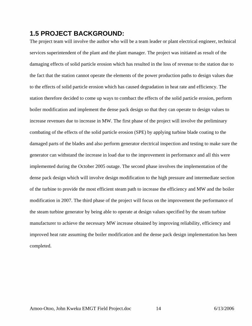
1.5 PROJECT BACKGROUND: The project team will involve the author who will be a team leader or plant electrical engineer, technical services superintendent of the plant and the plant manager. The project was initiated as result of the damaging effects of solid particle erosion which has resulted in the loss of revenue to the station due to the fact that the station cannot operate the elements of the power production paths to design values due to the effects of solid particle erosion which has caused degradation in heat rate and efficiency. The station therefore decided to come up ways to combact the effects of the solid particle erosion, perform boiler modification and implement the dense pack design so that they can operate to design values to increase revenues due to increase in MW. The first phase of the project will involve the preliminary combating of the effects of the solid particle erosion (SPE) by applying turbine blade coating to the damaged parts of the blades and also perform generator electrical inspection and testing to make sure the generator can withstand the increase in load due to the improvement in performance and all this were implemented during the October 2005 outage. The second phase involves the implementation of the dense pack design which will involve design modification to the high pressure and intermediate section of the turbine to provide the most efficient steam path to increase the efficiency and MW and the boiler modification in 2007. The third phase of the project will focus on the improvement the performance of the steam turbine generator by being able to operate at design values specified by the steam turbine manufacturer to achieve the necessary MW increase obtained by improving reliability, efficiency and improved heat rate assuming the boiler modification and the dense pack design implementation has been completed.

Amoo-Otoo, John Kweku EMGT Field Project.doc 15 6/13/2006
1.6 ABC ENERGY RESOURCES-XYZ POWER PLANT The ABC station was originally owned by XYZ Energy Generating and subsequently by ABC Energy Generating. The station is located near ABC, Illinois, and west of the Illinois River. ABC Power Station consist of one steam turbine with a net generating rating of 366MW. The unit began commercial operation in 1976. Coal is received by rail and limestone by rail by rail or truck. Rail cars are unloaded in a rotary car dumper at a rate of 20-25 cars per hour. A 30 day supply of coal is maintained in the on- site storage area. The fly ash and bottom ash is collected and sluiced to ash ponds. The unit start-up power is supplied as back-feed from the grid via the cranker transformer. An emergency diesel generator provides power for emergency shutdown.
ABC Station Characteristic Summary Net Capacity 366MW Steam Turbine Type Tandem Compound, Double Flow Manufacturer General Electric Turbine Inlet Pressure,psig 2400Turbine Inlet Temperature,F 1005/1005 Generator Manufacturer General Electric Cooling Gas Hydrogen Rating MVA 490Boiler Manufacturer Riley Stoker Type Front Fired, Natural Circulation Rated Steam flow 3,000,000 Primary fuel Coal Secondary Fuel Fuel Oil

Amoo-Otoo, John Kweku EMGT Field Project.doc 16 6/13/2006
2.0 LITERATURE REVIEW The following are the books and EPRI published reports used in the research and execution of this project. A. Thomas McCloskey, Barry Dooley “Solid Particle Erosion Technology Assessment” EPRI Research Project 1885 and Report TR-103552 1993 This report was published by EPRI (Electrical Power Research Institute) by project managers Thomas McCloskey and Barry Dooley and had the final report completed by December 1993. The report summarizes how the effects of solid particle erosion has cost American utilities billions of dollars in steam turbine operation, maintenance, and reliability penalties. The reports also indicates how the problem effects of solid particle erosion has been recognized, awareness programs being developed and comprehensive solutions being developed to combat the effects. The reports summarizes the severity and extent of the solid particle erosion problem and define the solutions to mitigate the effects of the solid particle erosion. Below are some of the solutions proposed outlined in this report which is pertinent to this project.
2.1 PROPOSED SOLUTIONS 2.1.1 BOILER CHEMICAL CLEANING The benefits of chemical cleaning in reducing boiler tube failures by removing tube deposits and reducing the thickness of the oxide scale was also investigated since the boiler design includes provisions for chemical cleaning. This is a widely used solution and it involve periodic cleaning of affected boiler and steam piping surfaces to remove operationally formed oxide scale from the internal surfaces of the main steam line. This will be done by flushing with a chemical solvent
2.1.2 COATINGS FOR SPE RESISTANCE The erosion rate for the ductile materials used in turbine steam paths depends strongly on the particle impact angle. General Electric recommended the spraying of plasma on steam buckets. The buckets

Amoo-Otoo, John Kweku EMGT Field Project.doc 17 6/13/2006
were plasma sprayed with tungsten carbide coating to impart SPE resistance. Solutions that does not involve the removal of erosive particles from the steam but rather involve protecting turbine components from the particles. The erosion rate is a function of the particle volume fraction in the steam, the particle diameter, the particle velocity and the angle of attack. Some of the advantages of the plasma spray are 1) Most of these coating techniques require no special or complicated heat treatment process 2) Service exposed and damages coatings can be repaired locally recoating the entire component 3) Thermally-sprayed coatings can be applied up to a certain range of thickness within a reasonable cost and time limitation. The disadvantages are 1) Overlay coatings are usually brittle 2) Too thick a coating can change the blade frequency
2.1.3 CHROMIZED LAYER The chromizing process was proposed by General Electric and is the metallurgical alloying of chromium to the surfaces of the boiler components. The process provides a distinctive layer that consist of an outer, thin chromium rich carbide adjacent to a thicker chromium diffused zone. The principal sources of particles causing turbine erosion is the exfoliation of the oxides formed by the reaction of the steam with steam generator materials. The function of the chromate treatment is to retard the rate of oxidation and stabilize the scale to prevent exfoliation for a much longer period of time. The process will involve chromating the inner surface of the existing boiler tubes after they have been chemically cleaned. Chromate treatment will retard the oxidation rate and stabilize the scale formed and prevent the exfoliation for a much longer period of time.

Amoo-Otoo, John Kweku EMGT Field Project.doc 18 6/13/2006
2.1.3. PLASMA SPRAY COATINGS The functions of coatings on steam turbines components are strictly protective. They shield the components for exfoliated particles which reach the turbine. The most commonly used coating involves the application of chromium carbide coating to turbine parts such as diaphragms and rotor blades.
2.1.4. DIFFUSION ALLOYING The process involves exposure of the part to be coated to a pack cementation process and subsequent heat treatment and is useful for coating turbine parts.
2.1.5. DESIGN MODIFICATION FOR SPE RESISTANCE It is generally agreed that the geometry of the path which the steam follows through a turbine can make a significant difference in the amount of SPE experienced. General Electric new nozzle design involves a new nozzle partition profile in which the partitions are slanted to minimize particle impact and to lower the particle impact impingement incident angles on the nozzle pressure side trailing edge. The fewer number of impacts combined with lower impact incidence angles significantly reduces the erosion potential. General Electric has also discovered that increasing the axial spacing between nozzles and buckets reduce the rebounding of particles as they pass through the turbine particularly the reheat stages and it allows more time for the steam to accelerate the particle as they pass from the nozzle to the blades. As a result, they are less likely to rebound and the elimination of particle rebounding reduces the erosion of diaphragms and blades. B. Black and Veatch “Power Plant Engineering”2003 by Kluwer Academic Publishers This book is a book written by a group of authors at Black and Veatch Corporation. This book describes the various aspects of the power generation process. It also discusses the theory and practical applications of the major areas of the power plant from design processes to thermal heat balances. The book further defines and analyzes the features of various plant systems and major components. Chapter

Amoo-Otoo, John Kweku EMGT Field Project.doc 19 6/13/2006
5 focuses on the how coal is fed from the storage, pulverized to a powder and blown into the steam generator. Within the steam generator the pulverized coal is mixed with air and combusted to produce steam. Chapter 7 discusses the steam generator system and component design. Chapter 8 further focuses on how the steam turbine converts the steam thermal energy to rotating mechanical energy and the generator which is coupled to steam turbine, converts the mechanical energy to electrical energy. Chapter 13 describes how the steam cycle performance is affected by numerous design and operating parameters such as main steam and reheat steam pressure and temperature, steam turbine back pressure, number of feedwater heaters, superheater and reheat temperature flows and the use of a steam turbine generator thermal kit. Below is some of the pertinent information applicable to this project.
2.2 VARIOUS EQUIPMENT COMPONENT THAT CONSTITUTES THE POWER PRODUCTION PROCESS
2.2.1 POWER TRANSFORMER: Power transformers are used to raise or lower the voltage in electric power systems and also to move electrical energy in an efficient manner. The power transformer makes it possible to use the optimum voltage of the transformer itself. A transformer consists of two or more coils (windings) which are linked. If one of the windings-the primary- is connected to an alternating current. An alternating magnetic field will be produced in the coil. The magnitude of the field is determined by the number of turns, magnitude of the alternating current, and the permeability of the material within the winding.
2.2.2 GENERATOR: Generator sizes range from small 1 or 2 KW size to the large 1,000MW variety. All have the same function that is to convert mechanical energy in an efficient manner as possible. Some of the parts of the Generator is the stator which is the stationary portion and contains the stator windings which are connected to the electrical power systems. The stator windings in a three phase machine consist of three identical coils of conductor wound into the face of high-permeability steel laminations. Each coil is

Amoo-Otoo, John Kweku EMGT Field Project.doc 20 6/13/2006
wound longitudinal at 120 mechanical degree intervals around the circumference of the stator so that when the two pole electromagnet is rotated inside the stator, voltages are produced which reach their maximum value at 120 electrical degrees. The loading capacity of a generator is limited by the saturation flux density of the iron stator magnetic laminations, the ability of the conductors to remove heat from the machine, and the mechanical strength of the windings to resist the electromagnetic forces imposed on them by the rotating magnetic field and induced currents. Stator iron flux density is controlled by the selection of the material to be used in the stator laminations. As machine size increases, air cooling becomes impractical because of the diminishing returns caused by the windage loss in the machine and the resultant volume of air required to circulate through machine in order to cool the machine. In such cases hydrogen gas is used to cool the machine. Hydrogen offers a very high coefficient of heat capacity and a very low specific gravity. Therefore hydrogen conducts heat away from the stator at high loads while producing low windage losses. In addition, hydrogen will not support combustion if the purity is maintained above 95% and it is not explosive if the purity is maintained above75%. In very large generators or machines, the stator conductors may be hollow to allow pure de-ionized water to be circulated in the windings to also assist in removing heat. This water must remain without conductive contaminants to maintain the insulation value of the generator. The second part is the rotating piece which is the rotor and it carries the rotating field. Most large steam turbines drives rotate at 3600rpm for 60Hz systems therefore the rotor in such a generator would be a two pole electromagnet, usually of cylindrical design. Direct Current is introduced into the rotating piece by means of slip rings and sliding brushes. The d.c current then produces the electromagnetic field which is used to change mechanical energy to electrical energy in the stator. By varying the amount of current in the field, the voltage on the terminals of the generator can be varied. The generator must be capable of producing the maximum peak load power requirement established by the plant. Generator Power ratings are given as the total power that is the vectorial sum of the active or

Amoo-Otoo, John Kweku EMGT Field Project.doc 21 6/13/2006
the real power KW and the reactive power-Kilovars. The generator nameplate rating is specified as net terminal KVA with hydrogen pressure.
2.2.3 STATOR: The stator consists of stator core and stator windings. The stator core has two major functions: to support the stator winding coils and to provide the flux path that links the stator coils and the rotating magnetic field. The stator core is made of many high-permeability, low loss silicon steel laminations. These Laminations are coated on both sides with high temperature insulation. The laminations minimize the Transformer type losses caused by eddy currents. Hydrogen gas flowing through the ventilation passages between the lamination groups removes the heat generated in the stator. The stator winding provides the generator output voltage and current.
2.2.4 ROTOR: The rotor provides the magnetic field of the generator. The rotor shaft is one-piece, high strength forging. The machine shaft contains the winding slots, end turn ventilation slots, pole face slotting, bearing journals and the couplings. The rotor winding is a multiple-turn, continuous-series winding. The winding is connected to the exciter through slip rings to receive power for the generation of the magnetic flux.
2.2.5 BUS DUCT: Large generators are normally connected to the low-voltage terminals of the generator step-up transformer with bus duct. The isolated bus duct is one in which each phase conductor is enclosed by an individual metal housing separated from adjacent conductor housings by air space. The conductors in segregated and isolated phase bus are normally made of aluminum although copper conductors are occasionally used.

2.2.6 ELECTRICAL ENERGY GENERATION: The rotational mechanical is converted to electrical energy in the generator by the rotation of the rotor’s magnetic field. The rotation of the turbine turns the rotor of the generator. The generator rotor consist of a steel forging with slots for conductors that are called field windings. An electrical direct current is passed through the windings, causing a magnetic field to be formed in the rotor. This magnetic field is rotated by the turbine. The rotor is surrounded by the generator stator that includes copper conductors. The magnetic field of the rotor passes through the stator, setting electrons in the stator conductor in motion. As the rotor’s north pole passes through the stator conductors, the current floes in one direction. When the south pole of the rotor’s magnetic field passes through the same conductor, the current flows in the opposite direction. This type of electrical current is called alternating current.
2.2.6.1 UNIT STEAM TURBINE GENERATOR MW OUTPUT AND VOLTAGE REGULATION
STEAM TURBINE
GENERATOR
STEP-UP XFMR
SYSTEM VOLTAGE
MW
MVARS/EXCITER
MVARS TO SUPPORT SYSTEM VOLTAGE AND INDUCTIVE LOADS
Governor control MW output through control valves in steam chest
Amoo-Otoo, John Kweku EMGT Field Project.doc 22 6/13/2006

Amoo-Otoo, John Kweku EMGT Field Project.doc 23 6/13/2006
2.2.7 STEAM TURBINE GENERATORS: The operation of the steam turbine generator involve the expansion of steam through numerous stages causing the turbine rotor to turn the generator. The thermal energy of the steam is converted to mechanical energy by expanding the steam through the turbine. The steam turbine generator is the primary power conversion component of the power plants. The function of the steam turbine generator is to convert the thermal energy of the steam from the steam generator to electrical energy.
2.2.8 VALVES: The following are the valves associated with the steam turbine 2.2.8.1 Main Steam Stop (Throttle) Valves: The steam from the steam generator flows to the main steam stop or throttling valves. The primary function of the stop valves is to provide is to provide back-up protection for the steam turbine during turbine generator trips in the event the main steam control valves do not close. A secondary function of the stop valves are to provide steam throttling control during start-up. 2.2.8.2 Main Steam Control Valves: The steam flows from the stop valves to the main steam control or governor valves. The primary function of the control valves is to regulate the steam flow to the turbine and thus control the power output of the steam turbine generator.
2.2.8.3 Reheat Stop and Intercept Valves: The steam exhausted from the high-pressure turbine flows through the cold reheats lines to the reheater in the steam generator. The reheated steam then flows through the hot reheat piping to the reheat stop and intercept valves. The reheat stop and intercept valves function similarly to the main and control valves. The reheat stop valves offer back-up protection for the steam turbine in the event of a unit trip and failure of the intercept valves. The intercept valves control unit speed during shutdowns and on large load swings and protect against destructive overspeeds. The need for these valves is the large amount of energy available in the steam present in the high pressure turbine, the hot and cold reheat lines, and the

Amoo-Otoo, John Kweku EMGT Field Project.doc 24 6/13/2006
reheater.
2.2.8.4 Turbine Stationary Parts: 2.2.8.4.1 High-Pressure-Intermediate-Pressure Turbine The steam flows to the high-pressure and intermediate pressure turbine sections are high pressure, high temperature flows. Outer and inner cylinders or casings contain the steam. The cylinders are castings. The outer cylinder acts like the overall pressure vessel and provides support for the inner parts. The inner cylinder also acts as a pressure barrier and supports the blade ring. The blade rings supports the stationary blades. The stationary blades are directly in the steam path of the rotating blades. The stationary blades have a pressure drop, increasing the steam velocities and directing the steam to the next row of rotating blades. The end of the stationary blades adjacent to the rotor has a labyrinth-type seal to minimize steam leakages between the rotor and the stationary blade. The blade ring is called a nozzle diaphragm. The steam enters the high-pressure turbine from the main steam control valves. The steam enters the turbine nozzle chamber, expands through the nozzle block, strikes the control stage blades, is turned 180 degrees and flows to the remainder of the high pressure turbine stages. Each nozzle chamber is supplied steam from one control valve. The first set of stationary blades that are of special design are nozzle blocks. The seals are labyrinth-type with backing springs to ensure tight clearances between the seal and the rotating shaft. 2.2.8.4.2 Low-Pressure Turbine Like the high-pressure-intermediate pressure turbine, the low pressure turbine has an outer cylinder, inner cylinder, blade rings, and casing seals. The steam temperature in the low-pressure turbine drops to 600 to 700 degree farhenheight during its expansion through the low-pressure turbine. The casing to shaft seals prevent leakage of air into the condenser.

Amoo-Otoo, John Kweku EMGT Field Project.doc 25 6/13/2006
2.2.9 STEAM GENERATOR The steam generator in a power plant converts the chemical energy in the fuel to heat energy in the water and steam. The efficient, complete combustion of fuel is so important in the efficient conversion of the chemical energy of fuel to the energy of high pressure and temperature steam. There are two sides of the steam generator, the combustion side and the steam/water side. The large utility boiler is the waterwall type. A waterwall boiler is a box whose walls are made up of tubes through which water flows. The fuel is burnt in the furnace. Heat is transfered to the water that flows through the tubes, and thus steam is generated.
2.2.9.1 Steam Drum The steam drum serves two purposes in a boiler: it is a header for distributing water to the down comers and secondly it separates the steam from the water. The steam leaves the drum and flows to the superheater and the turbine. The steam drum runs the entire length of the boiler and has connections for the downcomers, waterwall risers, continuous blowdown and chemical addition. The inlets to the steam drum includes the following connections feed water, riser or generating tubes and chemical feed. The steam drum also has continuous blowdown which allows chemicals that are injected directly into the steam drum and other dissolved solids that may enter the boiler that do not leave with the steam. Blowdown removes dissolved and suspended solids. It also has a steam outlet that is normally a series of tubes at the top of the drum that carry steam to the superheater.
2.2.9.2 Superheaters and Reheater There are two types of superheaters, the convection type and radiant type. Either of these superheaters can be further described by its orientation in the furnace or gas path by whether it is a primary or secondary superheater. Radiant superheaters are positioned above the boiler furnace at the front of the boiler and are the first superheaters that the gases contact. They receive most of their heat from radiation given off by the fire ball. Convection superheaters are located are located in the backpass of the boiler

Amoo-Otoo, John Kweku EMGT Field Project.doc 26 6/13/2006
gas path, therefore receiving heat from the flow of hot gases over the rubes. The orientation of the superheaters are Pendant which describes a superheater that is hung or suspended in the gas path. The hot gases flow between the tubes in the tube bundle. Platten superheaters describes a radiant pendant superheater that is suspended through the furnace roof but oriented parallel to the sidewalls of the furnace.
2.3 FUEL ANALYSIS The properties of fuels burned in steam generators are normally expressed in two different ways, proximate and ultimate analysis. The proximate analysis is useful in predicting fuel behavior; the ultimate analysis which provides an elemental composition of a fuel.
2.3.1 Proximate Analysis: The proximate analysis of a coal gives percentages by weight of moisture, volatile matter, fixed carbon, ash and the heating value. The amount of moisture and ash indicates the difficulty in handling and burning the coal. Fixed carbon is an indication of how hard the coal is to pulverize. Moisture is the water contained in the coal. Wet coal affects the plant in three ways. Fist it can clog the handling of conveyors and chutes that affect that deliver the coal to the crushers and pulverizers, secondly the wet coal can clog the feeders, interrupting the flow to the pulverizers. Two kinds of moisture in coal are surface moisture and inherent moisture. Surface moisture is water that is on the surface of the coal. Fixed carbon is the combustible matter left after the volatile matter in coal is burnt. Coals with a high percentage of fixed carbon usually burn more slowly because the carbon burns slower than volatiles. Ash is the material left after all the combustible material in the coal is burned.

Amoo-Otoo, John Kweku EMGT Field Project.doc 27 6/13/2006
2.3.2 Ultimate Analysis: The ultimate analysis provides information on the chemical composition of a fuel. The carbon reported in the ultimate analysis includes all the carbon in the volatile matter and fixed carbon portions of the fuel. The hydrogen reported in the ultimate analysis contains all the elemental hydrogen in the fuel. The Nitrogen reported includes all the elemental nitrogen in the fuel. The oxygen reported includes all the elemental oxygen in the fuel. The moisture, ash and sulfur content given in the analysis includes all the elemental oxygen in the fuel. Sulfur is an undesirable part of coal. When coal is burned, the sulfur burns and forms sulfur dioxide and sulfur trioxide.
2.4 CLOSED FEEDWATER HEATER THEORY The function of feedwater heaters in the power plant cycle is to heat feedwater, using extraction steam from the turbine, before it enters the economizer. Heating the feedwater serves two purposes: it reduces the thermal shock caused by the cold feedwater, and much more importantly it improves plant efficiency The most simple closed feedwater heater is a shell and tube heat exchange that is supplied with steam at saturated conditions. Many feedwater heaters, especially high-pressure heaters are fed with steam having some superheat. The feedwater heater may be built with a separate desuperheating section. The extraction steam enters the desuperheating section where, by design, it is cooled by saturation temperature. The now saturated steam then flows from the desuperheating section to the condensing section. The condensate from the condensate section the flows into the drain cooler where it is subcooled. The feedwater then passes in succession from the drain cooler section and finally to the desuperheater section and finally to the desuperheating section.

Amoo-Otoo, John Kweku EMGT Field Project.doc 28 6/13/2006
2.5 CONDENSERS Surface condensers are heat exchangers that are essential to the efficient operation of the power plant. They serve three basic functions in the plant operation, providing a high vacuum environment where the turbine exhaust steam can be condensed, deaerating the condensate and providing a collection point for the condensate so that it can be returned to the steam generator. Steam enters the condenser from the turbine-generator low pressure exhaust. At this point, the steam has a rather high velocity. While it is desirable for the steam to have a certain amount of velocity so that some of the steam penetrates to the center of the tube bundle, the moisture in the steam can erode the surface of the condenser tubes, eventually causing tube leaks, if it is allowed to directly strike them. Therefore baffle plates are placed at the top of the condenser is some designs to prevent steam flow from impinging on the tubes and to redirect the steam flow for even more heat transfer throughout the tube bundle.
2.6 AIR HEATER Air heaters are major components that have great influence on boiler efficiency. Their effect on boiler efficiency is reflected primarily in the flue gas exit temperature. Generally the flue gas exit temperature tends to increase as air heater efficiency decreases. Flue gas exit temperature may be decreased by excessive leakage of combustion air into the flue gas in the air heaters. Flue gas temperature is also affected by the amount of the excess air. The following are the performance factors associated with the air heater; air heater leakage, gas side efficiency, flue gas exit temperature, x-ratio and air side and gas side pressure drops. C. General Physics “Troubleshooting and Analyzing Coal-fired Boiler Efficiency Problems” This book was written by General Physics Corporation after realizing that the accurate determination of boiler efficiency presents many challenges to the power plant performance engineer. This book covers the major areas that impact boiler efficiency, operational limits of pressure and temperature that must be followed critical to avoid damage to an equipment. It focuses on the knowledge the performance engineer needed to accurately determine boiler efficiency and also the determine the root causes of

Amoo-Otoo, John Kweku EMGT Field Project.doc 29 6/13/2006
boiler inefficiency. The book also focuses and discusses on the major energy losses in the boiler and the limiting factors that affect the ability to operate a boiler at its best efficiency. Below are some of the literature from the book that is applicable to this project.
2.7 OPERATIONAL THEORY AND LIMITATION FACTORS The function of the boiler is to transfer as much heat as possible from the burning fuel to the boiling water and steam circuits in a way that provides the required flow of steam to the turbine at the proper conditions of temperature and pressure. Any heat energy not transferred to the water and steam represents a boiler loss. The major energy losses in a coal-fired boiler are flue gas losses, unburned fuel loss, and radiant heat loss.
2.7.1 Flue Gas Losses: One of the major energy losses associated with the operation of the boiler is the heat contained in the flue gas discharged from the air heaters and eventually lost up the stack: It is possible to recover the maximum amount of heat energy from the flue gases by cooling them down in the air heater to a temperature very close to the incoming combustion air temperature. However, such a design leads to condensation of acid and water on the flue gas side of the air heater because of the water vapor and sulfur oxides present in the flue gas. This leads corrosion damage of ductwork and downstream components and plugging of the air heater. Flue gas losses also referred to as stack losses. The dry flue gas loss is a significant proportion of the boiler losses. To maintain maximum boiler efficiency, it is essential that the combustion of air enter the boiler with a proper air/fuel balance at each burner in service. In balanced drafts air-in-leakage through the boiler results in fooling the oxygen analyzers in the flue gas ducts, triggering a reduction in total air flow to the burners from the forced draft. This typically leads to an increase in the unburned carbon loss and creates other problems such as excessive slagging, liquid phase corrosion of the superheater/reheater tubes and burner coking. A boiler furnace is designed to absorb a specific percentage of the total heat released in the furnace. The remaining heat not absorbed

Amoo-Otoo, John Kweku EMGT Field Project.doc 30 6/13/2006
in the furnace enters the convection pass and is eventually absorbed in the superheater, reheater, economizer, and air heater sections. Slag accumulations on the furnace walls reduce the heat absorption and result in more heat being passed into the convection pass. As slag accumulates in the furnace, steam generation in the water walls decreases with a resultant increase in fuel and airflows to re-establish the necessary steam production. A loss of thermal efficiency in the turbine cycle results from the increased desuperheating sprays, particularly the reheat sprays, and leads to decreased electric output even when the energy flow rate into the turbine cycle. Moisture losses include the loss due to inherent and surface moisture in the fuel, the moisture loss due to combustion of hydrogen, and a small loss due to moisture in the combustion air. The significant losses here are the ones due to moisture in the fuel and the combustion of hydrogen. In addition to carrying away heat up the stack, moisture in the flue gas limits the temperature to which the flue gases may be cooled due to corrosion considerations in the cold end of the air heater, ductwork, ID fans and precipitator.
2.7.2 Unburned Fuel Loss: In a typical pulverized coal-fired unit, approximately 4% of the ash consists of unburned carbon. This carbon has the potential to undergo combustion in the furnace and release thermal energy. In coal fired units, the unburned combustible loss includes the unburned constituents in the ash hopper refuse as well as in the flue dust. Carbon in the ash has a direct impact on boiler efficiency and therefore unit heat rate. The amount of unburned combustible in the ash is a measure of the effectiveness of the combustion process in general and the pulverizers/burners in particular.

Amoo-Otoo, John Kweku EMGT Field Project.doc 31 6/13/2006
2.7.3 Radiant Heat Losses: The heat loss to the surroundings by radiation and cold face temperature of the insulation increases. Typically for a properly designed and well-insulated boiler, radiant heat loss can be less than 0.25%.
2.7.4 Limiting Factors: Several factors limit the ability to operate a boiler at its best efficiency or even the desirability to do so. These factors include safety concerns, tradeoffs with turbine cycle-related. Specific operational concerns are 1) Maximum SH and RH steam temperatures 2) Minimum allowable excess oxygen 3)Minimum allowable air heater average cold end temperature and 4) Minimum allowable exit Gas (air heater outlet) temperature.
2.7.4.1 Superheat and Reheat Steam Temperature: While an increase in steam temperature has a direct beneficial impact on turbine cycle heat rate and there is no benefit to boiler efficiency and certainly detrimental effect on reliability. An increased main steam temperature (Reheat Turbines) actually decreases steam flow through the turbine as well as steam generation. Although an increased Superheat temperature above design has slight beneficial impact on turbine cycle heat rate, its detrimental effect on generation and tube life overrides any benefit from operating at higher than design superheat steam temperatures.
2.7.4.2 Excess Oxygen: Operating with low excess oxygen values results in several detrimental values effects on the boiler equipment and materials. Primarily, low excess oxygen levels can lead to unstable combustion with the potential for “puffs” and resultant damage to waterwalls and other areas of the boiler. Low excess oxygen operation also generally results in poorer combustion with increased losses in efficiency due to high carbon monoxide levels in the flue gas as well as higher percentages of carbon in the ash. In addition to the more obvious reasons for not operating at low excess oxygen, other damaging

Amoo-Otoo, John Kweku EMGT Field Project.doc 32 6/13/2006
or potentially damaging conditions exist when attempting to improve upon boiler efficiency by operating at marginally low oxygen level. These include 1) Increased slagging of waterwalls and superheater sections 2) Increased corrosion rates of superheater and reheater tubes 3) Burner “coking” and nozzle damage and 4) Electrostatic precipitator fires.
2.7.4.3 Increased Slagging: As furnace excess oxygen levels are reduced, the potential for creating a reducing atmosphere along the waterwalls increases. Many coals, particularly those with a high iron content in the ash, have significantly lower fusion temperature. The lowered fusion temperature results in ash deposits becoming “plastic”. This increased slagging results in poor furnace heat transfer, a potential for large clinker formations and impact damage to lower slope furnace tubes when they fall, convection pass plugging and liquid phase corrosion.
2.7.4.4 Superheater and Reheater Tube corrosion: All bituminous coals contain enough sulfur and alkali metals to produce corrosive ash deposits, particularly those with sulfur and chlorine contents. Investigation have found that when dry, the sulfates formed have little corrosive activity. However, when semi-molten, they corrode most alloy steel used in superheater and reheater tube construction.
2.7.4.5 Burner Damage: Proper combustion of fuel at the burner front is dependent upon a number variables including the velocity of combustion air. As excess oxygen is decreased, the mass flow rate and velocity of combustion air decrease accordingly.

Amoo-Otoo, John Kweku EMGT Field Project.doc 33 6/13/2006
2.7.4.6 Electrostatic Precipitator Fires (ESP): As previously, operating with low excess oxygen levels typically results in the formation of high levels of carbon dioxide. On the cold-side precipitators, the carbon monoxide gases mix with leakage air that flows across the air heater seals as well as ESP insulator compartment purge air, to form a highly combustible mixture.
2.7.4.7 Minimum Allowable Average Cold End Temperatures (ACET): There are two operational limitations to how much the flue gas can be cooled. The first limitation is the air heater ACET, the second is the due point of the flue gas. The final temperature of the baskets entering the gas side is highly dependent upon the air inlet temperature to the air heater. If the flue gas is cooled below the acid dew point in the intermediate-section the air heater cleaning systems cannot reach the deposits to remove them, therefore air heater plugging occurs.
2.7.4.8 Minimum Allowable Exit Gas Temperatures: When the flue gas cools below its acid dew point, corrosive acids are formed. These acids, if allowed to form, attack the flue gas ductwork, ESP’s and ID fans. D. George Yeboah “835-Field Project-Developing an implementation plan for Turbine Generator Stator Rewind” Spring 2003 This report was a field project written by George Yeboah of Kansas City Power and Light. Chapter 1 section 8 of this field project focuses on the project charter which is a very critical piece for the successful implementation of this project. The section further discusses the selection of the project manager and project team leaders which is also critical to the success of this project. Chapter 2 further focuses on the project planning which involves creating a project team, prepare budget, prepare work breakdown structure, prepare project schedule, prepare communication plan and schedule kick off meeting. All these elements are vital to the successful implementation of a project. Chapter 3 section 2 focuses on the project execution and control and a further discussion on the section describes how the cost, schedule and cost control can be executed and controlled. Section 4 of the chapter discusses the

Amoo-Otoo, John Kweku EMGT Field Project.doc 34 6/13/2006
implementation of progress meetings and further describes the different types of meetings needed for a project like this. Section 5 of the chapter describes how the risk associated with a project can be identified and managed during the course of the project. Chapter 4 of the field project paper describes how the formal acceptance of a project can be done, release team members and file historical records of the project. The section further describes how to document lessons learned on the project.

DETAIL OF “THE PROBLEM” OR AREA TO BE INVESTIGATED
PROCEDURE AND METHODOLOGY
3.0 ASSIGNMENT OF PROJECT MANAGER AND TEAM LEADERS The project manager was the plant manager and was responsible for approving the budget and the
manpower needed for this project. The project team leader was the technical superintendent for the plant, he was responsible for providing the necessary data for past heat rate testing. The project team leader for the Generator Mr. Engineering, he was responsible for preparing the project scope, project schedule and the manpower needed for this project.
PROJECT SPONSOR
PLANT MANAGER
TECHNICAL SUPT PROJECT TM LDR
The project sponsor was Mr. XXXX in upper management and will be the liaison between the project team and upper management.
Amoo-Otoo, John Kweku EMGT Field Project.doc 35 6/13/2006

Amoo-Otoo, John Kweku EMGT Field Project.doc 36 6/13/2006
3.1 GOALS AND OBJECTIVES The objectives of the project team was to find out how the performance of the unit can be improved in terms of increase in MW assuming the dense pack project which will involve modification work of the High Pressure and Intermediate Pressure sections of the turbine to provide the most efficient path for steam and also the boiler modifications project which will involve the replacement of the boiler tubes, superheater and reheater tubes have been completed. The project team also performed the electrical testing and inspection of the generator during the outage in October 2005 to make sure the generator can handle the increase in MW due to performance improvement.
3.2 PROJECT PLANNING Any one working on the project was asked through e-mail to attend project meetings. Every one was asked to identify the task that will be involved in each scope to be included in the planning and the objective of the project planning committee was to gather enough information to support the goals and objectives of the project and to limit risks and minimize scope changes. The goal of the project was to get a better understanding of the project, eliminate most uncertainty tied to projects, get team members to know each other and also strengthen communications between them, avoid future problems associated with the project and provide monitoring and controlling.

3.3 CREAT PROJECT TEAM The diagram below shows the project team and the responsibilities of each person that was created. Each project team member had and executed the skills need for the completion of the project.
PROJECT SPONSOR
PLANT MANAGER
TECHNICAL SUPT PLANT ENGINEER
3.5 PREPARE BUDGET Preparing the budget involved reviewing the proposal from the vendors and after review it was submitted to the plant technical superintendent with a project justification this includes a detail cost, list of materials and labor report for approval. After the package was reviewed, an authorization was given to generate an electronic bill of material (EBOM) for a purchase order to be created for the vendors and contractors to be paid when services were completed and equipment installation tested to be in operable state.
Amoo-Otoo, John Kweku EMGT Field Project.doc 37 6/13/2006

Amoo-Otoo, John Kweku EMGT Field Project.doc 38 6/13/2006
Below is an excel spreadsheet of the budget estimate: Line Item Project Management/Engineering/Contract Administration $300,000 Operations Support $7,000 Generator Open $200,000 Generator Close $200,000 Crane Operator $35,000 Electrician Support $5,000 Mechanic Support $5,000 Generator Stator Inspection and Testing $100,000 Re-wedge of generator $500,000 Rotor inspection and testing $50,000 Alterrex Exciter stator inspection and testing $15,000 Alterrex Exciter rotor inspection and testing $10,000 Dovetail inspection $5,000 Steam Turbine Outage inspection, testing and refurbishment $500,000 Pressure Decay/Vacuum Decay test $20,000 Contingency $10,000 TOTAL $1,962,000
3.6 PREPARE PROJECT SCHEDULE The generator and exciter inspection started in October 2005 during the fall outage and the outage was scheduled for 10 weeks. Work was completed by that time for start up to commence 10th of December, 2005. Each contractor on site was responsible for managing his own labor force and each contractor was supposed to submit to the project team leader weekly milestones. Daily progress report was logged into the turbine generator outage schedule and contractor outage reports was submitted to the team leader two weeks at the end of the inspection and testing period. Below is the project schedule for the execution of the project:

Amoo-Otoo, John Kweku EMGT Field Project.doc 39 6/13/2006

Amoo-Otoo, John Kweku EMGT Field Project.doc 40 6/13/2006 Amoo-Otoo, John Kweku EMGT Field Project.doc 40 6/13/2006