Embed Size (px)
Citation preview

EMG-Based Teleoperation and Manipulation with the DLR LWR-III
Jorn Vogel, Claudio Castellini and Patrick van der Smagt
Abstract— In this paper we describe and practically demon-strate a robotic arm/hand system that is controlled in real-time in 6D Cartesian space through measured human mus-cular activity. The soft-robotics control architecture of therobotic system ensures safe physical human robot interactionas well as stable behaviour while operating in an unstruc-tured environment. Muscular control is realised via surfaceelectromyography, a non-invasive and simple way to gatherhuman muscular activity from the skin. A standard supervisedmachine learning system is used to create a map from muscleactivity to hand position, orientation and grasping force whichthen can be evaluated in real time—the existence of such amap is guaranteed by gravity compensation and low-speedmovement. No kinematic or dynamic model of the human armis necessary, which makes the system quickly adaptable toanyone. Numerical validation shows that the system achievesgood movement precision. Live evaluation and demonstration ofthe system during a robotic trade fair is reported and confirmsthe validity of the approach, which has potential applicationsin muscle-disorder rehabilitation or in teleoperation where aclose-range, safe master/slave interaction is required, and/orwhen optical/magnetic position tracking cannot be enforced.
I. INTRODUCTION
Surface electromyography (sEMG) for prosthetic handcontrol has since a long time been used, even in the com-mercial setting, for the control of prosthetic hands, albeit thecontrol is mostly limited to one or two degrees of freedomand predefined hand postures. sEMG is a totally non-invasiveand relatively cheap technique to measure muscular activity.The obtained signal is strongly and stably related to the forceexerted by the measured muscle(s) thanks to the electricalactivity of ensembles of motor units. The signal is noisy, butthe fact that many hundreds of motor units combine togethermakes it is relatively insensitive to small influences, to thepoint that sEMG is widely demostrated in literature [1], [2],[3], [4], [5] as an excellent means to control dexterous handprostheses.
The use of EMG for copying arm movement howeveris a totally different problem: in this case, the humanskeletomuscular system does not exert a certain force tohold or grasp an object; rather, muscles are activated tomove an arm to or track a desired Cartesian position. Inmost finger movement settings, the precise finger position issecondary to the exerted force; in arm movement, it is ratherthe other way around. The nature of the sEMG signal maytherefore indicate its inapplicability for this task; nonetheless,
This work is partially supported by the European FP7-Project THE HandEmbodied (FP7-IST-248257).
The authors are with the Institute of Robotics and Mechatron-ics, German Aerospace Center, D-82234 Oberpfaffenhofen, Germany{joern.vogel,claudio.castellini,smagt}@dlr.de
Fig. 1. The system during a live demonstration at the Automatica 2010trade fair (www.automatica-munich.com).
interesting results have already been obtained by Artemiadisand Kyriakopoulos [6], [7], [8].
In this work we follow the approach outlined in that work,at the same time lifting some of its limitations. In particular,we address the low number of controlled degrees-of-freedom(3), the low generalisability (a detailed model of the arm ofthe human subject is required) and the use of an industrialrobotic setup, which makes the whole system unsuitablefor close cooperation with human beings. In particular weintroduce a method which matches a 9-dimensional sEMGsignal to a 6-DoF end-effector position plus 1-DoF graspforce. The system, which has been demonstrated online,requires a short training period and can then be used fora prolonged period of time to grasp and move objectsusing the sEMG signal as user interface only. No precisepositioning of the sEMG electrodes, nor any model of thehuman arm is required; the adaptivity of the machine learningapproach used also automatically incorporates compensationfor muscle fatigue, an issue which usually requires non-trivialhandling [7].
Even though the use of the system for precise position tele-operation is limited, the system can be used for rehabilitationpurposes as well as for impedance-controlled, stiffness-basedteleoperation. Furthermore, the current system allows, wherenecessary, for increased accuracy by optimisation of the dataacquisition methods.
II. APPROACH
The system, as described here, was demonstrated at theAutomatica 2010 trade fair in Munich, Germany (see www.
2011 IEEE/RSJ International Conference onIntelligent Robots and SystemsSeptember 25-30, 2011. San Francisco, CA, USA
978-1-61284-455-8/11/$26.00 ©2011 IEEE 672
Fig. 2. An abstract block-diagram representation of the system.
automatica-munich.com). All data presented in this paperwas collected live during the fair.
A picture of the setup in action is visible in Figure 1. Therobot is mounted on a pedestal in a right-arm like posture.A table is placed within the workspace of the robot, to allowthe user to pick up and put down objects; a soft ball is usedto this end. Figure 2 depicts a simplified schematic overviewof the core elements of the system, which consists of twoindependent parts: (1) an EMG-decoder which calculatesCartesian wrist position and orientation as well as graspforce from measured muscle activity, and (2) the DLR Light-Weight Robot III equipped with the DLR-HIT Hand II, whichperforms the decoded motion and grasps. Additionally, avisual tracking system is integrated in the setup in orderto gather the human arm position for training the machinelearning algorithm. As is customary in (supervised) machinelearning, the system operation consists of two phases: thetraining phase, during which an EMG-to-(arm/hand/force)map is built; and the prediction phase, when the map is em-ployed to predict new, previously unseen arm/hand/graspingconfigurations. Before entering the training phase, the subjectis equipped with EMG electrodes to record the muscularactivity.
To build the map, EMG data needs to be acquired, as wellas the real position, orientation and grasp force of the user’shand. Therefore a tracking marker is fixed to the upper sideof the subjects wrist and a rubber ball equipped with forcesensitive resistor is given to the subject (see Figure 3). Oncethe mapping is created, the EMG signals can be used todirectly control the robotic system.
A. Data acquisition
Muscular activity is gathered using nine OttoBock My-oBock 13E200 surface EMG electrodes (www.ottobock.com). The electrodes already provide an amplified, bandpass-filtered and rectified signal, eliminating the need of furtherprocessing onboard the card and/or the computer (theirusefulness was already demonstrated at least in [5], [9]).They are connected to a wireless DAQ card sampling theEMG signals at 100 Hz.
There are three sets of three electrodes. Each set is tiedto a velcro elastic band and roughly uniform spacing of the
Fig. 3. Schematic view of the subject’s arm equipped with the EMGelectrodes, the motion tracking marker and the ball with the FSR on top.
electrodes is visually enforced. The bands are placed on thesubject’s forearm about five centimeters below the elbow, onthe upper arm midway between elbow and shoulder, and onthe shoulder (see Figure 3). No precise positioning of theelectrodes is enforced — this is a great simplification of theoperations and has already been demonstrated effective, evenon amputees [9]. The exerted grasp force is measured withan Interlink Standard 400 FSR force-sensing resistor (seewww.interlinkelectronics.com). The standard amplificationcircuit connected to the FSR returns a voltage signal whichis univocally (logarithmically) related to the force applied toits surface. The above wireless DAQ card is used to digitisethis signal, too, making the whole setup rather easy to wearand take away. The FSR is mounted on a rigid rubber balland the subject is instructed to press it to teach a graspingsignal to the system.
Motion capture is enforced by a Vicon MX (www.vicon.com) motion tracking system. A Vicon “rigid object”consisting of 4 passive markers rigidly connected to oneanother is fixed to the subject’s wrist, and six near-infraredcameras use it to reconstruct the object’s position (x, y, z incentimeters) and orientation (α, β, γ in radians) in real time.The coordinates are relative to an inertial frame set up duringthe Vicon calibration phase. The Vicon has a sampling rateof 200 Hz and generates accordingly a UDP stream of data.
The resulting global data stream (from the Vicon andacquisition card) is received by a standard desktop machineequipped with Matlab and synchronously subsampled at25 Hz, and its moving average over 400 milliseconds (10samples) is evaluated.
B. Machine Learning
After the data acquisition is concluded in the trainingphase, the data set is organised into samples (each sampleconsisting of the 9 values of the EMG electrodes) and 7
673

target values for each sample (the position/orientation of thehand and the grasping force). The resulting (sample, target)pairs are used to train a Support Vector Machine (SVM,see [10]) with Gaussian kernel, with the purpose of buildinga function mapping the EMG values to each target. Oneof the most popular machine learning nowadays, SVMsbuild an approximation of the underlying function as thesum of a finite, and hopefully small, number of Gaussianfunctions, centered on a subset of the training samples calledSupport Vectors. Since in our case every training set wouldconsist of several thousands of samples, we subsampledsequentially the training set in order to have always 750and, later on, 1000 samples available. The training samplesare normalised by subtracting the means and dividing by thestandard deviations, dimension-wise; 10-fold cross-validationand grid-search are conducted in order to find the best SVMhyperparameters. Lastly, a regression model for each targetvalue is created using the 750 or 1000 training samples atonce. These 7 models are the map used in prediction.
C. Robotic Setup
The position and grasp decoding from the EMG signalsis used to control the DLR Light-Weight Robot III (LWRIII) with the DLR-HIT Hand II attached. The LWR III[11] is a seven degree of freedom (7 DoF) robotic armweighing 14kg and able to lift payloads equal to its ownweight. The kinematics of the robotic arm allow to replicatea reasonable large part of the workspace of a human arm.The LWR III is equipped with joint torque sensing in eachjoint, which makes it possible to realise special soft-roboticfeatures such as Cartesian Impedance Control and collisiondetection and reaction [12], [13]. These features are essentialwhen operating in rather unknown environments and physicalcontact with rigid objects needs to be established. The activecompliance of the robot provided by the impedance con-troller copes with these uncertainties and thereby providesstable behaviour of the system. In addition to that, theintegrated torque sensors allow detecting external forces thatappear whenever the robot establishes a physical contact.Depending on the magnitude of the force, the robot can reactwith different strategies and thereby provide safety to theoperator as well as to the robotic hardware (see [14], [15]).All these soft-robotic features are embedded in a human-friendly state-based control architecture [16].
A simplified schematic overview of the robot controlarchitecture is depicted in Figure 4. From the EMG signalsthe humand hand position, orientation, and force is decodedand send to the robot controller via UDP. The UDP streamis received by the high-level task execution layer of therobot controller. This layer operates at a rate of ≈ 100Hzand allows defining complex tasks in a state-based mannerillustrated by the Hybrid task state machine in the blockdiagram. The low-level robot controller runs on a VxWorksrealtime machine at a rate of 1kHz. Communication betweenthe two layers is realised via the ARDNet Interface [17]. Thecore component of the Robot Control kernel is the CartesianImpedance Controller (CIC) which receives a desired Carte-
sian frame as input and calculates the desired joint torques(further details on this control scheme can be found in[12]). As Cartesian human wrist position and orientation aredirectly decoded at a rate of 20Hz it is necessary to employan interpolation to fit the 1ms cycle of the robot controllerand generate a smooth robot motion. Within the interpolationthe maximum achievable translational and rotational velocityis limited to ≤ 0.25m/s and ≤ 0.3rad/s, respectively. Thescaling between human motion and robot motion was kept1:1 in this sets of experiments, though it would easily bepossible to up or downscale the motion when it is exertedby the robotic system. To provide additional safety to theoperator as well as to the robotic hardware, known obstaclesin the workspace, such as the table the user operates on,and the pedestal the robot is mounted on, are internallyrepresented in a virutal environment. This constist of virtualplanar walls which the robot is unable to pass. To achievethis, the virtual walls create a repelling Cartesian force whichthen is transformed via the Jacobian transposed in jointtorques. These are added to the desired joint torques of theCartesian impedance controller.
In addition to wrist position and orientation, the humangrasp force is also decoded from the EMG signals. Thisthen is commanded to the DLR-HIT Hand II. The DLR-HIT Hand II is a five-finger robotic hand with three degreesof freedom in each finger. Similar to the LWR III, thehand is equipped with joint-torque sensors in each of its 15joints, allowing it to be used with joint impedance control.In our implementation, the hand performs a preprogrammedgrasp motion whenever the decoded grasp force exceeds acertain threshold. Furthermore, the joint stiffness of eachfinger is increased proportional to the decoded grasp forceand thereby enabling the operator to increase or decreasethe force excerted on a grasped object. Dropping below thepredefined force threshold causes the hand to release thegrasp again.
D. Experimental protocol
Three male, healthy subjects (age 28, 38 and 44) joinedthe experiment and controlled the system over a time spanof 4 days. (Actually, a fourth subject, namely a TV reporter,joined the demonstration, but her training set was verysimple, limited to arm positioning, due to the lack of time.See the attached video and Section III-A for more details). Aparticularly interesting point is that of task-oriented training,which was enforced via direct teleoperation between themotion capture system and the robotic system during thetraining phase.
In particular, in the non-task-oriented (NTA) modality, thesubject would be equipped with the electrodes, FSR-ball andVicon object. He would then be placed within the reach ofthe Vicon cameras (about 8 cubic meters) and asked to relaxhis arm for a few seconds, during which the initial positionand orientation of the rigid object on the wrist would begathered—this enables mapping muscle activity to a body-solidal frame rather than to the Vicon’s absolute frame. The
674

EMG
- D
eco
din
g
Collision Handling
Task Execution
Move Ard
net
Ard
net
UD
P
UD
Pxd(t)
x(t) Тd(t) CIC + LWR
Collisiondetection
VirtualEnvironment
Handgrasp desired
grasp status
θ,τ,θ,τ• •
τd-ve
T(q)
p
h
τext
lwr status
grasp desired xd(t)
20Hz
100Hz 1kHz
Initialization
Hybrid task state machine Robot control kernel
τd
Fig. 4. Schematic overview of the system and it’s core components
subject performed then random arm movements and graspsall over the reach space.
The allowed hand movement speed was willfully keptrelatively low, topping a maximum of about 0.5 m/s. Ac-tually, the whole idea of EMG-to-position mapping relies ongravity compensation: one end-effector position is charac-terised by one (or more) isometric/isotonic configuration(s)of the arm muscles, and this in turn corresponds to a single,quasi-stationary muscular activity (and EMG signal) pattern.Therefore low end-effector speeds are required in orderfor the muscular activity to be only negligibly affected byacceleration. The data acquisition usually lasted until about5000 to 7000 samples were gathered (3.5 to 4.5 minutes).No subject reported fatigue or cramps during the acquisitionphase.
On the other hand in the task-oriented (TA) modality, thesubject was in sight of the robot’s workspace, including therobot itself, the table and the objects to manipulate. Thehand’s position, orientation and grasp force as detected bythe Vicon and FSR was directly transmitted to the roboticsystem, so that the subject could teleoperate. Meanwhile,the subject’s muscular activity was gathered by the EMGsetup. In this modality the subject would actively try andgrasp the ball from its pedestal, move it around (such as,e.g., stretching the arm along the coronal plane with the ballin hand) and put it back on it, or release it somewhere elseor in someone else’s hands.
Figure 5 shows the 3D motion capture plots of two typicaltraining sessions in the NTA/TA modalities. The differencein the sample distribution is apparent.
Once the map is built and validated, the subject entersthe loop again and now without use of the tracking systemand FSR data the EMG readings are directly mapped ontohand positions, orientations and grasp forces. Decoded posi-tion/orientation/force commands are then sent to the roboticsystem. The sEMG gathering setup (electrodes, velcro bandsand the digital acquisition card) is light and can easily becarried around by the user, for instance in a small bag (checkFigure 1 again). Since the muscular activity of the shoulder /
arm / hand is largely independent of that required by walkingthe subject is allowed to move freely and as the roboticsystem is operated in a human friendly control architecture,the user may as well interact with it while being in control,as seen in the attached video.
III. EXPERIMENTAL RESULTS
The system was practically demonstrated during the Au-tomatica 2010 robot trade fair in Munich, Germany, over aperiod of 4 days (see also http://www.automatica-munich.com). The subjects trained and tested the system severaltimes each day, generating a total number of 38 data sets andcorresponding models. The TA phase was activated duringthe last day (10 datasets and models).
A. System demonstration
The video attached to this paper shows an exemplarprediction phase (NTA phase): one of the subjects controlsthe robot system and uses it to grasp/release a soft ball,remove it from the pedestal, carry it around and placeit back. Although a noticeable delay is seen between thesubject’s operation and the robot response, and the overallposition of the arm does not always reflect the subject’sone, the whole qualitative appearance of the coordinatedhuman/robotic motion is good, and after a few failed attemptsthe subject succeeds in grasping the ball and placing it backon the pedestal.
All subjects reported the same subjective impression ofmotion accuracy and ease of operation; this is due to theadaptability of the supervised machine learning approach.Additionally, a reporter from the n-tv Germany Broadcastingcompany (http://www.n-tv.de) trained the system in aquicker fashion, limited to a few simple arm movements.In the end she reported the same feeling of easiness andcompliance by the robot. A short clip of the demonstrationis available, at the time of writing, on the tv-station’swebsite itself (http://www.n-tv.de/mediathek/videos/technik/Automatica-zeigt-Roboter-fuer-zu-Hause-article916558.html, starting approximately at second 40 of the clip).
675
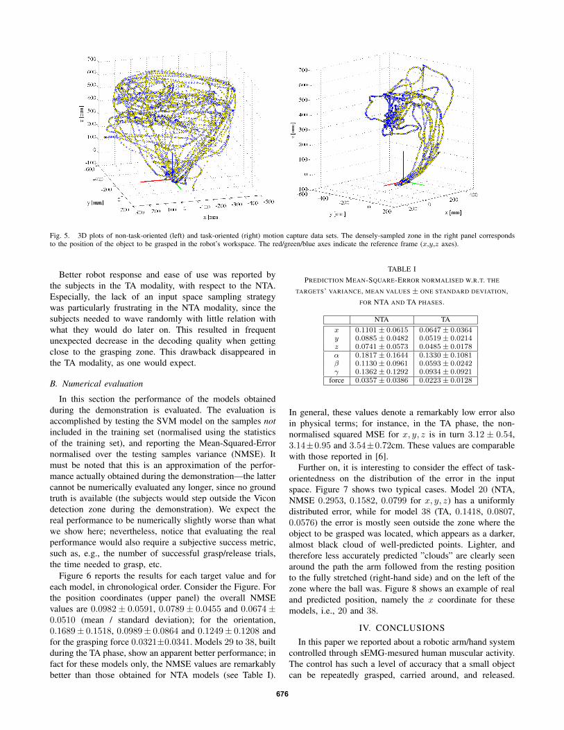
Fig. 5. 3D plots of non-task-oriented (left) and task-oriented (right) motion capture data sets. The densely-sampled zone in the right panel correspondsto the position of the object to be grasped in the robot’s workspace. The red/green/blue axes indicate the reference frame (x,y,z axes).
Better robot response and ease of use was reported bythe subjects in the TA modality, with respect to the NTA.Especially, the lack of an input space sampling strategywas particularly frustrating in the NTA modality, since thesubjects needed to wave randomly with little relation withwhat they would do later on. This resulted in frequentunexpected decrease in the decoding quality when gettingclose to the grasping zone. This drawback disappeared inthe TA modality, as one would expect.
B. Numerical evaluation
In this section the performance of the models obtainedduring the demonstration is evaluated. The evaluation isaccomplished by testing the SVM model on the samples notincluded in the training set (normalised using the statisticsof the training set), and reporting the Mean-Squared-Errornormalised over the testing samples variance (NMSE). Itmust be noted that this is an approximation of the perfor-mance actually obtained during the demonstration—the lattercannot be numerically evaluated any longer, since no groundtruth is available (the subjects would step outside the Vicondetection zone during the demonstration). We expect thereal performance to be numerically slightly worse than whatwe show here; nevertheless, notice that evaluating the realperformance would also require a subjective success metric,such as, e.g., the number of successful grasp/release trials,the time needed to grasp, etc.
Figure 6 reports the results for each target value and foreach model, in chronological order. Consider the Figure. Forthe position coordinates (upper panel) the overall NMSEvalues are 0.0982± 0.0591, 0.0789± 0.0455 and 0.0674±0.0510 (mean / standard deviation); for the orientation,0.1689± 0.1518, 0.0989± 0.0864 and 0.1249± 0.1208 andfor the grasping force 0.0321±0.0341. Models 29 to 38, builtduring the TA phase, show an apparent better performance; infact for these models only, the NMSE values are remarkablybetter than those obtained for NTA models (see Table I).
TABLE IPREDICTION MEAN-SQUARE-ERROR NORMALISED W.R.T. THE
TARGETS’ VARIANCE, MEAN VALUES ± ONE STANDARD DEVIATION,FOR NTA AND TA PHASES.
NTA TAx 0.1101± 0.0615 0.0647± 0.0364y 0.0885± 0.0482 0.0519± 0.0214z 0.0741± 0.0573 0.0485± 0.0178α 0.1817± 0.1644 0.1330± 0.1081β 0.1130± 0.0961 0.0593± 0.0242γ 0.1362± 0.1292 0.0934± 0.0921
force 0.0357± 0.0386 0.0223± 0.0128
In general, these values denote a remarkably low error alsoin physical terms; for instance, in the TA phase, the non-normalised squared MSE for x, y, z is in turn 3.12 ± 0.54,3.14±0.95 and 3.54±0.72cm. These values are comparablewith those reported in [6].
Further on, it is interesting to consider the effect of task-orientedness on the distribution of the error in the inputspace. Figure 7 shows two typical cases. Model 20 (NTA,NMSE 0.2953, 0.1582, 0.0799 for x, y, z) has a uniformlydistributed error, while for model 38 (TA, 0.1418, 0.0807,0.0576) the error is mostly seen outside the zone where theobject to be grasped was located, which appears as a darker,almost black cloud of well-predicted points. Lighter, andtherefore less accurately predicted ”clouds” are clearly seenaround the path the arm followed from the resting positionto the fully stretched (right-hand side) and on the left of thezone where the ball was. Figure 8 shows an example of realand predicted position, namely the x coordinate for thesemodels, i.e., 20 and 38.
IV. CONCLUSIONS
In this paper we reported about a robotic arm/hand systemcontrolled through sEMG-mesured human muscular activity.The control has such a level of accuracy that a small objectcan be repeatedly grasped, carried around, and released.
676

Fig. 6. Prediction Mean-Square-Error normalised w.r.t. the targets’ variance, for each dataset and target dimension. Models from 1 to 28 have beenobtained in the NTA modality, 29 to 38 with the TA modality.
Fig. 7. 3D plots of non-task-oriented (left) and task-oriented (right) squared Root-Mean-Error, model 20 (NTA, left) and 38 (TA, right). Larger and lightermarkers denote higher error.
Fig. 8. Real and predicted x coordinates for models 20 (upper panel) and 38 (lower panel).
677
The system was practically demonstrated during a robotictrade fair in 2010. Muscle activity is gathered using ninesurface electromyography electrodes. No precise placementof the electrodes is required, and no model of the hu-man arm/hand is employed, making the system essentiallysubject-independent — in fact, three subjects demonstratedthe system without noticeable performance differences. Afourth subject did a simpler demonstration without anyprevious knowledge about the system.
A standard machine learning method (namely, a SupportVector Machine) is used to build a point-to-point map be-tween muscle activity and hand position/orientation/graspingforce. The map relies on gravity compensation and rather lowmovement speed, which enforces a many-to-one relationshipbetween sEMG signals and position. Numerical (offline)evaluation indicates in a few centimeters the precision thatcan be obtained by the system; orientation and force guessinghave similar, although slightly worse, precisions.
It was noted that the performance of the system is consid-erably higher when a task-oriented training modality is used.This is due to finer sampling of the input space in the zone ofinterest (namely, where the grasping mostly happens) whichleads to smaller error rates where it is required.
In [7] a detailed report is given about how to avoid thewell-known time variance of the sEMG signal, in particularas far as muscle fatigue is concerned — a problem that wedid not notice. The reasons of this improvement could liein the choice of the sEMG features, in the reliability of theelectrodes or even in the reciprocal adaptation of the humansubjects to the system. In fact, all subjects reported a feelingof ”learning to control the arm” as the testing phase wouldproceed. Task-orientedness seems to be essential from thispoint of view, too.
The DLR Light-weight Robot III we used in this paper isoperated in impedance control, which is essential in applica-tions in which the environment is unknown. Furthermore thehuman-friendly control architecture used in combination withthe robot enables the operator to be within the workspaceof the robot and interact with it. This feature makes thesystem suitable for a variety of applications in which physicalinteraction between humans and robots occurs.
Future work
Further investigation into the sEMG signal is envisioned,in particular as the end-effector reaches the grasping zone.In that case the muscular system is expected to stiffen up.This could be used to estimate 3D stiffness using sEMG,a problem which is still largely open and whose solutionwould have applications in a number of fields of robotic(e.g., remote surgery or high-accuracy teleoperation).
The assumption of slow movement can probably be loos-ened if a more sophisticated form of robotic control isenforced, namely, considering estimating the end-effectorvelocity as well as the position, and then using a hybridposition/velocity robot controller. This is also subject tofurther research.
Lastly, the system as described and demonstrated in thispaper is probably not directly optimally usable for genericteleoperation—indeed, more accurate ways of estimating theend-effector position rather than sEMG can be found; how-ever this setup might be of great use when magnetic trackingcannot be used for training. An even more interesting futureapplication is rehabilitation of muscular-disorder patients, inwhich a weak or distorted sEMG signal could be used totrain the system and let the patient see the arm move asdesired. Such procedures are well known to dramaticallyshorten rehabilitation effort.
REFERENCES
[1] S. Ferguson and G. Reg Dunlop. Grasp recognition from myoelectricsignals. In Proceedings of the Australasian Conference on Roboticsand Automation, Auckland, New Zealand, pages 83—87, 2002.
[2] A.D.C. Chan and K.B. Englehart. Continuous myoelectric controlfor powered prostheses using hidden markov models. BiomedicalEngineering, IEEE Transactions on, 52(1):121–124, Jan. 2005.
[3] P. A. Parker, K. Englehart, and B. Hudgins. Myoelectric signalprocessing for control of powered limb prostheses. Journal ofelectromyography and kinesiology, 16(6):541—548, 2006.
[4] S. Bitzer and P. van der Smagt. Learning EMG control of arobotic hand: towards active prostheses. In Proc. IEEE InternationalConference on Robotics and Automation, pages 2819–2823, 2006.
[5] C. Castellini and P. van der Smagt. Surface EMG in advanced handprosthetics. Biological Cybernetics, 100(1):35—47, 2008.
[6] P. K. Artemiadis and K. J. Kyriakopoulos. EMG-based control of arobot arm using low-dimensional embeddings. IEEE Transactions onRobotics, 26(2):393—398, 2009.
[7] P. K. Artemiadis and K. J. Kyriakopoulos. An emg-based robotcontrol scheme robust to time-varying EMG signal features. IEEETransactions on Information Technology in Biomedicine, 14(3):582—588, 2010.
[8] P. K. Artemiadis and K. J. Kyriakopoulos. A switching regime modelfor the emg-based control of a robot arm. IEEE TRANSACTIONSON SYSTEMS, MAN, AND CYBERNETICSPART B: CYBERNETICS,41(1):53—63, 2011.
[9] C. Castellini, E. Gruppioni, A. Davalli, and G. Sandini. Fine detectionof grasp force and posture by amputees via surface electromyography.Journal of Physiology (Paris), 103(3—5):255—262, 2009.
[10] B. E. Boser, I. M. Guyon, and V. N. Vapnik. A training algorithmfor optimal margin classifiers. In D. Haussler, editor, Proceedings ofthe 5th Annual ACM Workshop on Computational Learning Theory,pages 144–152. ACM press, 1992.
[11] A. Albu-Schaffer, S. Haddadin, C. Ott, A. Stemmer, T. Wimbock, andG. Hirzinger. The DLR lightweight robot: design and control conceptsfor robots in human environments. Industrial Robot: An InternationalJournal, 34(5):376–385, 2007.
[12] A. Albu-Schaffer, C. Ott, and G. Hirzinger. A unified passivity-based control framework for position, torque and impedance control offlexible joint robots. The International Journal of Robotics Research,26(1):23, 2007.
[13] S. Haddadin, A. Albu-Schaffer, A. De Luca, and G. Hirzinger.Collision Detection and Reaction: A Contribution to Safe PhysicalHuman-Robot Interaction. IEEE/RSJ Int. Conf. on Intelligent Robotsand Systems (IROS2008), Nice(France), 2008.
[14] S. Haddadin, M. Suppa, S. Fuchs, T. Bodenmuller, A. Albu-Schaffer,and G. Hirzinger. Towards the Robotic Co-Worker. In submitted to: In-ternational Symposium on Robotics Research (ISRR2007), Lausanne,Switzerland, 2009.
[15] S. Haddadin, A. Albu-Schaffer, and G. Hirzinger. Requirements forSafe Robots: Measurements, Analysis and New Insights. InternationalJournal on Robotics Research, 28(11-12):1507–1520, 2009.
[16] S. Haddadin, Parusel S., Vogel J., R. Belder, Rokahr T., A. Albu-Schaffer, and G. Hirzinger. Holistic design and analysis for thehuman-friendly robotic co-worker. accepted at: IEEE/RSJ Int. Conf.on Intelligent Robots and Systems (IROS2010), Taipeh(Taiwan):Invitedpaper, 2010.
[17] Bauml B. and G. Hirzinger. When hard realtime matters: Softwarefor complex mechatronic systems Robotics and Autonomous Systems.Robotics and Autonomous Systems, 56, 2008.
678