Embed Size (px)
Citation preview
Aerosol Science 37 (2006) 306–322www.elsevier.com/locate/jaerosci
Stabilization of monodisperse electrosprays in the multi-jet modevia electric field enhancement
Marie-Hélène Duby, Weiwei Deng, Kyoungtae Kim, Tommaso Gomez,Alessandro Gomez∗
Department of Mechanical Engineering, Yale University, New Haven, CT 06520-8286, USA
Received 6 October 2004; received in revised form 4 May 2005; accepted 30 May 2005
This paper was dedicated to the 70th birthday of Professor Daniel Rosner.
Abstract
The electrospray of conducting liquids operated in the cone-jet mode is well known to have the unique ability ofgenerating droplets uniform in size over a phenomenal range of sizes depending primarily on the liquid flow rateand physical properties. Since there is a monotonic dependence of size on flow rate, the liquid flow rates that canbe dispersed are modest if the goal is to produce very small (below a few micrometers in diameter) droplets. Yet,this is precisely the application niche for which few, if any, atomization alternatives are available. Multiplexing thespray source is indispensable for the electrospray capabilities to have an impact in high-value-added applications.We report here on a novel approach to multiplexing based on a well-known, but hitherto unexploited, regime ofoperation, the multi-jet mode. Ordinarily, such a mode is rather unsteady and the range of flow rates at whichappreciable multiplexing is achieved is small. However, if the multi-jet mode is anchored by some sharp features(e.g., grooves, ridges, etc.) machined at the outlet of the atomizer, to intensify the electric field at discrete pointsaround its perimeter, then the cone-jets are simultaneously anchored at these features and a stable mode of operationis identified over several hundreds of volts and a broad range of flow rates. Most importantly, so long as themachining is accurately reproduced from point to point, droplets generated do not vary significantly in size fromspray to spray. As a result, a compact, inexpensive and versatile multiplexing system is realized without sacrificingdroplet monodispersity.� 2005 Elsevier Ltd. All rights reserved.
Keywords: Electrospray; Multiplexing; Multi-jet; Monodisperse; Droplets
∗ Corresponding author. Tel.: +1 203 432 4384; fax: +1 203 432 7654.E-mail address: [email protected] (A. Gomez).
0021-8502/$ - see front matter � 2005 Elsevier Ltd. All rights reserved.doi:10.1016/j.jaerosci.2005.05.013

M.-H. Duby et al. / Aerosol Science 37 (2006) 306–322 307
1. Introduction
Electrostatic means for liquid dispersion in minute droplets are used in a variety of technological appli-cations (Bailey, 1988). The class of atomizers in which the dispersion of the liquid is driven exclusivelyby electric forces is referred to heretofore as electrospray (ES). Within this class we will further restrictour attention to a particular type characterized by the additional feature of a tight control of the sizedistribution of the resulting aerosol. Such a system can be implemented by feeding a liquid with sufficientelectric conductivity through a small opening, such as the tip of a capillary tube or a suitably treated“hole”, maintained at several kilovolts relative to a ground electrode positioned a few centimeters away.The liquid meniscus at the outlet of the capillary takes a conical shape under the action of the electricfield, with a thin jet emerging from the cone tip. This jet breaks up farther downstream into a spray offine, charged droplets. In view of the morphology of the liquid meniscus, this regime is labeled as thecone-jet mode (Cloupeau & Prunet-Foch, 1989).
Among the key features distinguishing the cone-jet electrospray from other atomization techniquesare quasi-monodispersity of the droplets; Coulombic repulsion of the charged droplets, which inducesspray self-dispersion, prevents droplet coalescence and enhances mixing with the oxidizer; and the useof a spray “nozzle” with a relatively large bore with respect to the size of the generated droplets, whichimplies that liquid line obstruction risks are minimized. The cone-jet mode can produce droplets/particlesover a wide size range, from submicrometer to hundreds of micrometers, depending on liquid flow rate,applied voltage and liquid electric conductivity. Especially in the submicrometer range, the capability ofproducing monodisperse particles with relative ease is unique among other aerosol generation schemes.The reader is referred to previous special issues in this journal for a series of articles on this technology(Volume 25 (6), 1994; Volume 30 (7), 1999).
Electrospray ionization mass spectrometry (ESI-MS), spearheaded by the pioneering work of JohnB. Fenn at Yale in the 1980s (Fenn, Mann, Meng, Wong, & Whitehouse, 1989), leading to his 2002Chemistry Nobel Prize, is the only practical application of the electrospray in widespread use. Keydrawbacks that have hampered applications to other areas are the low flow rates at which the cone-jet mode can be established and the restrictions on the liquid physical properties of the liquids thatcan be dispersed with this technique. The difficulty is particularly severe in applications requiring thatthe initial droplet size be small, as for example in drug inhalation or nanoparticle synthesis. Since theelectrospray exhibits a monotonic dependence of droplet size on flow rate (e.g., Chen, Pui, & Kaufman,1995; Ganan-Calvo, Davila, & Barrero, 1997; Tang & Gomez, 1996), if one needs small droplets togenerate nanoparticles, production rate may be minuscule (Gomez, Bingham, de Juan, & Tang, 1997).The smaller the desired particle size, the smaller the production rate. To provide quantities suitable forbiological tests, pharmaceutical treatment or other high-value-added applications, multiplexing the spraysource, is indispensable.
Multiplexing by “brute force” duplication of several capillaries operating in parallel has been inves-tigated to a limited degree (e.g., Kyritsis, Guerrero-Arias, Roychoudhury, & Gomez, 2002; Rulison &Flagan, 1993). It may be cumbersome and impractical by more than one order of magnitude. Furthermore,compacting the sources over a small atomizer “footprint” may prove challenging. The delivery of liquidflow from a single source through a distributor with serrations was reported by Almekinders and Jones(1999), but resulted in clearly polydisperse droplet size distributions. The multiplexing goal may be-come easier to tackle with recent progress in the field of MEMS (micro-electro mechanical systems)(Deng, Klemic, Li, Reed, & Gomez, 2005), namely, by adapting conventional silicon integrated circuit

308 M.-H. Duby et al. / Aerosol Science 37 (2006) 306–322
fabrication technology (micromachining) to the manufacturing of electrospray sources, multiplexing de-vices at unparalleled scales and with micrometer precision may become feasible. Even if such an approachwere to materialize, cost may remain prohibitive until the advent of mass production.
We report here on a particular approach to multiplexing based on a well-known, but hitherto seldomexploited, regime of operation of the electrospray, the multi-jet mode (Cloupeau & Prunet-Foch, 1990;Zeleny, 1915). At sufficiently high voltages a liquid that can be operated in the conventional cone-jetmode may disperse into a multitude of cone-jets emanating from a single bore and typically spreadingout at an angle with respect to the axis of the nozzle through which the liquid is pumped. We will describeconditions under which stable operation in this mode may lead to a compact, inexpensive multiplexingsystem, without sacrificing the crucial feature of monodispersity of the generated droplets.
2. Experimental system
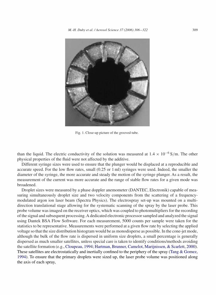
The experimental system consisted of a syringe pump to feed and meter precise liquid flow rates througha metal tube acting as the electrospray source. A Teflon tube connected the syringe needle to the metaltube at the outlet of which the electrospray was anchored. For the reference experiments in the singlecone-jet mode, two tubes were used: a larger one (1.6 mm O.D., 1.2 mm I.D.) and a capillary (1.6 mmO.D., 0.11 mm I.D.). For the multi-jet mode of operation, two large tubes were used with approximatelythe same dimensions (3.2 mm O.D., 1.8 mm I.D.). One of them was in brass and had its outlet machinedflat and polished. The other in stainless steel was machined at one end with 12 grooves using wireelectrodischarge machining (EDM) to ensure good reproducibility of the geometric features of eachgroove (Fig. 1). The metal tube was charged at an electrical potential of several kilovolts. At a distanceof a few centimeters from the tip of the metal tube was located the flat ground electrode, consisting of ametal ring covered with a metal mesh to prevent liquid accumulation on the electrode.
The current was measured by connecting the virtual ground plate to a voltmeter of known inputimpedance. Visual observation of the mode of operation was made through a telescope focused on theliquid meniscus. To count the jets accurately, a He–Ne laser beam was focused into a sheet by twolenses and shone perpendicularly to the axis of the metal tube, a few millimeters downstream of thecone-jets. Scattering of the charged droplets in each spray resulted in the visualization of individual spraycross-sections appearing as small discs.
Heptane was electrosprayed with an electrical conductivity enhancer, Stadis 450 (Du Pont), at a con-centration of 0.3% by weight, similarly to our earlier studies (Tang & Gomez, 1996). The selection of aliquids fuel for the testing was motivated by the need to apply the technique to the dispersion of liquidfuels in the development of a mesoscale combustor (Kyristis, Coriton, Faure, Roychoudhury, & Gomez,2004). This fuel had been extensively used in our laboratory in fundamental studies on the combustion ofelectrosprays (e.g., Chen & Gomez, 1997). Before loading the liquid in the syringe, it was sonicated fora few minutes and care was taken in the loading procedure to minimize the formation of microbubbles.
The liquid conductivity was measured by feeding the liquid through a small Teflon tube with a metalcapillary at each outlet, as originally suggested by J.B. Fenn and documented by Tang (1994). By applyingdifferent potentials across the capillaries and measuring the current in the circuit, the resistance of theliquid could be inferred. From R = l/(k × A), where k is the electrical conductivity, A the cross-sectionand l the length of the Teflon tube, one can calculate the conductivity. The underlying assumption is thatthe circuit consists of two resistances in parallel, with the Teflon resistance orders of magnitudes larger
M.-H. Duby et al. / Aerosol Science 37 (2006) 306–322 309
Fig. 1. Close-up picture of the grooved tube.
than the liquid. The electric conductivity of the solution was measured at 1.4 × 10⁻⁶ S/m. The otherphysical properties of the fluid were not affected by the additive.
Different syringe sizes were used to ensure that the plunger would be displaced at a reproducible andaccurate speed. For the low flow rates, small (0.25 or 1 ml) syringes were used. Indeed, the smaller thediameter of the syringe, the more accurate and steady the motion of the syringe plunger. As a result, themeasurement of the current was more accurate and the range of stable flow rates for a given mode wasbroadened.
Droplet sizes were measured by a phase doppler anemometer (DANTEC, Electronik) capable of mea-suring simultaneously droplet size and two velocity components from the scattering of a frequency-modulated argon ion laser beam (Spectra Physics). The electrospray set-up was mounted on a multi-direction translational stage allowing for the systematic scanning of the spray by the laser probe. Thisprobe volume was imaged on the receiver optics, which was coupled to photomultipliers for the recordingof the signal and subsequent processing.A dedicated electronic processor sampled and analyzed the signalusing Dantek BSA Flow Software. For each measurement, 5000 counts per sample were taken for thestatistics to be representative. Measurements were performed at a given flow rate by selecting the appliedvoltage so that the size distribution histogram would be as monodisperse as possible. In the cone-jet mode,although the bulk of the flow rate is dispersed in uniform size droplets, a small percentage is generallydispersed as much smaller satellites, unless special care is taken to identify conditions/methods avoidingthe satellite formation (e.g., Cloupeau, 1994; Hartman, Brunner, Camelot, Marijnissen, & Scarlett, 2000).These satellites are electrostatically and inertially confined to the periphery of the spray (Tang & Gomez,1994). To ensure that the primary droplets were sized up, the laser probe volume was positioned alongthe axis of each spray,

310 M.-H. Duby et al. / Aerosol Science 37 (2006) 306–322
4 6 8 10 12 140
50
100
150
200
250
300
350
400
MULTI-JETCONE-JETCur
rent
(nA
)
Voltage (kV)
Fig. 2. Current vs. voltage for the smooth tube (Q̇ = 30 ml/h).
3. Results and discussion
3.1. Multiplexing from a single smooth tube
Fig. 2 shows a typical current versus voltage graph, obtained by electrospraying heptane in the multi-jet mode using the large brass metal tube with a polished end. The purpose of this figure is primarily tocontrast the well-known behavior in the multi-jet mode to what will be found when the tip of the atomizeris suitably modified (see Fig. 4). In the lower voltage range 6.5–8.0 KV, a single cone-jet appeared, withblurred contour suggesting an inherently unstable mode of operation. As the voltage was raised in themulti-jet range of operation, few jets appeared and could be anchored stably at positions equidistancedfrom each other. If the voltage was raised further, more cone-jets appeared. At the peak current, at about12.5 KV, on the order of 20 cone-jets were present at the edge of the tube. The jets were not very stable.Examination of the droplets generated by phase doppler anemometry enabled us to measure the size ineach jet. Much to our surprise, the average size from spray to spray was quite uniform, as shown in Fig. 3in which the variability of the average droplet size in each spray is plotted versus the azimuthal coordinate,ϑ. Within each spray the size distribution was quasi-monodisperse, with typical size spread, defined as(D0.9 − D0.1)/D0.5, less than 0.1. In the above relationship, Di represents the value for which i-fractionof the liquid volume is in droplets of smaller diameters. This result suggests that the multi-jet mode con-sists of an array of monodisperse cone-jet electrosprays. The apparent instability of the regime is merelythe result of some positional jitter of the individual cone-jets, rather than more serious instabilities thatwould affect the size distribution of the generated droplets. The uniformity in size would suggest that thetotal flow rate is equipartitioned evenly among the coexisting cone-jets, if, as in the present case, effortsare made to ensure symmetry in the geometry of the electrodes and the liquid injection. Repeating thesame current/voltage experiment at 20 ml/h yielded similar results. At low flow rates, i.e. 6 ml/h, however,results were quite different. The cone-jet was never effectively stabilized, even with fewer jets. Noticealso that the average flow rate per jet would still be well above the minimum flow rate that can be electro-sprayed in an individual cone-jet for such a mixture (Tang & Gomez, 1996), although direct comparisonswith our earlier work are difficult to make since this variable depends on the electrode configuration.

M.-H. Duby et al. / Aerosol Science 37 (2006) 306–322 311
0 50 100 150 200 250 300
0
2
4
6
8
10
12
14
16
18
20
Dro
plet
Siz
e (µ
m)
θ (degree)
Fig. 3. Average droplet diameter in individual cone-jet electrosprays anchored in the multi-jet mode to the smooth atomizer(Q̇ = 30 ml/h; on the order of 25 jets).
The picture that emerges from these results is that the multi-jet mode is surprisingly effective atgenerating monodisperse droplets without the need of special manufacturing approaches. Yet, the rangeof flow rates over which this regime applies with an appreciable level of multiplexing of at least oneorder of magnitude is narrow and, even within this range, the number of jets is very sensitive to theapplied voltage. This result, if generally applicable to liquids of different physical properties, poses twoproblems from an application viewpoint: first, the disappointing behavior at low flow rates suggest thatthe approach would fail precisely in the potentially most interesting regime in which the smallest dropletswould be generated, which would be the one of interest in some of the high-value added applications;second, the variability of the number of jets with voltage and their positional instabilities suggest thatin a “production mode” the electrospray would have to be constantly monitored and the applied voltagefrequently tweaked to the design operation.
3.2. Grooved mode of operation
The observation that the cone-jet instability was positional, in the sense that conditions seem ratherstable and promising from a monodispersity perspective, prompted us to attempt to anchor the multi-jetregime by designing identical geometric features at the atomizer outlet in a symmetric pattern, for thepurpose of stabilizing the cone-jets at particular locations around the opening circumference. To that end,a number of grooves were machines on the tube face by wire electric discharge machining, as shownin Fig. 1. The grooves would anchor the multiple jets, once a sufficiently high voltage was applied withrespect to a ground electrode, by virtue of the small radius of curvature and more intense electric fieldpresent at these locations. In that respect the shape of the indentation in the surface should not be critical.
Solutions of Laplace equation for the electric potential between the two electrodes were carried outwith different spatial resolution using FEMlab (COMSOL Inc., 2005) for a simplified nozzle geometrywith only four grooves. The field, computed at the outermost radial location, revealed the presence ofspikes, corresponding the location of the grooves, where the field intensity was at least a factor of twolarger than the background value along the rest of the circumference. Since no account was taken of

312 M.-H. Duby et al. / Aerosol Science 37 (2006) 306–322
6
4 6 8 10 12 14
10 11 12 130
20
40
60
80
100
120
140
160
11 jets
10 jets
6 jets
8 jets
4 jets
3 jets
2 jets
Cur
rent
(nA
)
Voltage (kV)
Voltage (kV)
0
50
100
150
200
250
300
350
10 jets
Unstable sub-grooved modeCur
rent
(nA
)
987
(a)
(b)
Fig. 4. Current vs. voltage for the grooved tube operated at Q̇ = 6 ml/h (a) and Q̇ = 30 ml/h (b).
the presence of the liquid that was wetting the surface nor of the charged droplets and attending spacecharge, the results are to be considered qualitative. Nevertheless, they are revealing since they show aperiodic electric field along the circumference of the nozzle, with peaks in correspondence of the groovesthat are dramatically larger than the background field at the nozzle, as intuitively anticipated from firstprinciples. As shown below, under certain conditions, these spikes in field strength at the grooves may besufficient to lock otherwise unstable cone-jets in place. Furthermore, the multi-jet regime can be reachedat an operating voltage lower than in the case of smooth nozzles, thereby minimizing the risk of electricdischarge.
Fig. 4 shows typical current versus voltage graphs, obtained for the same liquid at two flow rates, 6 ml/h(Fig. 4a) and 30 ml/h (Fig. 4b). Fig. 5 shows several pictures that were obtained under different conditions,as elaborated below. In Fig. 4a, one can notice the more or less monotonic increase of the current in astep-ladder pattern, as the spray transitioned from a well-pronounced initial plateau, corresponding tothe single cone-jet (Fig. 5a), to a multi-jet regime with anywhere from 2 to 11 jets. Figs. 5b and c showthe morphology in some of the initial phase of this transition, with the appearance of three and fourequidistanced jets along the tube circumference. This regime in which the number of jets is smaller than

M.-H. Duby et al. / Aerosol Science 37 (2006) 306–322 313
Fig. 5. Pictures of various modes of operation, with close-up views of the voltage effect in the grooved mode.
the number of grooves in the atomizer tip is labeled sub-grooved mode. Next, as the voltage was furtherraised, a new plateau was reached, spanning several hundred volts, within which the grooved regimewas established, with as many jets as there were grooves (Fig. 5d). The current was nearly constant inthis mode and, as the voltage was raised, each cone-jet shrunk. The cone-jet appearance is documentedin the sequence of Figs. 5e–g and is consistent with observations made in the single cone-jet mode,reporting shrinkage of the cone as the voltage rises (Hayati, Bailey, & Tadros, 1987). The anchoring of

314 M.-H. Duby et al. / Aerosol Science 37 (2006) 306–322
the cone-jet may occur either at the top of the groove or directly inside the groove. Beyond 9 KV, thecurrent surprisingly dipped in correspondence of a collapse of the grooved mode: some jets were, in fact,disappearing and leaving their groove empty, while others appeared in grooves that had already beenoccupied. As the current began to rise again, more and more jets formed and several but not all of thegrooves anchored two jets. Fig. 5h shows one such an example. Finally, at the highest voltage, a hissingsound became audible, which was a prelude to corona discharge and unstable spray disruption. Beyondthis limit, the cone-jets were not stable but appeared to vibrate in the grooves.
Similar graphs were obtained at higher flow rates, as in Fig. 4b corresponding to 30 ml/h. The trendsare similar to the lower flow rate case with some noteworthy differences:
(a) In the transition from single cone-jet to grooved mode, the current increase showed less of thestaircase pattern that had been observed at 6 ml/h and becomes strictly monotonic.
(b) In this transition, it was difficult to establish a subgrooved regime with few jets.(c) The current in the grooved mode increased, rather than being constant as the flow rate increased.(d) The dip in current, past the grooved regime, became less and less noticeable as the flow rate increased
and the flow rate transitioned to a condition in which the flow rate effluxing through a single groovewas split into two stable jets, resulting in a total of 24 jets. While this regime is potentially the mostdesirable in terms of multiplexing, it did not appear to be as stable as the grooved mode, althoughits stability improved as the flow rate increased.
(e) Eventually, also at larger flow rates, the hissing regime was reached.
A comparison of the system behavior of the grooved mode versus the results obtained in Fig. 2 for a smoothnozzle suggests that the stability of the system improved significantly, which allowed us to explore fea-tures of this electric field-anchored multi-jet mode in greater detail, as elaborated in the remainder of thearticle.
3.3. Current and stability domain
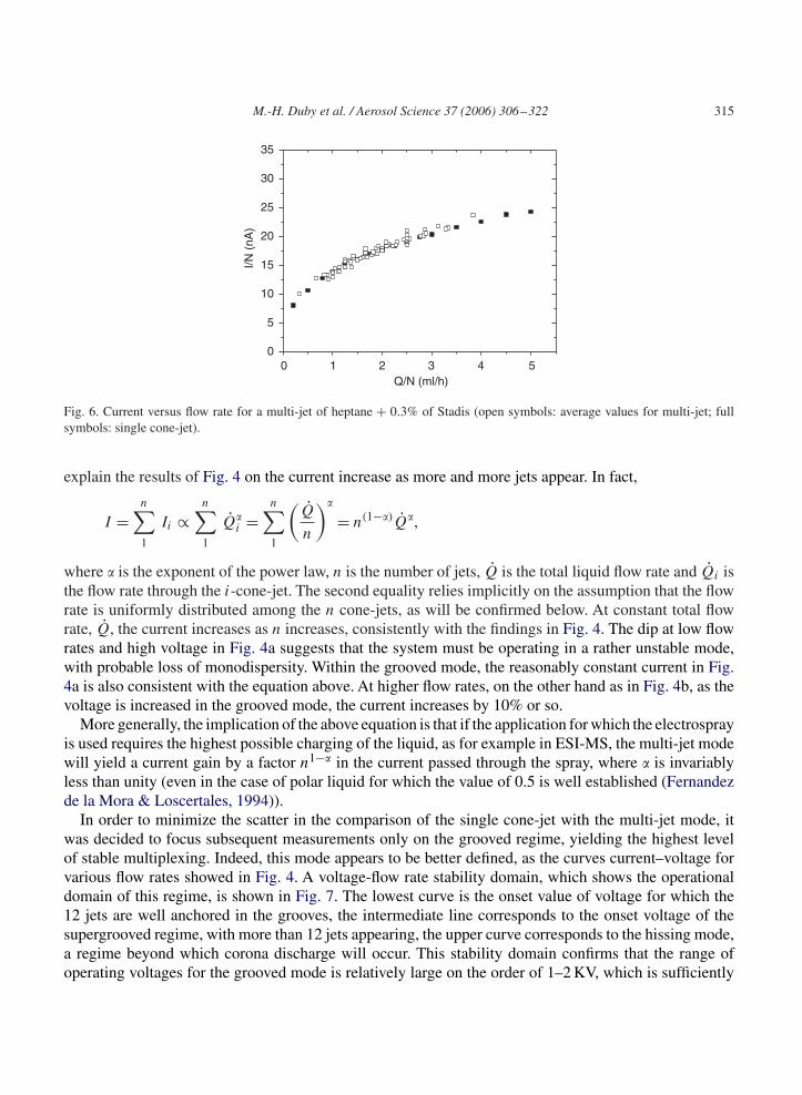
To relate the behavior of the multi-jet regime to the better known single cone-jet mode, the averagecurrent per jet was compared to that measured in a separate experiment with the smaller tubes operatedin the single cone-jet regime. In other words, with the electrospray in either the sub-grooved mode orgrooved mode, that is, with up to 12 jets, the total current was measured and the number of jets werecounted, with the ratio of the values yielding the average current per jet. Results are plotted in Fig. 6.It appears that the average current per jet obeys, within the experimental scatter, the same power law asin the single cone-jet mode. As a result, the current power law for the multi-jet must be close to that ofthe single jet. Although, considerable work has been made in deriving scaling laws for different liquidsthat are largely based on dimensional analysis (Fernandez de la Mora & Loscertales, 1994; Ganan-Calvoet al., 1997), in the present case we will refrain from applying such laws since they are not well establishedfor the low conductivity liquid used in these experiments and no comparisons with other fluids will bemade in this study. Thus, it suffices to compare the relative behavior of the multi-jet mode versus thesingle cone-jet counterpart. Part of the scatter may be due to small variations in current that depends onthe number of jets, with the grooved mode resulting in the largest current per jet. The average current perjet scales with the average flow rate per jet as I/n ∼ (Q/n)0.36, which is essentially the same, within theexperimental scatter, as I ∼ Q0.35 obtained for the single cone-jet mode. This finding can also help us
M.-H. Duby et al. / Aerosol Science 37 (2006) 306–322 315
0 50
5
10
15
20
25
30
35
I/N (
nA)
Q/N (ml/h)4321
Fig. 6. Current versus flow rate for a multi-jet of heptane + 0.3% of Stadis (open symbols: average values for multi-jet; fullsymbols: single cone-jet).
explain the results of Fig. 4 on the current increase as more and more jets appear. In fact,
I =n∑1
Ii ∝n∑1
Q̇�i =
n∑1
(Q̇
n
)�
= n(1−�)Q̇�,
where � is the exponent of the power law, n is the number of jets, Q̇ is the total liquid flow rate and Q̇i isthe flow rate through the i-cone-jet. The second equality relies implicitly on the assumption that the flowrate is uniformly distributed among the n cone-jets, as will be confirmed below. At constant total flowrate, Q̇, the current increases as n increases, consistently with the findings in Fig. 4. The dip at low flowrates and high voltage in Fig. 4a suggests that the system must be operating in a rather unstable mode,with probable loss of monodispersity. Within the grooved mode, the reasonably constant current in Fig.4a is also consistent with the equation above. At higher flow rates, on the other hand as in Fig. 4b, as thevoltage is increased in the grooved mode, the current increases by 10% or so.
More generally, the implication of the above equation is that if the application for which the electrosprayis used requires the highest possible charging of the liquid, as for example in ESI-MS, the multi-jet modewill yield a current gain by a factor n1−� in the current passed through the spray, where � is invariablyless than unity (even in the case of polar liquid for which the value of 0.5 is well established (Fernandezde la Mora & Loscertales, 1994)).
In order to minimize the scatter in the comparison of the single cone-jet with the multi-jet mode, itwas decided to focus subsequent measurements only on the grooved regime, yielding the highest levelof stable multiplexing. Indeed, this mode appears to be better defined, as the curves current–voltage forvarious flow rates showed in Fig. 4. A voltage-flow rate stability domain, which shows the operationaldomain of this regime, is shown in Fig. 7. The lowest curve is the onset value of voltage for which the12 jets are well anchored in the grooves, the intermediate line corresponds to the onset voltage of thesupergrooved regime, with more than 12 jets appearing, the upper curve corresponds to the hissing mode,a regime beyond which corona discharge will occur. This stability domain confirms that the range ofoperating voltages for the grooved mode is relatively large on the order of 1–2 KV, which is sufficiently

316 M.-H. Duby et al. / Aerosol Science 37 (2006) 306–322
0 10 15 20 25 30 35 40 450
2
4
6
8
10
12
14
16
Vol
tage
(kV
)
Flow Rate (ml/h)5
Fig. 7. Stability domain in the voltage/flow-rate plane for the grooved multi-jet mode (full squares: voltage onset; open squares:upper voltage of grooved mode; full triangles: hissing mode).
broad to ensure easy establishment of this regime in an experiment. Similar behavior was observed withother hydrocarbons such as JP-8 of interest in the development of mesoscale combustors (Kyritsis et al.,2004). This result should be contrasted with the far more unstable behavior of the system with a smoothnozzle, as discussed in connection with Fig. 2.
3.4. Droplet size measurements
The comparison of current power laws in the single cone-jet mode and multi-jet modes suggests thateach cone-jet in the multi-jet regime behaves in the same way as an isolated cone-jet. Confirmationof this observation is now sought with respect to the monodispersity of the generated droplets andtheir uniformity from jet to jet. Since the grooves are symmetrically and uniformly disposed, exceptfor machining imperfection or asymmetries in the liquid pumping system, there is no reason to expectthat the flow rate be not equipartitioned among the multiple cone-jets, which should lead to uniformitythroughout the spray cloud. Confirmation of this supposition with respect to the uniformity of the jets,and hence that of the flow rate, can be offered by the measurements of the size of the droplet emergingfrom the jet, thanks to the monotonic relation between the flow rate and the droplet size as shown forthe single cone-jet (Tang & Gomez, 1996). Fig. 8 presents the average droplet size for three flow rates,6 ml/h, 12 ml/h and 18 m/l, respectively. To quantify the size scatter from jet to jet, a relative standarddeviation (RSD) is defined as
RSD = 1
D̄
√∑Ni=1(D̄i − D̄)2
n − 1,
where D̄i is the average droplet diameter for jet i, and D̄ = ∑D̄i/n is the droplet size averaged over all
jets. The uniformity of the droplet size is good, with the RSD < 10%, which is comparable to the degreeof non-uniformity in size within a single jet. The relative standard deviation was found to be significantly

M.-H. Duby et al. / Aerosol Science 37 (2006) 306–322 317
0 45 90 135 180 225 270 3150
5
10
15
20
25
30
35
Dro
plet
Siz
e (µ
m)
θ (degree)
Fig. 8. Average droplet diameter at different flow rates in individual cone-jet electrosprays anchored in the grooved mode to thegrooved atomizer (full squares: Q̇ = 6 ml/h; open squares: Q̇ = 12 ml/h; full triangles: Q̇ = 18 ml/h).
larger in the sub-grooved mode, which is another indirect confirmation that flow equipartition is improvedin the grooved mode.
The present approach to multiplexing has some similarity with the dispersion through a serrated openingby Almekinders and Jones (1999). No details are given in that article of the mechanism at work andwhether the serration was used for a electric field-based stabilization effect or as a means to distributingthe flow rate at the outlet. Furthermore, the reported size distributions are significantly polydisperse, whichimplies that our primary objective of preserving the uniformity of droplets size from jet to jet was notfulfilled in their study. We conclude that the similarity is not substantive and the approach described heremust be significantly different from theirs. Similarities may exist with approaches involving a variety ofelectrodes with peculiar geometries that are discussed in the patent literature but were never documentedquantitatively (e.g., Coffee, Noakes, Bancroft, & Bals, 1987; Colclough & Noakes, 1987; Escallon &Tyner, 1987).
In Fig. 9 the average droplet diameter in the grooved mode has been plotted versus the average flow rateQ̇/n and compared with data obtained in the single cone-jet mode for which n=1. The results for the multi-jet regime appear to be consistent with the size versus flow rate curve of the single jet. However, the scatterof the points plotted for the grooved mode is non-negligible, e.g. 15% at 18 ml/h. The discrepancy seemsto increase with the flow rate, which may be attributed to the fact that the range of voltage within whichthe grooved mode is operated becomes larger for large flow rates. As a consequence of the measurementtechnique, the droplet size might have been measured for a voltage somewhat higher than the onset value.For a given flow rate, the droplet size decreases when the voltage increases, particularly at large flow rate(Tang & Gomez, 1996).
3.5. Groove geometry, size uniformity and machining accuracy
We assessed the influence of geometric parameters on the electrospray behavior, including number ofgrooves, groove width and depth. The conclusion from these tests was that the first two parameters arethe most important. Depending on how wide is the groove either one or two cone-jets per groove can

318 M.-H. Duby et al. / Aerosol Science 37 (2006) 306–322
0.0 0.5 1.0 1.5 2.00
5
10
15
20
25
30
Dro
plet
Siz
e (µ
m)
Flow Rate (ml/h)
Fig. 9. Comparison of droplet size dependence on flow rate. Open squares: droplet diameter versus flow rate for single cone-jet.Full triangles: average droplet diameter versus average flow rate per cone-jet in the multi-jet regime.
be stabilized. Clearly, there is a tradeoff between widening the groove and fitting more of them on theannular surface at the outlet of a tube.
A detailed examination of the size variation from jet to jet in similarly grooved atomizers that had beenmachined with a small blade, less reproducibly than with wire EDM, showed some pattern of the averagesize with jet position which was repeated for almost all the measurements and seemed to correlate withfabrication defects. This observation raised the concern that non-uniformities may stem from machiningdefect at the edge of the grooves. Whether the uniformity can be further improved with more precisemachining remains to be seen. Certainly, conventional machining with spatial resolution better thanwire EDM is difficult to achieve. Probably, the only approach is via microfabrication. We can test thishypothesis by checking if a deliberately introduced defect significantly worsens the non-uniformity fromjet to jet. To that end, a grooved atomizer was damaged in two positions, as highlighted by the circledareas in Fig. 10.
Size measurements obtained with such a tube are shown in Fig. 11. The grooved mode was difficult toestablish. A 12-jet pattern was actually obtained in a super-grooved mode, with one empty groove andanother exhibiting a double jet. A 10-jet subgrooved mode looked more stable, with no time dependentbehavior of the jets. However, the non-uniformity in average size is dramatically worsened, as comparedto Fig. 8. For each flow rate, the curves present a peak, which corresponds to two neighboring jets ofrelatively large droplet size and hence high flow rate. These two jets were easy to localize on the edgeof the tube because their ligaments were much longer than the others, which is consistent with a highflow rate through each jet. This double peak shifted in azimuthal position depending on the flow rate, ashighlighted by the dashed ellipse in the figure. This can be explained by the fact that the spray was notoperated in the grooved mode. For example, one extra jet had appeared in a slot where a jet was alreadyanchored, at the beginning of super grooved mode, but the physical position around the edge of the tuberemained the same regardless of flow rate. Moreover, as we can see in Fig. 12, it appears that those twojets with larger flow rates were not anchored inside the slots, unlike the regular jets in grooved mode, buton the tip, whereas the neighbor slots were empty. The labeled jets in the figure correspond to the peaksizes within the elliptic region in Fig. 11.

M.-H. Duby et al. / Aerosol Science 37 (2006) 306–322 319
Fig. 10. Grooved atomizer with deliberately induced fabrication damages in two circled areas.
0 45 90 135 180 225 270 3150
5
10
15
20
25
30
35
Dro
plet
Siz
e (µ
m)
θ (degree)
Fig. 11. Average droplet diameter at different total flow rates in cone-jet electrosprays simultaneously anchored to the damagedgrooved atomizer.
3.6. Further multiplexing
Conventional machining with feature size smaller than 0.1 mm is not achievable. Examining Fig. 1 onecan see that in principle twice as many grooves, that is, a total of 24, can be fitted on this particular atomizer.If the goal is to achieve an even higher level of multiplexing, the only avenue, short of microfabricatingatomizer “tips”, would be to multiplex grooved nozzles by brute force multiplication of the geometry inFig. 1. Thus, we located three grooved nozzles at the vertices of an equilateral triangle and observed the

320 M.-H. Duby et al. / Aerosol Science 37 (2006) 306–322
Fig. 12. Close-up views of asymmetric behavior in the damaged grooved atomizer.
Fig. 13. Picture of multiplexed grooved atomizers.
behavior of a fourth nozzle positioned in the center of the triangle. We machined a reservoir that woulddistribute the liquid to the four nozzles, through plastic tubing. The plastic tubing allowed us to test thenozzles at distances ranging from 5 to 9 mm from the central nozzle. Because the multiplexed nozzlesrequired a stronger electric field, we moved the ground plate up so that the nozzles were approximately1 cm away from the ground. For any configuration, Coulombic repulsion of positively charged jets resultedin strong repulsion of cone-jets as they form. As we increased the voltage, the first cone jets would formon the outer radii of the three outer nozzles. They would have several cone-jets working before the centralnozzle would establish its first few jets. By the time the central nozzle had developed a few of its 12cone-jets, the potential difference had reached a level at which sparks connect from the nozzles to theground plate. The only geometric arrangement that allowed us to establish four stably working nozzles(see Fig. 13) was with the 9 mm spacing, since the larger distance reduced the effects of Coulombicrepulsion. Notice that the footprint of such an atomizer would be on the order of 94 mm2 and wouldyield the generation of 48 cone-jets. As a result the multiplexing density is a respectable 50 cone-jetsper cm2, that is, a factor of three smaller than the value obtained for a single grooved atomizer and afactor of five smaller than what reported with a more sophisticated MEMS-based approach (Deng et al.,2005). Of course, since this behavior is dependent on space charge effects, results may differ with liquidsof different physical properties. Further studies will be conducted on various liquids to generalize thebehavior of the grooved atomizers.
4. Conclusions
An experimental investigation was performed on electrified menisci simultaneously anchored to a singleatomizer in the so-called multi-jet mode. When the cone-jets were anchored to a smooth metal tubes, the

M.-H. Duby et al. / Aerosol Science 37 (2006) 306–322 321
regime was found to be unstable in terms of the number of cone-jets that could be anchored and theirpositions around the tube circumference. Yet, the size distribution was surprisingly monodisperse, whichsuggests that the instability is inconvenient from an operational viewpoint but is not severe enough todisrupt the cone-jet behavior. Furthermore, the range of flow rates within which appreciable multiplexingwas achieved, say, by one order of magnitude, was very narrow.
In contrast, when sharp features were machined on the face of the tube, the electric field was locallyraised and dramatically enhanced the stability of the multi-jet mode. As a result, a comparison of thebehavior of the multi-jet mode with the better known single cone-jet mode could be carried out system-atically. Each cone-jet was found to obey, on average, the same power laws that had been observed forsingle cone-jet mode, both in terms of current and droplet size dependence on flow rate.
If care is taken to ensure a symmetric and precise machining of the tip of the atomizer, the flow rateis equipartitioned among the many jets, which results in uniform size from jet to jet. Furthermore, thismode of operation could be stabilized over a broad range of liquid flow rates. By deliberately damagingsome of the grooves of the atomizer and monitoring the effect on droplet size, it was ascertained thatmachining defects at the edge of the grooves are responsible for non-uniformities in the spray.
The grooved atomizer was found to be a simple and easily controllable means of multiplexing anelectrospray by one or two orders of magnitude, yielding a density on the order of 50 cone-jets per cm2,at least for liquids with modest electric conductivity (1.4 × 10⁻⁶ S/m).
Acknowledgements
We would like to acknowledge the help of Mr. Nick Bernardo, from the engineering machine shop atYale, who manufactured most essentials pieces. The support of the DARPA Palm Power Program underGrant no. DAAD19-01-1-0664 (Dr. Richard J. Paur, ARO, Contract Monitor) is gratefully acknowledged.
References
Almekinders, J. C., & Jones, C. (1999). Multiple jet electrohydrodynamic spraying and applications. Journal of Aerosol Science,30, 969–971.
Bailey, A. G. (1988). Electrostatic spraying of liquids. UK: Research Studies Press Ltd.Chen, G., & Gomez, A. (1997). Dilute laminar spray diffusion flames near the transition from group combustion to individual
droplet burning. Combustion and Flame, 110, 392–404.Chen, D., Pui, D. Y. H., & Kaufman, S. L. (1995). Electrospraying of conducting liquids for monodisperse aerosol generation in
the 4 nm to 1.8 �m diameter range. Journal of Aerosol Science, 26, 963–977.Cloupeau, M. (1994). Recipes for use of EHD spraying in cone-jet mode and notes on corona discharge effects. Journal of
Aerosol Science, 25, 1143–1157.Cloupeau, M., & Prunet-Foch, B. (1989). Electrostatic spraying of liquids in cone-jet mode. Journal of Electrostatics, 22,
135–159.Cloupeau, M., & Prunet-Foch, B. (1990). Electrostatic spraying of liquids: Main functioning modes. Journal of Electrostatics,
25, 165–184.Coffee, R.A., Noakes, T.J., Bancroft, S.J., Bals, E.J. (1987). Electrostatic sptraying apparatus. US Patent No. 4,846,407.Colclough, M.L., & Noakes, T.J. (1987). Apparatus and process for producing powders and other granular materials. US Patent
No. 4,788,016.COMSOL, Inc. (2005) http://www.comsol.com/

322 M.-H. Duby et al. / Aerosol Science 37 (2006) 306–322
Deng, W., Klemic, J.F., Li, X., Reed, M., & Gomez, A. (2005). Increase of electrospray throughput using multiplexedmicrofabricated sources for the scalable generation of monodisperse droplets. Journal of Aerosol Science, in press,doi: 10.1016/j.jaerosci.2005.05.011.
Escallon, E.C., & Tyner, A.E. (1987). Nozzle method and apparatus. US Patent No. 4,749,125.Fenn, J. B., Mann, M., Meng, C. K., Wong, S. K., & Whitehouse, C. (1989). Electrospray ionization for mass spectrometry of
large biomolecules. Science, 246, 64–71.Fernandez de la Mora, J., & Loscertales, I. G. (1994). The current emitted by highly conducting Taylor cones. Journal of Fluid
Mechanics, 260, 155–184.Ganan-Calvo, A. M., Davila, J., & Barrero, A. (1997). Current and droplet size in the electrospraying of liquid scaling laws.
Journal of Aerosol Science, 28, 249–275.Gomez, A., Bingham, D., de Juan, L., & Tang, K. (1997). Production of protein nanoparticles by electrospray drying. Journal
of Aerosol Science, 29, 561–574.Hartman, R. P., Brunner, D. J., Camelot, D. M. A., Marijnissen, J. C. M., & Scarlett, B. (2000). Jet break-up in the
electrohydrodynamic atomization in the cone-jet mode. Journal of Aerosol Science, 31, 65–95.Hayati, I., Bailey, A. I., & Tadros, Th. F. (1987). Investigations in the mechanisms of electrohydrodynamic spraying of liquids.
Journal of Colloid and Interface Science, 117, 205–221.Kyritsis, D. C., Guerrero-Arias, I., Roychoudhury, S., & Gomez, A. (2002). Mesoscale power generation by a catalytic combustor
using electrosprayed liquid hydrocarbons. Proceedings of the 29th Symposium (International) on Combustion (pp. 965–973).Kyristis, D. C., Coriton, B., Faure, F., Roychoudhury, S., & Gomez, A. (2004). Optimization of a catalytic combustor using
electrosprayed liquid hydrocarbons for mesoscale power generation. Combustion and Flame, 139, 77–89.Rulison, A., & Flagan, R. C. (1993). Scale up of electrospray atomization using linear arrays of Taylor cones. Review of Scientific
Instruments, 64, 683–686.Tang, K. (1994). The electrospray: Fundamentals and feasibility of its application to targeted drug delivery by inhalation. Ph.D.
dissertation, Yale University.Tang, K., & Gomez, A. (1994). On the structure of an electrostatic spray of monodisperse droplets. Physics of Fluids A, 6,
2317–2332.Tang, K., & Gomez, A. (1996). Monodisperse electrosprays of low electric conductivity liquids in the cone-jet mode. Journal of
Colloid and Interface Science, 184, 500–511.Zeleny, B. A. (1915). On the conditions of instability of electrified drops, with applications to the electric discharge from liquid
points. Proceedings of the Cambridge Philosophical Society, 18, 71–83.