Embed Size (px)
Citation preview
EMCO GmbH
P.O. Box 131
A-5400 Hallein-Taxach/Austria
Phone ++43-(0)62 45-891-0
Fax ++43-(0)62 45-869 65
Internet: www.emco-world.com
E-Mail: [email protected]
CAD CAM
NC
EMCO CAMConcept T
Software description - software version 2.0 or higher
Software descriptionEMCO CAMConcept Turning
Ref. no. EN 1829 Edition D 2014-05
This instruction manual is also available on the EMCO homepage in electronic form (.pdf).
Original instruction manual
2
CAMConCept t turning
Note:This software description contains a description of all functions which can be carried out with CAMConcept.Depending on the machine you are running with CAMConcept, not all of these functions will necessarily be available.
All rights reserved, duplication only upon authorization of Messrs. EMCO GmbH© EMCO GmbH, Hallein/Taxach - Austria
EC conformity
The CE mark certifies, together with the EC declaration of conformity, that the machine and the guidelines are in conformity with the regu-lations of the directives applicable to the products.

3
CAMConCept t turning
CAMConcept didactics
Today, NC machines are programmed in practice via automatic contour programming. Nonetheless, it is still necessary for experts in the field to under-stand the automatically generated NC program.
CAMConcept offers a consistent didactic concept, starting from the simple generation of workpiece contours in CAD mode, through automatic, in-teractive generation of the NC program in CAM mode right up to execution of the NC program on a connected NC machine. Thanks to the fully developed online help functions, CAMConcept is perfect for training.
CAMConcept - performance scope
• Simple, graphical user interface• Generation of CAD workpiece contours• Adjustable clamping devices and unmachined
parts• Automatic contour programming • Cycle support• NC program editor• Status indicators for the programmed machine
states• Tool library• Import, export interfaces• Measurement of clamping devices and tools• Support for multiple control and machine
types• Online NC machine functions• Online help functions• 2D machining simulation• 3D machining simulation
Assumed knowledge
Users working with CAMConcept are expected to be familiar with the operation of MS Windows and understand the handling and basic programming of the connected NC machine. Please consult the corresponding manuals if necessary.
Learning goals
CAMConcept teaches the following learning goals:
• Drawing and modifying CAD contours• Automatic, interactive generation of NC
programs• Modification of existing NC programs• Understanding the connections between the
NC machine settings and NC programming• Remote operation of an NC machine
Structure of the literature
The CAMConcept software description has the following structure:
• General basic principles of operation• Description of the menu bars• CAD commands• CAM commands• NC commands• Operations scheduling• CAD, CAM, NC examplesWith its comprehensive user guidance (online help and explanations in the status bar) CAMConcept is designed so that the software description is only rarely needed.
Preface
4
CAMConCept t turning contents
ContentsCAMConcept didactics .......................................................3CAMConcept - performance scope ....................................3Assumed knowledge ...........................................................3Learning goals ....................................................................3Structure of the literature ....................................................3
A: Basic principles ..............................A1Launching CAMConcept ...................................................... A1Help function ........................................................................ A1CAD screen layout ............................................................... A2CAM screen layout (cycles) ................................................. A3Window divisions ................................................................. A4
CAMConcept main window .............................................. A4CAMConcept window ...................................................... A4Menu lines ....................................................................... A4
B: Operating sequences .....................B1Command symbols .............................................................. B1Undo / Redo......................................................................... B1Zoom commands ................................................................. B2
AutoZoom ........................................................................ B2ZoomBox ......................................................................... B2Zoom undo ....................................................................... B2Set new center ................................................................. B2Zoom in ............................................................................ B2Zoom out .......................................................................... B2
Layer .................................................................................... B3Calculator in input fields....................................................... B4PC keyboard ........................................................................ B5Overview Button Assignment Machine Operating Elements B7
C: Menu lines .......................................C1Menu "File" ..........................................................................C1
New ..................................................................................C1Open ................................................................................C1Save .................................................................................C1Save as ............................................................................C1DXF import .......................................................................C2DXF export .......................................................................C2NC export .........................................................................C2Save image ......................................................................C3Close ................................................................................C3Recently opened files ......................................................C3
Menu "?" ..............................................................................C4Information .......................................................................C4Help .................................................................................C4
D: CAD Commands .............................D1CAD mode ...........................................................................D1
Redraw ............................................................................D1Coordinate menu .................................................................D2
Cartesian / polar coordinate system ................................D2Insert point .......................................................................D4Catch mode and snap points ...........................................D4Diameter / radius input .....................................................D5Set zero point ...................................................................D5Cancel zero point .............................................................D5Ruler ................................................................................D5Contour mirroring activated / deactivated ......................................................................D6
Creating elements ...................................................................D8Point menu...........................................................................D8
General ............................................................................D8Point .................................................................................D8Cross-shaped ..................................................................D8Quadratic .........................................................................D8Circular ............................................................................D8
Line menu ............................................................................D9Draw line ..........................................................................D9Line properties window ....................................................D9Poly line .........................................................................D10Rectangle .......................................................................D11Rotated rectangle 1 (starting point/angle/length/width) .D11Rotated rectangle 2 (center/angle/length/width) ............D11After the input of the center you have to enter the angle, by which the rectangle is rotated. .......................................D11Parallel with point indication ..........................................D12Parallel with distance .....................................................D12Perpendicular .................................................................D13Chamfer (length) ............................................................D13Chamfer (distance/distance) ..........................................D14Tangent (point/circle) .....................................................D15Tangent (circle/circle) ....................................................D15
Circle menu........................................................................D16Circle with circle center and radius ................................D16Circle properties window ................................................D16Circle with centre and point on the circumference .........D17Concentric circles ..........................................................D18Circular arc with starting point, target point and circle point ............................................D18Circular arc with starting point, target point and radius ...................................................D19Circular arc with starting point, target point and center ...................................................D19Insert radius ...................................................................D20Rounded off elements ....................................................D21
Text menu ..........................................................................D23Text at point ...................................................................D23Text on line ....................................................................D23Text on arc .....................................................................D23
Dimensioning menu ...........................................................D25horizontal dimensioning .................................................D25vertical dimensioning .....................................................D25free dimensioning ..........................................................D25dimensioning of angles ..................................................D25dimensioning of diameter ...............................................D25dimensioning of radius ...................................................D25Dimension settings ........................................................D25
Symbol menu .....................................................................D27Creating categories ........................................................D27Creating symbols ...........................................................D28
Change menu ....................................................................D29Selecting an element .....................................................D29
5
CAMConCept t turning contents
Cutting an element .........................................................D29Trimming 1 element .......................................................D30Trimming with 2 elements ..............................................D31Creating hatching ...........................................................D32Delete ............................................................................D33Shifting an element absolutely or incrementally ............D33Shifting and copying an element absolutely or incrementally ............................................D34Rotate ............................................................................D35Rotating and copying .....................................................D36Mirroring .........................................................................D37Mirroring and copying ....................................................D38Scaling ...........................................................................D39
E: CAM commands .............................. E1CAM mode ....................................................................... E1Restructuring ................................................................... E1
Generating ............................................................................... E2Settings ................................................................................ E2
Machine ........................................................................... E2Tool measurement ........................................................... E3Unmachined part ............................................................. E9
Entering a contour ............................................................. E10Contour tracking – segments ........................................ E10Contour tracking – elements .......................................... E10Save contour .................................................................. E11Cancel contour ............................................................... E11Define new starting point ............................................... E11
Cycles ................................................................................ E12Defining cycles ............................................................... E122D-Simulation ................................................................ E13Input of technology data ................................................ E16Turning Cycle 1 .............................................................. E17Turning Cycle 2 .............................................................. E19Facing Cycle 1 ............................................................... E21Facing Cycle 2 ............................................................... E23Thread Cutting 1 ............................................................ E25Thread Cutting 2 ............................................................ E28Thread Cutting 3 ............................................................ E31Multiple Gear Thread ..................................................... E34Grooving Cycle 1 ........................................................... E38Grooving Cycle 2 ........................................................... E40Grooving Cycle 3 ........................................................... E42Grooving Cycle 4 ........................................................... E45Cut-Off Cycle ................................................................. E48Contour Turning ............................................................. E50Drilling Cycle .................................................................. E54Tapping Cycle ................................................................ E58Positioning ..................................................................... E60ISO cycle ....................................................................... E62Coordinate transformation ............................................. E64
Simulation .......................................................................... E66Simulation NC start ........................................................ E67Simulation NC reset ....................................................... E67Simulation NC stop ........................................................ E67Simulation single block on/off ........................................ E67Alarms of the 3D simulation ........................................... E68Cycle lists ....................................................................... E683D-simulation settings ................................................... E69Zoom commands for the simulation ............................... E71
Tool modelling with the 3D-Tool Generator ....................... E72Generating a new tool .................................................... E73Copying a tool ................................................................ E73Changing an existing tool .............................................. E74Selecting a tool colour ................................................... E74Visualizing a tool ............................................................ E75Sorting function .............................................................. E76
F: NC commands ................................. F1NC part .................................................................................... F2
Working through the NC program ........................................ F2Screen layout for an NC part ........................................... F2NC start ............................................................................ F3NC reset ........................................................................... F3NC stop ............................................................................ F3Single block on/off ........................................................... F3Dry run ............................................................................. F3Reference the machine .................................................... F3Block scan ....................................................................... F4
Periphery ............................................................................. F5Spindle counter-clockwise ............................................... F5Spindle stop ..................................................................... F5Spindle clockwise ............................................................ F5Open / close clamping device .......................................... F5Mandrel forwards / back .................................................. F5Blowing-out device on/off ................................................. F5Open / close automatic door ............................................ F6Coolant on/off .................................................................. F6Next tool ........................................................................... F6Auxiliary drives on/off ....................................................... F6Feed rate F [mm/min] ...................................................... F7Spindle speed S [rpm] ..................................................... F8Constant cutting speed CSS [m/min] ............................... F9Traversing coordinate axes ........................................... F10Setting / resetting a reference point ............................... F10Loading a new tool ......................................................... F10
G: Operations scheduling ...................G1Operations scheduling .............................................................G2
Print tool table ......................................................................G2Print plans ............................................................................G2
Plane setting ....................................................................G3
H: Alarms and Messages ....................H1Machine Alarms 6000 - 7999 ...............................................H1
PC MILL 50 / 55 / 100 / 105 / 125 / 155 ...........................H1Concept MILL 55 / 105 / 155 ...........................................H1PC TURN 50 / 55 / 105 / 120 / 125 / 155 .........................H6Concept TURN 55 / 60 / 105 / 155 / 250 / 260 / 460 .......H6Concept MILL 250 ...........................................................H6EMCOMAT E160 .............................................................H6EMCOMAT E200 .............................................................H6EMCOMILL C40 ..............................................................H6EMCOMAT FB-450 / FB-600 ...........................................H6
Inputunit alarms 1700 - 1899 .............................................H17Axis Controller Alarms ......................................................H198000 - 9000, 22000 - 23000, 200000 - 300000 .................H19Axis Controller Messages ..................................................H26Control alarms 2000 - 5999 ...............................................H27
Fagor 8055 TC/MC .......................................................H27Heidenhain TNC 426 ....................................................H27CAMConcept ................................................................H27EASY CYCLE ................................................................H27Sinumerik OPERATE .....................................................H27Fanuc 31i .......................................................................H27Heidenhain TNC 640 .....................................................H27
6
CAMConCept t turning contents
X: EMConfig ......................................... X1General ................................................................................ X1How to start EMConfig ......................................................... X2How to activate accessories ................................................ X3High Speed Cutting.............................................................. X3Easy2control on screen operation ....................................... X4Settings ................................................................................ X4Machine room camera ......................................................... X5How to save changes .......................................................... X6How to create machine data floppy disk or machine data USB flash drive .................................................................... X6
Z: Software Installation Windows ...... Z1System prerequisites ........................................................... Z1Software installation............................................................. Z1Variants of WinNC ............................................................... Z1
Network card (ACC) ......................................................... Z2Starting WinNC .................................................................... Z3Terminating WinNC ............................................................. Z3Checks by EmLaunch .......................................................... Z4Licence input........................................................................ Z6Licence manager ................................................................. Z6
A1
CAMConCept t turning BAsiC prinCiples
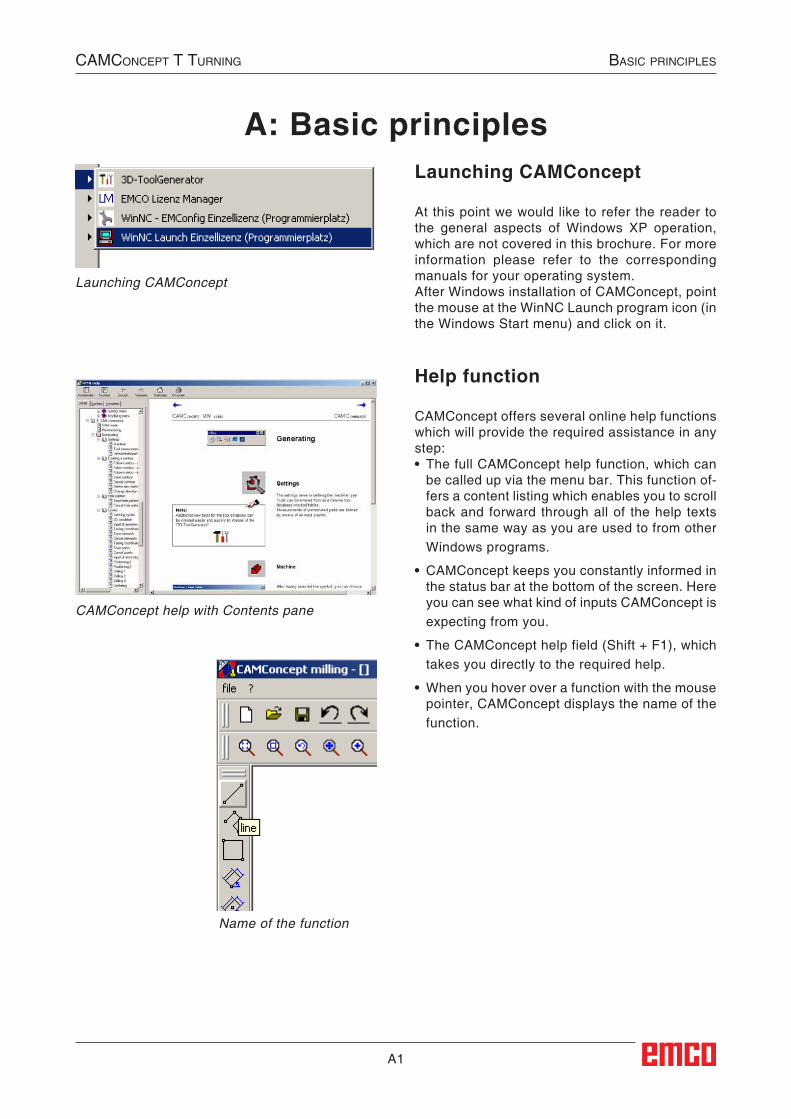
A: Basic principlesLaunching CAMConcept
At this point we would like to refer the reader to the general aspects of Windows XP operation, which are not covered in this brochure. For more information please refer to the corresponding manuals for your operating system.After Windows installation of CAMConcept, point the mouse at the WinNC Launch program icon (in the Windows Start menu) and click on it.
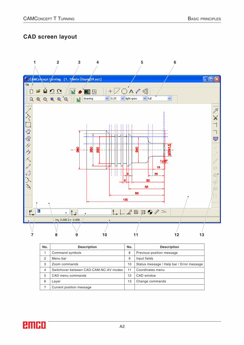
Help function
CAMConcept offers several online help functions which will provide the required assistance in any step:• The full CAMConcept help function, which can
be called up via the menu bar. This function of-fers a content listing which enables you to scroll back and forward through all of the help texts in the same way as you are used to from other Windows programs.
• CAMConcept keeps you constantly informed in the status bar at the bottom of the screen. Here you can see what kind of inputs CAMConcept is expecting from you.
• The CAMConcept help field (Shift + F1), which takes you directly to the required help.
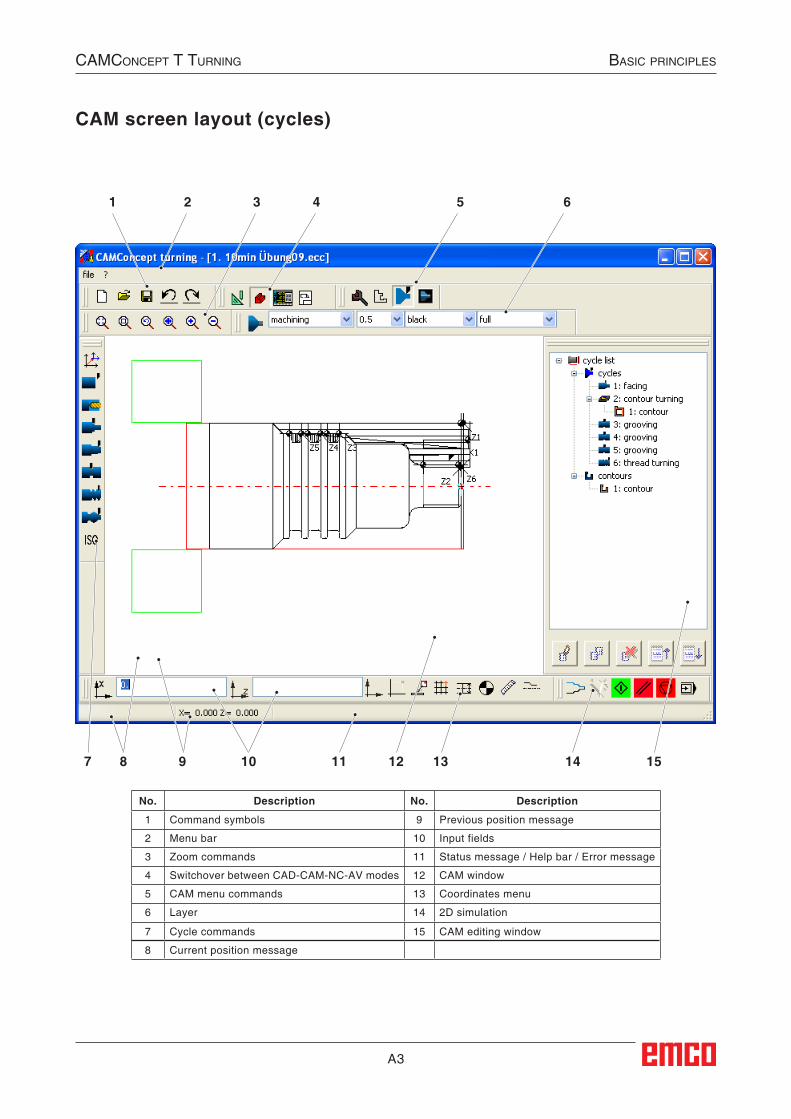
• When you hover over a function with the mouse pointer, CAMConcept displays the name of the function.
CAMConcept help with Contents pane
Name of the function
Launching CAMConcept
A2
1 2 3 4 5 6
7 8 9 10 11 12 13
CAMConCept t turning BAsiC prinCiples
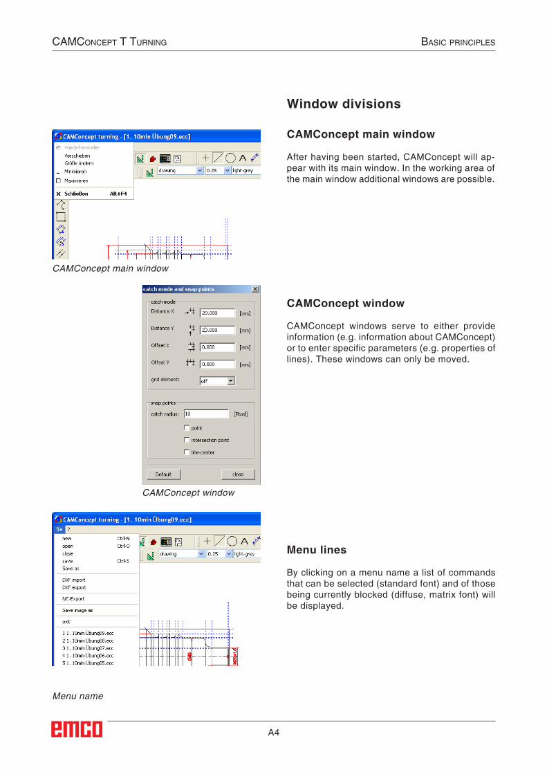
CAD screen layout
No. Description No. Description
1 Command symbols 8 Previous position message
2 Menu bar 9 Input fields
3 Zoom commands 10 Status message / Help bar / Error message
4 Switchover between CAD-CAM-NC-AV modes 11 Coordinates menu
5 CAD menu commands 12 CAD window
6 Layer 13 Change commands
7 Current position message
A3
1 2 3 4 5 6
8 9 10 11 13 14 157 12
CAMConCept t turning BAsiC prinCiples
CAM screen layout (cycles)
No. Description No. Description
1 Command symbols 9 Previous position message
2 Menu bar 10 Input fields
3 Zoom commands 11 Status message / Help bar / Error message
4 Switchover between CAD-CAM-NC-AV modes 12 CAM window
5 CAM menu commands 13 Coordinates menu
6 Layer 14 2D simulation
7 Cycle commands 15 CAM editing window
8 Current position message
A4
Window divisions
CAMConcept main window
After having been started, CAMConcept will ap-pear with its main window. In the working area of the main window additional windows are possible.
CAMConcept main window
CAMConcept window
Menu name
CAMConcept window
CAMConcept windows serve to either provide information (e.g. information about CAMConcept) or to enter specific parameters (e.g. properties of lines). These windows can only be moved.
Menu lines
By clicking on a menu name a list of commands that can be selected (standard font) and of those being currently blocked (diffuse, matrix font) will be displayed.
CAMConCept t turning BAsiC prinCiples
B1
Icon inactive
Icon active
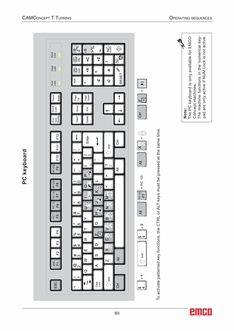
B: Operating sequencesYou can maximize, minimize windows or go back to normal window size by means of the window symbols. Make a double click on the text display of the status line to switch between the normal and the maximized window size.
Command symbolsDisplay of symbolsWhen you have selected a command symbol with the mouse button (which means it is active), the symbol appears shaded.
The symbol will remain active until• the command is carried out (direct command
symbols).• the command is deselected by another one
(menu commands and shift symbols).• the command is cancelled by pressing the
right mouse key.
Note:Press the right mouse button when you wish to return to the respective superordinate menu.It is possible to change the properties of an element later in the CAD mode by means of the right mouse button.
Undo / Redo
Use the symbol "Undo" to cancel the last opera-ting commands.The symbol "Redo" enables to cancel already cancelled operating commands.
CAMConCept t turning operAting sequenCes
B2
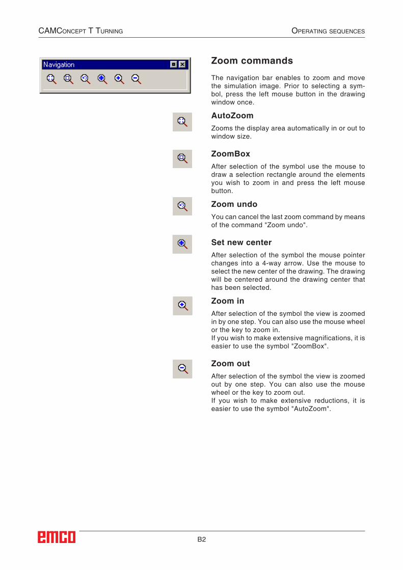
Zoom commands
The navigation bar enables to zoom and move the simulation image. Prior to selecting a sym-bol, press the left mouse button in the drawing window once.
AutoZoomZooms the display area automatically in or out to window size.
ZoomBoxAfter selection of the symbol use the mouse to draw a selection rectangle around the elements you wish to zoom in and press the left mouse button.
Zoom undoYou can cancel the last zoom command by means of the command "Zoom undo".
Set new centerAfter selection of the symbol the mouse pointer changes into a 4-way arrow. Use the mouse to select the new center of the drawing. The drawing will be centered around the drawing center that has been selected.
Zoom inAfter selection of the symbol the view is zoomed in by one step. You can also use the mouse wheel or the key to zoom in.If you wish to make extensive magnifications, it is easier to use the symbol "ZoomBox".
Zoom outAfter selection of the symbol the view is zoomed out by one step. You can also use the mouse wheel or the key to zoom out.If you wish to make extensive reductions, it is easier to use the symbol "AutoZoom".
CAMConCept t turning operAting sequenCes
B3
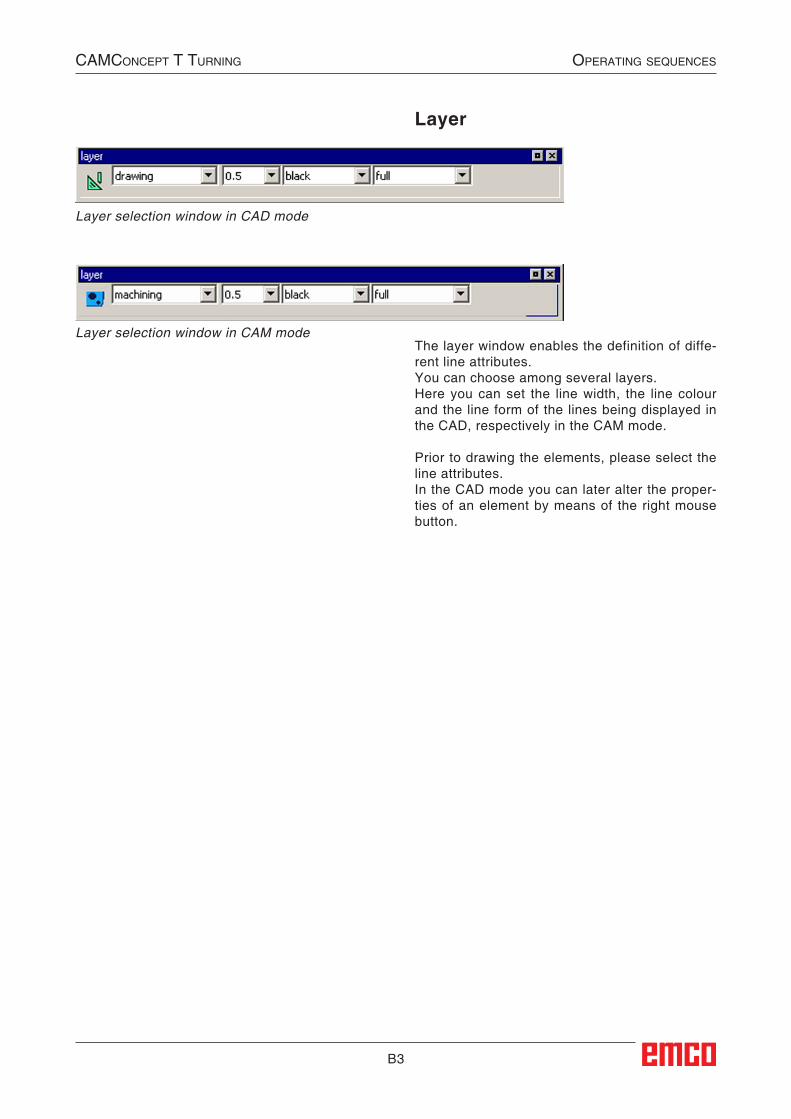
Layer
The layer window enables the definition of diffe-rent line attributes.You can choose among several layers.Here you can set the line width, the line colour and the line form of the lines being displayed in the CAD, respectively in the CAM mode.
Prior to drawing the elements, please select the line attributes.In the CAD mode you can later alter the proper-ties of an element by means of the right mouse button.
CAMConCept t turning operAting sequenCes
Layer selection window in CAD mode
Layer selection window in CAM mode
B4
CAMConCept t turning operAting sequenCes
Calculator in input fields
With the aid of the calculator, mathematical expressions can be calculated directly in an input field.Any number of parenthesis levels can be used in the expressions.To calculate the expressions, press the "Enter" key or exit the input field.
In the event of errors during calculation of a formula, the last entered expression is displayed and CAMConcept outputs an error message.
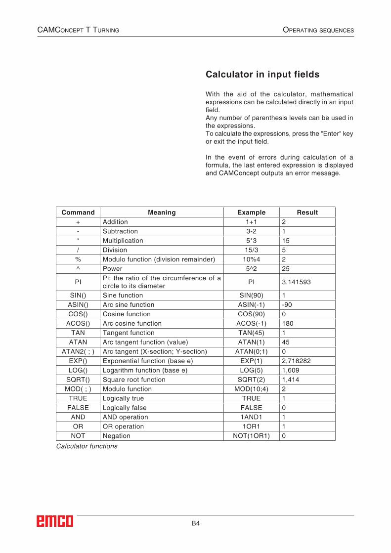
Calculator functions
Command Meaning Example Result+ Addition 1+1 2- Subtraction 3-2 1* Multiplication 5*3 15/ Division 15/3 5
% Modulo function (division remainder) 10%4 2^ Power 5^2 25
PI Pi; the ratio of the circumference of a circle to its diameter PI 3.141593
SIN() Sine function SIN(90) 1ASIN() Arc sine function ASIN(-1) -90COS() Cosine function COS(90) 0
ACOS() Arc cosine function ACOS(-1) 180TAN Tangent function TAN(45) 1
ATAN Arc tangent function (value) ATAN(1) 45ATAN2( ; ) Arc tangent (X-section; Y-section) ATAN(0;1) 0
EXP() Exponential function (base e) EXP(1) 2,718282LOG() Logarithm function (base e) LOG(5) 1,609
SQRT() Square root function SQRT(2) 1,414MOD( ; ) Modulo function MOD(10;4) 2
TRUE Logically true TRUE 1FALSE Logically false FALSE 0AND AND operation 1AND1 1OR OR operation 1OR1 1
NOT Negation NOT(1OR1) 0
##SEC:Taschenrechner##
B5
CAMConCept t turning operAting sequenCes
Alt
Gr
End
Del
ete
Num
Lock
Cap
sLo
ckS
crol
lLo
ck
Num
NC
-S
TAR
T
NC
-S
TOP
RE
SE
T
+C
-C-Z+Z
+X -XDR
YR
UN
SKI
P
OP
TS
TOP
SBL
<% >%
F12
WE
RT
Y
AS
DG
L
Z
Ctrl
Alt
Alt
1!
K
4$5%
O
HJ
F2
Q
= 4
= $
==
4$4$
Ctrl
Alt
ESC
Inse
rtH
ome
Prin
tS
crn
Sys
Rq
Pau
se
Bre
ak
Scr
oll
Lock
F4F1
0F1
1F3
F1JOG
Pag
eU
p
Pag
eD
own
F
F8IN
C 1
000
F9IN
C 10
000
F6INC
10
F7IN
C 1
00
F5INC
1
U
VX
= IN
C 1
00A
ltF7
INC
100
FX
CtrlCap
s Lo
ckTab
2@
/
Ent
er
Shi
ftS
hift
~ `6^
3#7&
0)9(
8*
" ´=+
/?
-
_ ]
]
Shi
ft
: ;
.>,<
MA
UX
NA
UX
BC
PI
7
3
5
PC k
eybo
ard
To a
ctiv
ate
patte
rned
key
func
tions
, the
CTR
L or
ALT
key
s m
ust b
e pr
esse
d at
the
sam
e tim
e.
Not
e:Th
e P
C k
eybo
ard
is o
nly
avai
labl
e fo
r E
MC
O
Con
cept
mac
hine
s.Th
e m
achi
ne f
unct
ions
in t
he n
umer
ical
key
-pa
d ar
e on
ly a
ctiv
e if
NU
M L
ock
is n
ot a
ctiv
e.
B6
CAMConCept t turning operAting sequenCes
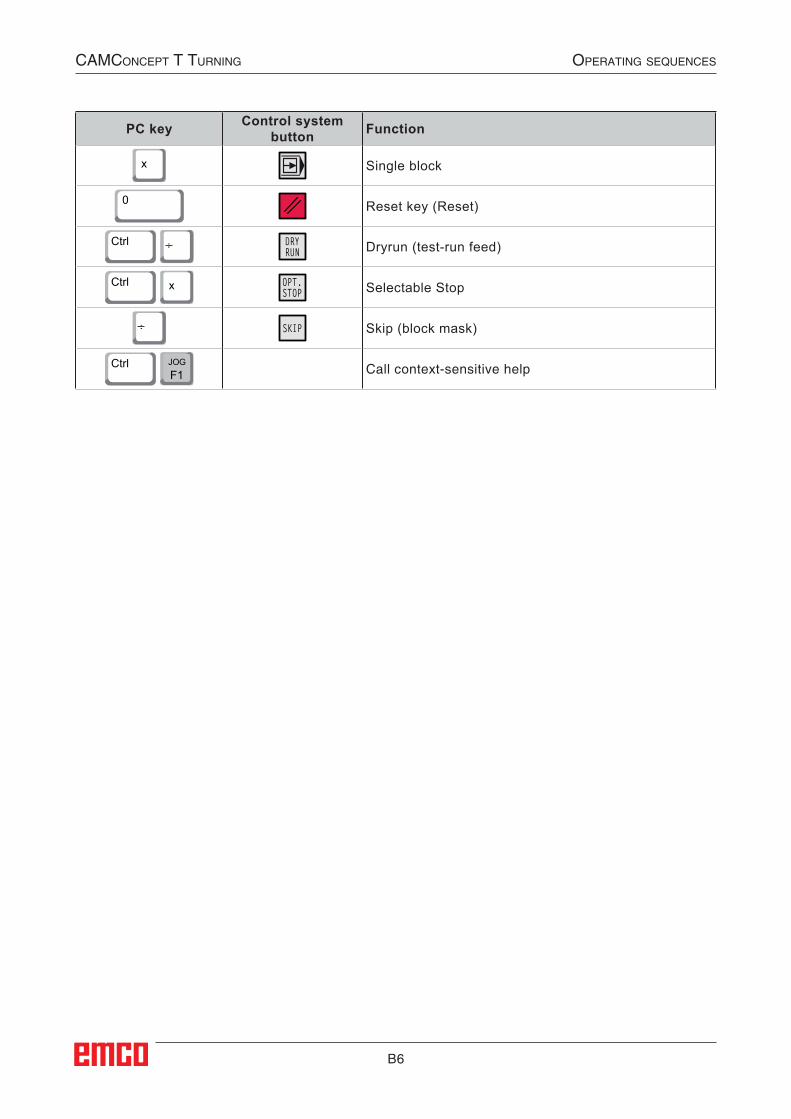
PC key Control system button Function
x Single block
0 Reset key (Reset)
Ctrl
.. DRYRUN Dryrun (test-run feed)
Ctrl
x OPT.STOP Selectable Stop
.. SKIP Skip (block mask)
Ctrl F1
JOGCall context-sensitive help
B7
CAMConCept t turning operAting sequenCes
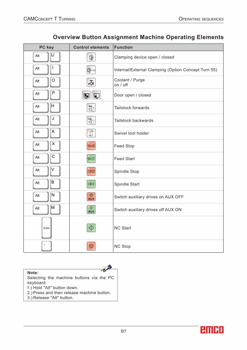
PC key Control elements Function
Alt
U Clamping device open / closed
Alt
I Internal/External Clamping (Option Concept Turn 55)
Alt
O Coolant / Purge on / off
Alt
P
Door open / closed
Alt
H Tailstock forwards
Alt
J Tailstock backwards
Alt
K Swivel tool holder
Alt
X Feed Stop
Alt
C Feed Start
Alt
V Spindle Stop
Alt
B Spindle Start
Alt
N Switch auxiliary drives on AUX OFF
Alt
M Switch auxiliary drives off AUX ON
Enter NC Start
, NC Stop
Note:Selecting the machine buttons via the PC keyboard: 1.) Hold "Alt" button down.2.) Press and then release machine button.3.) Release "Alt" button.
Overview Button Assignment Machine Operating Elements
B8
CAMConCept t turning operAting sequenCes
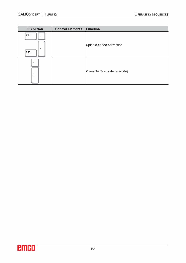
PC button Control elements Function
Ctrl
-
Ctrl
+Spindle speed correction
-
+Override (feed rate override)
C1
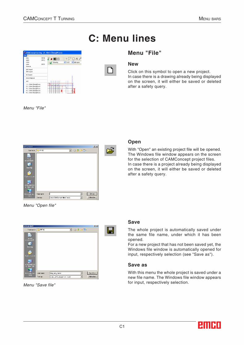
C: Menu linesMenu "File"
NewClick on this symbol to open a new project.In case there is a drawing already being displayed on the screen, it will either be saved or deleted after a safety query.
OpenWith "Open" an existing project file will be opened.The Windows file window appears on the screen for the selection of CAMConcept project files.In case there is a project already being displayed on the screen, it will either be saved or deleted after a safety query.
SaveThe whole project is automatically saved under the same file name, under which it has been opened.For a new project that has not been saved yet, the Windows file window is automatically opened for input, respectively selection (see "Save as").
Save asWith this menu the whole project is saved under a new file name. The Windows file window appears for input, respectively selection.
Menu "File"
Menu "Open file"
Menu "Save file"
CAMConCept t turning Menu bArs
C2
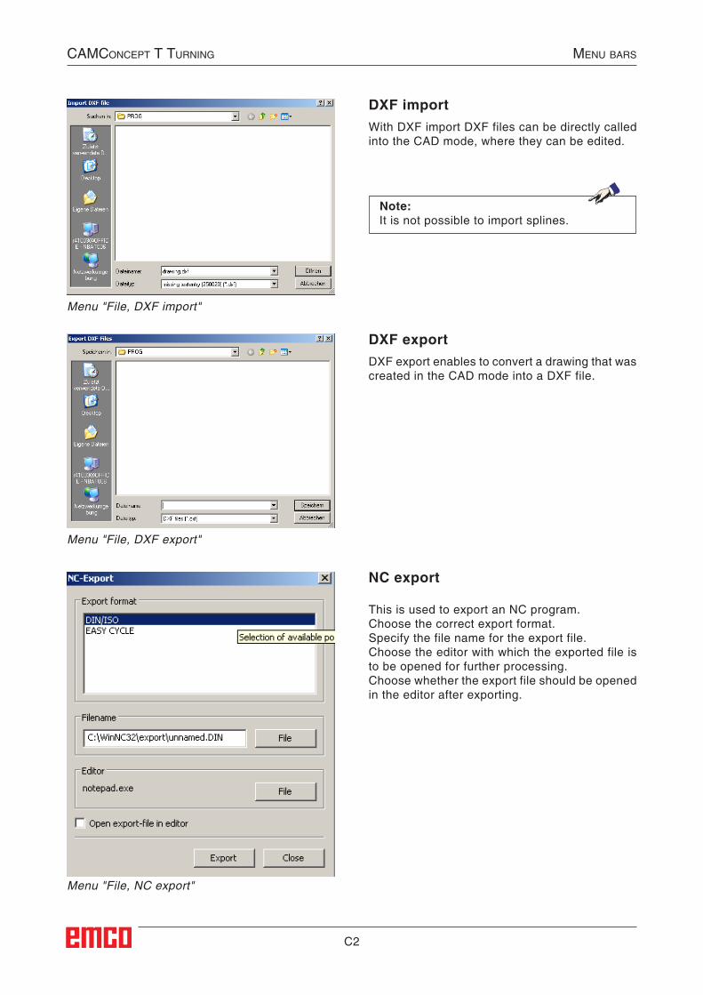
DXF importWith DXF import DXF files can be directly called into the CAD mode, where they can be edited.
Menu "File, NC export"
Menu "File, DXF export"
Menu "File, DXF import"
DXF exportDXF export enables to convert a drawing that was created in the CAD mode into a DXF file.
CAMConCept t turning Menu bArs
NC export
This is used to export an NC program.Choose the correct export format.Specify the file name for the export file.Choose the editor with which the exported file is to be opened for further processing.Choose whether the export file should be opened in the editor after exporting.
Note:It is not possible to import splines.
##SEC:Export##
C3
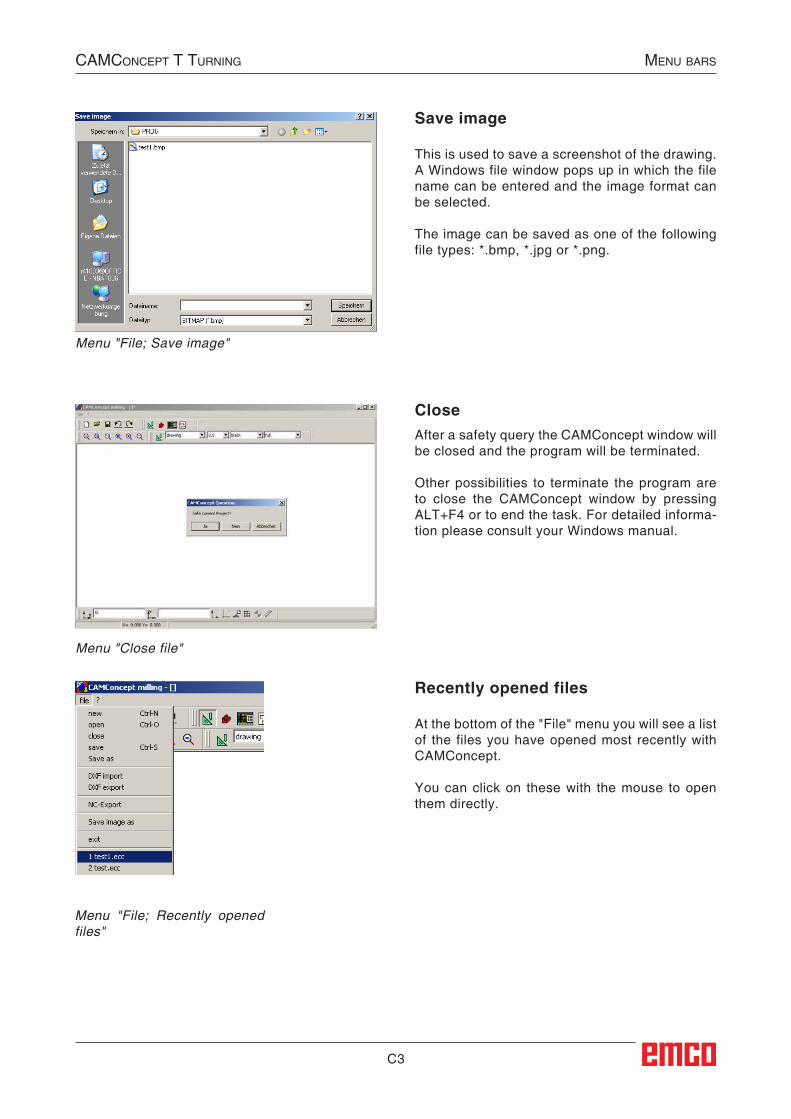
CloseAfter a safety query the CAMConcept window will be closed and the program will be terminated.
Other possibilities to terminate the program are to close the CAMConcept window by pressing ALT+F4 or to end the task. For detailed informa-tion please consult your Windows manual.
Menu "Close file"
CAMConCept t turning Menu bArs
Save image
This is used to save a screenshot of the drawing. A Windows file window pops up in which the file name can be entered and the image format can be selected.
The image can be saved as one of the following file types: *.bmp, *.jpg or *.png.
Menu "File; Save image"
Recently opened files
At the bottom of the "File" menu you will see a list of the files you have opened most recently with CAMConcept.
You can click on these with the mouse to open them directly.
Menu "File; Recently opened files"
C4
CAMConCept t turning Menu bArs
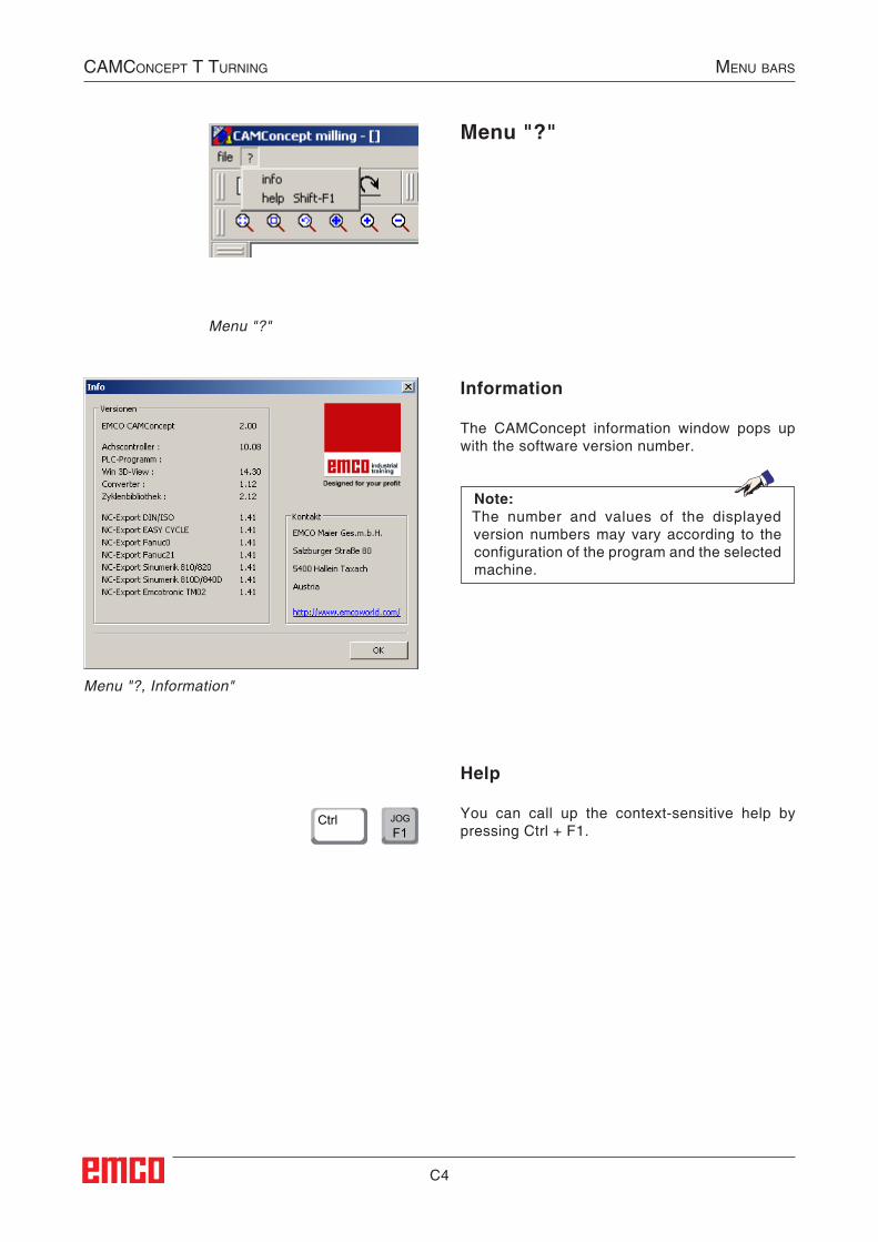
Menu "?"
Help
You can call up the context-sensitive help by pressing Ctrl + F1.
Menu "?"
Menu "?, Information"
Information
The CAMConcept information window pops up with the software version number.
Note:The number and values of the displayed version numbers may vary according to the configuration of the program and the selected machine.
F1JOGCtrl
D1
D: CAD Commands
CAD mode
The CAD command symbols are activated by clik-king on the shift symbol "CAD". The CAD mode will remain active until it is deselected by CAM, NC or operations scheduling. After the start of CAMConcept the CAD mode will be automatically activated.
The zoom commands are described in chapter B.
Note:Please confirm all value entries with "ENTER".
Note:You return to the respective superordinate menu by pressing the right mouse button.In the CAD mode the properties of an element can be changed later by means of the right mouse button.
CAMConCept t turning CAD CoMMAnDs
Redraw
The screen is redrawn after the F5 key is pressed.After using the "Delete" or "Change" functions, it is possible that some lines on the screen are only displayed incompletely. In this case you should use the "Redraw" function or the zoom commands in order to refresh the screen display.
##CAD:Modus##
D2
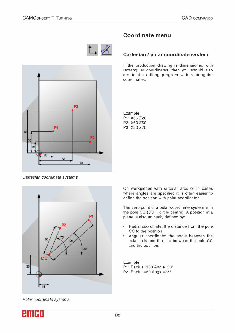
Polar coordinate systems
Cartesian coordinate systems
CAMConCept t turning CAD CoMMAnDs
Coordinate menu
Cartesian / polar coordinate system
If the production drawing is dimensioned with rectangular coordinates, then you should also create the editing program with rectangular coordinates.
Example:P1: X35 Z20P2: X60 Z50P3: X20 Z70
On workpieces with circular arcs or in cases where angles are specified it is often easier to define the position with polar coordinates.
The zero point of a polar coordinate system is in the pole CC (CC = circle centre). A position in a plane is also uniquely defined by:
• Radial coordinate: the distance from the pole CC to the position
• Angular coordinate: the angle between the polar axis and the line between the pole CC and the position.
Example:P1: Radius=100 Angle=30°P2: Radius=60 Angle=75°
D3
CAMConCept t turning CAD CoMMAnDs
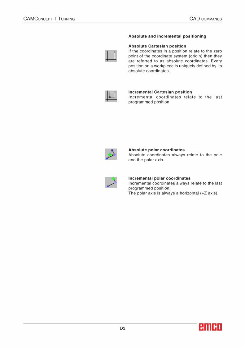
Absolute and incremental positioning
Absolute Cartesian positionIf the coordinates in a position relate to the zero point of the coordinate system (origin) then they are referred to as absolute coordinates. Every position on a workpiece is uniquely defined by its absolute coordinates.
Incremental Cartesian positionIncremental coordinates relate to the last programmed position.
Absolute polar coordinatesAbsolute coordinates always relate to the pole and the polar axis.
Incremental polar coordinatesIncremental coordinates always relate to the last programmed position.The polar axis is always a horizontal (+Z axis).
D4
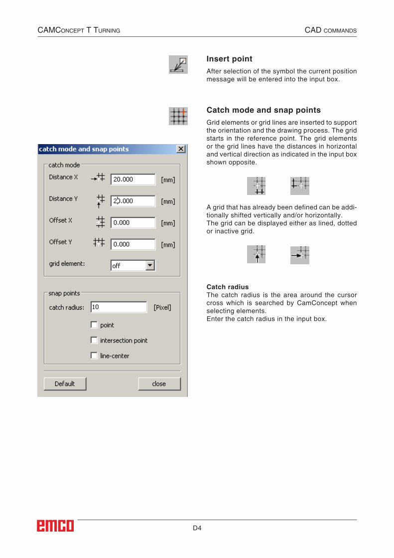
Insert pointAfter selection of the symbol the current position message will be entered into the input box.
A grid that has already been defined can be addi-tionally shifted vertically and/or horizontally.The grid can be displayed either as lined, dotted or inactive grid.
Catch radiusThe catch radius is the area around the cursor cross which is searched by CamConcept when selecting elements.Enter the catch radius in the input box.
Catch mode and snap pointsGrid elements or grid lines are inserted to support the orientation and the drawing process. The grid starts in the reference point. The grid elements or the grid lines have the distances in horizontal and vertical direction as indicated in the input box shown opposite.
CAMConCept t turning CAD CoMMAnDs
##SEC:Fangraster_und_Fangpunkte##
D5
Set zero pointThe CAD zero point is automatically set in the center of the drawing window.This function enables to shift the zero point and thus the coordinate system from its present po-sition.
After selection of the symbol use the left mouse button to position the new zero point at the re-quired position.
Cancel zero pointWhen you select this symbol, the zero point that has been set will be cancelled
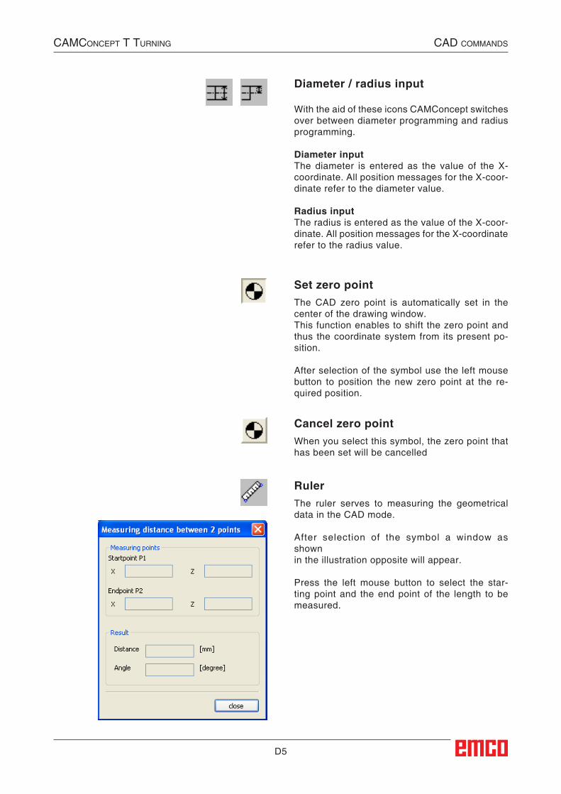
RulerThe ruler serves to measuring the geometrical data in the CAD mode.
After selection of the symbol a window as shown in the illustration opposite will appear.
Press the left mouse button to select the star-ting point and the end point of the length to be measured.
CAMConCept t turning CAD CoMMAnDs
Diameter / radius input
With the aid of these icons CAMConcept switches over between diameter programming and radius programming.
Diameter inputThe diameter is entered as the value of the X-coordinate. All position messages for the X-coor-dinate refer to the diameter value.
Radius inputThe radius is entered as the value of the X-coor-dinate. All position messages for the X-coordinate refer to the radius value.
##SEC:Zeichenlineal##
D6
CAMConCept t turning CAD CoMMAnDs
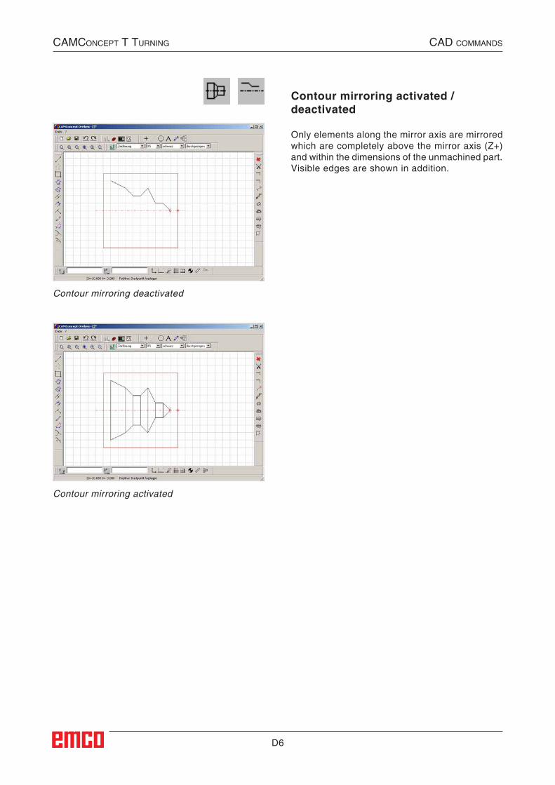
Contour mirroring activated / deactivated
Only elements along the mirror axis are mirrored which are completely above the mirror axis (Z+) and within the dimensions of the unmachined part. Visible edges are shown in addition.
Contour mirroring deactivated
Contour mirroring activated

D7
CAMConCept t turning CAD CoMMAnDs
D8
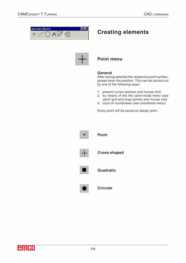
Point
Point menu
Cross-shaped
Quadratic
Circular
GeneralAfter having selected the respective point symbol, please enter the position. This can be carried out by one of the following ways:
1. present cursor position and mouse click2. by means of the the catch-mode menu (see
catch grid and snap points) and mouse click3. input of coordinates (see coordinate menu)
Every point will be saved as design point.
Creating elements
CAMConCept t turning CAD CoMMAnDs
##CAD:Punktmenue##
D9
1 2 3
Line menu
Drawing a line
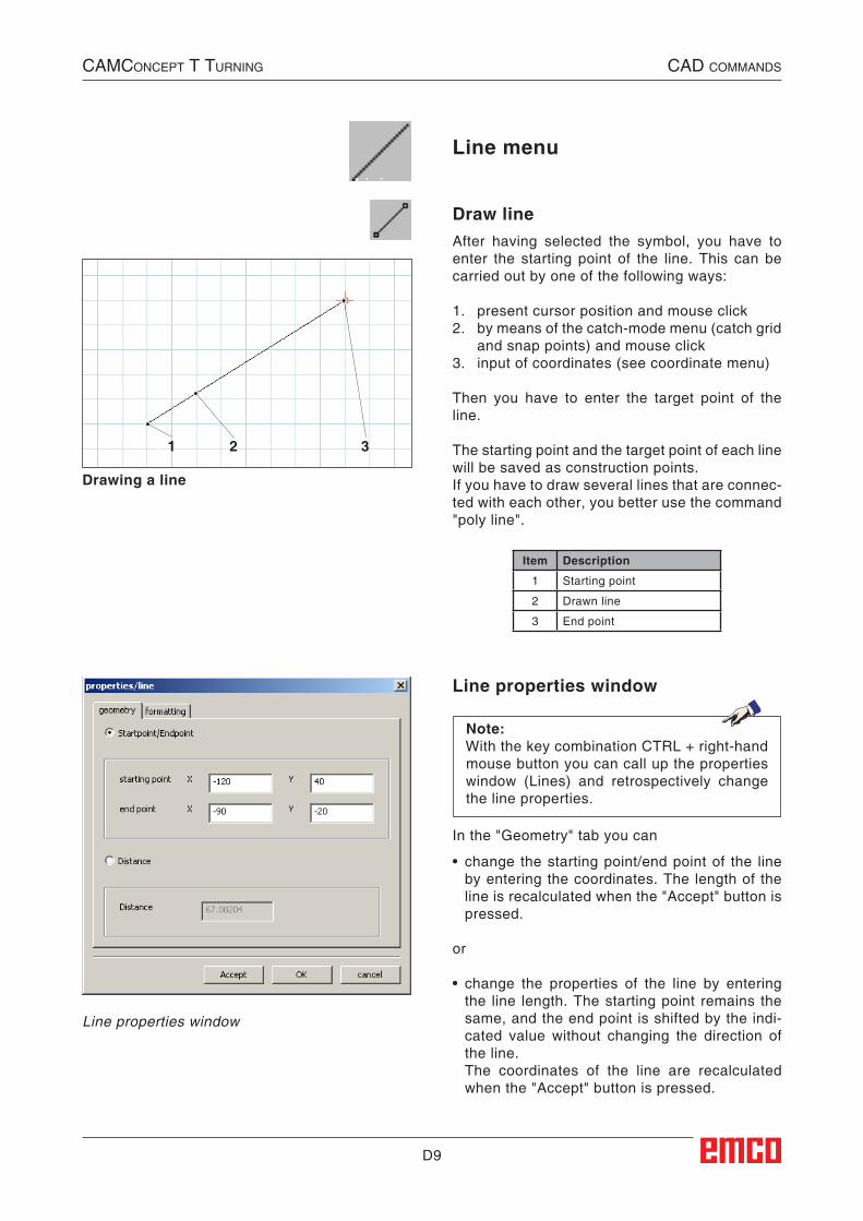
Draw lineAfter having selected the symbol, you have to enter the starting point of the line. This can be carried out by one of the following ways:
1. present cursor position and mouse click2. by means of the catch-mode menu (catch grid
and snap points) and mouse click3. input of coordinates (see coordinate menu)
Then you have to enter the target point of the line.
The starting point and the target point of each line will be saved as construction points.If you have to draw several lines that are connec-ted with each other, you better use the command "poly line".
CAMConCept t turning CAD CoMMAnDs
Line properties window
Note:With the key combination CTRL + right-hand mouse button you can call up the properties window (Lines) and retrospectively change the line properties.
In the "Geometry" tab you can
• change the starting point/end point of the line by entering the coordinates. The length of the line is recalculated when the "Accept" button is pressed.
or
• change the properties of the line by entering the line length. The starting point remains the same, and the end point is shifted by the indi-cated value without changing the direction of the line.
The coordinates of the line are recalculated when the "Accept" button is pressed.
Line properties window
Item Description
1 Starting point
2 Drawn line
3 End point
##CAD:Linie_zeichnen##
##CAD:Linienmenue##
D10
1 2
3
4
5 6
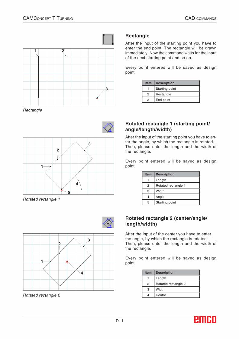
Poly line
After the input of the starting point you have to enter the first target point. The first line of the poly line (polygon) will be drawn immediately. Now the command waits for the input of the next target point and so on.
Every point entered will be saved as design point.
The command is selfholding and must be inter-rupted (other command symbol, or press right mouse button).
Poly line
CAMConCept t turning CAD CoMMAnDs
Item Description
1 Starting point
2 Point 1
3 Point 2
4 Polyline
5 Point 3
6 Point 4
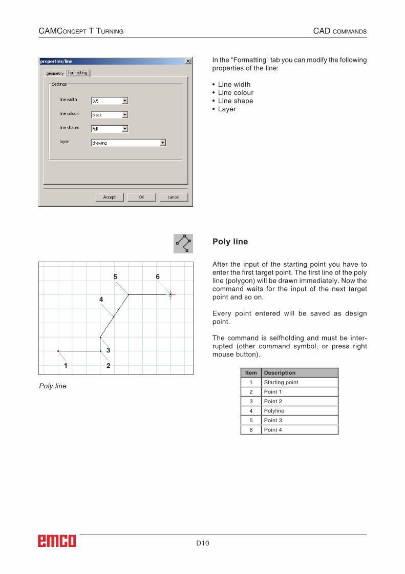
In the "Formatting" tab you can modify the following properties of the line:
• Line width• Line colour• Line shape• Layer
##CAD:Linienzug##
D11
1 2
3
1
23
4
5
23
4
1
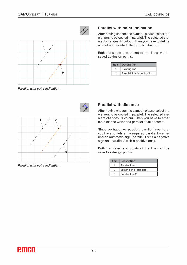
RectangleAfter the input of the starting point you have to enter the end point. The rectangle will be drawn immediately. Now the command waits for the input of the next starting point and so on.
Every point entered will be saved as design point.
Rotated rectangle 1 (starting point/angle/length/width)After the input of the starting point you have to en-ter the angle, by which the rectangle is rotated.Then, please enter the length and the width of the rectangle.
Every point entered will be saved as design point.
Rotated rectangle 2 (center/angle/length/width)
After the input of the center you have to enter the angle, by which the rectangle is rotated.Then, please enter the length and the width of the rectangle.
Every point entered will be saved as design point.
Rectangle
Rotated rectangle 2
Rotated rectangle 1
CAMConCept t turning CAD CoMMAnDs
Item Description
1 Starting point
2 Rectangle
3 End point
Item Description
1 Length
2 Rotated rectangle 1
3 Width
4 Angle
5 Starting point
Item Description
1 Length
2 Rotated rectangle 2
3 Width
4 Centre
##CAD:Rechteck##
##CAD:Gedrehtes_Rechteck_1##
##CAD:Gedrehtes_Rechteck_2##
D12
1
2
1 2
3
Parallel with point indication
Parallel with point indication
Parallel with point indicationAfter having chosen the symbol, please select the element to be copied in parallel. The selected ele-ment changes its colour. Then you have to define a point across which the parallel shall run.
Both translated end points of the lines will be saved as design points.
Parallel with distanceAfter having chosen the symbol, please select the element to be copied in parallel. The selected ele-ment changes its colour. Then you have to enter the distance which the parallel shall observe.
Since we have two possible parallel lines here, you have to define the required parallel by ente-ring an arithmetic sign (parallel 1 with a negative sign and parallel 2 with a positive one).
Both translated end points of the lines will be saved as design points.
CAMConCept t turning CAD CoMMAnDs
Item Description
1 Existing line
2 Parallel line through point
Item Description
1 Parallel line 1
2 Existing line (selected)
3 Parallel line 2
##CAD:Parallele_mit_Punktangabe##
##CAD:Parallele_mit_Abstand##
D13
1
2
1 2
3
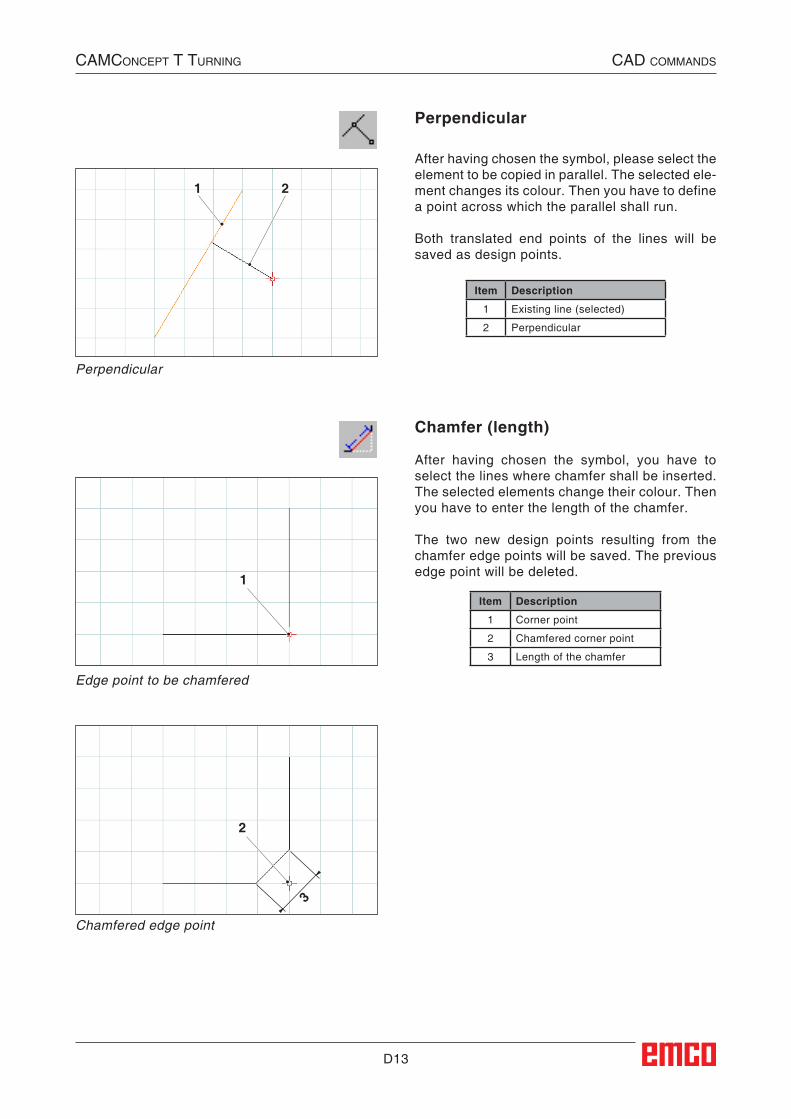
Perpendicular
Perpendicular
After having chosen the symbol, please select the element to be copied in parallel. The selected ele-ment changes its colour. Then you have to define a point across which the parallel shall run.
Both translated end points of the lines will be saved as design points.
Chamfer (length)
After having chosen the symbol, you have to select the lines where chamfer shall be inserted. The selected elements change their colour. Then you have to enter the length of the chamfer.
The two new design points resulting from the chamfer edge points will be saved. The previous edge point will be deleted.
Edge point to be chamfered
Chamfered edge point
CAMConCept t turning CAD CoMMAnDs
Item Description
1 Existing line (selected)
2 Perpendicular
Item Description
1 Corner point
2 Chamfered corner point
3 Length of the chamfer
##CAD:Normale##
##CAD:Fase_Laenge##

D14
1
2
3
Chamfer (distance/distance)
After having chosen the symbol, you have to select the lines where the chamfer shall be inser-ted. The selected elements change their colour. Then you have to enter the length of the chamfer in axis direction.
The two new design points resulting from the chamfer edge points will be saved.
Edge point to be chamfered
Chamfered edge point
CAMConCept t turning CAD CoMMAnDs
Item Description
1 Corner point
2 Chamfered corner point
3 Length of the chamfer in the direction of the axis
##CAD:Fase_Abstand_Abstand##
D15
1 2
3
4
3
2
1
Tangent point - circle
Possible tangents
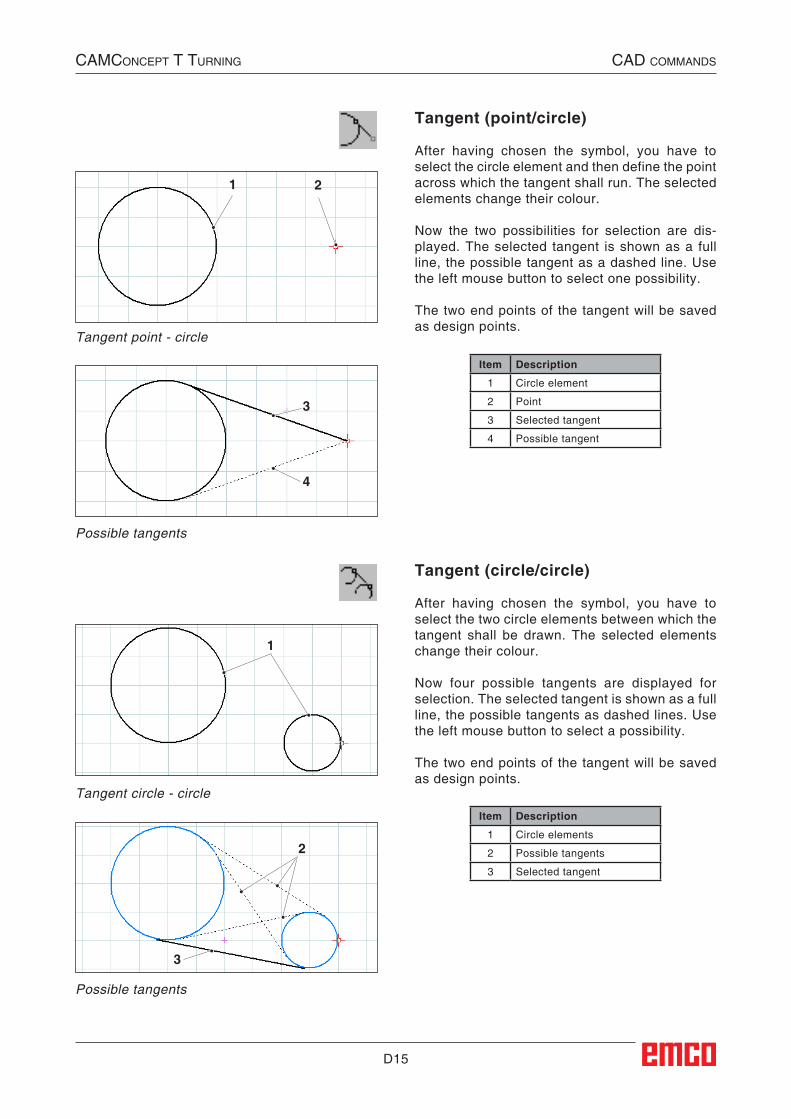
Tangent (point/circle)
After having chosen the symbol, you have to select the circle element and then define the point across which the tangent shall run. The selected elements change their colour.
Now the two possibilities for selection are dis-played. The selected tangent is shown as a full line, the possible tangent as a dashed line. Use the left mouse button to select one possibility.
The two end points of the tangent will be saved as design points.
Tangent circle - circle
Possible tangents
Tangent (circle/circle)
After having chosen the symbol, you have to select the two circle elements between which the tangent shall be drawn. The selected elements change their colour.
Now four possible tangents are displayed for selection. The selected tangent is shown as a full line, the possible tangents as dashed lines. Use the left mouse button to select a possibility.
The two end points of the tangent will be saved as design points.
CAMConCept t turning CAD CoMMAnDs
Item Description
1 Circle element
2 Point
3 Selected tangent
4 Possible tangent
Item Description
1 Circle elements
2 Possible tangents
3 Selected tangent
##CAD:Tangente_Punkt_Kreis##
##CAD:Tangente_Kreis_Kreis##
D16
1
2
3
Circle menu
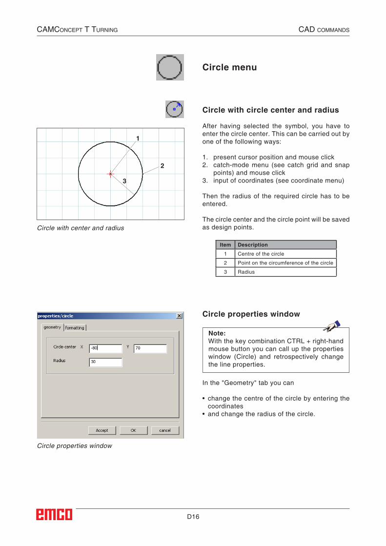
Circle with circle center and radius
After having selected the symbol, you have to enter the circle center. This can be carried out by one of the following ways:
1. present cursor position and mouse click2. catch-mode menu (see catch grid and snap
points) and mouse click3. input of coordinates (see coordinate menu)
Then the radius of the required circle has to be entered.
The circle center and the circle point will be saved as design points.Circle with center and radius
CAMConCept t turning CAD CoMMAnDs
Circle properties window
Note:With the key combination CTRL + right-hand mouse button you can call up the properties window (Circle) and retrospectively change the line properties.
In the "Geometry" tab you can
• change the centre of the circle by entering the coordinates
• and change the radius of the circle.
Circle properties window
Item Description
1 Centre of the circle
2 Point on the circumference of the circle
3 Radius
##CAD:Kreis_mit_Mittelpunkt_und_Radius##
##CAD:Kreismenue##
D17
1
2
Circle with circle point and center
CAMConCept t turning CAD CoMMAnDs
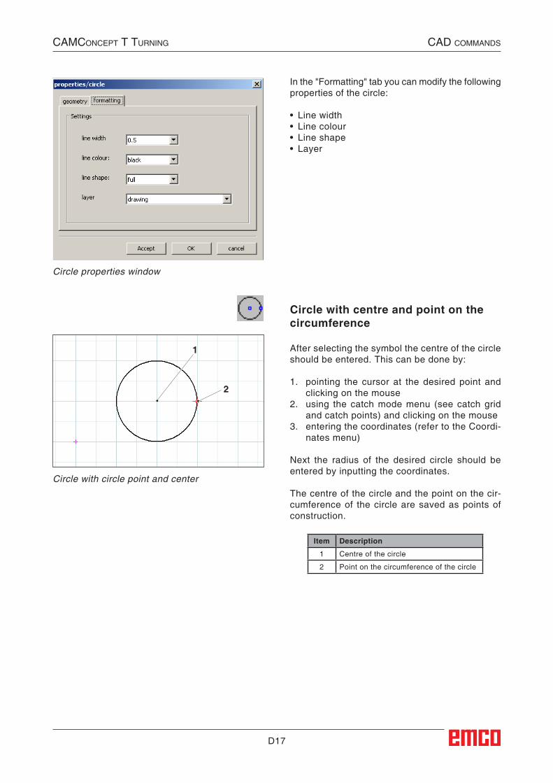
In the "Formatting" tab you can modify the following properties of the circle:
• Line width• Line colour• Line shape• Layer
Circle properties window
Circle with centre and point on the circumference
After selecting the symbol the centre of the circle should be entered. This can be done by:
1. pointing the cursor at the desired point and clicking on the mouse
2. using the catch mode menu (see catch grid and catch points) and clicking on the mouse
3. entering the coordinates (refer to the Coordi-nates menu)
Next the radius of the desired circle should be entered by inputting the coordinates.
The centre of the circle and the point on the cir-cumference of the circle are saved as points of construction.
Item Description
1 Centre of the circle
2 Point on the circumference of the circle
##CAD:Kreis_mit_Kreis_und_Mittelpunkt##
D18
1 2
1
2
3
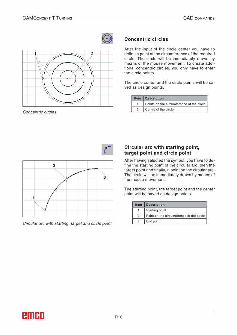
Concentric circles
After the input of the circle center you have to define a point at the circumference of the required circle. The circle will be immediately drawn by means of the mouse movement. To create addi-tional concentric circles, you only have to enter the circle points.
The circle center and the circle points will be sa-ved as design points.
Circular arc with starting point, target point and circle pointAfter having selected the symbol, you have to de-fine the starting point of the circular arc, then the target point and finally, a point on the circular arc. The circle will be immediately drawn by means of the mouse movement.
The starting point, the target point and the center point will be saved as design points.
Circular arc with starting, target and circle point
CAMConCept t turning CAD CoMMAnDs
Concentric circles
Item Description
1 Points on the circumference of the circle
2 Centre of the circle
Item Description
1 Starting point
2 Point on the circumference of the circle
3 End point
##CAD:Konzentrische_Kreise##
##CAD:Kreisbogen_mit_Start_Ziel_und_Kreispunkt##
D19
1
2
12
3 54
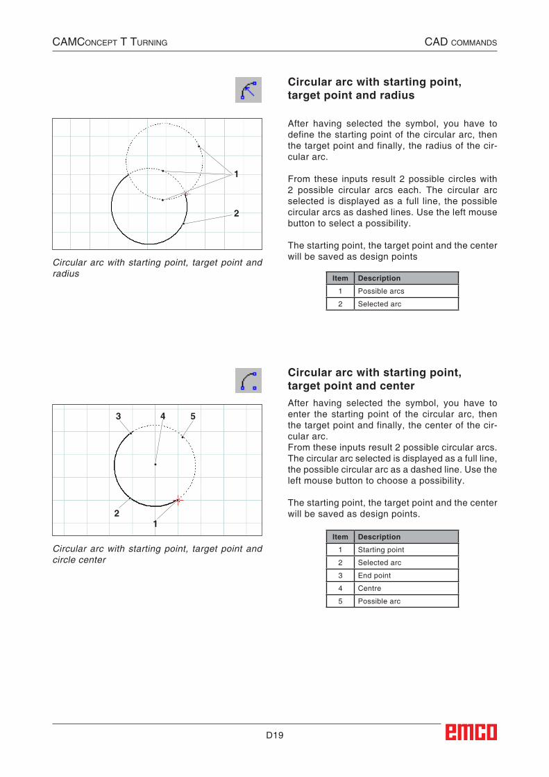
Circular arc with starting point, target point and radius
After having selected the symbol, you have to define the starting point of the circular arc, then the target point and finally, the radius of the cir-cular arc.
From these inputs result 2 possible circles with 2 possible circular arcs each. The circular arc selected is displayed as a full line, the possible circular arcs as dashed lines. Use the left mouse button to select a possibility.
The starting point, the target point and the center will be saved as design points
Circular arc with starting point, target point and centerAfter having selected the symbol, you have to enter the starting point of the circular arc, then the target point and finally, the center of the cir-cular arc.From these inputs result 2 possible circular arcs. The circular arc selected is displayed as a full line, the possible circular arc as a dashed line. Use the left mouse button to choose a possibility.
The starting point, the target point and the center will be saved as design points.
Circular arc with starting point, target point and circle center
Circular arc with starting point, target point and radius
CAMConCept t turning CAD CoMMAnDs
Item Description
1 Possible arcs
2 Selected arc
Item Description
1 Starting point
2 Selected arc
3 End point
4 Centre
5 Possible arc
##CAD:Kreisbogen_mit_Start_Zielpunkt_und_Radius##
##CAD:Kreisbogen_mit_Start_Ziel_und_Mittelpunkt##
D20
1
23
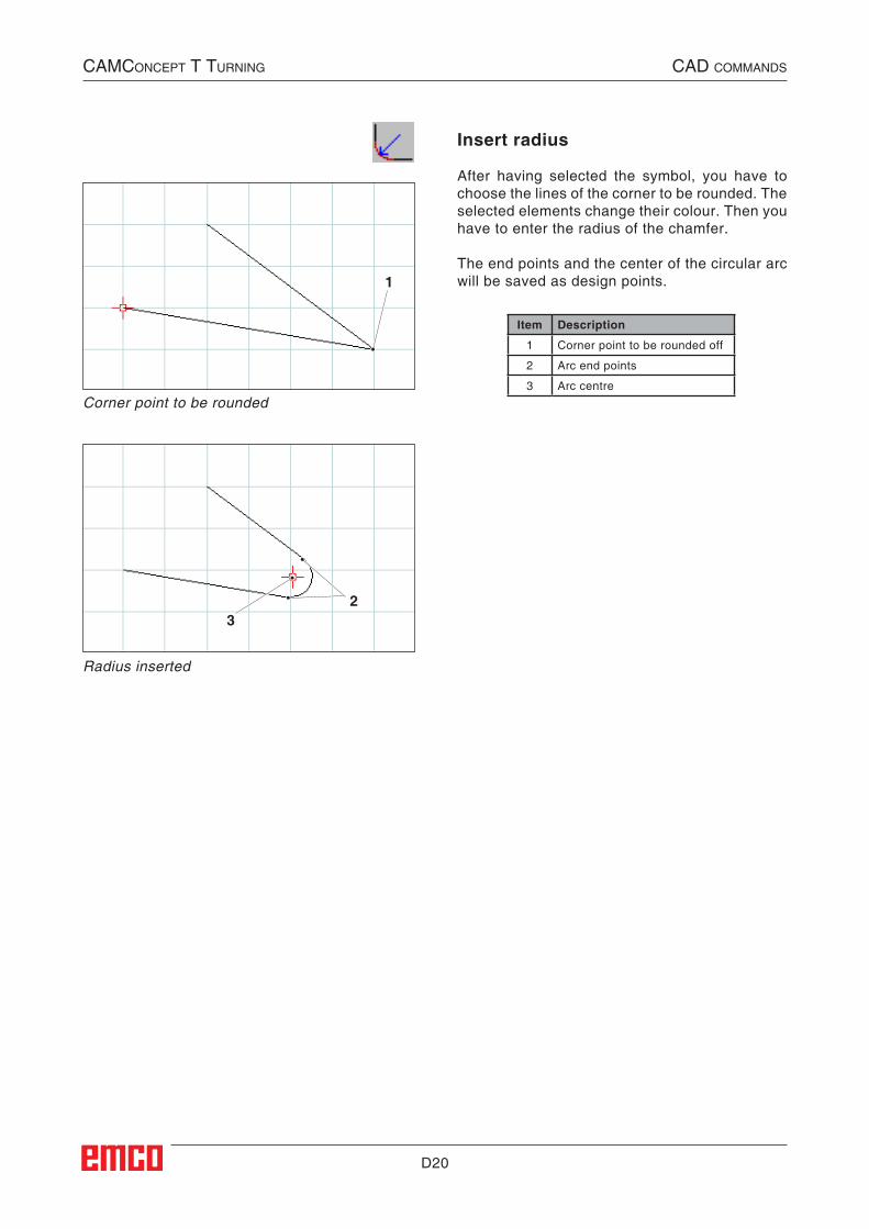
Insert radius
After having selected the symbol, you have to choose the lines of the corner to be rounded. The selected elements change their colour. Then you have to enter the radius of the chamfer.
The end points and the center of the circular arc will be saved as design points.
Corner point to be rounded
Radius inserted
CAMConCept t turning CAD CoMMAnDs
Item Description
1 Corner point to be rounded off
2 Arc end points
3 Arc centre
##CAD:Radius_einfuegen##
D21
1
2
CAMConCept t turning CAD CoMMAnDs
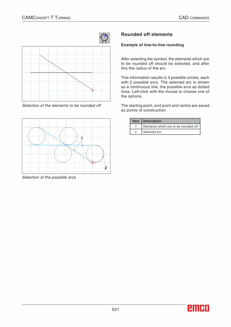
Rounded off elements
Example of line-to-line rounding
After selecting the symbol, the elements which are to be rounded off should be selected, and after this the radius of the arc.
This information results in 4 possible circles, each with 2 possible arcs. The selected arc is shown as a continuous line, the possible arcs as dotted lines. Left-click with the mouse to choose one of the options.
The starting point, end point and centre are saved as points of construction.
Selection of the elements to be rounded off
Selection of the possible arcs
Item Description
1 Elements which are to be rounded off
2 Selected arc
##CAD:Verrunden_von_Elementen##
D22
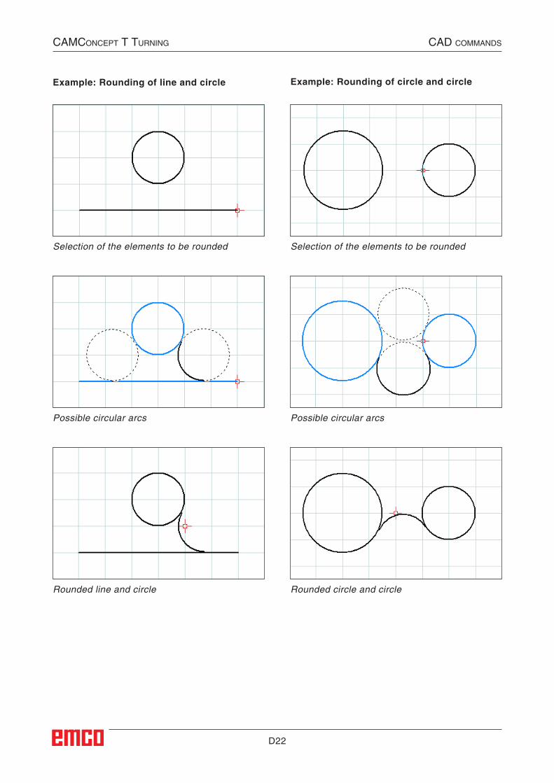
Selection of the elements to be rounded
Example: Rounding of line and circle
Possible circular arcs
Rounded line and circle
Selection of the elements to be rounded
Possible circular arcs
Rounded circle and circle
Example: Rounding of circle and circle
CAMConCept t turning CAD CoMMAnDs
D23
Auswahl der möglichen Kreisbögen
CAMConCept t turning CAD CoMMAnDs
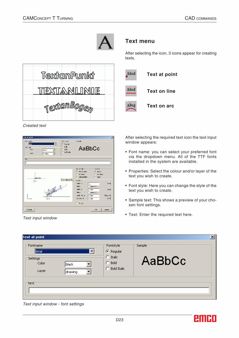
Text menu
After selecting the icon, 3 icons appear for creating texts.
Created text
Text at point
Text on line
Text on arc
After selecting the required text icon the text input window appears:
• Font name: you can select your preferred font via the dropdown menu. All of the TTF fonts installed in the system are available.
• Properties: Select the colour and/or layer of the text you wish to create.
• Font style: Here you can change the style of the text you wish to create.
• Sample text: This shows a preview of your cho-sen font settings.
• Text: Enter the required text here.Text input window
Text input window - font settings
##CAD:Textmenue##
##CAD:Text_an_Punkt##
##CAD:Text_an_Linie##
##CAD:Text_an_Bogen##
D24
CAMConCept t turning CAD CoMMAnDs
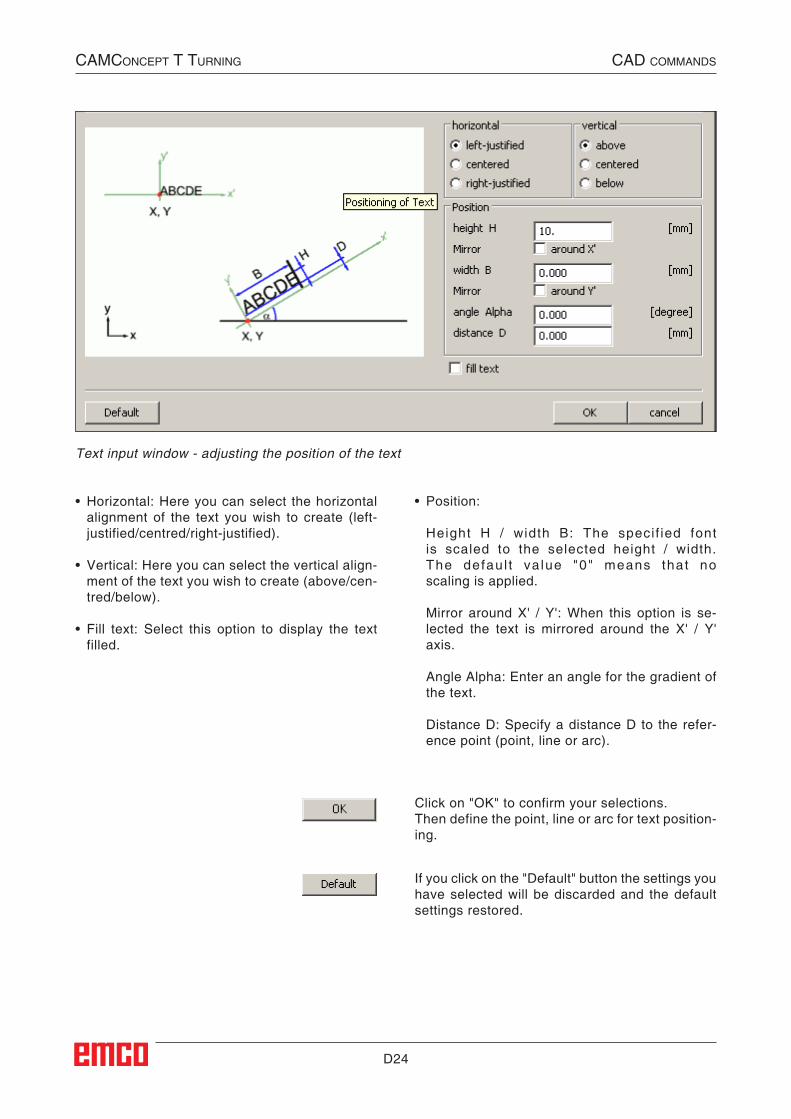
Text input window - adjusting the position of the text
• Horizontal: Here you can select the horizontal alignment of the text you wish to create (left-justified/centred/right-justified).
• Vertical: Here you can select the vertical align-ment of the text you wish to create (above/cen-tred/below).
• Fill text: Select this option to display the text filled.
• Position:
Height H / width B: The specif ied font is scaled to the selected height / width. The defau l t va lue "0" means that no scaling is applied.
Mirror around X' / Y': When this option is se-lected the text is mirrored around the X' / Y' axis.
Angle Alpha: Enter an angle for the gradient of the text.
Distance D: Specify a distance D to the refer-ence point (point, line or arc).
Click on "OK" to confirm your selections.Then define the point, line or arc for text position-ing.
If you click on the "Default" button the settings you have selected will be discarded and the default settings restored.
D25
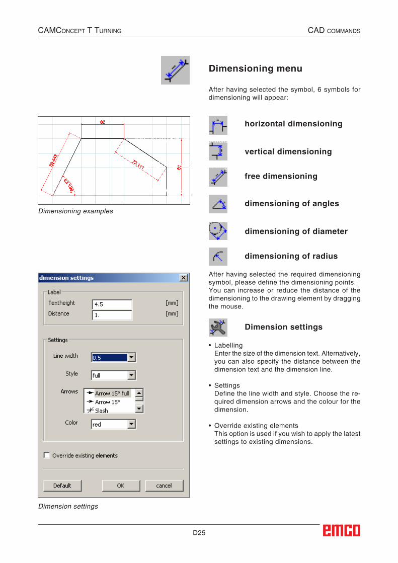
Dimensioning menu
After having selected the symbol, 6 symbols for dimensioning will appear:
Dimensioning examples
horizontal dimensioning
vertical dimensioning
free dimensioning
dimensioning of angles
dimensioning of diameter
dimensioning of radius
After having selected the required dimensioning symbol, please define the dimensioning points.You can increase or reduce the distance of the dimensioning to the drawing element by dragging the mouse.
CAMConCept t turning CAD CoMMAnDs
Dimension settings
Dimension settings
• Labelling Enter the size of the dimension text. Alternatively,
you can also specify the distance between the dimension text and the dimension line.
• Settings Define the line width and style. Choose the re-
quired dimension arrows and the colour for the dimension.
• Override existing elements This option is used if you wish to apply the latest
settings to existing dimensions.
##CAD:Bemaßungseinstellungen##
##CAD:Bemaßungsmenue##
##CAD:Horizontale_Bemaßung##
##CAD:Vertikale_Bemaßung##
##CAD:Freie_Bemaßung##
##CAD:Winkel_Bemaßung##
##CAD:Durchmesser_Bemaßung##
##CAD:Radius_Bemaßung##
D26
CAMConCept t turning CAD CoMMAnDs
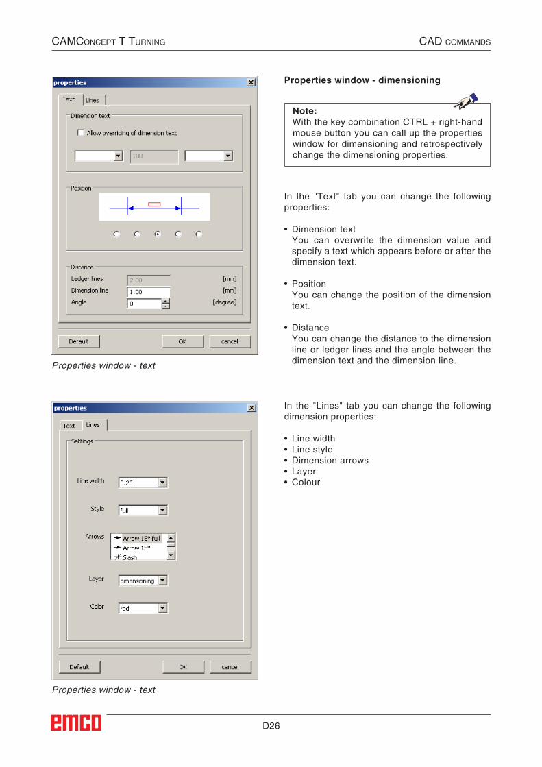
Properties window - text
Properties window - text
Properties window - dimensioning
Note:With the key combination CTRL + right-hand mouse button you can call up the properties window for dimensioning and retrospectively change the dimensioning properties.
In the "Text" tab you can change the following properties:
• Dimension text You can overwrite the dimension value and
specify a text which appears before or after the dimension text.
• Position You can change the position of the dimension
text.
• Distance You can change the distance to the dimension
line or ledger lines and the angle between the dimension text and the dimension line.
In the "Lines" tab you can change the following dimension properties:
• Line width• Line style• Dimension arrows• Layer• Colour
D27
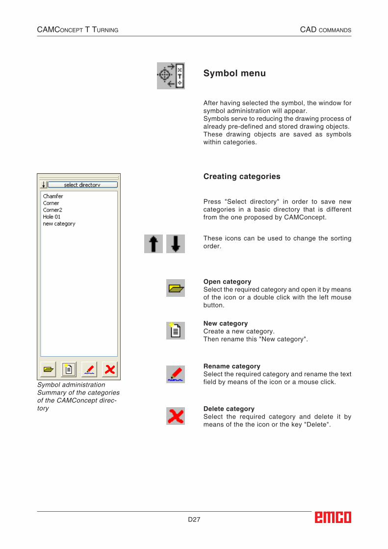
Symbol menu
After having selected the symbol, the window for symbol administration will appear.Symbols serve to reducing the drawing process of already pre-defined and stored drawing objects.These drawing objects are saved as symbols within categories.
Press "Select directory" in order to save new categories in a basic directory that is different from the one proposed by CAMConcept.
Open categorySelect the required category and open it by means of the icon or a double click with the left mouse button.
New categoryCreate a new category. Then rename this "New category".
Rename categorySelect the required category and rename the text field by means of the icon or a mouse click.
Delete categorySelect the required category and delete it by means of the the icon or the key "Delete".
Creating categories
Symbol administrationSummary of the categoriesof the CAMConcept direc-tory
CAMConCept t turning CAD CoMMAnDs
These icons can be used to change the sorting order.
##CAD:Symbolmenue##
D28
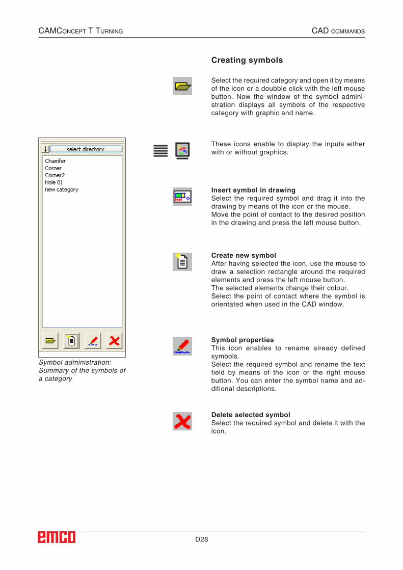
Insert symbol in drawingSelect the required symbol and drag it into the drawing by means of the icon or the mouse.Move the point of contact to the desired position in the drawing and press the left mouse button.
Create new symbolAfter having selected the icon, use the mouse to draw a selection rectangle around the required elements and press the left mouse button.The selected elements change their colour.Select the point of contact where the symbol is orientated when used in the CAD window.
Symbol propertiesThis icon enables to rename already defined symbols.Select the required symbol and rename the text field by means of the icon or the right mouse button. You can enter the symbol name and ad-ditional descriptions.
Symbol administration:Summary of the symbols ofa category
Select the required category and open it by means of the icon or a doubble click with the left mouse button. Now the window of the symbol admini-stration displays all symbols of the respective category with graphic and name.
These icons enable to display the inputs either with or without graphics.
Delete selected symbolSelect the required symbol and delete it with the icon.
Creating symbols
CAMConCept t turning CAD CoMMAnDs
##CAD:Symbole_erstellen##
D29
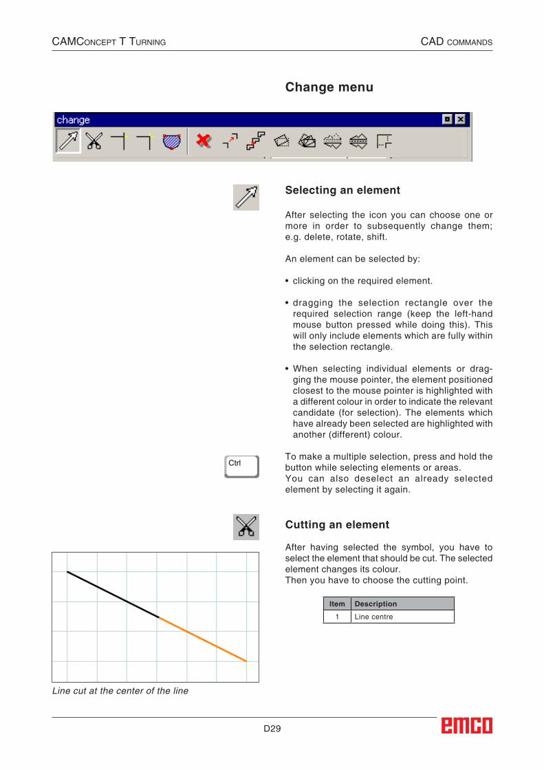
Cutting an element
After having selected the symbol, you have to select the element that should be cut. The selected element changes its colour.Then you have to choose the cutting point.
Line cut at the center of the line
CAMConCept t turning CAD CoMMAnDs
Change menu
Selecting an element
After selecting the icon you can choose one or more in order to subsequently change them; e.g. delete, rotate, shift.
An element can be selected by:
• clicking on the required element.
• dragging the selection rectangle over the required selection range (keep the left-hand mouse button pressed while doing this). This will only include elements which are fully within the selection rectangle.
• When selecting individual elements or drag-ging the mouse pointer, the element positioned closest to the mouse pointer is highlighted with a different colour in order to indicate the relevant candidate (for selection). The elements which have already been selected are highlighted with another (different) colour.
To make a multiple selection, press and hold the button while selecting elements or areas.You can also deselect an already selected element by selecting it again.
Item Description
1 Line centre
##CAD:AEnderungsmenue##
##CAD:Element_teilen##
##CAD:Modify_Selection##
Ctrl
D30
2 1 2 1
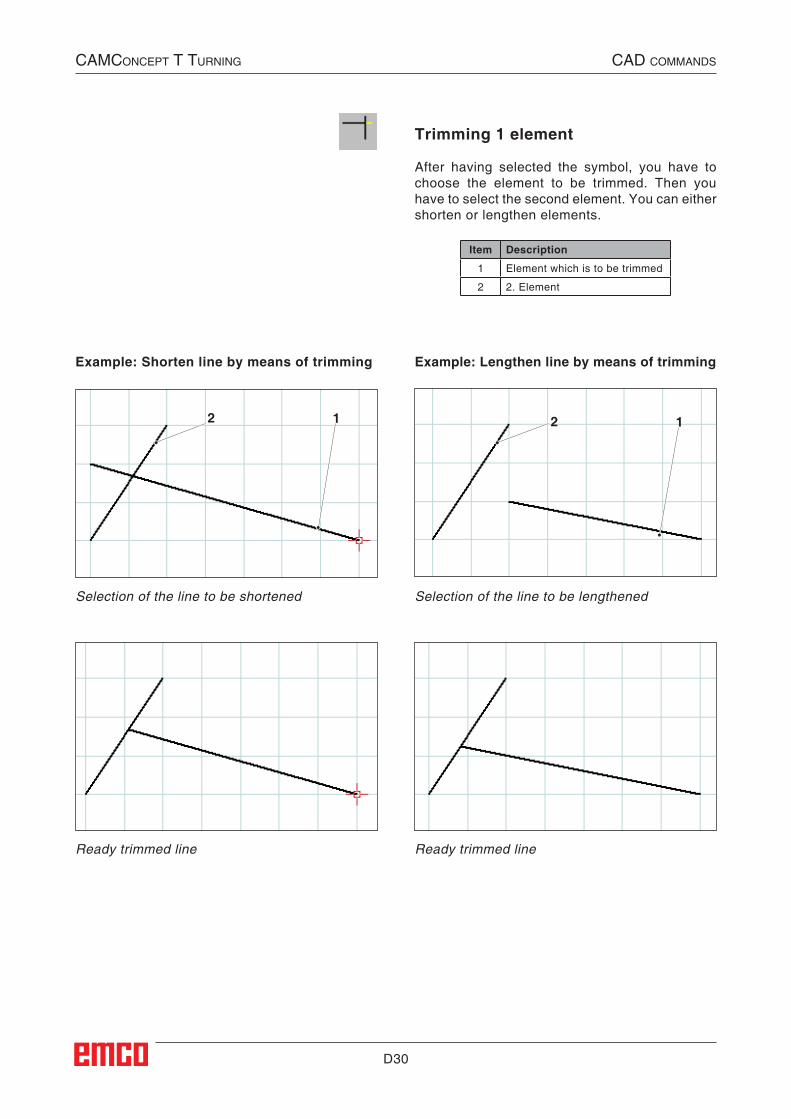
Trimming 1 element
After having selected the symbol, you have to choose the element to be trimmed. Then you have to select the second element. You can either shorten or lengthen elements.
Example: Shorten line by means of trimming Example: Lengthen line by means of trimming
Selection of the line to be shortened
Ready trimmed line
Selection of the line to be lengthened
Ready trimmed line
CAMConCept t turning CAD CoMMAnDs
Item Description
1 Element which is to be trimmed
2 2. Element
##CAD:1_Element_Trimmen##
D31
1b
3
4
2a
1a
1b
2b
2b
2a
1a
2a
1a
1b
2b
2a
1a
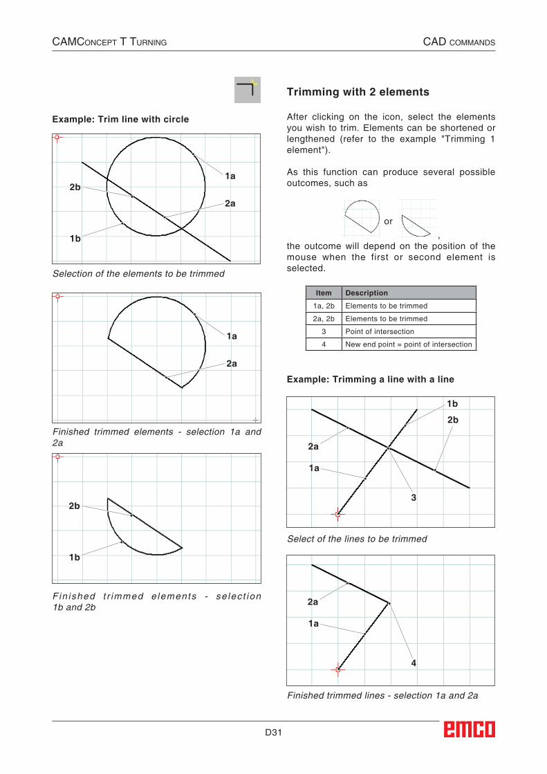
Example: Trim line with circle
CAMConCept t turning CAD CoMMAnDs
Trimming with 2 elements
After clicking on the icon, select the elements you wish to trim. Elements can be shortened or lengthened (refer to the example "Trimming 1 element").
As this function can produce several possible outcomes, such as
or
, the outcome will depend on the position of the mouse when the first or second element is selected.
Item Description
1a, 2b Elements to be trimmed
2a, 2b Elements to be trimmed
3 Point of intersection
4 New end point = point of intersection
Example: Trimming a line with a line
Select of the lines to be trimmed
Finished trimmed lines - selection 1a and 2a
Selection of the elements to be trimmed
Finished trimmed elements - selection 1a and 2a
Fin ished t r immed e lements - se lec t ion 1b and 2b
##CAD:Trimmen_mit_2_Elementen##
D32
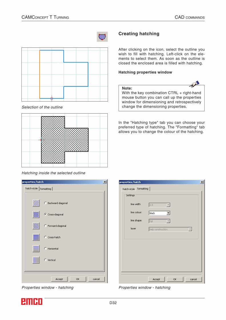
In the "Hatching type" tab you can choose your preferred type of hatching. The "Formatting" tab allows you to change the colour of the hatching.
CAMConCept t turning CAD CoMMAnDs
Creating hatching
After clicking on the icon, select the outline you wish to fill with hatching. Left-click on the ele-ments to select them. As soon as the outline is closed the enclosed area is filled with hatching.
Hatching properties window
Hatching inside the selected outline
Selection of the outline
Properties window - hatching Properties window - hatching
Note:With the key combination CTRL + right-hand mouse button you can call up the properties window for dimensioning and retrospectively change the dimensioning properties.
##CAD:Schaffur_erzeugen##
D33
1
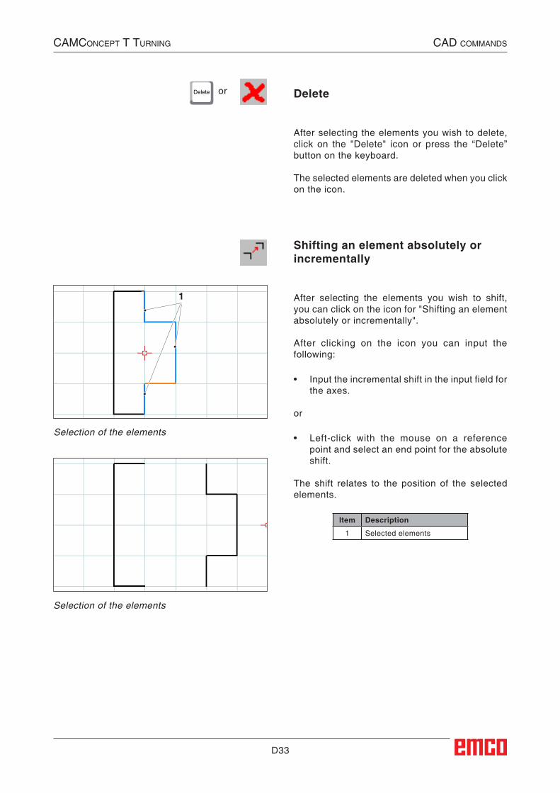
Delete or
CAMConCept t turning CAD CoMMAnDs
Shifting an element absolutely or incrementally
After selecting the elements you wish to shift, you can click on the icon for "Shifting an element absolutely or incrementally".
After clicking on the icon you can input the following:
• Input the incremental shift in the input field for the axes.
or
• Left-click with the mouse on a reference point and select an end point for the absolute shift.
The shift relates to the position of the selected elements.
Item Description
1 Selected elements
Selection of the elements
Selection of the elements
Delete
After selecting the elements you wish to delete, click on the "Delete" icon or press the “Delete” button on the keyboard.
The selected elements are deleted when you click on the icon.
##CAD:Element_Absolut_oder_Inkrementell_verschieben##
##CAD:Loeschen##
D34
1
CAMConCept t turning CAD CoMMAnDs
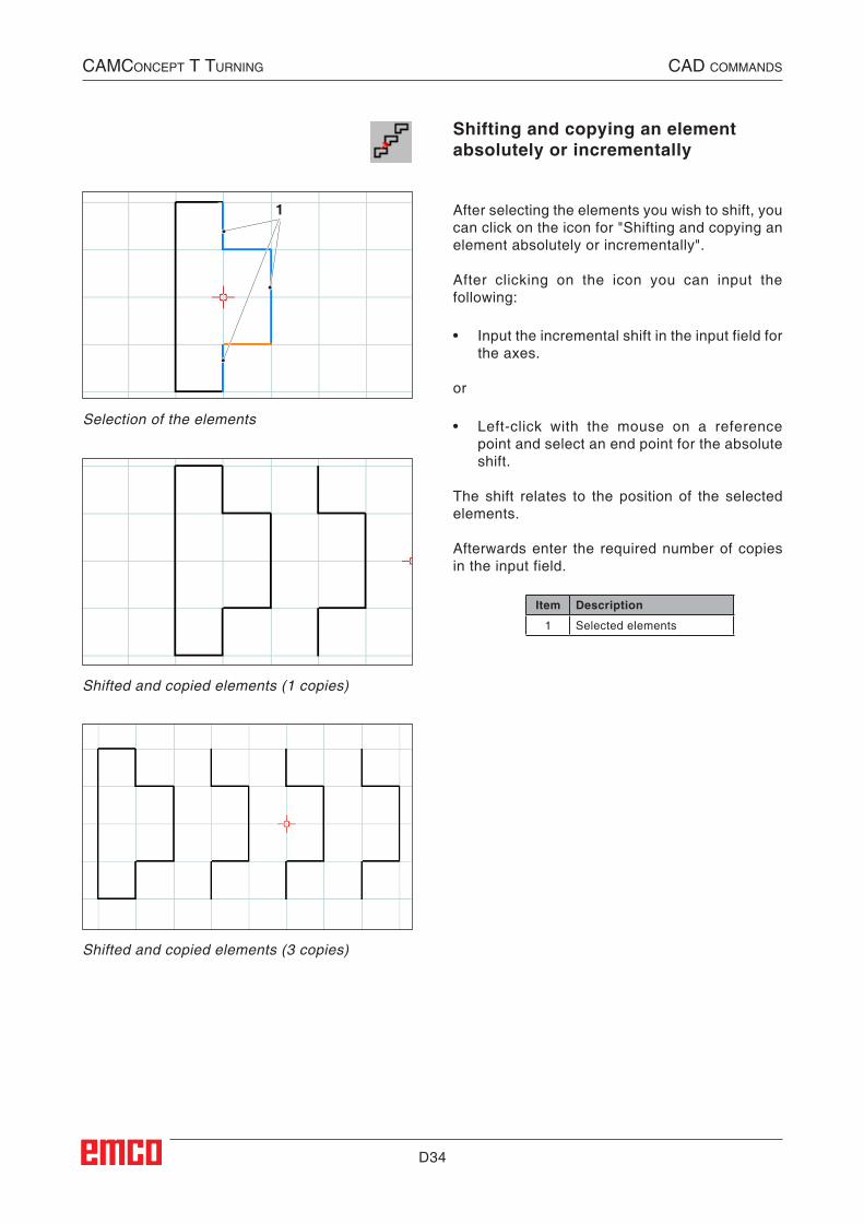
Shifting and copying an element absolutely or incrementally
After selecting the elements you wish to shift, you can click on the icon for "Shifting and copying an element absolutely or incrementally".
After clicking on the icon you can input the following:
• Input the incremental shift in the input field for the axes.
or
• Left-click with the mouse on a reference point and select an end point for the absolute shift.
The shift relates to the position of the selected elements.
Afterwards enter the required number of copies in the input field.
Item Description
1 Selected elements
Shifted and copied elements (1 copies)
Shifted and copied elements (3 copies)
Selection of the elements
##CAD:Element_Absolut_oder_Inkrementell_verschieben_und_kopieren##
D35
2
1
CAMConCept t turning CAD CoMMAnDs
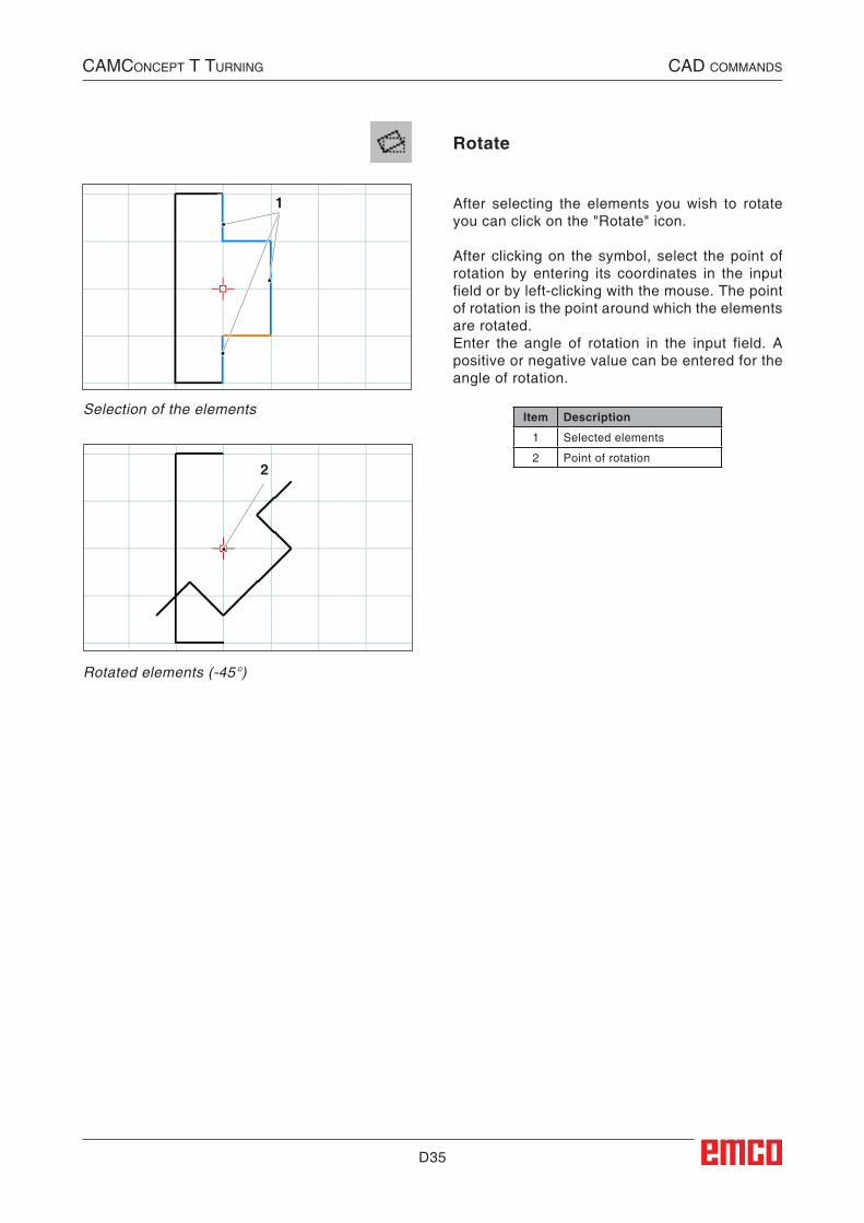
Rotate
After selecting the elements you wish to rotate you can click on the "Rotate" icon.
After clicking on the symbol, select the point of rotation by entering its coordinates in the input field or by left-clicking with the mouse. The point of rotation is the point around which the elements are rotated.Enter the angle of rotation in the input field. A positive or negative value can be entered for the angle of rotation.
Item Description
1 Selected elements
2 Point of rotation
Selection of the elements
Rotated elements (-45°)
##CAD:Rotieren##
D36
2
1
2
CAMConCept t turning CAD CoMMAnDs
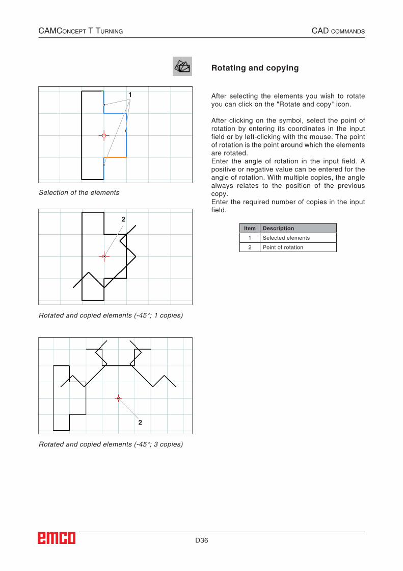
Rotating and copying
After selecting the elements you wish to rotate you can click on the "Rotate and copy" icon.
After clicking on the symbol, select the point of rotation by entering its coordinates in the input field or by left-clicking with the mouse. The point of rotation is the point around which the elements are rotated.Enter the angle of rotation in the input field. A positive or negative value can be entered for the angle of rotation. With multiple copies, the angle always relates to the position of the previous copy.Enter the required number of copies in the input field.
Item Description
1 Selected elements
2 Point of rotation
Selection of the elements
Rotated and copied elements (-45°; 1 copies)
Rotated and copied elements (-45°; 3 copies)
##CAD:Rotieren_und_Kopieren##
D37
1 2
3
CAMConCept t turning CAD CoMMAnDs
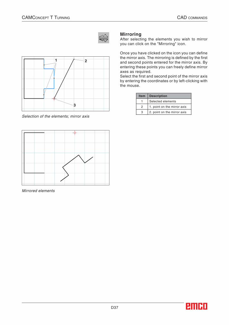
MirroringAfter selecting the elements you wish to mirror you can click on the "Mirroring" icon.
Once you have clicked on the icon you can define the mirror axis. The mirroring is defined by the first and second points entered for the mirror axis. By entering these points you can freely define mirror axes as required.Select the first and second point of the mirror axis by entering the coordinates or by left-clicking with the mouse.
Item Description
1 Selected elements
2 1. point on the mirror axis
3 2. point on the mirror axisSelection of the elements; mirror axis
Mirrored elements
##CAD:Spiegeln##
D38
12
3
4
5
CAMConCept t turning CAD CoMMAnDs
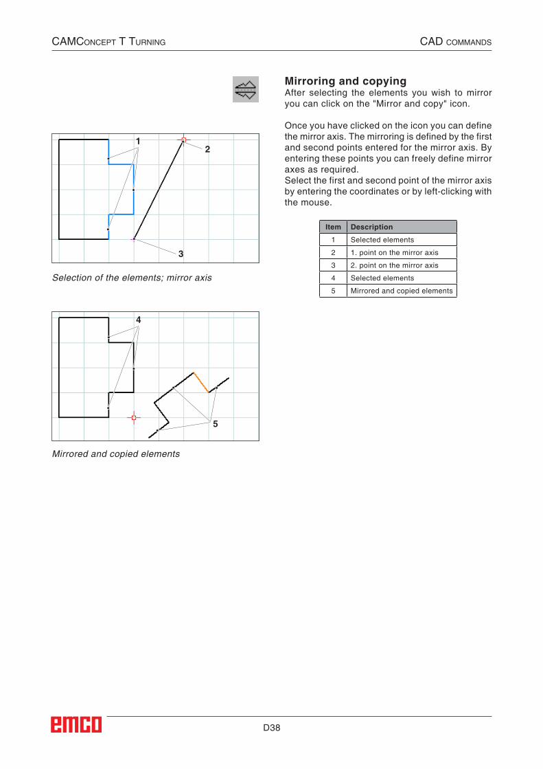
Mirroring and copyingAfter selecting the elements you wish to mirror you can click on the "Mirror and copy" icon.
Once you have clicked on the icon you can define the mirror axis. The mirroring is defined by the first and second points entered for the mirror axis. By entering these points you can freely define mirror axes as required.Select the first and second point of the mirror axis by entering the coordinates or by left-clicking with the mouse.
Item Description
1 Selected elements
2 1. point on the mirror axis
3 2. point on the mirror axis
4 Selected elements
5 Mirrored and copied elements
Selection of the elements; mirror axis
Mirrored and copied elements
##Spiegeln_und_Kopieren##
D39
1
2
1
2
CAMConCept t turning CAD CoMMAnDs
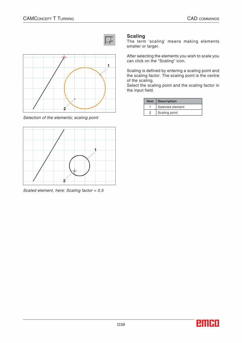
ScalingThe term 'scaling' means making elements smaller or larger.
After selecting the elements you wish to scale you can click on the "Scaling" icon.
Scaling is defined by entering a scaling point and the scaling factor. The scaling point is the centre of the scaling.Select the scaling point and the scaling factor in the input field.
Item Description
1 Selected element
2 Scaling point
Selection of the elements; scaling point
Scaled element, here: Scaling factor = 0.5
##CAD:Skalieren##

D40
CAMConCept t turning CAD CoMMAnDs
E1
E: CAM commands
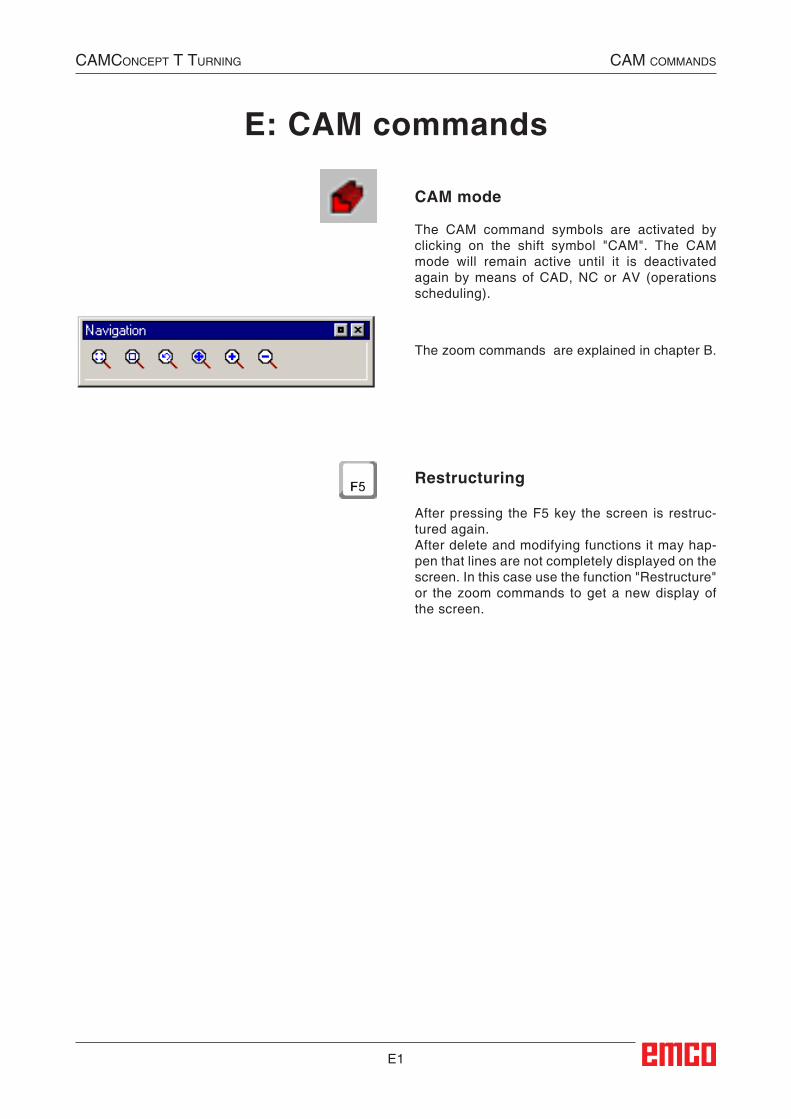
CAM mode
The CAM command symbols are activated by clicking on the shift symbol "CAM". The CAM mode will remain active until it is deactivated again by means of CAD, NC or AV (operations scheduling).
The zoom commands are explained in chapter B.
Restructuring
After pressing the F5 key the screen is restruc-tured again.After delete and modifying functions it may hap-pen that lines are not completely displayed on the screen. In this case use the function "Restructure" or the zoom commands to get a new display of the screen.
CAMConCept t turning CAM CoMMAnds
##Neuzeichnen##
E2
Machine
Settings
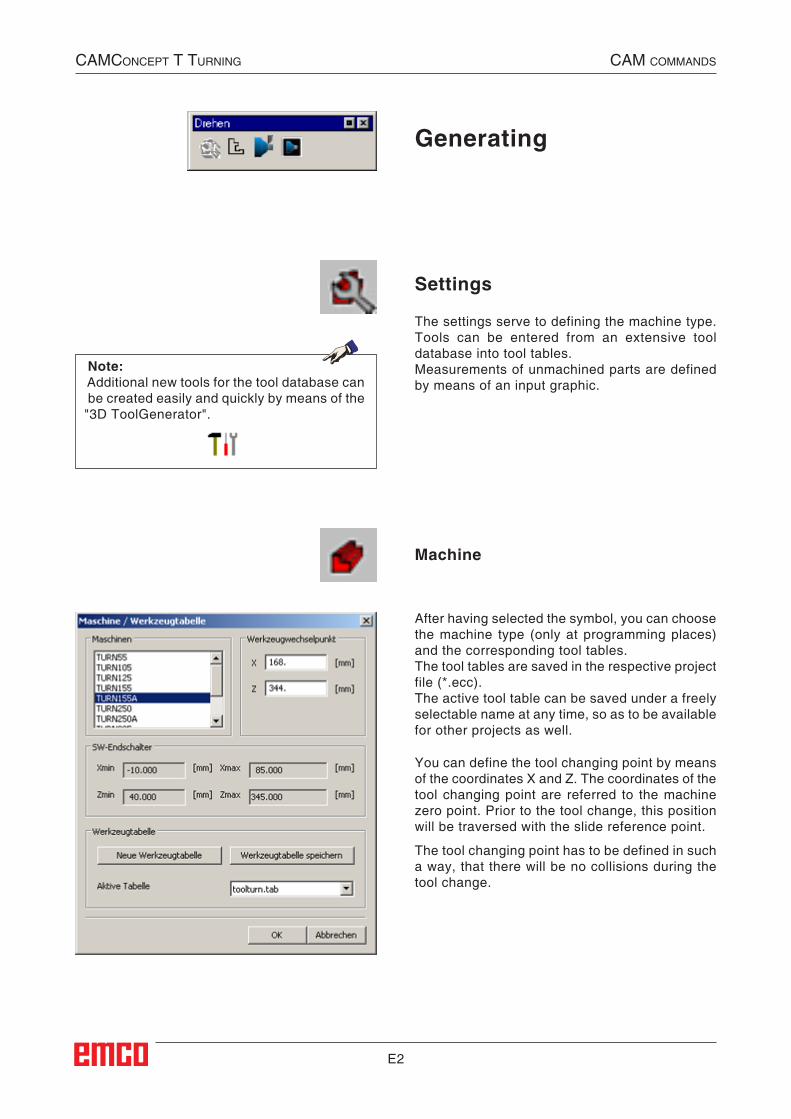
Generating
After having selected the symbol, you can choose the machine type (only at programming places) and the corresponding tool tables.The tool tables are saved in the respective project file (*.ecc).The active tool table can be saved under a freely selectable name at any time, so as to be available for other projects as well.
The settings serve to defining the machine type. Tools can be entered from an extensive tool database into tool tables.Measurements of unmachined parts are defined by means of an input graphic.
You can define the tool changing point by means of the coordinates X and Z. The coordinates of the tool changing point are referred to the machine zero point. Prior to the tool change, this position will be traversed with the slide reference point.
The tool changing point has to be defined in such a way, that there will be no collisions during the tool change.
Note:Additional new tools for the tool database can be created easily and quickly by means of the "3D ToolGenerator".
CAMConCept t turning CAM CoMMAnds
##CAM:Maschine##
##Einstellungen##
##CAM:Erzeugen_Anstellungen##
E3
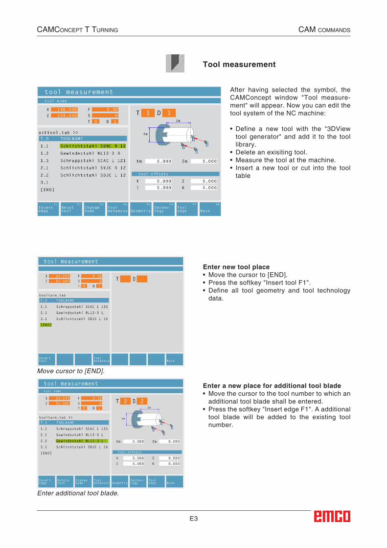
After having selected the symbol, the CAMConcept window "Tool measure-ment" will appear. Now you can edit the tool system of the NC machine:
• Define a new tool with the "3DView tool generator" and add it to the tool library.
• Delete an exisiting tool.• Measure the tool at the machine.• Insert a new tool or cut into the tool
table
Enter new tool place• Move the cursor to [END].• Press the softkey "Insert tool F1".• Define all tool geometry and tool technology
data.
Enter a new place for additional tool blade• Move the cursor to the tool number to which an
additional tool blade shall be entered.• Press the softkey "Insert edge F1". A additional
tool blade will be added to the existing tool number.
Move cursor to [END].
Enter additional tool blade.
CAMConCept t turning CAM CoMMAnds
Tool measurement##CAM:Werkzeugvermessung##
E4
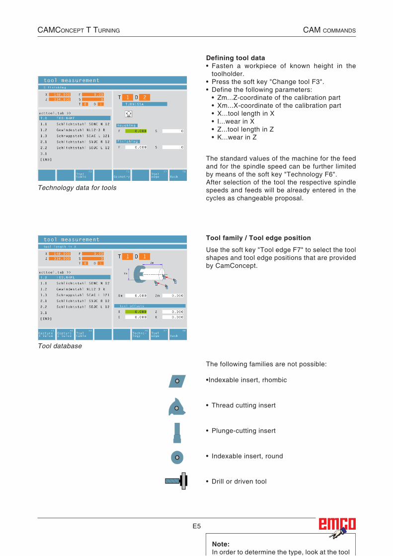
Tool database
Entering a tool from the tool database into the tool table• Press the soft key "Tool database F4".• Move the cursor keys to the tool you wish to
capture.• Press the soft key "Capture F8".• The required tool will be entered into the tool
table at the chosen position. A previous tool, if existing, will be replaced by
the new one.
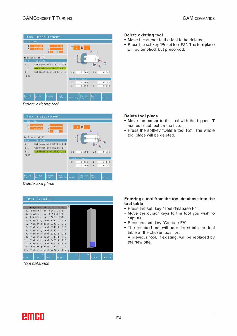
Delete existing tool• Move the cursor to the tool to be deleted.• Press the softkey "Reset tool F2". The tool place
will be emptied, but preserved.
Delete tool place• Move the cursor to the tool with the highest T
number (last tool on the list).• Press the softkey "Delete tool F2". The whole
tool place will be deleted.
Delete existing tool.
Delete tool place.
CAMConCept t turning CAM CoMMAnds
E5
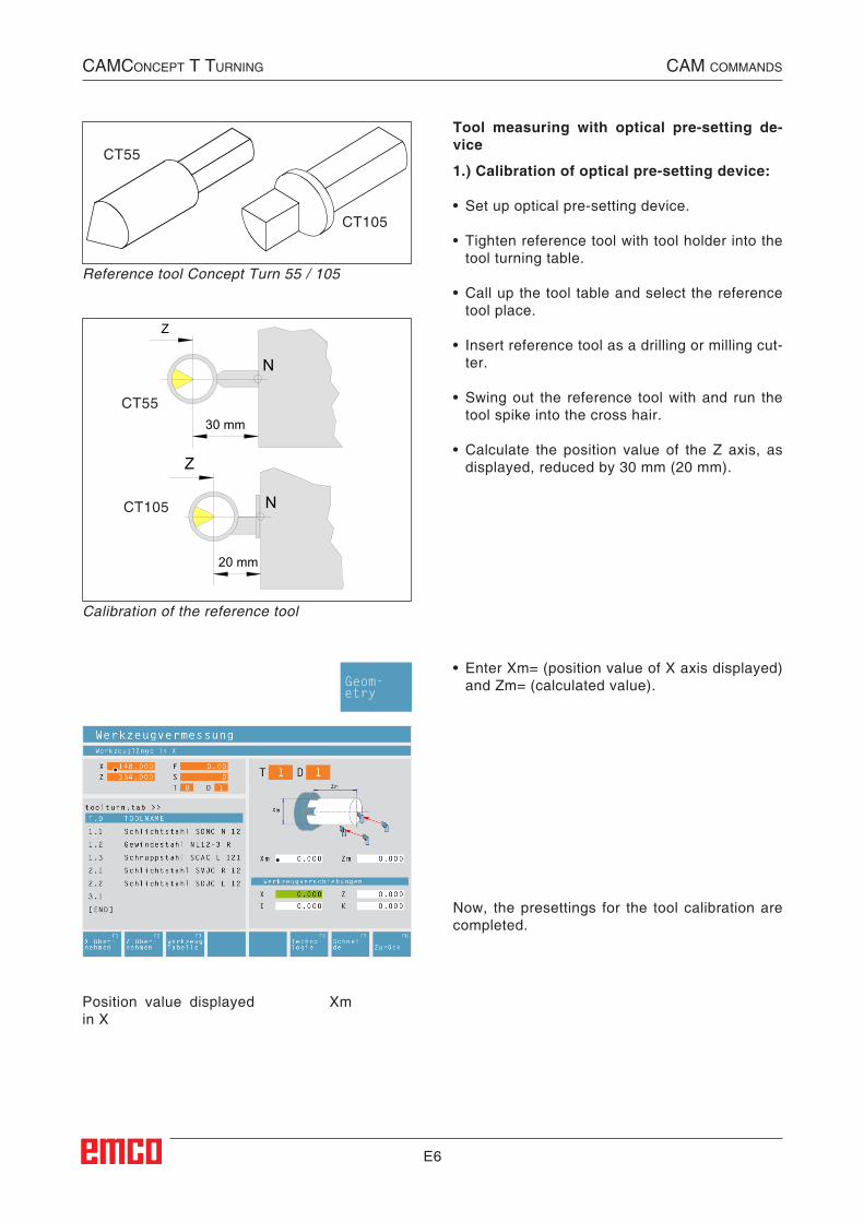
Tool family / Tool edge position
Use the soft key "Tool edge F7" to select the tool shapes and tool edge positions that are provided by CamConcept.
Defining tool data• Fasten a workpiece of known height in the
toolholder.• Press the soft key "Change tool F3".• Define the following parameters: • Zm...Z-coordinate of the calibration part • Xm...X-coordinate of the calibration part • X...tool length in X • I...wear in X • Z...tool length in Z • K...wear in Z
Technology data for tools
The standard values of the machine for the feed and for the spindle speed can be further limited by means of the soft key "Technology F6".After selection of the tool the respective spindle speeds and feeds will be already entered in the cycles as changeable proposal.
CAMConCept t turning CAM CoMMAnds
The following families are not possible:
•Indexable insert, rhombic
• Thread cutting insert
• Plunge-cutting insert
• Indexable insert, round
• Drill or driven tool
Note:In order to determine the type, look at the tool as it is clamped in the machine.In the case of machines in which the tool is above (behind) the centre of rotation, the values in parentheses must be used because of the reversal of the +X direction.
Tool database
E6
Now, the presettings for the tool calibration are completed.
Position value displayed in X
Xm
Reference tool Concept Turn 55 / 105
Calibration of the reference tool
CT55
CT105
Z
N
30 mm
Z
N
20 mm
CT55
CT105
Tool measuring with optical pre-setting de-vice
1.) Calibration of optical pre-setting device:
• Set up optical pre-setting device.
• Tighten reference tool with tool holder into the tool turning table.
• Call up the tool table and select the reference tool place.
• Insert reference tool as a drilling or milling cut-ter.
• Swing out the reference tool with and run the tool spike into the cross hair.
• Calculate the position value of the Z axis, as displayed, reduced by 30 mm (20 mm).
• Enter Xm= (position value of X axis displayed) and Zm= (calculated value).
CAMConCept t turning CAM CoMMAnds
Geom-etry
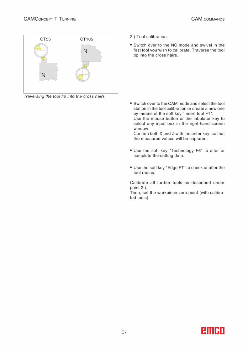
E7
2.) Tool calibration:
• Switch over to the NC mode and swivel in the first tool you wish to calibrate. Traverse the tool tip into the cross hairs.
Traversing the tool tip into the cross hairs
• Switch over to the CAM mode and select the tool station in the tool calibration or create a new one by means of the soft key "Insert tool F1".
Use the mouse button or the tabulator key to select any input box in the right-hand screen window.
Confirm both X and Z with the enter key, so that the measured values will be captured.
• Use the soft key "Technology F6" to alter or
complete the cutting data.
• Use the soft key "Edge F7" to check or alter the tool radius.
Calibrate all further tools as described under point 2.).Then, set the workpiece zero point (with calibra-ted tools).
N
N
CT55 CT105
CAMConCept t turning CAM CoMMAnds
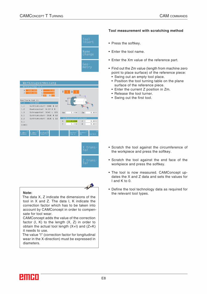
E8
CAMConCept t turning CAM CoMMAnds
Tool measurement with scratching method
• Press the softkey.
• Enter the tool name.
• Enter the Xm value of the reference part.
• Find out the Zm value (length from machine zero point to place surface) of the reference piece:
• Swing out an empty tool place.• Position the tool turning table on the plane
surface of the reference piece.• Enter the current Z position in Zm.• Release the tool turner.• Swing out the first tool.
Note:The data X, Z indicate the dimensions of the tool in X and Z. The data I, K indicate the correction factor which has to be taken into account by CAMConcept in order to compen-sate for tool wear.CAMConcept adds the value of the correction factor (I, K) to the length (X, Z) in order to obtain the actual tool length (X+I) and (Z+K) it needs to use.The value "I" (correction factor for longitudinal wear in the X-direction) must be expressed in diameters.
• Scratch the tool against the circumference of the workpiece and press the softkey.
• Scratch the tool against the end face of the workpiece and press the softkey.
• The tool is now measured. CAMConcept up-dates the X and Z data and sets the values for I and K to 0.
• Define the tool technology data as required for the relevant tool types.
Toolinsert
Namechange
Geo-metry
X trans-fer
Z trans-fer
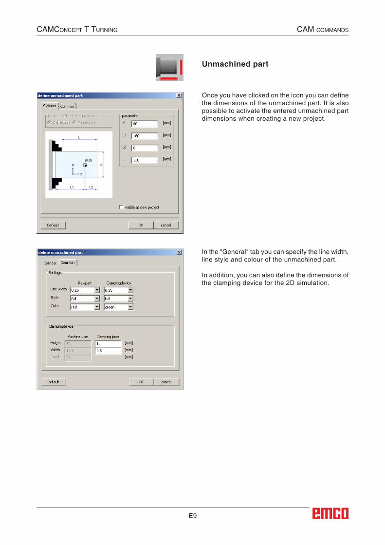
E9
CAMConCept t turning CAM CoMMAnds
Unmachined part
Once you have clicked on the icon you can define the dimensions of the unmachined part. It is also possible to activate the entered unmachined part dimensions when creating a new project.
In the "General" tab you can specify the line width, line style and colour of the unmachined part.
In addition, you can also define the dimensions of the clamping device for the 2D simulation.
##CAM:Rohteil##
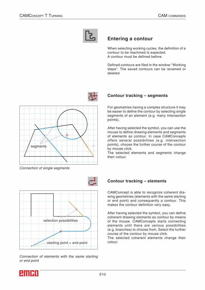
E10
Contour tracking – segments
For geometries having a complex structure it may be easier to define the contour by selecting single segments of an element (e.g. many intersection points).
After having selected the symbol, you can use the mouse to define drawing elements and segments of elements as contour. In case CAMConcepts offers several possibilities (e.g. intersection points), choose the further course of the contour by mouse click.The selected elements and segments change their colour.
When selecting working cycles, the definition of a contour to be machined is expected.A contour must be defined before.
Defined contours are filed in the window "Working steps". The saved contours can be renamed or deleted.
Contour tracking – elements
CAMConcept is able to recognize coherent dra-wing geometries (elements with the same starting or end point) and consequently a contour. This makes the contour definition very easy.
After having selected the symbol, you can define coherent drawing elements as contour by means of the mouse. CAMConcepts starts connecting elements until there are various possibilities (e.g. branches) to choose from. Select the further course of the contour by mouse click.The selected coherent elements change their colour.
Connection of elements with the same starting or end point
Connection of single segments
Entering a contour
segments
selection possibilities
starting point = end point
CAMConCept t turning CAM CoMMAnds
E11
Save contour
CAMConcept recognizes coherent contours and automatically saves them in the window "Working steps". After selection by means of the mouse, this sym-bol enables to define contours that have not been recognized automatically.
Cancel contour
With this symbol you can cancel already selected elements (elements with changed colour). The contour will not be saved.
Note:You can cancel one element each of already selected elements (elements with changed colour) by means of the right mouse button. The contour can always be saved.
Define new starting point
You can define a new starting point of a contour only when a contour has already been defined before.CAMConcept draws the current starting point of the contour.
After selection of the symbol you have to enter the new starting point of the contour.
CAMConCept t turning CAM CoMMAnds
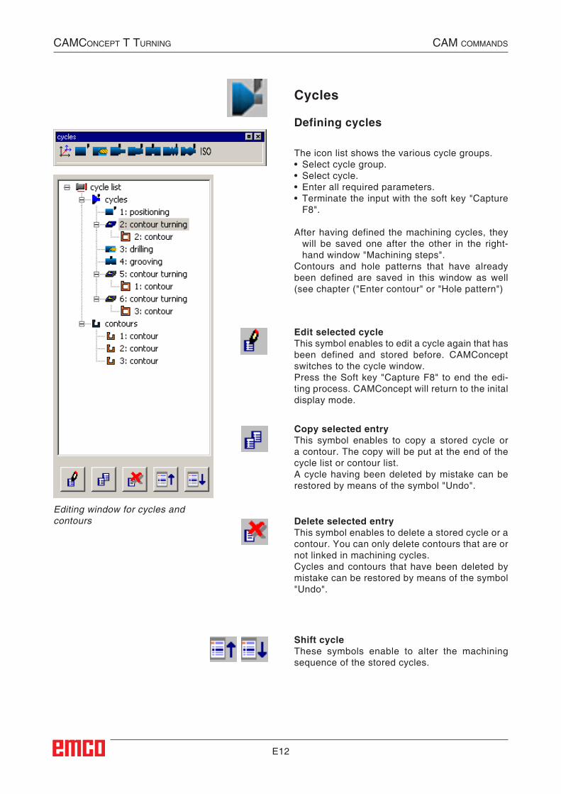
E12
Defining cycles
Cycles
The icon list shows the various cycle groups.• Select cycle group.• Select cycle.• Enter all required parameters.• Terminate the input with the soft key "Capture
F8".
After having defined the machining cycles, they will be saved one after the other in the right-hand window "Machining steps".
Contours and hole patterns that have already been defined are saved in this window as well (see chapter ("Enter contour" or "Hole pattern")
Edit selected cycleThis symbol enables to edit a cycle again that has been defined and stored before. CAMConcept switches to the cycle window.Press the Soft key "Capture F8" to end the edi-ting process. CAMConcept will return to the inital display mode.
Shift cycleThese symbols enable to alter the machining sequence of the stored cycles.
Copy selected entryThis symbol enables to copy a stored cycle or a contour. The copy will be put at the end of the cycle list or contour list.A cycle having been deleted by mistake can be restored by means of the symbol "Undo".
Delete selected entryThis symbol enables to delete a stored cycle or a contour. You can only delete contours that are or not linked in machining cycles.Cycles and contours that have been deleted by mistake can be restored by means of the symbol "Undo".
CAMConCept t turning CAM CoMMAnds
Editing window for cycles and contours
##CAM:Zyklen##
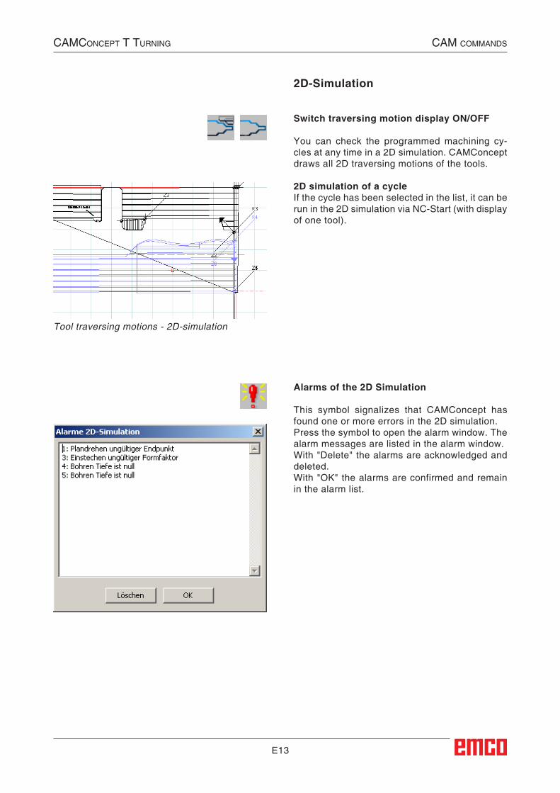
E13
Alarms of the 2D Simulation
This symbol signalizes that CAMConcept has found one or more errors in the 2D simulation.Press the symbol to open the alarm window. The alarm messages are listed in the alarm window.With "Delete" the alarms are acknowledged and deleted.With "OK" the alarms are confirmed and remain in the alarm list.
2D-Simulation
CAMConCept t turning CAM CoMMAnds
##Switch_2D_simulation_ON/OFF##Switch traversing motion display ON/OFF
You can check the programmed machining cy-cles at any time in a 2D simulation. CAM Concept draws all 2D traversing motions of the tools.
2D simulation of a cycleIf the cycle has been selected in the list, it can be run in the 2D simulation via NC-Start (with display of one tool).
Tool traversing motions - 2D-simulation
##Alarme_der_2D-Simulation##
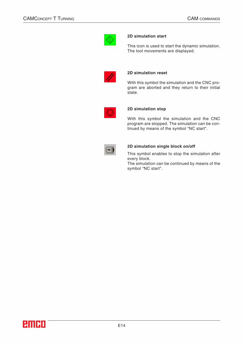
E14
2D simulation reset
With this symbol the simulation and the CNC pro-gram are aborted and they return to their initial state.
2D simulation stop
With this symbol the simulation and the CNC program are stopped. The simulation can be con-tinued by means of the symbol "NC start".
2D simulation single block on/off
This symbol enables to stop the simulation after every block.The simulation can be continued by means of the symbol "NC start".
CAMConCept t turning CAM CoMMAnds
2D simulation start
This icon is used to start the dynamic simulation. The tool movements are displayed.
##2D-Simulation_Einzelsatz_ein/aus##
##2D-Simulation_Stop##
##2D-Simulation_Reset##
##2D-Simulation_Start##
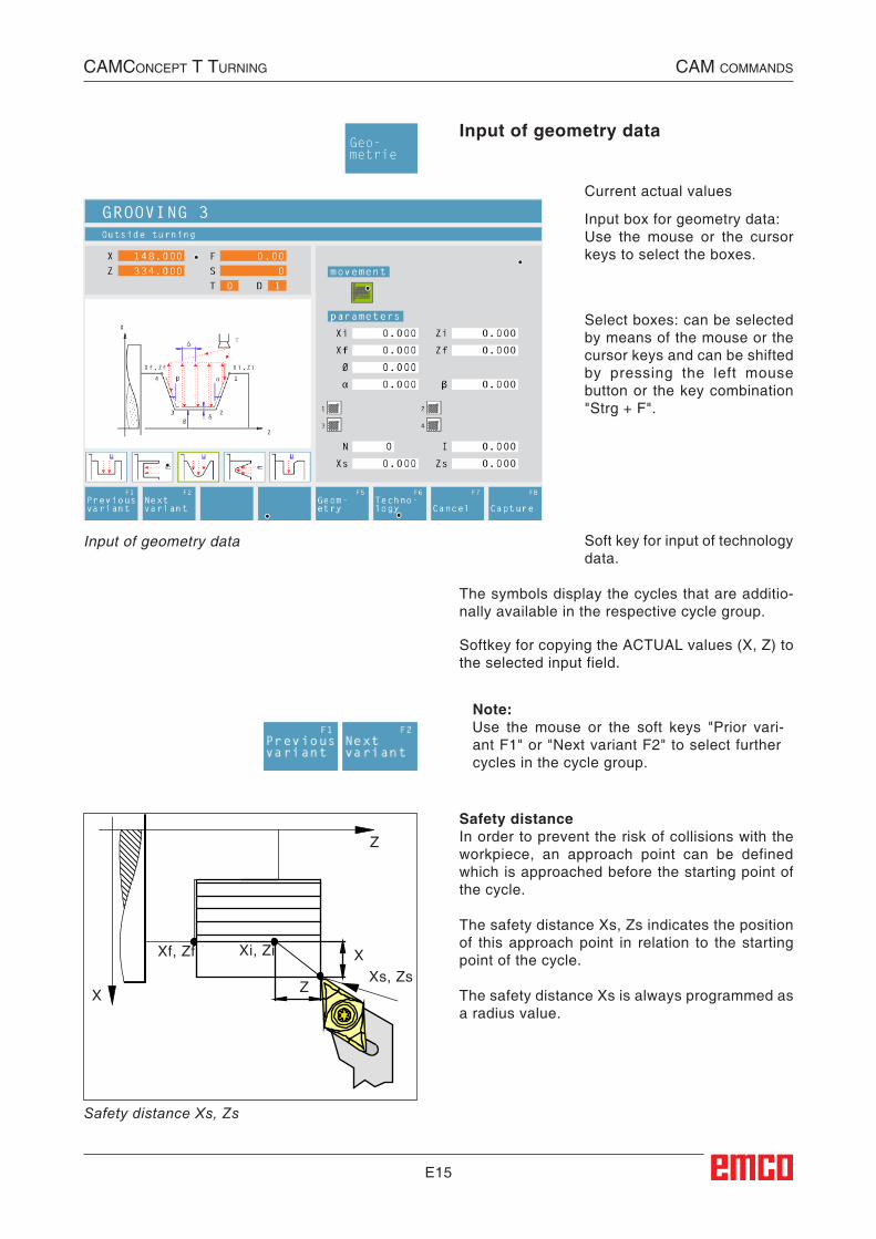
E15
Input of geometry data
Current actual values
The symbols display the cycles that are additio-nally available in the respective cycle group.
Input box for geometry data: Use the mouse or the cursor keys to select the boxes.
Select boxes: can be selected by means of the mouse or the cursor keys and can be shifted by pressing the left mouse button or the key combination "Strg + F".
Soft key for input of technology data.
Input of geometry data
Z
X
X
Z
Xi, ZiXf, Zf
Xs, Zs
Note:Use the mouse or the soft keys "Prior vari-ant F1" or "Next variant F2" to select further cycles in the cycle group.
Geo-metrie
CAMConCept t turning CAM CoMMAnds
Safety distanceIn order to prevent the risk of collisions with the workpiece, an approach point can be defined which is approached before the starting point of the cycle.
The safety distance Xs, Zs indicates the position of this approach point in relation to the starting point of the cycle.
The safety distance Xs is always programmed as a radius value.
Safety distance Xs, Zs
Softkey for copying the ACTUAL values (X, Z) to the selected input field.
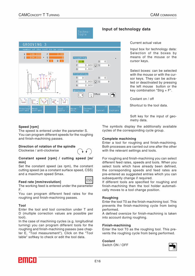
E16
Input of technology data
The symbols display the additionally available cycles of the corresponding cycle group.
Current actual value
Select boxes: can be selected with the mouse or with the cur-sor keys. They can be activa-ted or deactivated by pressing the left mouse button or the key combination "Strg + F".
Soft key for the input of geo-metry data.
Coolant on / off
Input box for technology data: Selection of the boxes by means of the mouse or the cursor keys.
Techno-logie
CSS
CAMConCept t turning CAM CoMMAnds
Speed [rpm]The speed is entered under the parameter S.You can program different speeds for the roughing and finish-machining passes.
Direction of rotation of the spindleClockwise / anti-clockwise
Constant speed [rpm] / cutting speed [m/min]Set the constant speed (as rpm), the constant cutting speed (as a constant surface speed, CSS) and a maximum speed Smax.
Feed rate [mm/revolution]The working feed is entered under the parameter F.You can program different feed rates for the roughing and finish-machining passes.
ToolEnter the tool and tool correction under T and D (multiple correction values are possible per tool).In the case of machining cycles (e.g. longitudinal turning) you can program different tools for the roughing and finish-machining passes (see chap-ter E, "Tool measurement"). Click on the "Tool table" softkey to check or edit the tool data.
Complete machiningEnter a tool for roughing and finish-machining. Both processes are carried out one after the other with the relevant settings and tools.
For roughing and finish-machining you can select different feed rates, speeds and tools. When you select tools which have already been defined, the corresponding speeds and feed rates are pre-entered as suggested entries which you can subsequently change if required.If different tools are specified for roughing and finish-machining then the tool holder automati-cally moves to a tool change position.
RoughingEnter the tool T0 as the finish-machining tool. This prevents the finish-machining cycle from being performed.A defined oversize for finish-machining is taken into account during roughing.
Finish-machiningEnter the tool T0 as the roughing tool. This pre-vents the roughing cycle from being performed.
CoolantSwitch ON / OFF
Shortcut to the tool data.
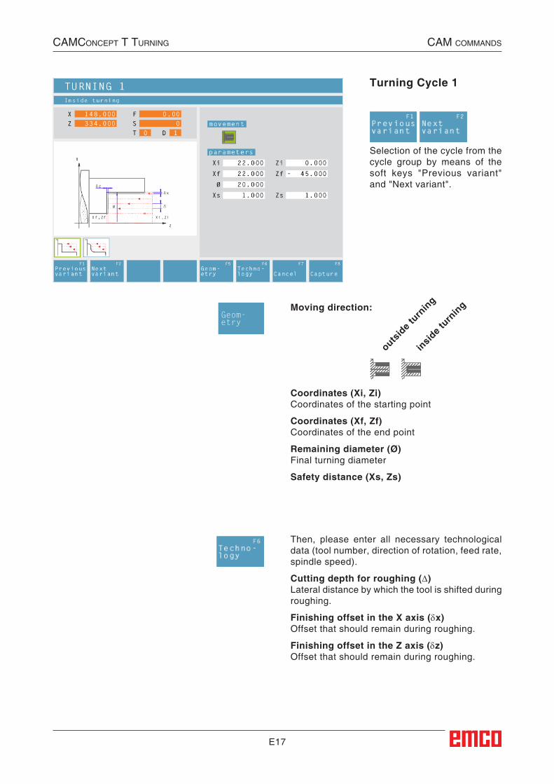
E17
Turning Cycle 1
Coordinates (Xi, Zi)Coordinates of the starting point
Coordinates (Xf, Zf)Coordinates of the end point
Remaining diameter (Ø)Final turning diameter
Safety distance (Xs, Zs)
Selection of the cycle from the cycle group by means of the soft keys "Previous variant" and "Next variant".
Then, please enter all necessary technological data (tool number, direction of rotation, feed rate, spindle speed).
Cutting depth for roughing (∆)Lateral distance by which the tool is shifted during roughing.
Finishing offset in the X axis (δx)Offset that should remain during roughing.
Finishing offset in the Z axis (δz)Offset that should remain during roughing.
Moving direction:
outsid
e turn
ing
insid
e turn
ing
Geom-etry
CAMConCept t turning CAM CoMMAnds
##CAM:Laengsdrehen_1##
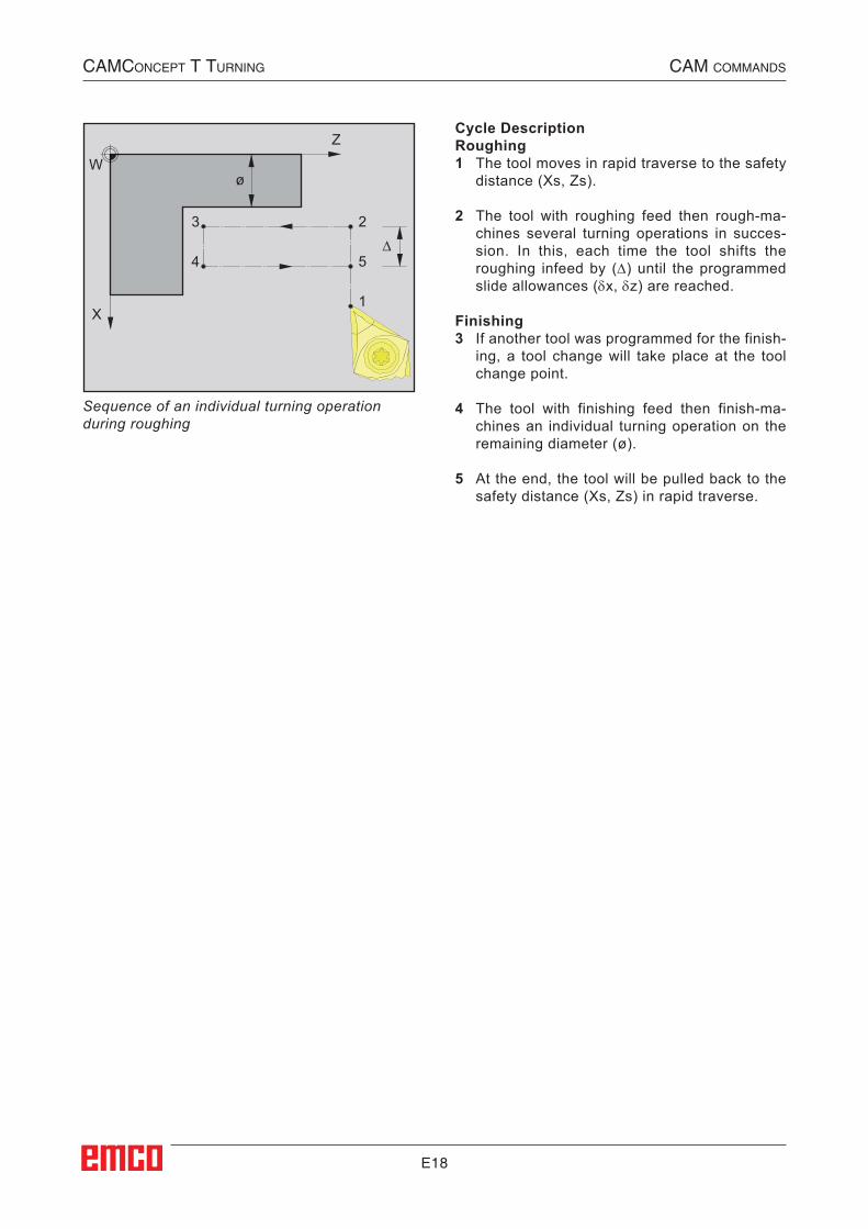
E18
Z
X1
2
4
3
5
W
∆
ø
Cycle DescriptionRoughing1 The tool moves in rapid traverse to the safety
distance (Xs, Zs).
2 The tool with roughing feed then rough-ma-chines several turning operations in succes-sion. In this, each time the tool shifts the roughing infeed by (∆) until the programmed slide allowances (δx, δz) are reached.
Finishing3 If another tool was programmed for the finish-
ing, a tool change will take place at the tool change point.
4 The tool with finishing feed then finish-ma-chines an individual turning operation on the remaining diameter (ø).
5 At the end, the tool will be pulled back to the safety distance (Xs, Zs) in rapid traverse.
Sequence of an individual turning operation during roughing
CAMConCept t turning CAM CoMMAnds
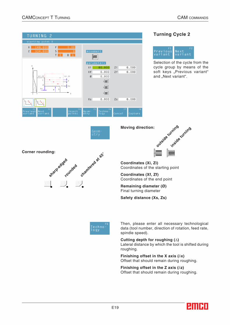
E19
Turning Cycle 2
Coordinates (Xi, Zi)Coordinates of the starting point
Coordinates (Xf, Zf)Coordinates of the end point
Remaining diameter (Ø)Final turning diameter
Safety distance (Xs, Zs)
Selection of the cycle from the cycle group by means of the soft keys „Previous variant“ and „Next variant“.
Then, please enter all necessary technological data (tool number, direction of rotation, feed rate, spindle speed).
Cutting depth for roughing (∆)Lateral distance by which the tool is shifted during roughing.
Finishing offset in the X axis (δx)Offset that should remain during roughing.
Finishing offset in the Z axis (δz)Offset that should remain during roughing.
Moving direction:
outsid
e turn
ing
insid
e turn
ing
Corner rounding:
shar
p-edged
rounded
cham
fere
d at 45
°
Geom-etry
CAMConCept t turning CAM CoMMAnds
##CAM:Laengsdrehen_2##

E20
Z
X1
2
4
3
5
W
∆
ø
Cycle DescriptionRoughing1 The tool moves in rapid traverse to the safety
distance (Xs, Zs).
2 The tool with roughing feed then rough-ma-chines several turning operations in succes-sion. In this, each time the tool shifts the roughing infeed by (∆) until the programmed slide allowances (δx, δz) are reached.
Finishing3 If another tool was programmed for the finishing,
a tool change will take place at the tool change point.
4 The tool with finishing feed then finish-ma-chines an individual turning operation on the remaining diameter (ø).
5 At the end, the tool will be pulled back to the safety distance (Xs, Zs) in rapid traverse.
Sequence of an individual turning operation during roughing
CAMConCept t turning CAM CoMMAnds
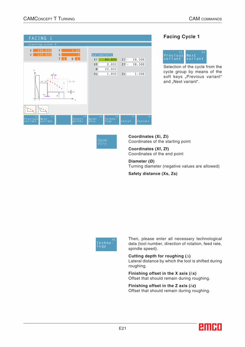
E21
Facing Cycle 1
Coordinates (Xi, Zi)Coordinates of the starting point
Coordinates (Xf, Zf)Coordinates of the end point
Diameter (Ø)Turning diameter (negative values are allowed)
Safety distance (Xs, Zs)
Selection of the cycle from the cycle group by means of the soft keys „Previous variant“ and „Next variant“.
Then, please enter all necessary technological data (tool number, direction of rotation, feed rate, spindle speed).
Cutting depth for roughing (∆)Lateral distance by which the tool is shifted during roughing.
Finishing offset in the X axis (δx)Offset that should remain during roughing.
Finishing offset in the Z axis (δz)Offset that should remain during roughing.
Geom-etry
CAMConCept t turning CAM CoMMAnds
##CAM:Plandrehen_1##

E22
Z
X
2
3 4
1
5
Wø
∆
Cycle DescriptionRoughing1 The tool moves in rapid traverse to the safety
distance (Xs, Zs).
2 The tool with roughing feed then rough-ma-chines several facing operations in succes-sion. In this, each time the tool shifts the roughing infeed by (∆) until the programmed slide allowances (δx, δz) are reached.
Finishing3 If another tool was programmed for the finish-
ing, a tool change will take place at the tool change point.
4 The tool with finishing feed then finish-ma-chines an individual facing operation on the remaining diameter (ø).
5 At the end, the tool will be pulled back to the safety distance (Xs, Zs) in rapid traverse.
Sequence of an individual facing operation during roughing
CAMConCept t turning CAM CoMMAnds
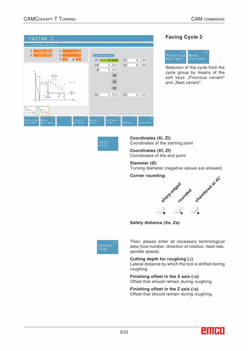
E23
Facing Cycle 2
Coordinates (Xi, Zi)Coordinates of the starting point
Coordinates (Xf, Zf)Coordinates of the end point
Diameter (Ø)Turning diameter (negative values are allowed)
Corner rounding:
Selection of the cycle from the cycle group by means of the soft keys „Previous variant“ and „Next variant“.
Then, please enter all necessary technological data (tool number, direction of rotation, feed rate, spindle speed).
Cutting depth for roughing (∆)Lateral distance by which the tool is shifted during roughing.
Finishing offset in the X axis (δx)Offset that should remain during roughing.
Finishing offset in the Z axis (δz)Offset that should remain during roughing.
shar
p-edged
rounded
cham
fere
d at 45
°
Safety distance (Xs, Zs)
Geom-etry
CAMConCept t turning CAM CoMMAnds
##CAM:Plandrehen_2##
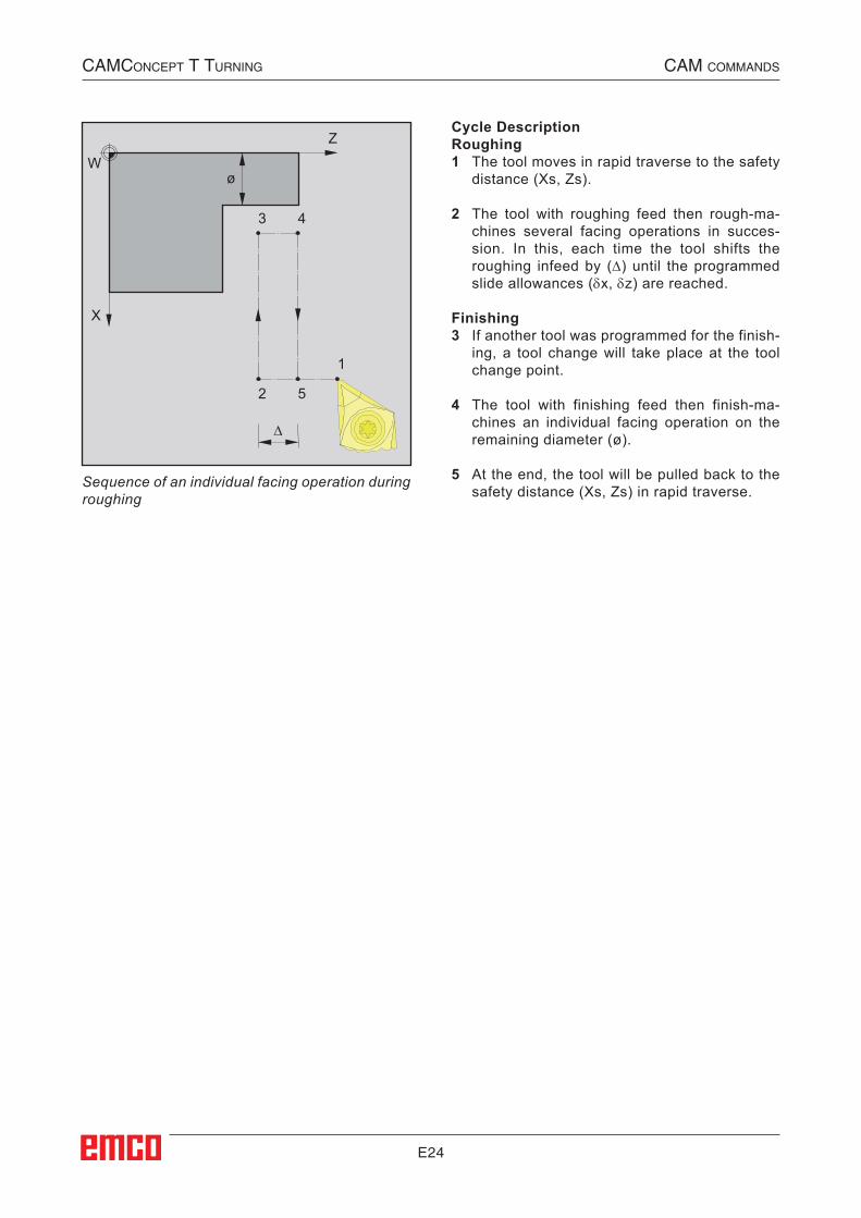
E24
Z
X
2
3 4
1
5
Wø
∆
Cycle DescriptionRoughing1 The tool moves in rapid traverse to the safety
distance (Xs, Zs).
2 The tool with roughing feed then rough-ma-chines several facing operations in succes-sion. In this, each time the tool shifts the roughing infeed by (∆) until the programmed slide allowances (δx, δz) are reached.
Finishing3 If another tool was programmed for the finish-
ing, a tool change will take place at the tool change point.
4 The tool with finishing feed then finish-ma-chines an individual facing operation on the remaining diameter (ø).
5 At the end, the tool will be pulled back to the safety distance (Xs, Zs) in rapid traverse.
Sequence of an individual facing operation during roughing
CAMConCept t turning CAM CoMMAnds
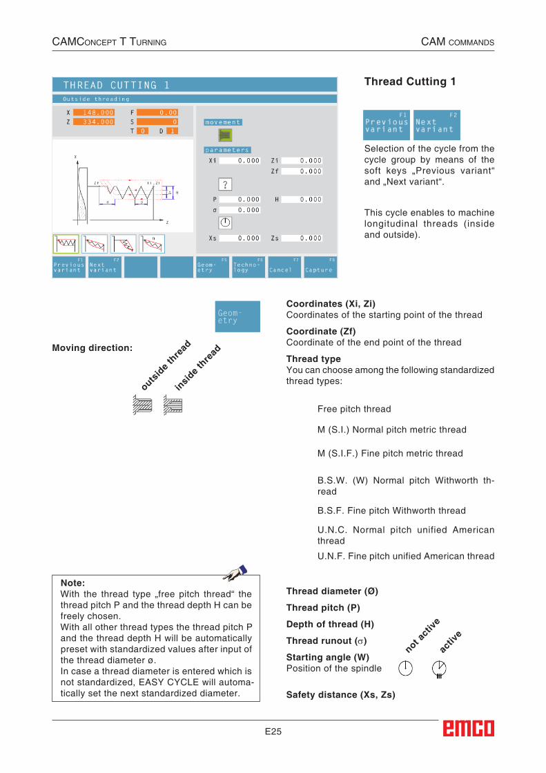
E25
Thread Cutting 1
Selection of the cycle from the cycle group by means of the soft keys „Previous variant“ and „Next variant“.
U.N.F. Fine pitch unified American thread
U.N.C. Normal pitch unified American thread
B.S.F. Fine pitch Withworth thread
B.S.W. (W) Normal pitch Withworth th-read
M (S.I.F.) Fine pitch metric thread
M (S.I.) Normal pitch metric thread
Free pitch thread
Thread diameter (Ø)
Thread pitch (P)
Depth of thread (H)
Thread runout (σ)
Starting angle (W)Position of the spindle
Coordinates (Xi, Zi)Coordinates of the starting point of the thread
Coordinate (Zf)Coordinate of the end point of the thread
Thread typeYou can choose among the following standardized thread types:
Moving direction:
outsid
e thre
ad
insid
e thre
ad
Safety distance (Xs, Zs)
not act
ive
activ
e
This cycle enables to machine longitudinal threads (inside and outside).
Note:With the thread type „free pitch thread“ the thread pitch P and the thread depth H can be freely chosen.With all other thread types the thread pitch P and the thread depth H will be automatically preset with standardized values after input of the thread diameter ø.In case a thread diameter is entered which is not standardized, EASY CYCLE will automa-tically set the next standardized diameter.
Geom-etry
CAMConCept t turning CAM CoMMAnds
##CAM:Gewindeschneiden201##
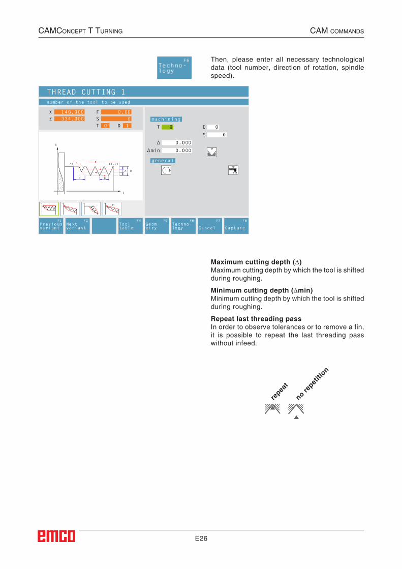
E26
Then, please enter all necessary technological data (tool number, direction of rotation, spindle speed).
Maximum cutting depth (∆)Maximum cutting depth by which the tool is shifted during roughing.
Minimum cutting depth (∆min)Minimum cutting depth by which the tool is shifted during roughing.
Repeat last threading passIn order to observe tolerances or to remove a fin, it is possible to repeat the last threading pass without infeed.
repea
t
no repet
ition
CAMConCept t turning CAM CoMMAnds

E27
Cycle Description1 According to the spindle's chosen direction of
rotation, a right or left thread will be turned.
2 The tool moves in rapid traverse to the safety distance (Xs, Zs).
3 The thread will be cut in several radial groov-ing operations until the thread depth (H) is reached. The infeed (∆) of the individual op-erations depends on which operation it is (∆, ∆√2, ∆√3, ∆√4, ...). If a decreasing infeed is lower than the minimum infeed (∆min), at least (∆min) will be fed in.
4 If selected - the tool repeats the last threading operation.
5 At the end, the tool will be pulled back to the safety distance (Xs, Zs) in rapid traverse.
CAMConCept t turning CAM CoMMAnds
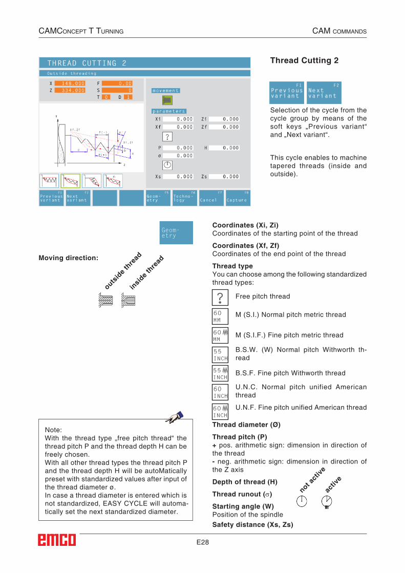
E28
Thread Cutting 2
Selection of the cycle from the cycle group by means of the soft keys „Previous variant“ and „Next variant“.
U.N.F. Fine pitch unified American thread
U.N.C. Normal pitch unified American thread
B.S.F. Fine pitch Withworth thread
B.S.W. (W) Normal pitch Withworth th-read
M (S.I.F.) Fine pitch metric thread
M (S.I.) Normal pitch metric thread
Free pitch thread
Thread diameter (Ø)
Thread pitch (P)+ pos. arithmetic sign: dimension in direction of the thread- neg. arithmetic sign: dimension in direction of the Z axis
Depth of thread (H)
Thread runout (σ)
Starting angle (W)Position of the spindle
Coordinates (Xi, Zi)Coordinates of the starting point of the thread
Coordinates (Xf, Zf)Coordinates of the end point of the thread
Thread typeYou can choose among the following standardized thread types:
Moving direction:
outsid
e thre
ad
insid
e thre
ad
Safety distance (Xs, Zs)
not act
ive
activ
e
This cycle enables to machine tapered threads (inside and outside).
Note:With the thread type „free pitch thread“ the thread pitch P and the thread depth H can be freely chosen.With all other thread types the thread pitch P and the thread depth H will be autoMatically preset with standardized values after input of the thread diameter ø.In case a thread diameter is entered which is not standardized, EASY CYCLE will automa-tically set the next standardized diameter.
Geom-etry
CAMConCept t turning CAM CoMMAnds
##CAM:Gewindeschneiden202##
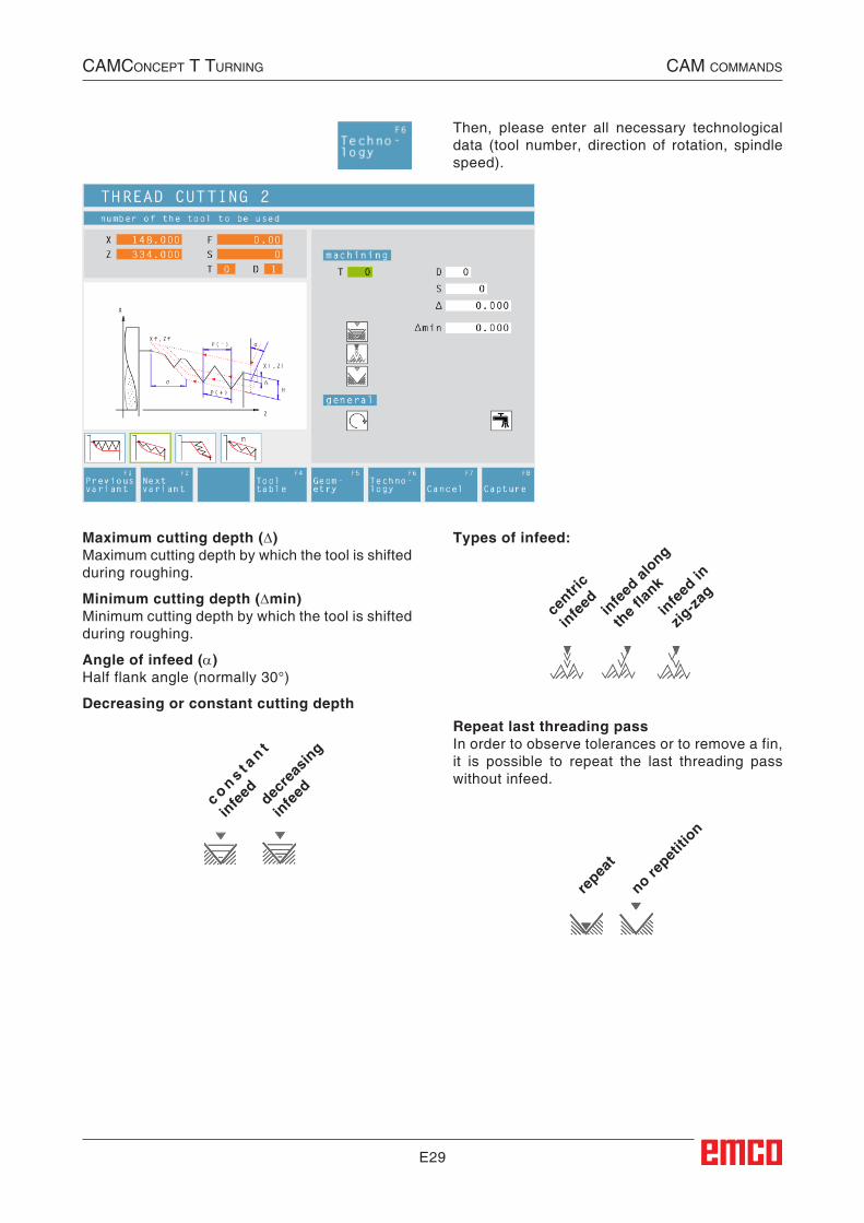
E29
Then, please enter all necessary technological data (tool number, direction of rotation, spindle speed).
Maximum cutting depth (∆)Maximum cutting depth by which the tool is shifted during roughing.
Minimum cutting depth (∆min)Minimum cutting depth by which the tool is shifted during roughing.
Angle of infeed (α)Half flank angle (normally 30°)
Decreasing or constant cutting depth
repea
t
no repet
ition
c o n s t an t
infe
ed decre
asin
g
infe
ed
Types of infeed:
centri
c
infe
ed infe
ed al
ong
the f
lank
infe
ed in
zig-za
g
Repeat last threading passIn order to observe tolerances or to remove a fin, it is possible to repeat the last threading pass without infeed.
CAMConCept t turning CAM CoMMAnds

E30
Cycle Description1 According to the spindle's chosen direction of
rotation, a right or left thread will be turned.
2 The tool moves in rapid traverse to the safety distance (Xs, Zs).
3 The thread will be cut in several operations until the thread depth (H) is reached.
The icon-selected infeed is carried out: • at a constant infeed each time of (∆),
• at an infeed decreasing by (∆, ∆√2, ∆√3, ∆√4, ...). If a decreasing infeed is lower than the minimum infeed (∆min), at least (∆min) will be fed in.
The icon-selected infeed type will be taken into account.
4 If selected - the tool repeats the last threading operation.
5 At the end, the tool will be pulled back to the safety distance (Xs, Zs) in rapid traverse.
CAMConCept t turning CAM CoMMAnds
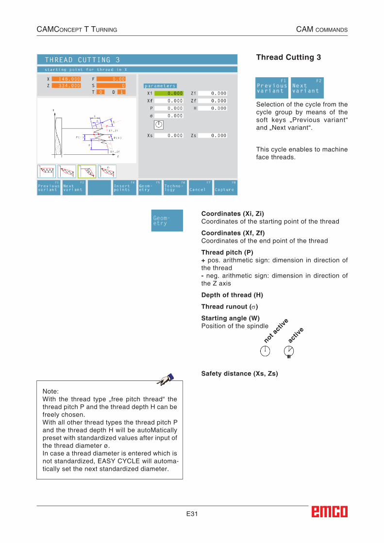
E31
Thread Cutting 3
Selection of the cycle from the cycle group by means of the soft keys „Previous variant“ and „Next variant“.
This cycle enables to machine face threads.
Coordinates (Xi, Zi)Coordinates of the starting point of the thread
Coordinates (Xf, Zf)Coordinates of the end point of the thread
Thread pitch (P)+ pos. arithmetic sign: dimension in direction of the thread- neg. arithmetic sign: dimension in direction of the Z axis
Depth of thread (H)
Thread runout (σ)
Starting angle (W)Position of the spindle
Safety distance (Xs, Zs)
not act
ive
activ
e
Note:With the thread type „free pitch thread“ the thread pitch P and the thread depth H can be freely chosen.With all other thread types the thread pitch P and the thread depth H will be autoMatically preset with standardized values after input of the thread diameter ø.In case a thread diameter is entered which is not standardized, EASY CYCLE will automa-tically set the next standardized diameter.
Geom-etry
CAMConCept t turning CAM CoMMAnds
##CAM:Gewindeschneiden203##
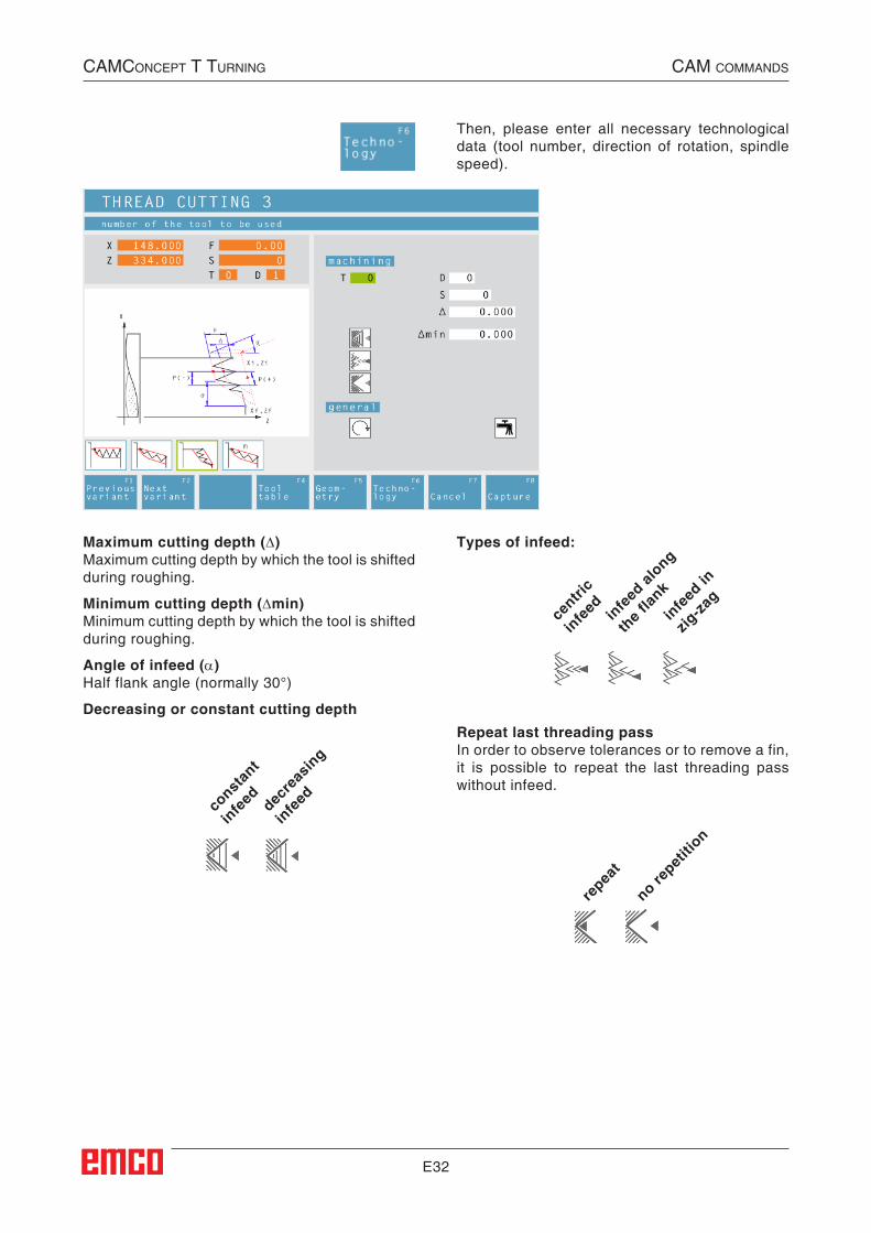
E32
Then, please enter all necessary technological data (tool number, direction of rotation, spindle speed).
Maximum cutting depth (∆)Maximum cutting depth by which the tool is shifted during roughing.
Minimum cutting depth (∆min)Minimum cutting depth by which the tool is shifted during roughing.
Angle of infeed (α)Half flank angle (normally 30°)
Decreasing or constant cutting depth
repea
t
no repet
ition
const
ant
infe
ed decre
asin
g
infe
ed
Types of infeed:
centri
c
infe
ed infe
ed al
ong
the f
lank
infe
ed in
zig-za
g
Repeat last threading passIn order to observe tolerances or to remove a fin, it is possible to repeat the last threading pass without infeed.
CAMConCept t turning CAM CoMMAnds

E33
Cycle Description1 According to the spindle's chosen direction of
rotation, a right or left thread will be turned.
2 The tool moves in rapid traverse to the safety distance (Xs, Zs).
3 The thread will be cut in several operations until the thread depth (H) is reached.
The icon-selected infeed is carried out: • at a constant infeed each time of (∆),
• at an infeed decreasing by (∆, ∆√2, ∆√3, ∆√4, ...). If a decreasing infeed is lower than the minimum infeed (∆min), at least (∆min) will be fed in.
The icon-selected infeed type will be taken into account.
4 If selected - the tool repeats the last threading operation.
5 At the end, the tool will be pulled back to the safety distance (Xs, Zs) in rapid traverse.
CAMConCept t turning CAM CoMMAnds
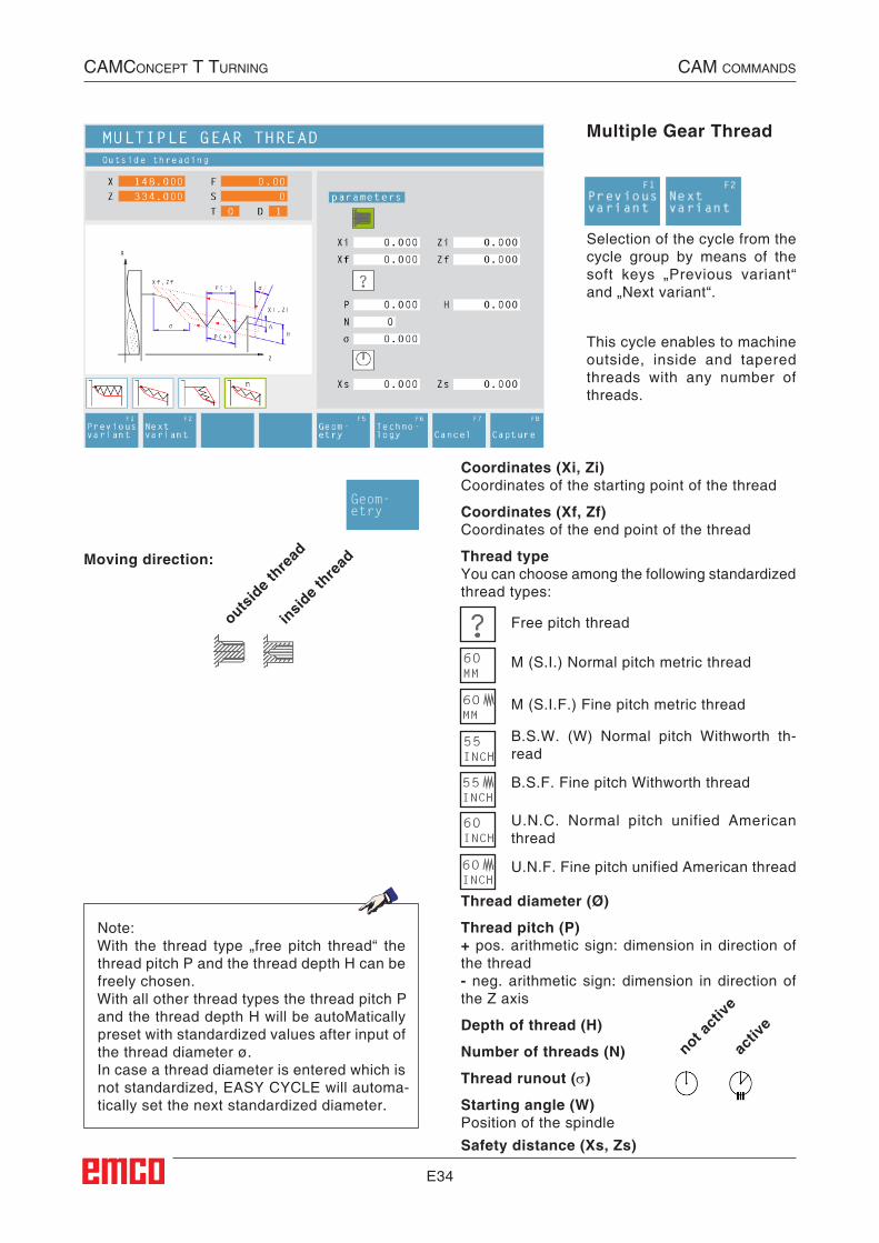
E34
Multiple Gear Thread
Selection of the cycle from the cycle group by means of the soft keys „Previous variant“ and „Next variant“.
U.N.F. Fine pitch unified American thread
U.N.C. Normal pitch unified American thread
B.S.F. Fine pitch Withworth thread
B.S.W. (W) Normal pitch Withworth th-read
M (S.I.F.) Fine pitch metric thread
M (S.I.) Normal pitch metric thread
Free pitch thread
Thread diameter (Ø)
Thread pitch (P)+ pos. arithmetic sign: dimension in direction of the thread- neg. arithmetic sign: dimension in direction of the Z axis
Depth of thread (H)
Number of threads (N)
Thread runout (σ)
Starting angle (W)Position of the spindle
Coordinates (Xi, Zi)Coordinates of the starting point of the thread
Coordinates (Xf, Zf)Coordinates of the end point of the thread
Thread typeYou can choose among the following standardized thread types:
Moving direction:
outsid
e thre
ad
insid
e thre
ad
Safety distance (Xs, Zs)
not act
ive
activ
e
This cycle enables to machine outside, inside and tapered threads with any number of threads.
Note:With the thread type „free pitch thread“ the thread pitch P and the thread depth H can be freely chosen.With all other thread types the thread pitch P and the thread depth H will be autoMatically preset with standardized values after input of the thread diameter ø.In case a thread diameter is entered which is not standardized, EASY CYCLE will automa-tically set the next standardized diameter.
Geom-etry
CAMConCept t turning CAM CoMMAnds
##CAM:Gewindeschneiden203##

E35
Then, please enter all necessary technological data (tool number, direction of rotation, spindle speed).
Maximum cutting depth (∆)Maximum cutting depth by which the tool is shifted during roughing.
Minimum cutting depth (∆min)Minimum cutting depth by which the tool is shifted during roughing.
Angle of infeed (α)Half flank angle (normally 30°)
Decreasing or constant cutting depth
repea
t
no repet
ition
c o n s t an t
infe
ed decre
asin
g
infe
ed
Types of infeed:
centri
c
infe
ed infe
ed al
ong
the f
lank
infe
ed in
zig-za
g
Repeat last threading passIn order to observe tolerances or to remove a fin, it is possible to repeat the last threading pass without infeed.
CAMConCept t turning CAM CoMMAnds

E36
Cycle Description1 According to the spindle's chosen direction of
rotation, a right or left thread will be turned.
2 The tool moves in rapid traverse to the safety distance (Xs, Zs).
3 The thread will be cut in several operations until the thread depth (H) is reached.
The icon-selected infeed is carried out: • at a constant infeed each time of (∆),
• at an infeed decreasing by (∆, ∆√2, ∆√3, ∆√4, ...). If a decreasing infeed is lower than the minimum infeed (∆min), at least (∆min) will be fed in.
The icon-selected infeed type will be taken into account.
4 If selected - the tool repeats the last threading operation.
5 At the end, the tool will be pulled back to the safety distance (Xs, Zs) in rapid traverse.
CAMConCept t turning CAM CoMMAnds

E37
CAMConCept t turning CAM CoMMAnds
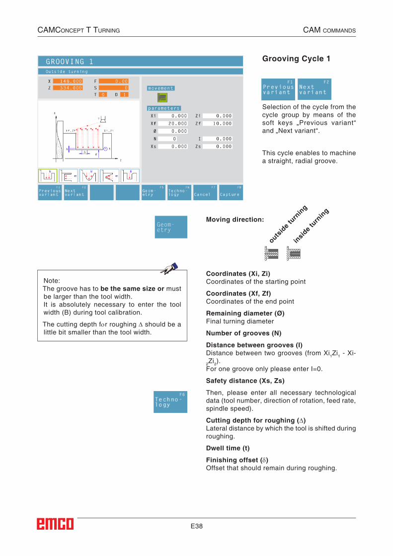
E38
Coordinates (Xi, Zi)Coordinates of the starting point
Coordinates (Xf, Zf)Coordinates of the end point
Remaining diameter (Ø)Final turning diameter
Number of grooves (N)
Distance between grooves (I)Distance between two grooves (from Xi1Zi1 - Xi-2Zi2). For one groove only please enter I=0.
Safety distance (Xs, Zs)
Then, please enter all necessary technological data (tool number, direction of rotation, feed rate, spindle speed).
Cutting depth for roughing (∆)Lateral distance by which the tool is shifted during roughing.
Dwell time (t)
Finishing offset (δ)Offset that should remain during roughing.
Grooving Cycle 1
Moving direction:
outsid
e turn
ing
insid
e turn
ing
Selection of the cycle from the cycle group by means of the soft keys „Previous variant“ and „Next variant“.
This cycle enables to machine a straight, radial groove.
Note:The groove has to be the same size or must be larger than the tool width.It is absolutely necessary to enter the tool width (B) during tool calibration.
The cutting depth for roughing ∆ should be a little bit smaller than the tool width.
Geom-etry
CAMConCept t turning CAM CoMMAnds
##CAM:Einstechen_1##
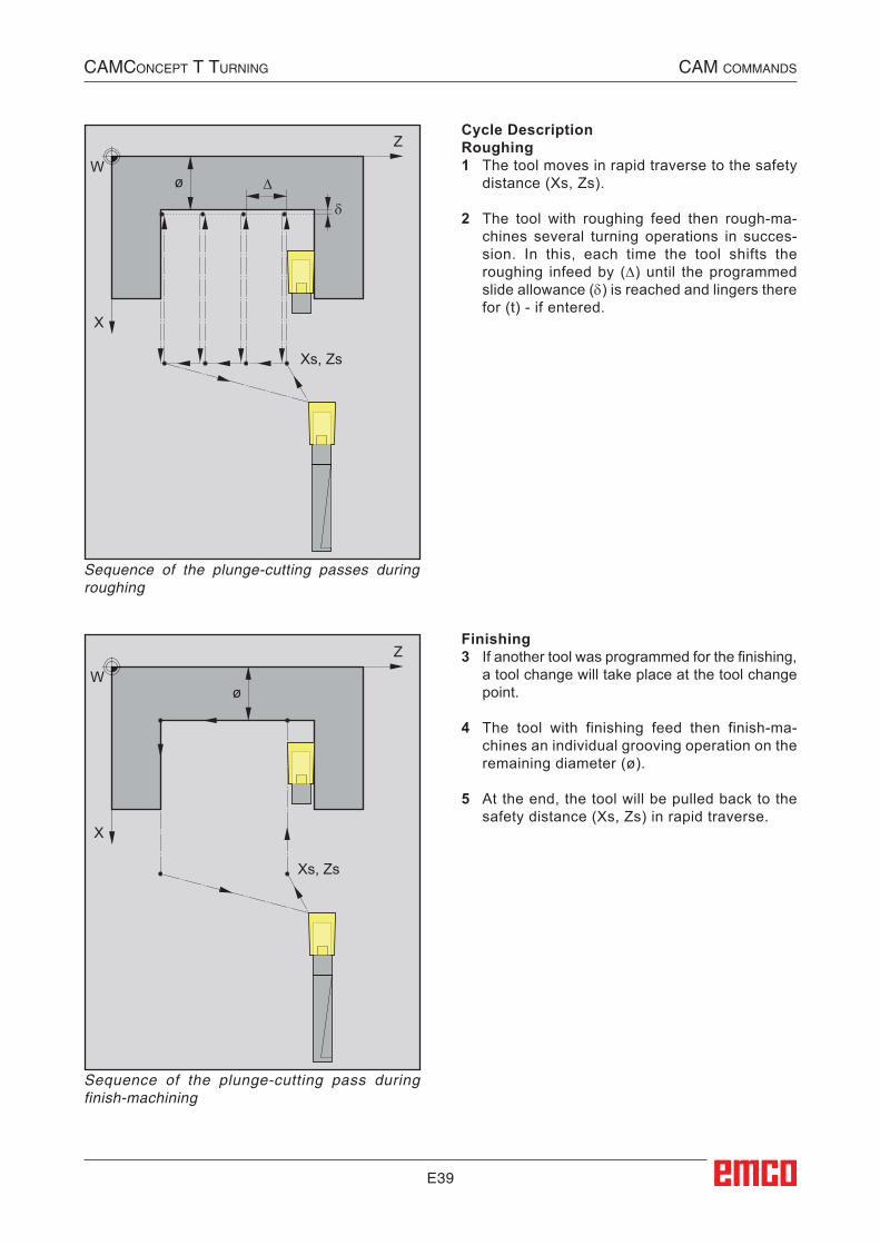
E39
Z
X
Xs, Zs
Wø ∆
δ
Z
X
Xs, Zs
Wø
Cycle DescriptionRoughing1 The tool moves in rapid traverse to the safety
distance (Xs, Zs).
2 The tool with roughing feed then rough-ma-chines several turning operations in succes-sion. In this, each time the tool shifts the roughing infeed by (∆) until the programmed slide allowance (δ) is reached and lingers there for (t) - if entered.
Finishing3 If another tool was programmed for the finishing,
a tool change will take place at the tool change point.
4 The tool with finishing feed then finish-ma-chines an individual grooving operation on the remaining diameter (ø).
5 At the end, the tool will be pulled back to the safety distance (Xs, Zs) in rapid traverse.
CAMConCept t turning CAM CoMMAnds
Sequence of the plunge-cutting passes during roughing
Sequence of the plunge-cutting pass during finish-machining
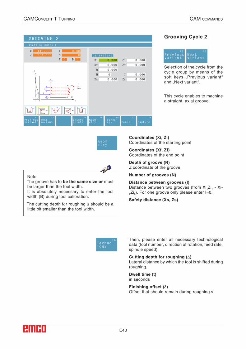
E40
Coordinates (Xi, Zi)Coordinates of the starting point
Coordinates (Xf, Zf)Coordinates of the end point
Depth of groove (R)Z coordinate of the groove
Number of grooves (N)
Distance between grooves (I)Distance between two grooves (from Xi1Zi1 - Xi-2Zi2). For one groove only please enter I=0.
Safety distance (Xs, Zs)
Grooving Cycle 2
Then, please enter all necessary technological data (tool number, direction of rotation, feed rate, spindle speed).
Cutting depth for roughing (∆)Lateral distance by which the tool is shifted during roughing.
Dwell time (t)in seconds
Finishing offset (δ)Offset that should remain during roughing.v
Selection of the cycle from the cycle group by means of the soft keys „Previous variant“ and „Next variant“.
This cycle enables to machine a straight, axial groove.
Note:The groove has to be the same size or must be larger than the tool width.It is absolutely necessary to enter the tool width (B) during tool calibration.
The cutting depth for roughing ∆ should be a little bit smaller than the tool width.
Geom-etry
CAMConCept t turning CAM CoMMAnds
##CAM:Einstechen_2##
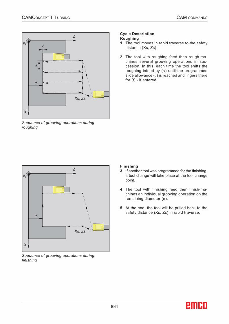
E41
δ
∆
X
Z
R
Xs, Zs
W
X
Z
R
Xs, Zs
W
Cycle DescriptionRoughing1 The tool moves in rapid traverse to the safety
distance (Xs, Zs).
2 The tool with roughing feed then rough-ma-chines several grooving operations in suc-cession. In this, each time the tool shifts the roughing infeed by (∆) until the programmed slide allowance (δ) is reached and lingers there for (t) - if entered.
Sequence of grooving operations during roughing
Sequence of grooving operations during finishing
Finishing3 If another tool was programmed for the finishing,
a tool change will take place at the tool change point.
4 The tool with finishing feed then finish-ma-chines an individual grooving operation on the remaining diameter (ø).
5 At the end, the tool will be pulled back to the safety distance (Xs, Zs) in rapid traverse.
CAMConCept t turning CAM CoMMAnds
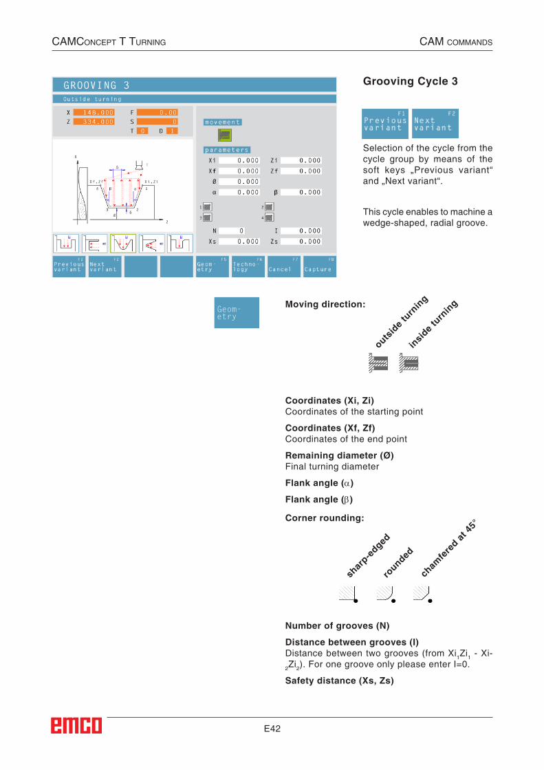
E42
Grooving Cycle 3
Selection of the cycle from the cycle group by means of the soft keys „Previous variant“ and „Next variant“.
This cycle enables to machine a wedge-shaped, radial groove.
Coordinates (Xi, Zi)Coordinates of the starting point
Coordinates (Xf, Zf)Coordinates of the end point
Remaining diameter (Ø)Final turning diameter
Flank angle (α)
Flank angle (β)
Number of grooves (N)
Distance between grooves (I)Distance between two grooves (from Xi1Zi1 - Xi-2Zi2). For one groove only please enter I=0.
Safety distance (Xs, Zs)
Moving direction:
outsid
e turn
ing
insid
e turn
ing
Corner rounding:
shar
p-edged
rounded
cham
fere
d at 45
°
Geom-etry
CAMConCept t turning CAM CoMMAnds
##CAM:Einstechen_3##
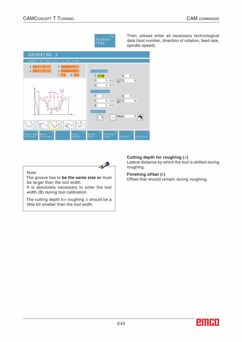
E43
Then, please enter all necessary technological data (tool number, direction of rotation, feed rate, spindle speed).
Cutting depth for roughing (∆)Lateral distance by which the tool is shifted during roughing.
Finishing offset (δ)Offset that should remain during roughing.
Note:The groove has to be the same size or must be larger than the tool width.It is absolutely necessary to enter the tool width (B) during tool calibration.
The cutting depth for roughing ∆ should be a little bit smaller than the tool width.
CAMConCept t turning CAM CoMMAnds

E44
Cycle DescriptionRoughing1 The tool moves in rapid traverse to the safety
distance (Xs, Zs).
2 The tool with roughing feed then rough-ma-chines several grooving operations in suc-cession. In this, each time the tool shifts the roughing infeed by (∆), taking into account the thread angles(α, β) until the programmed slide allowance (δ) is reached and lingers there for (t) - if entered.
Finishing3 If another tool was programmed for the finish-
ing, a tool change will take place at the tool change point.
4 The tool with finishing feed then finish-ma-chines an individual grooving operation on the remaining diameter (ø).
5 At the end, the tool will be pulled back to the safety distance (Xs, Zs) in rapid traverse.
CAMConCept t turning CAM CoMMAnds
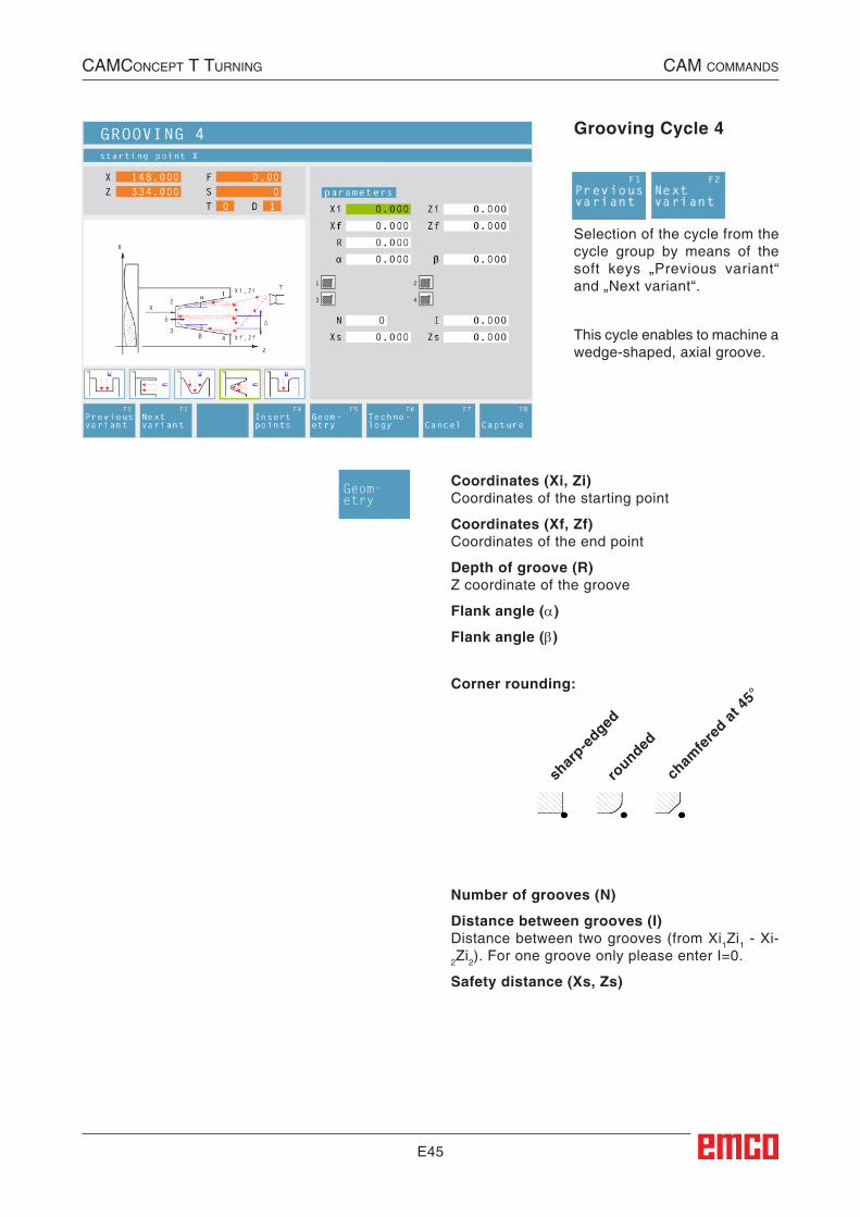
E45
Grooving Cycle 4
Selection of the cycle from the cycle group by means of the soft keys „Previous variant“ and „Next variant“.
This cycle enables to machine a wedge-shaped, axial groove.
Corner rounding:
shar
p-edged
rounded
cham
fere
d at 45
°
Coordinates (Xi, Zi)Coordinates of the starting point
Coordinates (Xf, Zf)Coordinates of the end point
Depth of groove (R)Z coordinate of the groove
Flank angle (α)
Flank angle (β)
Number of grooves (N)
Distance between grooves (I)Distance between two grooves (from Xi1Zi1 - Xi-2Zi2). For one groove only please enter I=0.
Safety distance (Xs, Zs)
Geom-etry
CAMConCept t turning CAM CoMMAnds
##CAM:Einstechen_4##
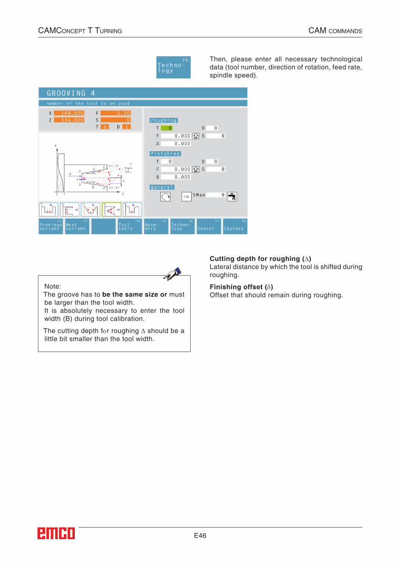
E46
Then, please enter all necessary technological data (tool number, direction of rotation, feed rate, spindle speed).
Cutting depth for roughing (∆)Lateral distance by which the tool is shifted during roughing.
Finishing offset (δ)Offset that should remain during roughing.
Note:The groove has to be the same size or must be larger than the tool width.It is absolutely necessary to enter the tool width (B) during tool calibration.
The cutting depth for roughing ∆ should be a little bit smaller than the tool width.
CAMConCept t turning CAM CoMMAnds

E47
Cycle DescriptionRoughing1 The tool moves in rapid traverse to the safety
distance (Xs, Zs).
2 The tool with roughing feed then rough-ma-chines several grooving operations in suc-cession. In this, each time the tool shifts the roughing infeed by (∆), taking into account the thread angles(α, β) until the programmed slide allowance (δ) is reached and lingers there for (t) - if entered.
Finishing3 If another tool was programmed for the finishing,
a tool change will take place at the tool change point.
4 The tool with finishing feed then finish-ma-chines an individual grooving operation on the remaining diameter (ø).
5 At the end, the tool will be pulled back to the safety distance (Xs, Zs) in rapid traverse.
CAMConCept t turning CAM CoMMAnds
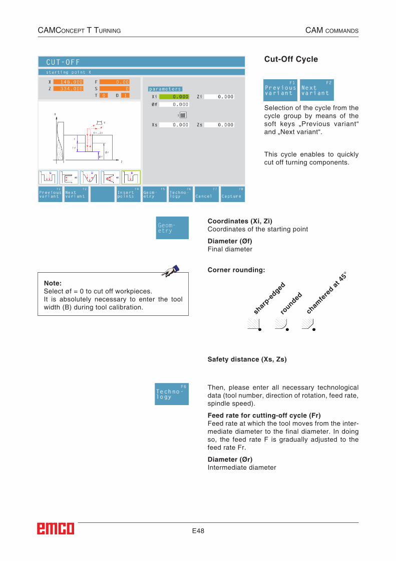
E48
Cut-Off Cycle
Selection of the cycle from the cycle group by means of the soft keys „Previous variant“ and „Next variant“.
This cycle enables to quickly cut off turning components.
Note:Select øf = 0 to cut off workpieces.It is absolutely necessary to enter the tool width (B) during tool calibration.
Corner rounding:
shar
p-edged
rounded
cham
fere
d at 45
°
Coordinates (Xi, Zi)Coordinates of the starting point
Diameter (Øf)Final diameter
Safety distance (Xs, Zs)
Then, please enter all necessary technological data (tool number, direction of rotation, feed rate, spindle speed).
Feed rate for cutting-off cycle (Fr)Feed rate at which the tool moves from the inter-mediate diameter to the final diameter. In doing so, the feed rate F is gradually adjusted to the feed rate Fr.
Diameter (Ør)Intermediate diameter
Geom-etry
CAMConCept t turning CAM CoMMAnds
##CAM:Trennzyklus##
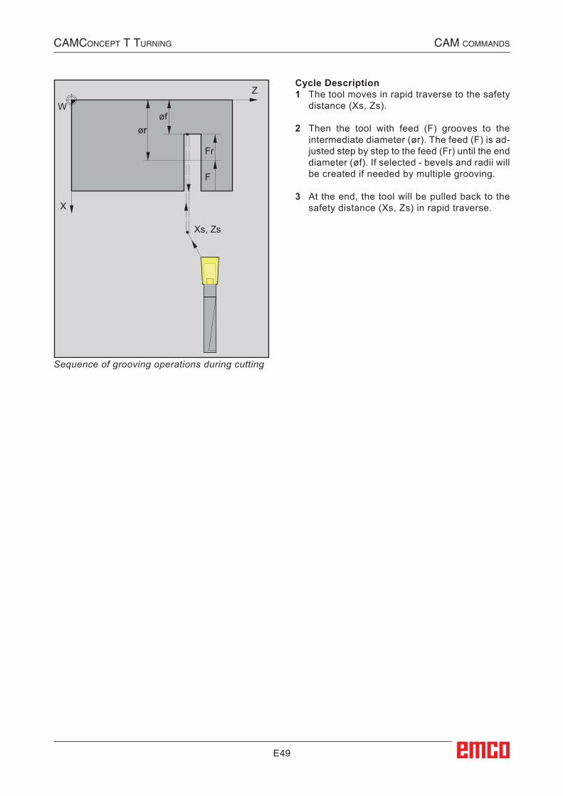
E49
Z
X
Xs, Zs
Wøf
F
Fr
ør
Cycle Description1 The tool moves in rapid traverse to the safety
distance (Xs, Zs).
2 Then the tool with feed (F) grooves to the intermediate diameter (ør). The feed (F) is ad-justed step by step to the feed (Fr) until the end diameter (øf). If selected - bevels and radii will be created if needed by multiple grooving.
3 At the end, the tool will be pulled back to the safety distance (Xs, Zs) in rapid traverse.
Sequence of grooving operations during cutting
CAMConCept t turning CAM CoMMAnds
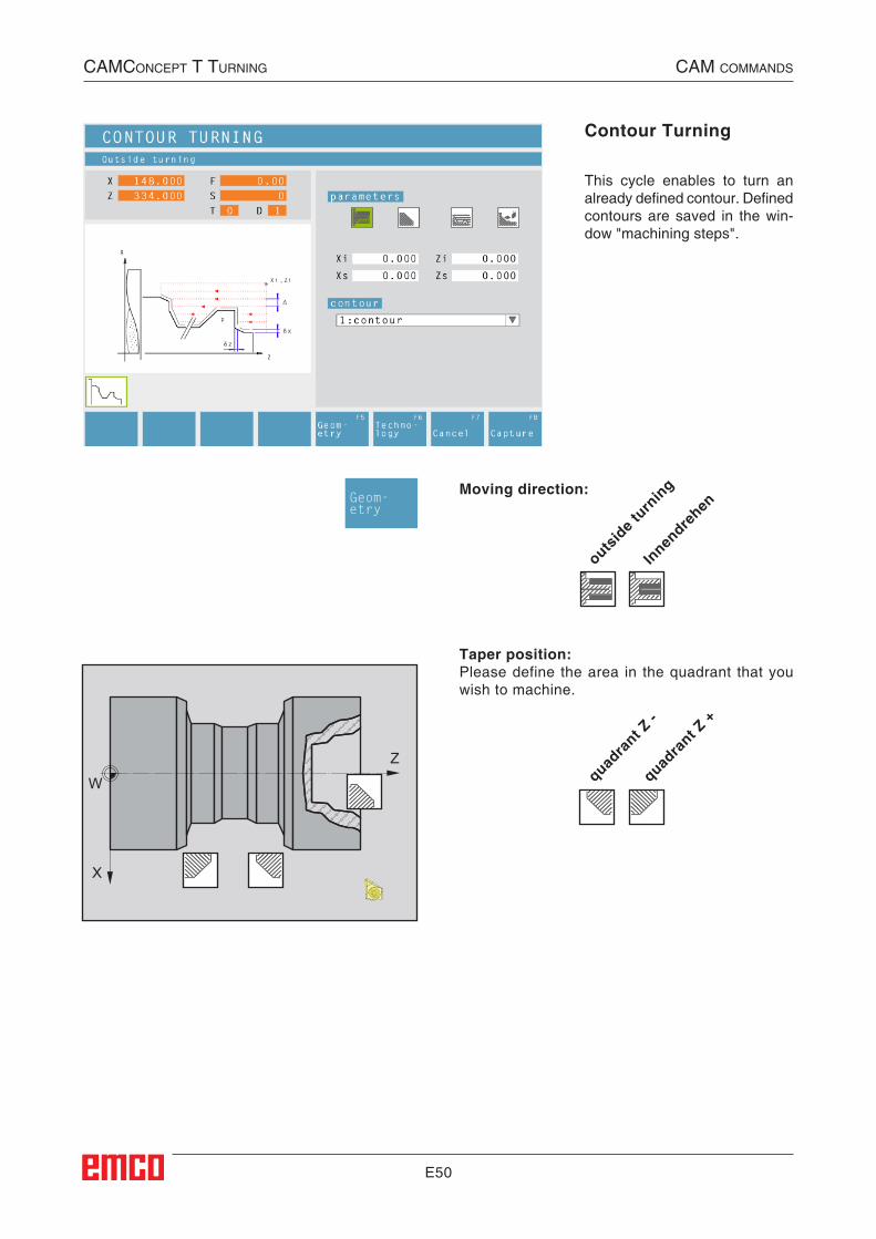
E50
Z
X
W
outsid
e turn
ing
Innen
drehen
Taper position:Please define the area in the quadrant that you wish to machine.
quadra
nt Z -
quadra
nt Z +
Moving direction:
Contour Turning
This cycle enables to turn an already defined contour. Defined contours are saved in the win-dow "machining steps".
Geom-etry
CAMConCept t turning CAM CoMMAnds
##CAM:Konturdrehen##
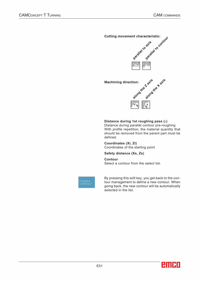
E51
Cutting movement characteristic:
parall
el to
axis
parall
el to
conto
ur
Machining direction:
along th
e Z ax
is
along th
e X ax
is
By pressing this soft key, you get back to the con-tour management to define a new contour. When going back, the new contour will be automatically selected in the list.
Distance during 1st roughing pass (ε)Distance during parallel contour pre-roughingWith profile repetition, the material quantity that should be removed from the parent part must be defined.
Coordinates (Xi, Zi)Coordinates of the starting point
Safety distance (Xs, Zs)
ContourSelect a contour from the select list.
Createcontour
CAMConCept t turning CAM CoMMAnds
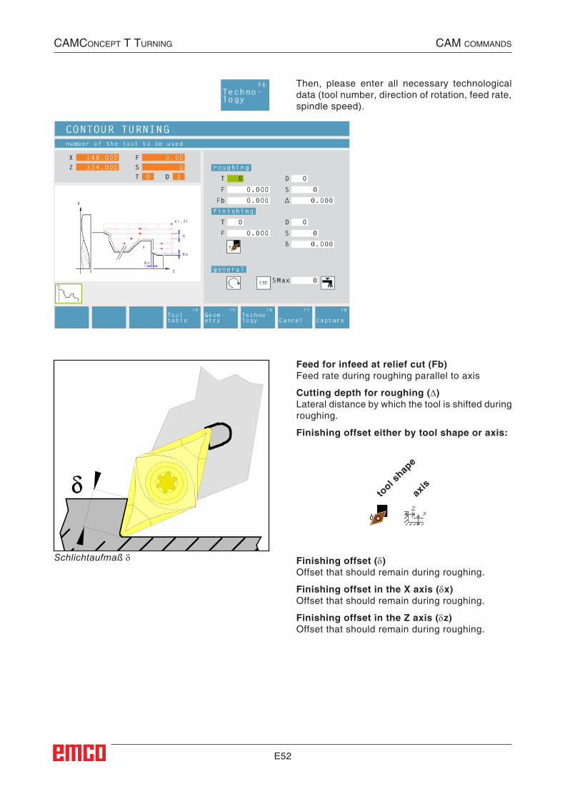
E52
Schlichtaufmaß δ
Then, please enter all necessary technological data (tool number, direction of rotation, feed rate, spindle speed).
Feed for infeed at relief cut (Fb)Feed rate during roughing parallel to axis
Cutting depth for roughing (∆)Lateral distance by which the tool is shifted during roughing.
Finishing offset either by tool shape or axis:
tool s
hape
axis
Finishing offset (δ)Offset that should remain during roughing.
Finishing offset in the X axis (δx)Offset that should remain during roughing.
Finishing offset in the Z axis (δz)Offset that should remain during roughing.
CAMConCept t turning CAM CoMMAnds
E53
Cycle DescriptionRoughing1 The tool moves in rapid traverse to the safety
distance (Xs, Zs).
2 Then the tool with roughing feed moves to the first contour point and rough-machines axis/contour parallel several turning/facing op-erations in succession. In this, each time the tool shifts the roughing infeed by (∆) until the programmed slide allowances (δ or δx, δz) are reached. With axis-parallel pre-roughing, the grooving feed (Fb) of the tool must be defined in the pockets.
Finishing3 If another tool was programmed for the finishing,
a tool change will take place at the tool change point.
4 Then the tool with finishing infeed finish-ma-chines the contour in an individual turning operation.
5 At the end, the tool will be pulled back to the safety distance (Xs, Zs) in rapid traverse.
CAMConCept t turning CAM CoMMAnds
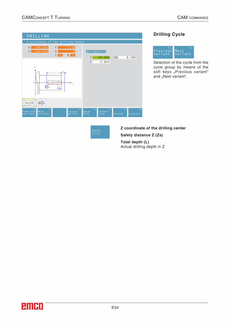
E54
Drilling Cycle
Selection of the cycle from the cycle group by means of the soft keys „Previous variant“ and „Next variant“.
Z coordinate of the drilling center
Safety distance Z (Zs)
Total depth (L)Actual drilling depth in Z
Geom-etry
CAMConCept t turning CAM CoMMAnds
##CAM:Bohren##
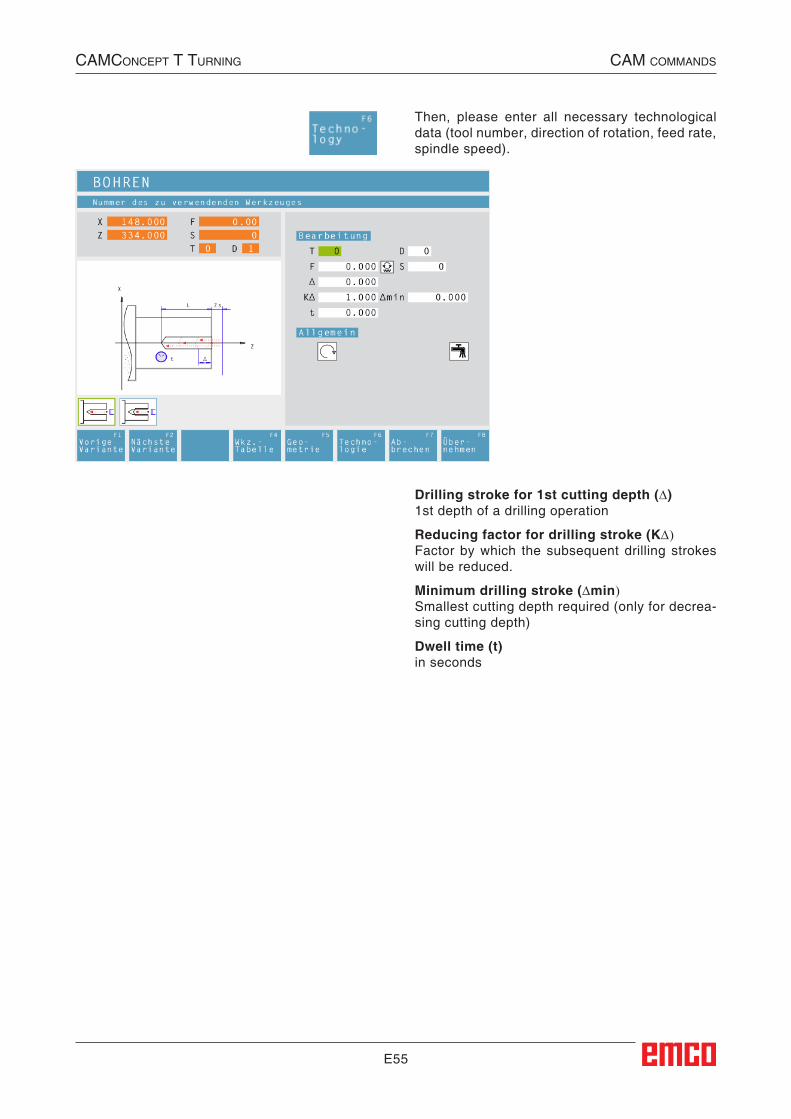
E55
Then, please enter all necessary technological data (tool number, direction of rotation, feed rate, spindle speed).
Drilling stroke for 1st cutting depth (∆)1st depth of a drilling operation
Reducing factor for drilling stroke (K∆)Factor by which the subsequent drilling strokes will be reduced.
Minimum drilling stroke (∆min)Smallest cutting depth required (only for decrea-sing cutting depth)
Dwell time (t)in seconds
CAMConCept t turning CAM CoMMAnds
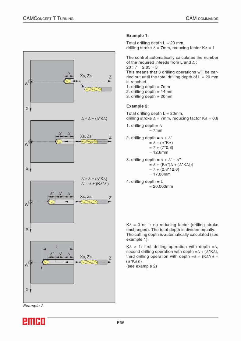
E56
X
W
∆Xs, Zs Z
X
W
∆∆'Xs, Zs Z
∆'= ∆ + (∆*K∆)
X
W
∆∆'∆''Xs, Zs Z
∆'= ∆ + (∆*K∆)∆''= ∆ + (K∆*∆')
X
W
∆
L
∆'∆''
t
Xs, Zs Z
Example 1:
Total drilling depth L = 20 mm,drilling stroke ∆ = 7mm, reducing factor K∆ = 1
The control automatically calculates the number of the required infeeds from L and ∆ :20 : 7 = 2.85 ≈ 3This means that 3 drilling operations will be car-ried out until the total drilling depth of L = 20 mm is reached.1. drilling depth = 7mm2. drilling depth = 14mm3. drilling depth = 20mm
Example 2:
Total drilling depth L = 20mm,drilling stroke ∆ = 7mm, reducing factor K∆ = 0,8
1. drilling depth= ∆ = 7mm
2. drilling depth = ∆ + ∆' = ∆ + (∆*K∆) = 7 + (7*0,8) = 12,6mm
3. drilling depth = ∆ + ∆' + ∆'' = ∆ + (K∆*(∆ + (∆*K∆))) = 7 + (0,8*12,6) = 17,08mm
4. drilling depth = L = 20.000mm
K∆ = 0 or 1: no reducing factor (drilling stroke unchanged). The total depth is divided equally.The cutting depth is automatically calculated (see example 1).
K∆ ≠ 1: first drilling operation with depth =∆, second drilling operation with depth =∆ + (∆*K∆), third drilling operation with depth =∆ + (K∆*(∆ + (∆*K∆)))(see example 2)
Example 2
CAMConCept t turning CAM CoMMAnds

E57
Cycle Description1 The tool moves in rapid traverse to the safety
distance (Xs, Zs).
2 The tool with roughing feed then taps several tapping operations in succession. In this, the tool moves to the safety distance and then advances by the calculated infeed in each case (see example). The tool dwells (t) at the hole depth - if entered.
3 At the end, the tool will be pulled back to the safety distance (Xs, Zs) in rapid traverse.
CAMConCept t turning CAM CoMMAnds
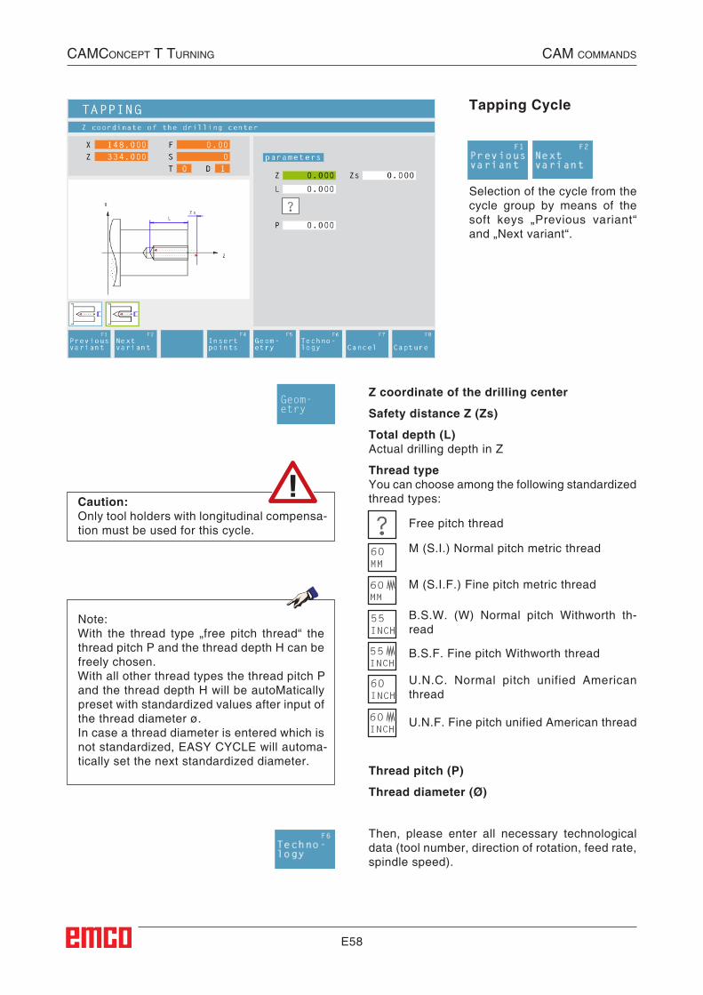
E58
Tapping Cycle
Selection of the cycle from the cycle group by means of the soft keys „Previous variant“ and „Next variant“.
Z coordinate of the drilling center
Safety distance Z (Zs)
Total depth (L)Actual drilling depth in Z
Thread typeYou can choose among the following standardized thread types:
Then, please enter all necessary technological data (tool number, direction of rotation, feed rate, spindle speed).
U.N.F. Fine pitch unified American thread
U.N.C. Normal pitch unified American thread
B.S.F. Fine pitch Withworth thread
B.S.W. (W) Normal pitch Withworth th-read
M (S.I.F.) Fine pitch metric thread
M (S.I.) Normal pitch metric thread
Free pitch thread
Thread pitch (P)
Thread diameter (Ø)
Note:With the thread type „free pitch thread“ the thread pitch P and the thread depth H can be freely chosen.With all other thread types the thread pitch P and the thread depth H will be autoMatically preset with standardized values after input of the thread diameter ø.In case a thread diameter is entered which is not standardized, EASY CYCLE will automa-tically set the next standardized diameter.
Geom-etry
Caution:Only tool holders with longitudinal compensa-tion must be used for this cycle.
##CAM:Gewindebohren##
CAMConCept t turning CAM CoMMAnds
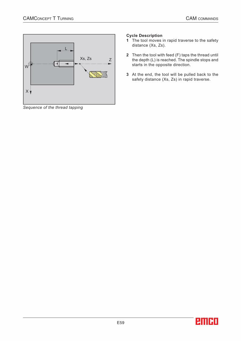
E59
X
W
L
Xs, Zs Z
Cycle Description1 The tool moves in rapid traverse to the safety
distance (Xs, Zs).
2 Then the tool with feed (F) taps the thread until the depth (L) is reached. The spindle stops and starts in the opposite direction.
3 At the end, the tool will be pulled back to the safety distance (Xs, Zs) in rapid traverse.
Sequence of the thread tapping
CAMConCept t turning CAM CoMMAnds
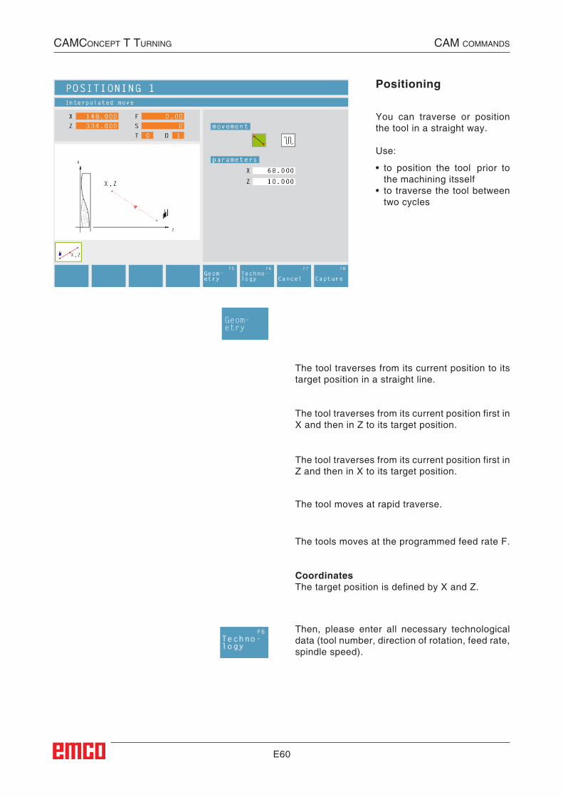
E60
Positioning
You can traverse or position the tool in a straight way.
Use:
• to position the tool prior to the machining itsself
• to traverse the tool between two cycles
The tool traverses from its current position to its target position in a straight line.
The tool traverses from its current position first in X and then in Z to its target position.
The tool traverses from its current position first in Z and then in X to its target position.
The tool moves at rapid traverse.
The tools moves at the programmed feed rate F.
CoordinatesThe target position is defined by X and Z.
Then, please enter all necessary technological data (tool number, direction of rotation, feed rate, spindle speed).
Geom-etry
CAMConCept t turning CAM CoMMAnds
##CAM:Positionieren##

E61
CAMConCept t turning CAM CoMMAnds
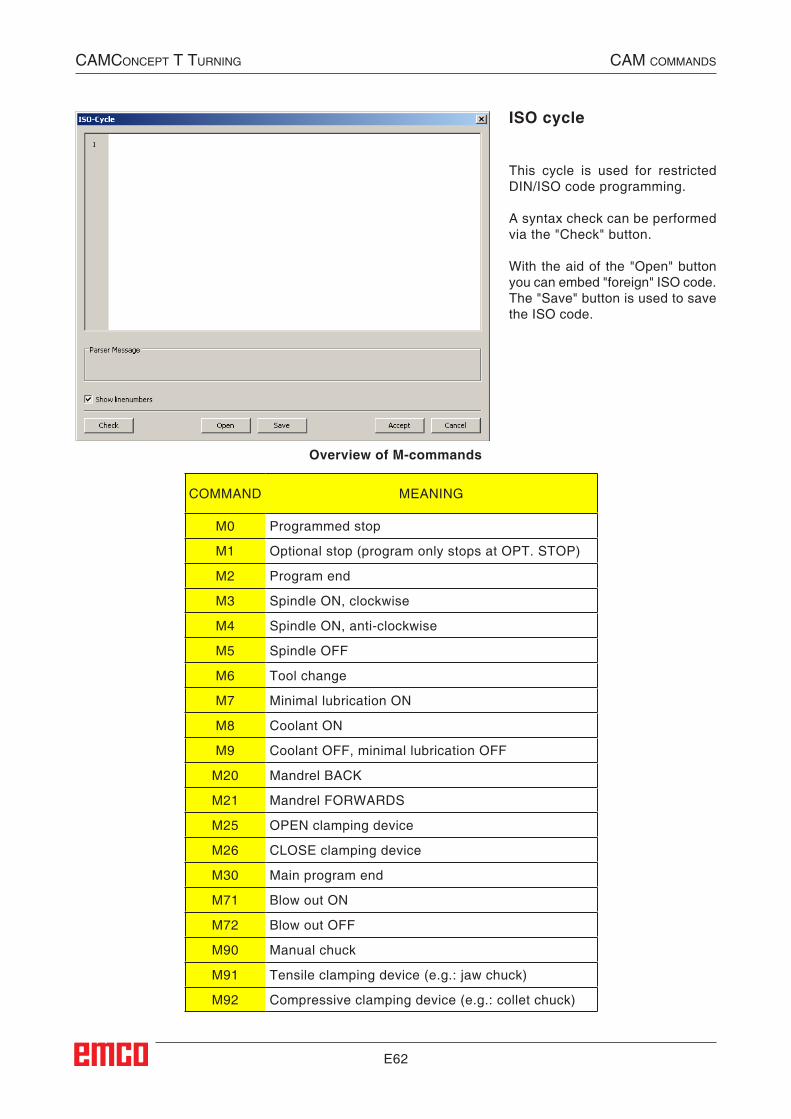
E62
CAMConCept t turning CAM CoMMAnds
Overview of M-commands
ISO cycle
COMMAND MEANING
M0 Programmed stop
M1 Optional stop (program only stops at OPT. STOP)
M2 Program end
M3 Spindle ON, clockwise
M4 Spindle ON, anti-clockwise
M5 Spindle OFF
M6 Tool change
M7 Minimal lubrication ON
M8 Coolant ON
M9 Coolant OFF, minimal lubrication OFF
M20 Mandrel BACK
M21 Mandrel FORWARDS
M25 OPEN clamping device
M26 CLOSE clamping device
M30 Main program end
M71 Blow out ON
M72 Blow out OFF
M90 Manual chuck
M91 Tensile clamping device (e.g.: jaw chuck)
M92 Compressive clamping device (e.g.: collet chuck)
This cycle is used for restricted DIN/ISO code programming.
A syntax check can be performed via the "Check" button.
With the aid of the "Open" button you can embed "foreign" ISO code. The "Save" button is used to save the ISO code.
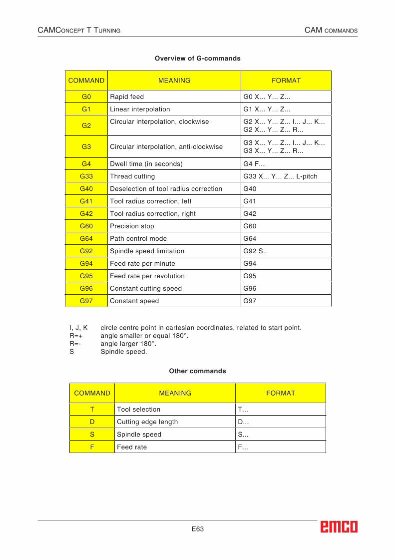
E63
I, J, K circle centre point in cartesian coordinates, related to start point.R=+ angle smaller or equal 180°.R=- angle larger 180°.S Spindle speed.
CAMConCept t turning CAM CoMMAnds
Overview of G-commands
COMMAND MEANING FORMAT
G0 Rapid feed G0 X... Y... Z...
G1 Linear interpolation G1 X... Y... Z...
G2 Circular interpolation, clockwise G2 X... Y... Z... I... J... K... G2 X... Y... Z... R...
G3 Circular interpolation, anti-clockwise G3 X... Y... Z... I... J... K... G3 X... Y... Z... R...
G4 Dwell time (in seconds) G4 F...
G33 Thread cutting G33 X... Y... Z... L-pitch
G40 Deselection of tool radius correction G40
G41 Tool radius correction, left G41
G42 Tool radius correction, right G42
G60 Precision stop G60
G64 Path control mode G64
G92 Spindle speed limitation G92 S..
G94 Feed rate per minute G94
G95 Feed rate per revolution G95
G96 Constant cutting speed G96
G97 Constant speed G97
Other commands
COMMAND MEANING FORMAT
T Tool selection T...
D Cutting edge length D...
S Spindle speed S...
F Feed rate F...
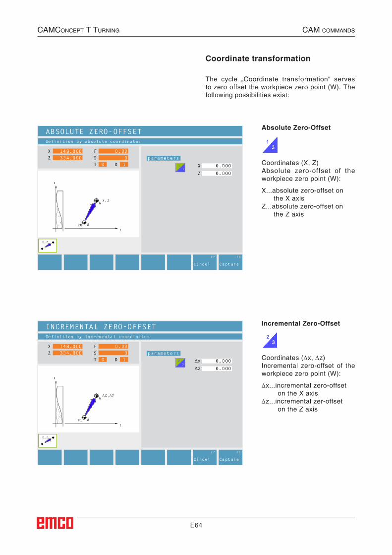
E64
Coordinate transformation
The cycle „Coordinate transformation“ serves to zero offset the workpiece zero point (W). The following possibilities exist:
Absolute Zero-Offset
Coordinates (X, Z)Absolute zero-offset of the workpiece zero point (W):
X...absolute zero-offset on the X axisZ...absolute zero-offset on the Z axis
Incremental Zero-Offset
Coordinates (∆x, ∆z)Incremental zero-offset of the workpiece zero point (W):
∆x...incremental zero-offset on the X axis∆z...incremental zer-offset on the Z axis
CAMConCept t turning CAM CoMMAnds
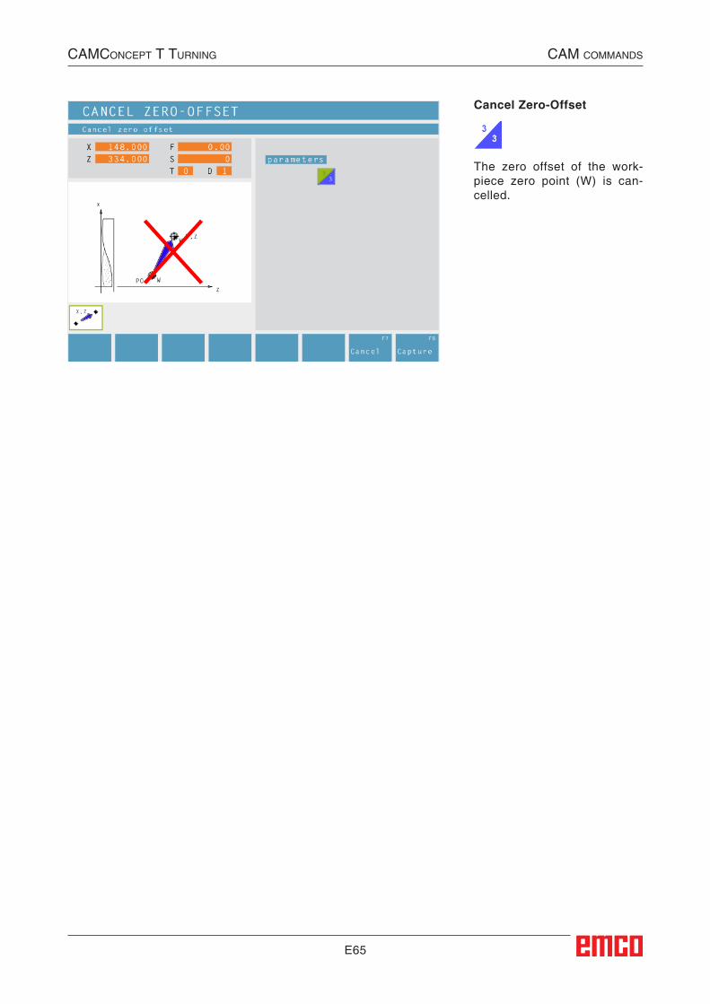
E65
Cancel Zero-Offset
The zero offset of the work-piece zero point (W) is can-celled.
CAMConCept t turning CAM CoMMAnds
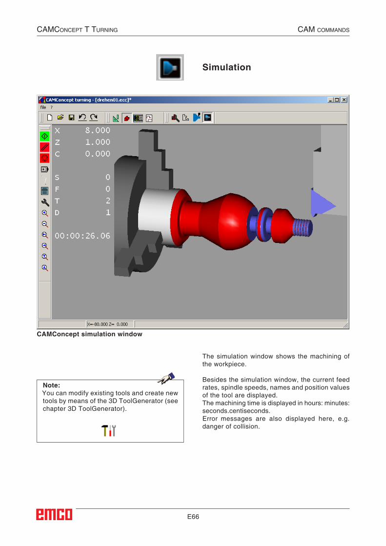
E66
Simulation
The simulation window shows the machining of the workpiece.
Besides the simulation window, the current feed rates, spindle speeds, names and position values of the tool are displayed.The machining time is displayed in hours: minutes: seconds.centiseconds.Error messages are also displayed here, e.g. danger of collision.
Note:You can modify existing tools and create new tools by means of the 3D ToolGenerator (see chapter 3D ToolGenerator).
CAMConCept t turning CAM CoMMAnds
CAMConcept simulation window
##Simulation##

E67
Simulation NC start
The simulation is started with this symbol.A CAMConcept project must be open in order to be able to start the simulation. The file name of the CAMConcept project being open at the moment is displayed in the upper center of the simulation window (e.g.: flange9.ecc).
Simulation NC reset
With this symbol the simulation and the CNC pro-gram are aborted and they return to their initial state.
Simulation NC stop
With this symbol the simulation and the CNC program are stopped. The simulation can be continued by means of the symbol "NC start".
Simulation single block on/off
This symbol enables to stop the simulation after every block.The simulation can be continued by means of the symbol "NC start".
CAMConCept t turning CAM CoMMAnds
##Einzelsatz_ein/aus##
##NC-Stop##
##NC-Reset##
##NC-Start##
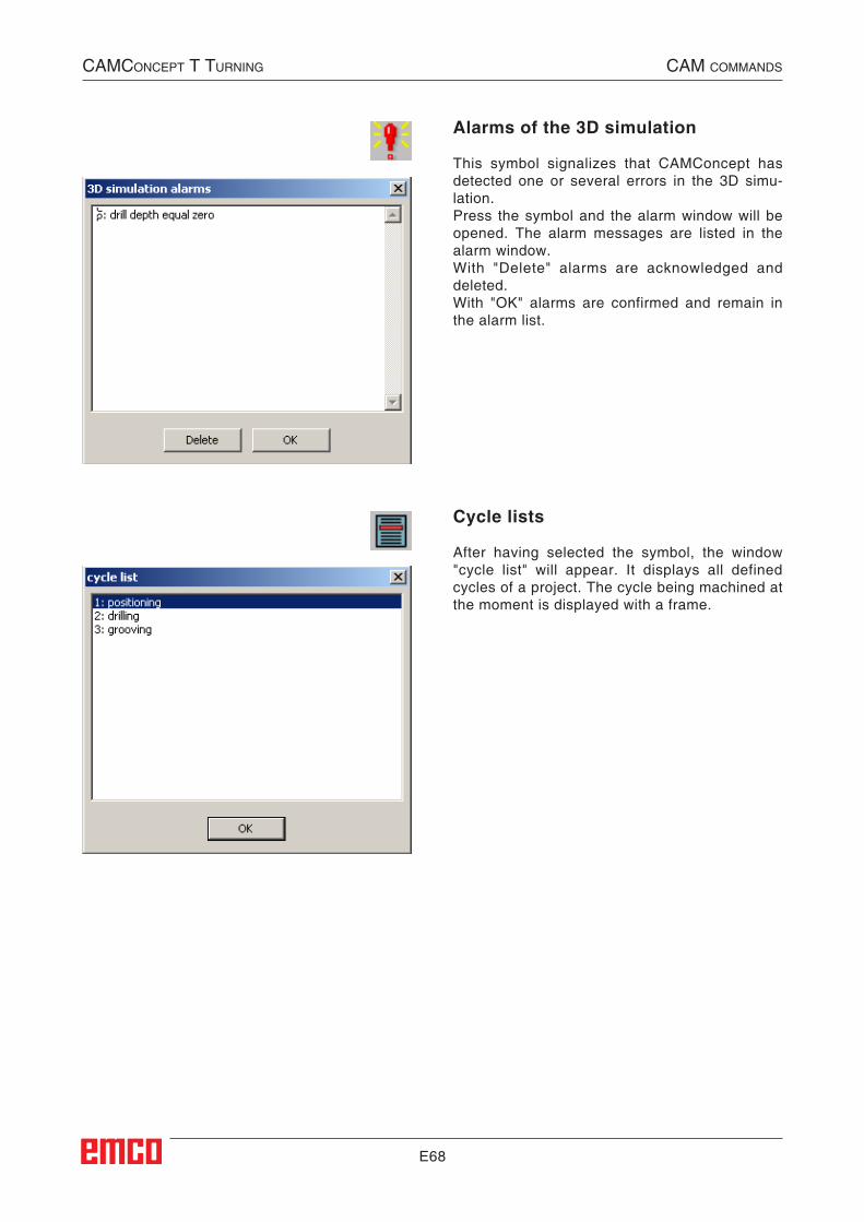
E68
Alarms of the 3D simulation
This symbol signalizes that CAMConcept has detected one or several errors in the 3D simu-lation.Press the symbol and the alarm window will be opened. The alarm messages are listed in the alarm window.With "Delete" alarms are acknowledged and deleted.With "OK" alarms are confirmed and remain in the alarm list.
Cycle lists
After having selected the symbol, the window "cycle list" will appear. It displays all defined cycles of a project. The cycle being machined at the moment is displayed with a frame.
CAMConCept t turning CAM CoMMAnds
##CAM:Zyklenliste##
##CAM:Alarme_der_3D_Simulation##
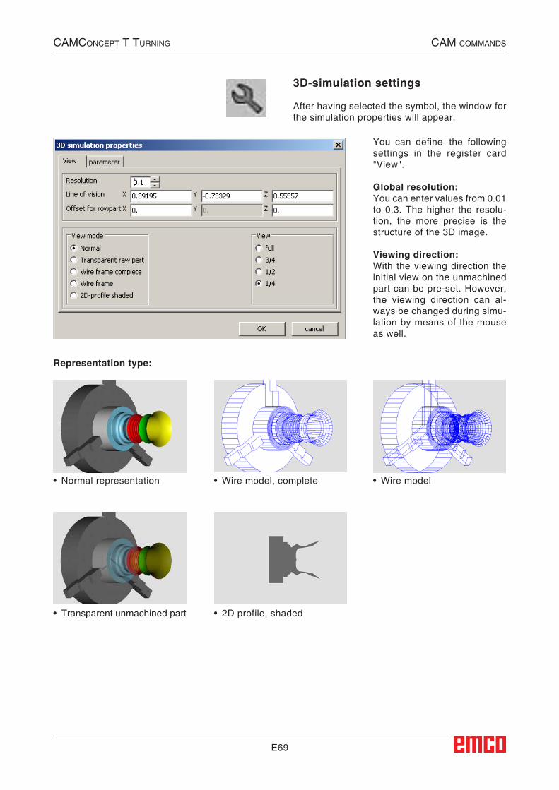
E69
You can define the following settings in the register card "View".
Global resolution:You can enter values from 0.01 to 0.3. The higher the resolu-tion, the more precise is the structure of the 3D image.
Viewing direction:With the viewing direction the initial view on the unmachined part can be pre-set. However, the viewing direction can al-ways be changed during simu-lation by means of the mouse as well.
3D-simulation settings
After having selected the symbol, the window for the simulation properties will appear.
CAMConCept t turning CAM CoMMAnds
Representation type:
• Wire model, complete • Wire model
• Transparent unmachined part • 2D profile, shaded
• Normal representation
##CAM:Einstellungen_3D_Simulation##
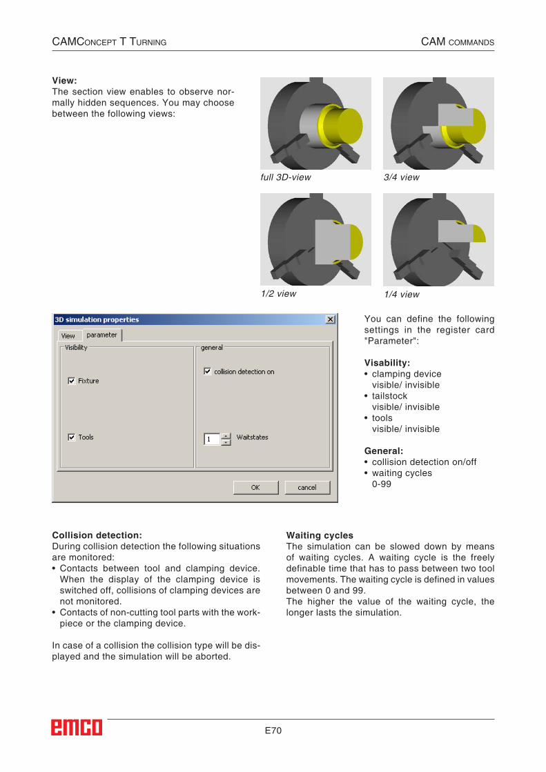
E70
You can define the following settings in the register card "Parameter":
Visability:• clamping device visible/ invisible• tailstock visible/ invisible• tools visible/ invisible
General:• collision detection on/off • waiting cycles 0-99
full 3D-view
1/2 view
3/4 view
1/4 view
View:The section view enables to observe nor-mally hidden sequences. You may choose between the following views:
Collision detection:During collision detection the following situations are monitored:• Contacts between tool and clamping device.
When the display of the clamping device is switched off, collisions of clamping devices are not monitored.
• Contacts of non-cutting tool parts with the work-piece or the clamping device.
In case of a collision the collision type will be dis-played and the simulation will be aborted.
Waiting cyclesThe simulation can be slowed down by means of waiting cycles. A waiting cycle is the freely definable time that has to pass between two tool movements. The waiting cycle is defined in values between 0 and 99.The higher the value of the waiting cycle, the longer lasts the simulation.
CAMConCept t turning CAM CoMMAnds
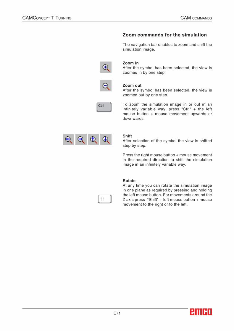
E71
Zoom commands for the simulation
The navigation bar enables to zoom and shift the simulation image.
Zoom inAfter the symbol has been selected, the view is zoomed in by one step.
Zoom outAfter the symbol has been selected, the view is zoomed out by one step.
To zoom the simulation image in or out in an infinitely variable way, press "Ctrl" + the left mouse button + mouse movement upwards or downwards.
ShiftAfter selection of the symbol the view is shifted step by step.
Press the right mouse button + mouse movement in the required direction to shift the simulation image in an infinitely variable way.
RotateAt any time you can rotate the simulation image in one plane as required by pressing and holding the left mouse button. For movements around the Z axis press "Shift" + left mouse button + mouse movement to the right or to the left.
Ctrl
CAMConCept t turning CAM CoMMAnds
##Zoombefehle_für_die_Simulation##
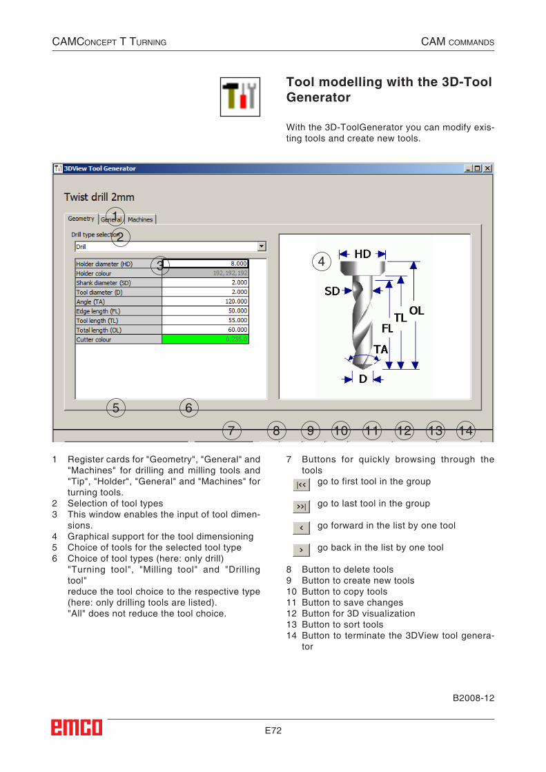
E72
Tool modelling with the 3D-Tool Generator
With the 3D-ToolGenerator you can modify exis-ting tools and create new tools.
1 Register cards for "Geometry", "General" and "Machines" for drilling and milling tools and "Tip", "Holder", "General" and "Machines" for turning tools.
2 Selection of tool types3 This window enables the input of tool dimen-
sions.4 Graphical support for the tool dimensioning5 Choice of tools for the selected tool type6 Choice of tool types (here: only drill) "Turning tool", "Milling tool" and "Drilling
tool" reduce the tool choice to the respective type
(here: only drilling tools are listed). "All" does not reduce the tool choice.
7 Buttons for quickly browsing through the tools go to first tool in the group
go to last tool in the group
go forward in the list by one tool
go back in the list by one tool
8 Button to delete tools9 Button to create new tools10 Button to copy tools11 Button to save changes12 Button for 3D visualization13 Button to sort tools14 Button to terminate the 3DView tool genera-
tor
1
2
3 4
5 6
7 98 1110 12 13 14
B2008-12
CAMConCept t turning CAM CoMMAnds
##Werkzeugmodellierung_mit_3D-ToolGenerator##
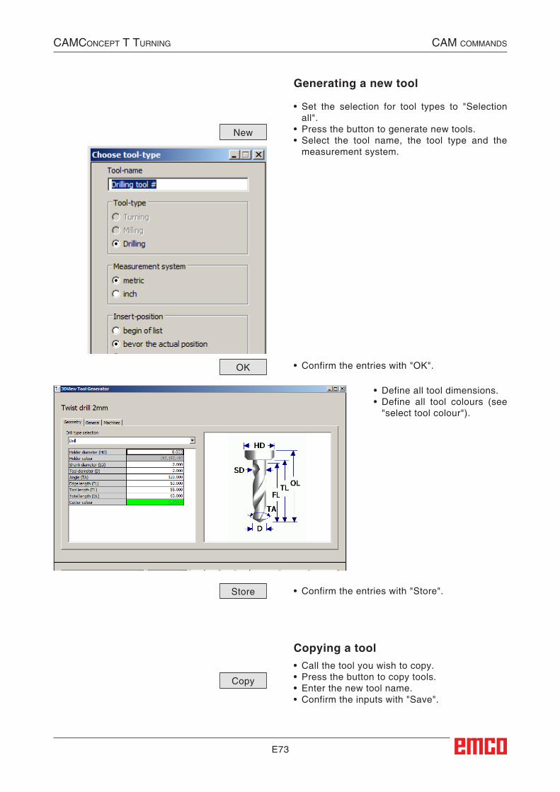
E73
Generating a new tool
• Set the selection for tool types to "Selection all".
• Press the button to generate new tools.• Select the tool name, the tool type and the
measurement system.
• Confirm the entries with "OK".
• Define all tool dimensions.• Define all tool colours (see
"select tool colour").
• Confirm the entries with "Store".
Copying a tool• Call the tool you wish to copy.• Press the button to copy tools.• Enter the new tool name.• Confirm the inputs with "Save".
New
Store
OK
Copy
CAMConCept t turning CAM CoMMAnds
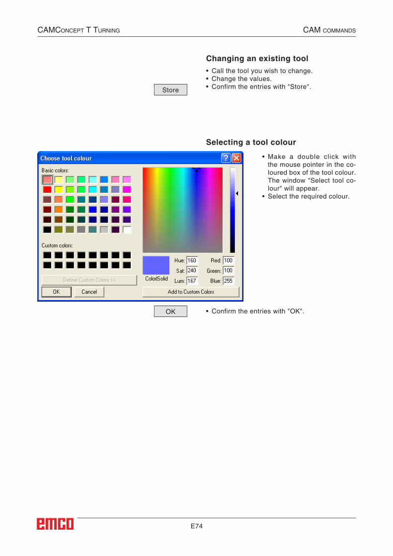
E74
Selecting a tool colour
• Make a double click with the mouse pointer in the co-loured box of the tool colour. The window "Select tool co-lour" will appear.
• Select the required colour.
• Confirm the entries with "OK".
Changing an existing tool• Call the tool you wish to change.• Change the values.• Confirm the entries with "Store".Store
OK
CAMConCept t turning CAM CoMMAnds
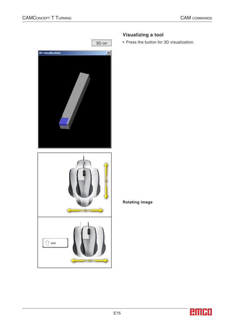
E75
Visualizing a tool• Press the button for 3D visualization.3D on
Rotating image
Shift
CAMConCept t turning CAM CoMMAnds
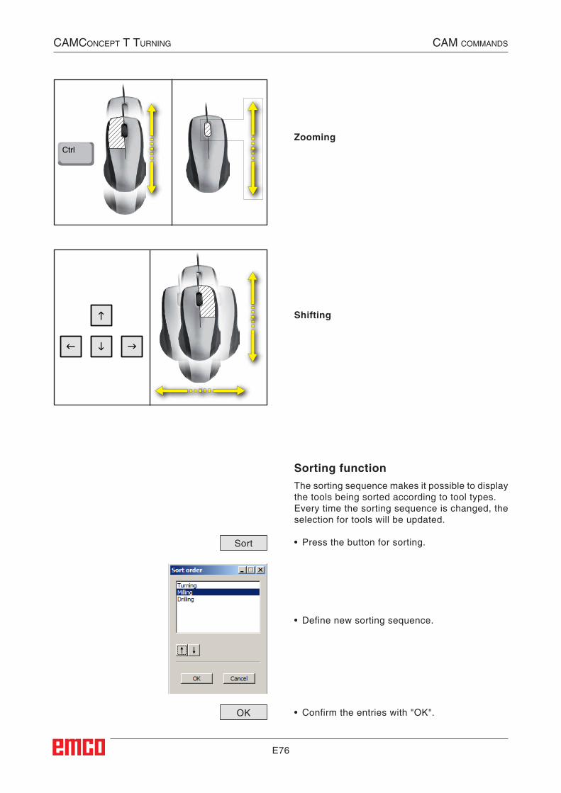
E76
CtrlZooming
Shifting
Sorting functionThe sorting sequence makes it possible to display the tools being sorted according to tool types.Every time the sorting sequence is changed, the selection for tools will be updated.
• Press the button for sorting.
• Define new sorting sequence.
• Confirm the entries with "OK".
Sort
OK
CAMConCept t turning CAM CoMMAnds
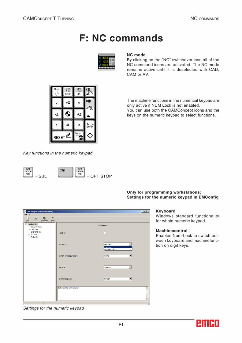
F1
= SBL = OPT STOP
KeyboardWindows standard functionality for whole numeric keypad.
MachinecontrolEnables Num-Lock to switch bet-ween keyboard and machinefunc-tion on digit keys.
Settings for the numeric keypad
Only for programming workstations:Settings for the numeric keypad in EMConfig
CAMConCept t turning nC CoMMAnds
F: NC commandsNC modeBy clicking on the "NC" switchover icon all of the NC command icons are activated. The NC mode remains active until it is deselected with CAD, CAM or AV.
The machine functions in the numerical keypad are only active if NUM Lock is not enabled.You can use both the CAMConcept icons and the keys on the numeric keypad to select functions.
Key functions in the numeric keypad
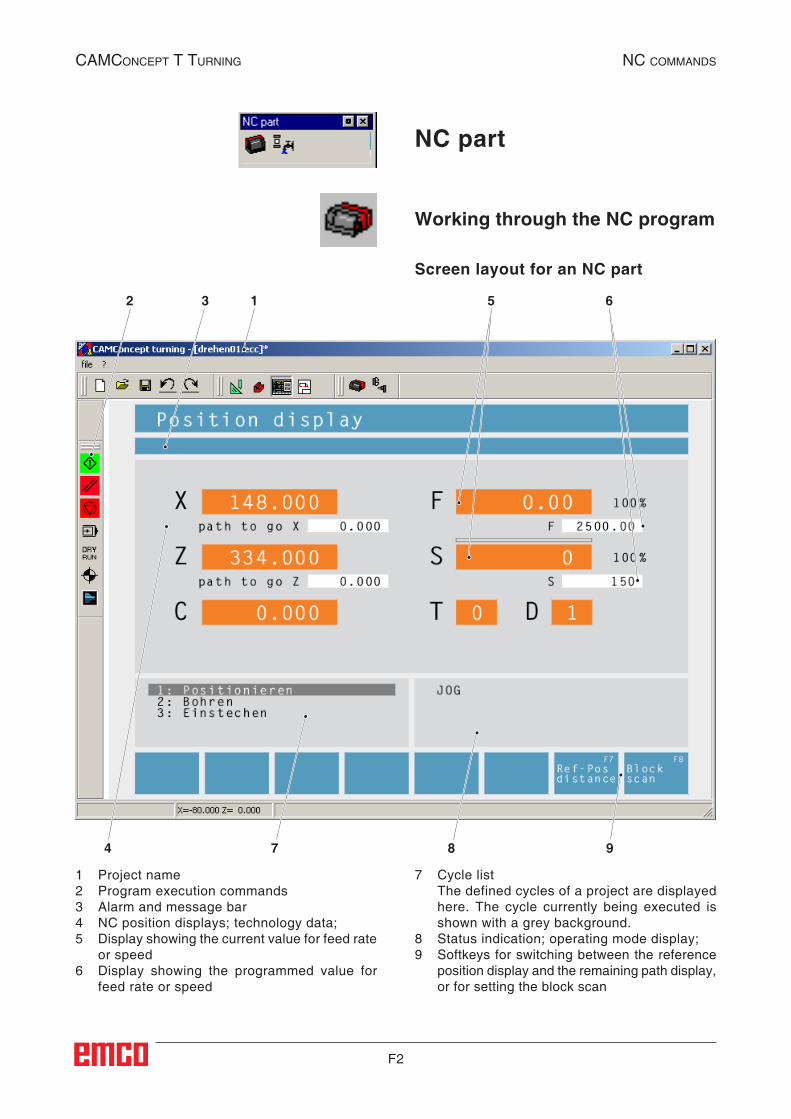
F2
4 7 8 9
2 3 1 5 6
CAMConCept t turning nC CoMMAnds
Working through the NC program
NC part
1 Project name2 Program execution commands3 Alarm and message bar4 NC position displays; technology data;5 Display showing the current value for feed rate
or speed6 Display showing the programmed value for
feed rate or speed
7 Cycle list The defined cycles of a project are displayed
here. The cycle currently being executed is shown with a grey background.
8 Status indication; operating mode display;9 Softkeys for switching between the reference
position display and the remaining path display, or for setting the block scan
Screen layout for an NC part
##NC-Teil##
##NC:Programmabarbeitung##
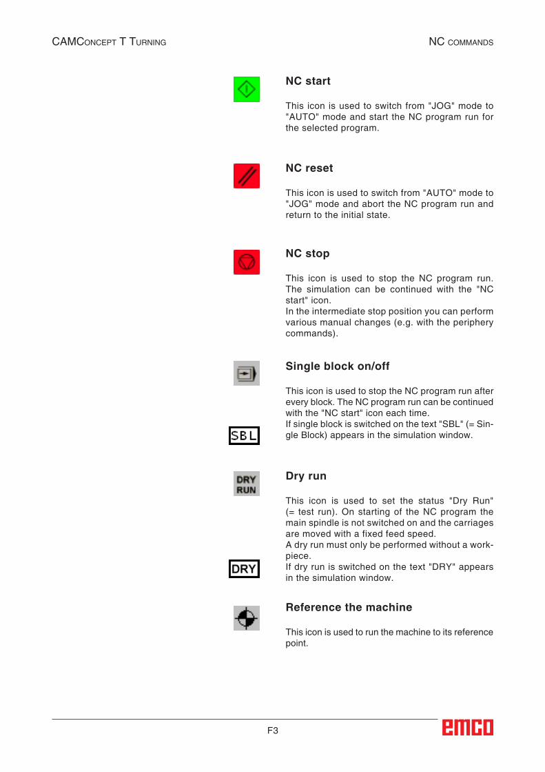
F3
CAMConCept t turning nC CoMMAnds
NC start
This icon is used to switch from "JOG" mode to "AUTO" mode and start the NC program run for the selected program.
NC reset
This icon is used to switch from "AUTO" mode to "JOG" mode and abort the NC program run and return to the initial state.
NC stop
This icon is used to stop the NC program run. The simulation can be continued with the "NC start" icon.In the intermediate stop position you can perform various manual changes (e.g. with the periphery commands).
Single block on/off
This icon is used to stop the NC program run after every block. The NC program run can be continued with the "NC start" icon each time.If single block is switched on the text "SBL" (= Sin-gle Block) appears in the simulation window.
Dry run
This icon is used to set the status "Dry Run" (= test run). On starting of the NC program the main spindle is not switched on and the carriages are moved with a fixed feed speed.A dry run must only be performed without a work-piece.If dry run is switched on the text "DRY" appears in the simulation window.
Reference the machine
This icon is used to run the machine to its reference point.
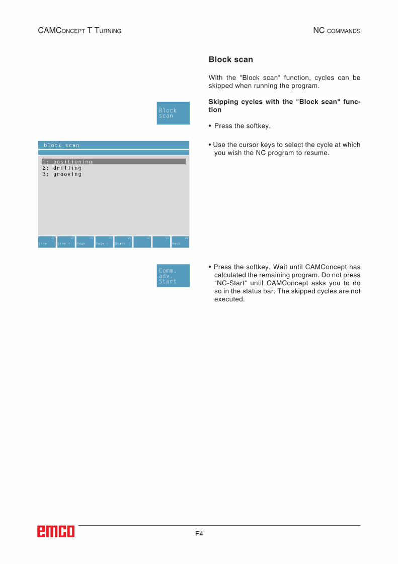
F4
CAMConCept t turning nC CoMMAnds
Block scan
With the "Block scan" function, cycles can be skipped when running the program.
Skipping cycles with the "Block scan" func-tion
• Press the softkey.
• Use the cursor keys to select the cycle at which you wish the NC program to resume.
• Press the softkey. Wait until CAMConcept has calculated the remaining program. Do not press "NC-Start" until CAMConcept asks you to do so in the status bar. The skipped cycles are not executed.
Blockscan
Comm. adv.Start
##NC:Satzvorlauf##
F5
CAMConCept t turning nC CoMMAnds
Periphery
The task of the periphery functions is to control the required NC machine accessories.The scope of displayed periphery functions depends on the installation. Functions which are not available are shown with a grey background.
Spindle counter-clockwise
This icon is used to switch on the main spindle anti-clockwise.
Spindle stop
This icon is used to switch off the main spindle.
Spindle clockwise
This icon is used to switch on the main spindle clockwise.
Open / close clamping device
This icon is used to open or close the clamping device.Please note that the clamping device can only be opened with the door open.
Mandrel forwards / back
These icons are used to move the mandrel forwards or backwards.
Blowing-out device on/off
This icon is used to switch the blowing-out device on for 3 seconds.
F6
CAMConCept t turning nC CoMMAnds
Open / close automatic door
These icons are used to open or close the machine door.Please note that the clamping device can only be opened with the door open.
Coolant on/off
This icon is used to switch the coolant pump on or off.
Next tool
This icon is used to advance the tool drum by 1 tool. This function can also be performed by pressing the key combination ALT + K.
Auxiliary drives on/off
These icons are used to switch the auxiliary drives on or off.
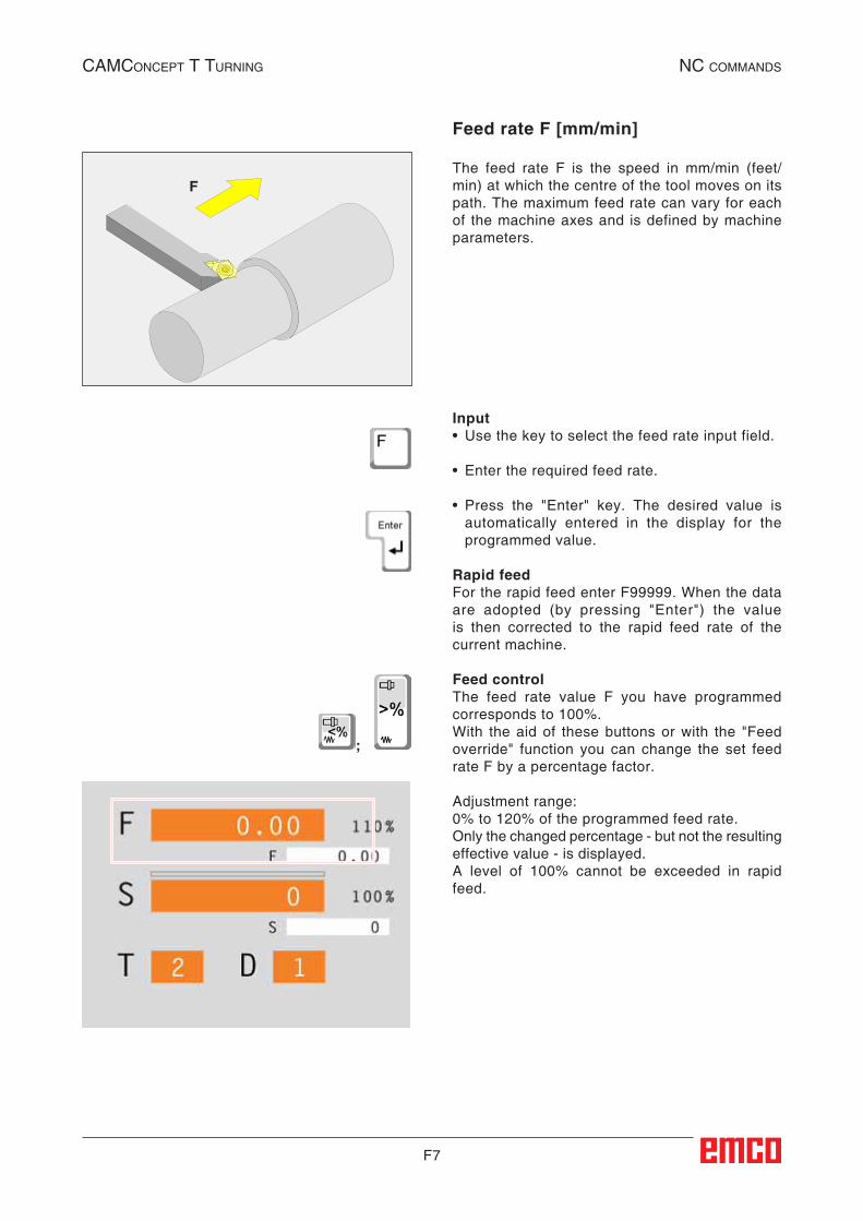
F7
F
CAMConCept t turning nC CoMMAnds
Feed rate F [mm/min]
The feed rate F is the speed in mm/min (feet/min) at which the centre of the tool moves on its path. The maximum feed rate can vary for each of the machine axes and is defined by machine parameters.
Input• Use the key to select the feed rate input field.
• Enter the required feed rate.
• Press the "Enter" key. The desired value is automatically entered in the display for the programmed value.
Rapid feedFor the rapid feed enter F99999. When the data are adopted (by pressing "Enter") the value is then corrected to the rapid feed rate of the current machine.
Feed controlThe feed rate value F you have programmed corresponds to 100%.With the aid of these buttons or with the "Feed override" function you can change the set feed rate F by a percentage factor.
Adjustment range:0% to 120% of the programmed feed rate.Only the changed percentage - but not the resulting effective value - is displayed.A level of 100% cannot be exceeded in rapid feed.
;
##NC:Vorschub_F##
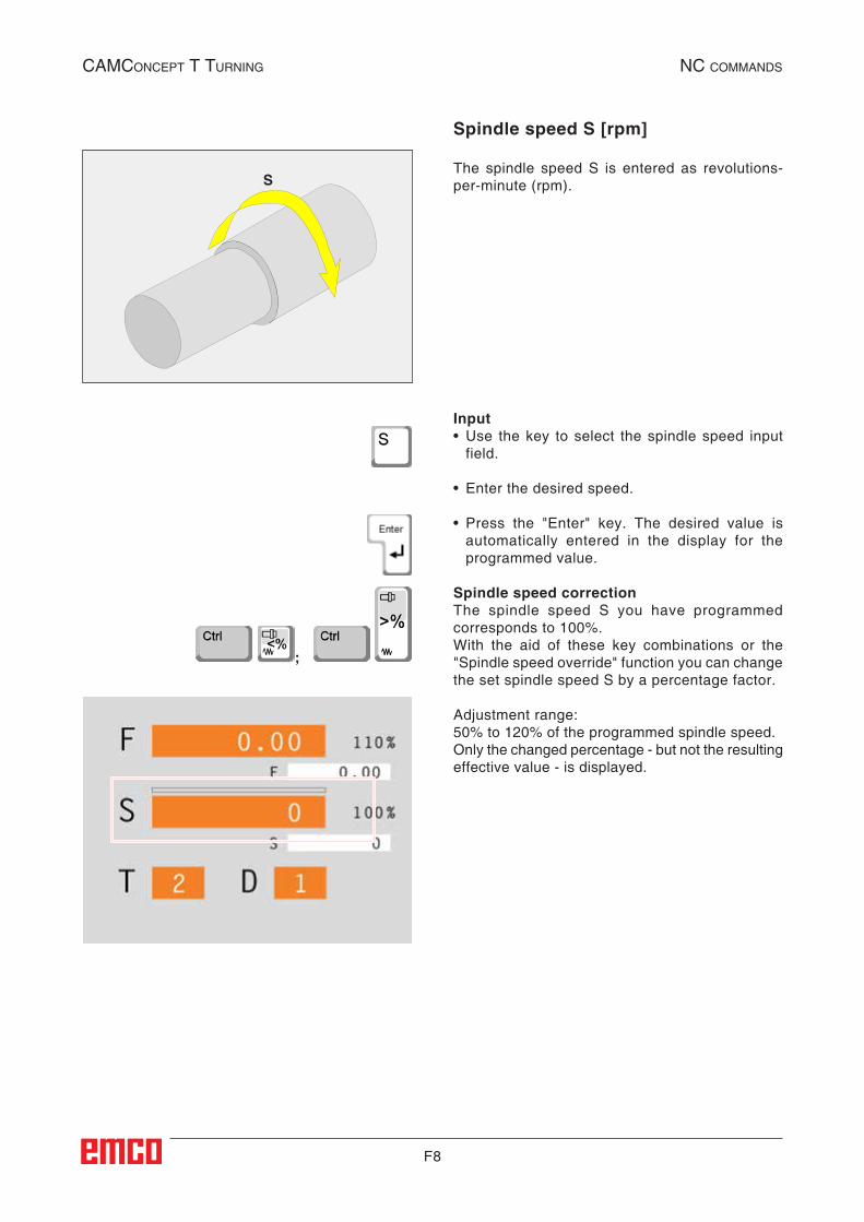
F8
S
CAMConCept t turning nC CoMMAnds
Spindle speed S [rpm]
The spindle speed S is entered as revolutions-per-minute (rpm).
Input• Use the key to select the spindle speed input
field.
• Enter the desired speed.
• Press the "Enter" key. The desired value is automatically entered in the display for the programmed value.
Spindle speed correctionThe spindle speed S you have programmed corresponds to 100%.With the aid of these key combinations or the "Spindle speed override" function you can change the set spindle speed S by a percentage factor.
Adjustment range:50% to 120% of the programmed spindle speed.Only the changed percentage - but not the resulting effective value - is displayed.
;
##NC:Spindeldrehzahl_S##
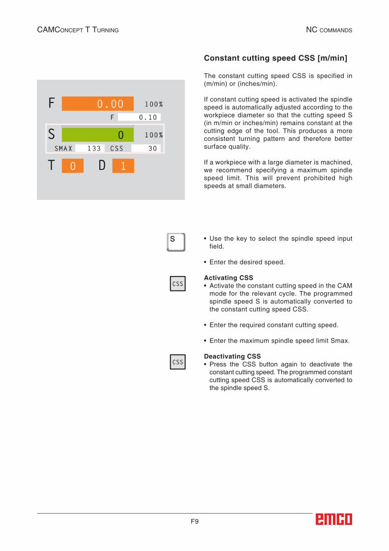
F9
CAMConCept t turning nC CoMMAnds
Constant cutting speed CSS [m/min]
The constant cutting speed CSS is specified in (m/min) or (inches/min).
If constant cutting speed is activated the spindle speed is automatically adjusted according to the workpiece diameter so that the cutting speed S (in m/min or inches/min) remains constant at the cutting edge of the tool. This produces a more consistent turning pattern and therefore better surface quality.
If a workpiece with a large diameter is machined, we recommend specifying a maximum spindle speed limit. This will prevent prohibited high speeds at small diameters.
• Use the key to select the spindle speed input field.
• Enter the desired speed.
Activating CSS• Activate the constant cutting speed in the CAM
mode for the relevant cycle. The programmed spindle speed S is automatically converted to the constant cutting speed CSS.
• Enter the required constant cutting speed.
• Enter the maximum spindle speed limit Smax.
Deactivating CSS• Press the CSS button again to deactivate the
constant cutting speed. The programmed constant cutting speed CSS is automatically converted to the spindle speed S.
CSS
CSS
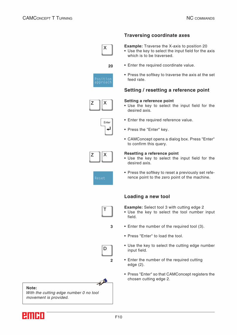
F10
CAMConCept t turning nC CoMMAnds
Loading a new tool
Example: Select tool 3 with cutting edge 2• Use the key to select the tool number input
field.
• Enter the number of the required tool (3).
• Press "Enter" to load the tool.
• Use the key to select the cutting edge number input field.
• Enter the number of the required cutting edge (2).
• Press "Enter" so that CAMConcept registers the chosen cutting edge 2.
Traversing coordinate axes
Example: Traverse the X-axis to position 20• Use the key to select the input field for the axis
which is to be traversed.
• Enter the required coordinate value.
• Press the softkey to traverse the axis at the set feed rate.
Setting / resetting a reference point
Setting a reference point• Use the key to select the input field for the
desired axis.
• Enter the required reference value.
• Press the "Enter" key.
• CAMConcept opens a dialog box. Press "Enter" to confirm this query.
Resetting a reference point• Use the key to select the input field for the
desired axis.
• Press the softkey to reset a previously set refe- rence point to the zero point of the machine.
Note:With the cutting edge number 0 no tool movement is provided.
20
Positionapproach
Reset
3
2
##NC:Koordinatenachsen_verfahren##
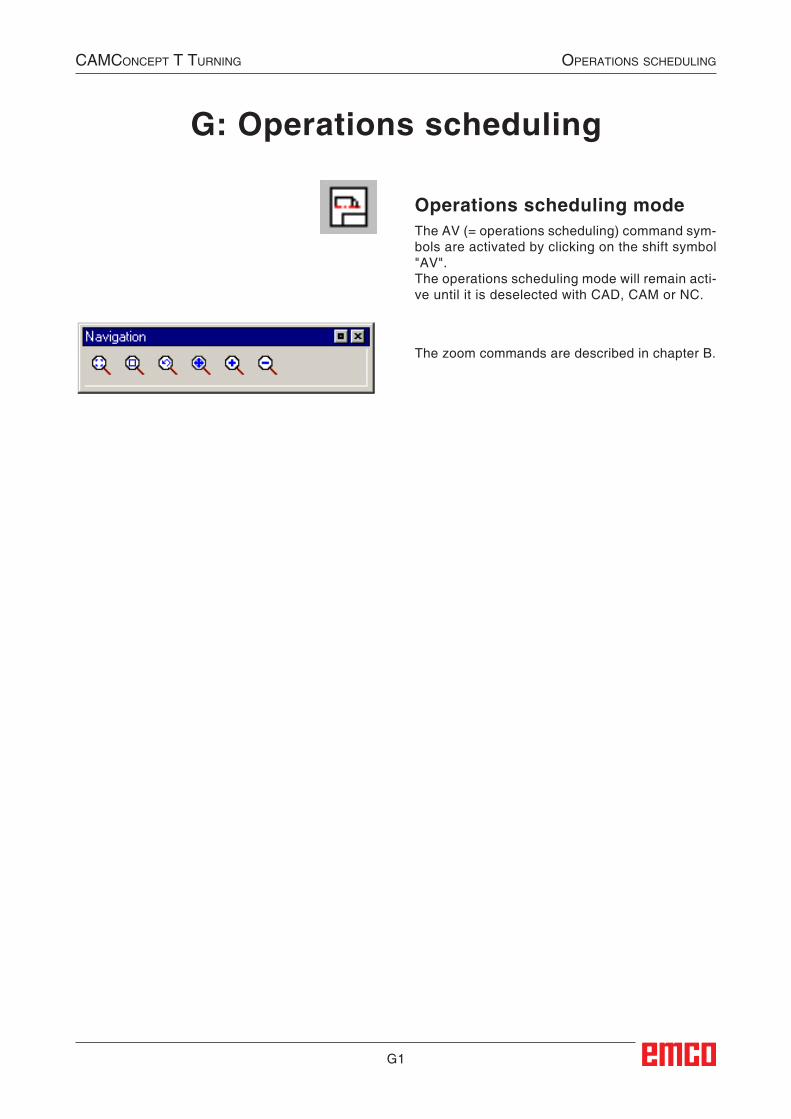
G1
Operations scheduling modeThe AV (= operations scheduling) command sym-bols are activated by clicking on the shift symbol "AV".The operations scheduling mode will remain acti-ve until it is deselected with CAD, CAM or NC.
CAMConCept t turning operAtions sCheduling
G: Operations scheduling
The zoom commands are described in chapter B.
##AV:Arbeitsvorbereitung_Modus##
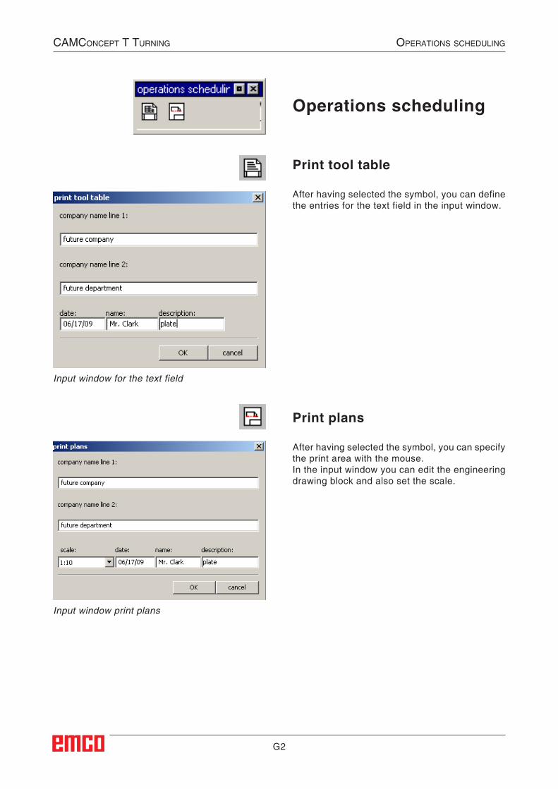
G2
Print tool table
After having selected the symbol, you can define the entries for the text field in the input window.
Print plans
After having selected the symbol, you can specify the print area with the mouse.In the input window you can edit the engineering drawing block and also set the scale.
Input window for the text field
Input window print plans
CAMConCept t turning operAtions sCheduling
Operations scheduling
##AV:Werkzeugtabelle_drucken##
##AV:Plaene_drucken##
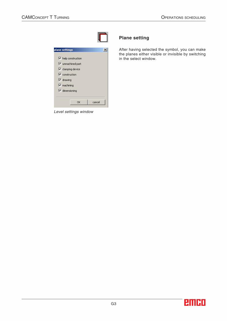
G3
Plane setting
After having selected the symbol, you can make the planes either visible or invisible by switching in the select window.
CAMConCept t turning operAtions sCheduling
Level settings window
##AV:Ebenen_Einstellungen##

G4
CAMConCept t turning operAtions sCheduling
H1
AlArms And messAges
H: Alarms and MessagesMachine Alarms 6000 - 7999These alarms will be triggered by the machines.There are different alarms for the different machines.The alarms 6000 - 6999 normally must be confirmed with RESET. The alarms 7000 - 7999 are messages which normally will disappear when the releasing situation is finished.
PC MILL 50 / 55 / 100 / 105 / 125 / 155Concept MILL 55 / 105 / 155
6000: EMERGENCY OFFThe EMERGENCY OFF key was pressed. Re-move the endangering situation and restart ma-chine and software.
6001: PLC-CYCLE TIME EXCEEDINGContact EMCO Service.
6002: PLC - NO PROGRAM CHARGEDContact EMCO Service.
6003: PLC - NO DATA UNITContact EMCO Service.
6004: PLC - RAM MEMORY FAILUREContact EMCO Service.
6005: OVERHEAT BRAKEMODULMain drive was braked too often, large changes of speed within a short time. E4.2 active
6006: OVERLOAD BRAKE RESISTORsee 6005
6007: SAFETY CIRCUIT FAULTAxis and main drive contactor with machine switched off not disabled. Contactor got stuck or contact error. E4.7 was not active during switch-on.
6008:MISSING CAN SUBSCRIBERCheck fuses or EMCO customer service.Contact EMCO Service.
6009: SAFETY CIRCUIT FAULTA running CNC program will be interrupted, the auxiliary drives will be stopped, the reference position will be lost.
6010: DRIVE X-AXIS NOT READYThe step motor board is defective or too hot, a fuse or cabling is defective.A running program will be stopped, the auxiliary drives will be switched off, the reference position will be lost.Check fuses or contact EMCO service.
6011: DRIVE Y-AXIS NOT READYsee alarm 6010.
6012: DRIVE Z-AXIS NOT READYsee alarm 6010.
6013: MAIN DRIVE NOT READYMain drive power supply defective, main drive too hot, fuse defective.A running program will be stopped, the auxilliary drives will be switched off.Check fuses or contact EMCO Service.
6014: NO MAIN SPINDLE SPEEDThis will be released, when the spindle speed is lower than 20 rpm because of overload.Alter cutting data (feed, infeed, spindle speed).The CNC program will be aborted, the auxilliary drives will be stopped.
6019: VICE TIME EXCEEDThe electric vice has not reached a stop position within 30 seconds.The control or the clamping device board are defective, the vice is stuck. Adjust the proximity switches of the stop position.
6020: VICE FAILUREWhen the electric vice is closed, the signal "clamping device clamped" of the clamping de-vice board has failed.The control, the clamping device board or the wiring are defective.
K 2017-07
H2
AlArms And messAges
6022: CLAMPING DEVICE BOARD DEFECTIVEThe signal "clamping device clamped" is con-stantly released, although no command has been given.Replace the board.
6024: MACHINE DOOR OPENThe door was opened while a machine movement. The program will be aborted.
6027: DOOR LIMIT SWITCH DEFECTIVEThe limit switch of the automatic door is dis-placed, defective, wrong cabled.Contact EMCO service.
6028: DOOR TIMEOUTThe automatic door stucks, the pressured air supply is insufficient, the limit switch is displaced.Check door, pressured air supply, limit switch or contact EMCO service.
6030: NO PART CLAMPEDNo workpiece inserted, vice cheek displaced, control cam displaced, hardware defective.Adjust or contact EMCO service.
6040: TOOL TURRET INDEX FAILUREAfter WZW procedure drum pressed down by Z-axis. Spindle position wrong or mechanical defect. E4.3=0 in lower state
6041: TOOL CHANGE TIMEOUTTool drum stucks (collision?), main drive not ready, fuse defective, hardware defective.A running CNC program will be stopped.Check for collisions, check fuses or contact EMCO service.
6043-6046: TOOL DISK POSITION FAULTPosition error of main drive, error of position supervising (inductive proximity switch defective or disadjusted, drum allowance), fuse defective, hardware defective.The Z axis could have been slipped out of the toothing while the machine was switched off.A running CNC program will be stopped.Contact EMCO service.
6047: TOOL DISK UNLOCKEDTool drum turned out of locked position, inductive proximity switch defective or disadjusted, fuse defective, hardware defective.A running CNC program will be interrupted.Contact EMCO service.When the tool drum is turned out of locked posi-tion (no defect), act as following:
Turn the drum into locking position manuallyChange into MANUAL (JOG) mode.Turn the key switch. Traverse the Z slide upwards, until the alarm disappears.
6048: DIVIDING TIME EXCEEDEDDividing head stucks, insufficient pressured air supply, hardware defective.Check for collision, check pressured air supply or contact EMCO service.
6049: INTERLOCKING TIME EXCEEDEDsee alarm 6048
6050: M25 AT RUNNING MAIN SPINDLECause: Programming mistake in NC program.A running program will be aborted.The auxilliary drives will be switched off.Remedy: Correct NC program
6064: DOOR AUTOMATIC NOT READYCause: pressure failure automatic door automatic door stucks mechanically limit switch for open end position defective security print circuits defect cabling defective fuses defectiveA running program will be aborted.The auxilliary drives will be switched off.Remedy: service automatic door
6069: CLAMPING FOR TANI NOT OPENWhen opening the clamping pressure switch does not fall within 400ms. Pressure switch defec-tive or mechanical problem. E22.3
6070: PRESSURE SWITCH FOR TANI MISS-ING
When closing the clamping pressure switch does not respond. No compressed air or mechanical problem. E22.3
6071: DIVIDING DEVICE NOT READYServo Ready Signal from frequency converter missing. Excess temperature drive TANI or fre-quency converter not ready for operation.
6072: VICE NOT READYAttempt to start the spindle with an open vice or without clamped workpiece.Vice stucks mechanically, insufficient com-pressed air supply, compressed air switch defec-tive, fuse defective, hardware defective.Check the fuses or contact EMCO service.
H3
AlArms And messAges
6073: DIVIDING DEVICE NOT READYCause: locking switch defective cabling defective fuses defectiveA running program will be aborted.The auxilliary drives will be switched off.Remedy: service automatic dividing device lock the dividing device
6074: DIVIDING TIME EXCEEDEDCause: dividing device stucks mechanically locking switch defective cabling defective fuses defective insufficient compressed-air supply.A running program will be aborted.The auxilliary drives will be switched off.Remedy: Check for collision, check the compressed-
air supply or contact the EMCO service.
6075: M27 AT RUNNING MAIN SPINDLECause: Programming mistake in NC program.A running program will be aborted.The auxilliary drives will be switched off.Remedy: Correct NC program
6110: 5TH AXIS NOT CONNECTEDCause: 4th/5th axis was selected in EMConfig, but
not connected electrically.Remedy: Connect 4th/5th axis or deselect in EM-
Config.
6111: 5TH AXIS CONNECTEDCause: 4th/5th axis was deselected in EMConfig,
but is electrically connected.Remedy: Remove 4th/5th axis from machine or
select in EMConfig.
6112: MOTOR PROTECTION RELEASEDCause: A motor protection switch has triggered.
A possibly active NC program is stopped immediately.
Remedy: Check the device connected to the motor protection switch and switch on again. If recurring, contact EMCO service depart-ment.
7000: INVALID TOOL NUMBER PROGRAMMEDThe tool position was programmed larger than 10.The CNC program will be stopped.Interrupt program with RESET and correct the program.
7001: NO M6 PROGRAMMEDFor an automatic tool change you also have to program a M6 after the T word.
7007: FEED STOP!The axes have been stopped by the robotics in-terface (robotics entry FEEDHOLD).
7016: SWITCH ON AUXILIARY DRIVESThe auxiliary drives are off. Press the AUX ON key for at least 0.5 sec. (to avoid accidentally switching on) to switch on the auxiliary drives.
7017: REFERENCE MACHINEApproach the reference point.When the reference point is not active, manual movements are possible only with key switch at position "setting operation".
7018: TURN KEY SWITCHWith NC-Start the key switch was in position "set-ting operation".NC-Start is locked.Turn the key switch in the position "automatic" to run a program.
7020: SPECIAL OPERATION MODE ACTIVESpecial operation mode: The machine door is opened, the auxiliary drives are switched on, the key switch is in position "setting operation" and the consent key is pressed.Manual traversing the axes is possible with open door. Swivelling the tool turret is not possible with open door. Running a CNC program is possible only with standing spindle (DRYRUN) and SIN-GLE block operation.For safety: If the consent key is pressed for more than 40 sec. the function of this key is interrupted, the consent key must be released and pressed again.
7021: INITIALIZE TOOL TURRETThe tool turret operating was interrupted.No traversing operation is possible.Press tool turret key in JOG operation. Message occurs after alarm 6040.
7022: INITIALIZE TOOL TURRET!see 7021
7023: WAITING TIME MAIN DRIVE!The LENZE frequency converter has to be sepa-rated from the mains supply for at least 20 sec-onds before you are allowed to switch it on again. This message will appear when the door is quickly openend/ closed (under 20 seconds).
7038: LUBRICATION SYSTEM FAULTThe pressure switch is defective or gagged.NC-Start is locked. This can be reset only by switching off and on the machine.Contact EMCO service.
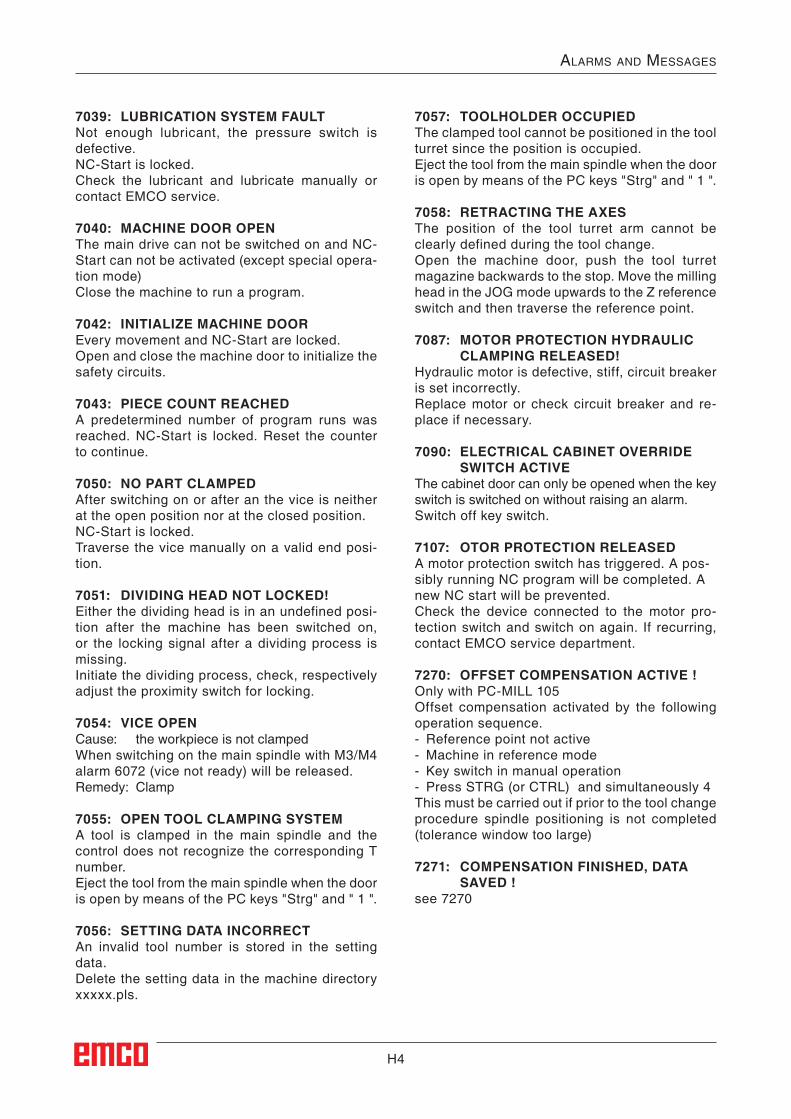
H4
AlArms And messAges
7039: LUBRICATION SYSTEM FAULTNot enough lubricant, the pressure switch is defective.NC-Start is locked.Check the lubricant and lubricate manually or contact EMCO service.
7040: MACHINE DOOR OPENThe main drive can not be switched on and NC-Start can not be activated (except special opera-tion mode)Close the machine to run a program.
7042: INITIALIZE MACHINE DOOREvery movement and NC-Start are locked.Open and close the machine door to initialize the safety circuits.
7043: PIECE COUNT REACHEDA predetermined number of program runs was reached. NC-Start is locked. Reset the counter to continue.
7050: NO PART CLAMPEDAfter switching on or after an the vice is neither at the open position nor at the closed position.NC-Start is locked.Traverse the vice manually on a valid end posi-tion.
7051: DIVIDING HEAD NOT LOCKED!Either the dividing head is in an undefined posi-tion after the machine has been switched on, or the locking signal after a dividing process is missing.Initiate the dividing process, check, respectively adjust the proximity switch for locking.
7054: VICE OPENCause: the workpiece is not clampedWhen switching on the main spindle with M3/M4 alarm 6072 (vice not ready) will be released.Remedy: Clamp
7055: OPEN TOOL CLAMPING SYSTEMA tool is clamped in the main spindle and the control does not recognize the corresponding T number.Eject the tool from the main spindle when the door is open by means of the PC keys "Strg" and " 1 ".
7056: SETTING DATA INCORRECTAn invalid tool number is stored in the setting data.Delete the setting data in the machine directory xxxxx.pls.
7057: TOOLHOLDER OCCUPIEDThe clamped tool cannot be positioned in the tool turret since the position is occupied.Eject the tool from the main spindle when the door is open by means of the PC keys "Strg" and " 1 ".
7058: RETRACTING THE AXESThe position of the tool turret arm cannot be clearly defined during the tool change.Open the machine door, push the tool turret magazine backwards to the stop. Move the milling head in the JOG mode upwards to the Z reference switch and then traverse the reference point.
7087: MOTOR PROTECTION HYDRAULIC CLAMPING RELEASED!
Hydraulic motor is defective, stiff, circuit breaker is set incorrectly.Replace motor or check circuit breaker and re-place if necessary.
7090: ELECTRICAL CABINET OVERRIDE SWITCH ACTIVE
The cabinet door can only be opened when the key switch is switched on without raising an alarm.Switch off key switch.
7107: OTOR PROTECTION RELEASEDA motor protection switch has triggered. A pos-sibly running NC program will be completed. A new NC start will be prevented.Check the device connected to the motor pro-tection switch and switch on again. If recurring, contact EMCO service department.
7270: OFFSET COMPENSATION ACTIVE !Only with PC-MILL 105Offset compensation activated by the following operation sequence.- Reference point not active- Machine in reference mode- Key switch in manual operation- Press STRG (or CTRL) and simultaneously 4This must be carried out if prior to the tool change procedure spindle positioning is not completed (tolerance window too large)
7271: COMPENSATION FINISHED, DATA SAVED !
see 7270

H5
AlArms And messAges
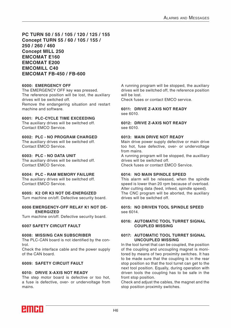
H6
AlArms And messAges
6000: EMERGENCY OFFThe EMERGENCY OFF key was pressed.The reference position will be lost, the auxiliary drives will be switched off.Remove the endangering situation and restart machine and software.
6001: PLC-CYCLE TIME EXCEEDINGThe auxiliary drives will be switched off.Contact EMCO Service.
6002: PLC - NO PROGRAM CHARGEDThe auxiliary drives will be switched off.Contact EMCO Service.
6003: PLC - NO DATA UNITThe auxiliary drives will be switched off.Contact EMCO Service.
6004: PLC - RAM MEMORY FAILUREThe auxiliary drives will be switched off.Contact EMCO Service.
6005: K2 OR K3 NOT DE-ENERGIZEDTurn machine on/off. Defective security board.
6006 EMERGENCY-OFF RELAY K1 NOT DE-ENERGIZED
Turn machine on/off. Defective security board.
6007 SAFETY CIRCUIT FAULT
6008: MISSING CAN SUBSCRIBERThe PLC-CAN board is not identified by the con-trol.Check the interface cable and the power supply of the CAN board.
6009: SAFETY CIRCUIT FAULT
6010: DRIVE X-AXIS NOT READYThe step motor board is defective or too hot, a fuse is defective, over- or undervoltage from mains.
A running program will be stopped, the auxiliary drives will be switched off, the reference position will be lost.Check fuses or contact EMCO service.
6011: DRIVE Z-AXIS NOT READYsee 6010.
6012: DRIVE Z-AXIS NOT READYsee 6010.
6013: MAIN DRIVE NOT READYMain drive power supply defective or main drive too hot, fuse defective, over- or undervoltage from mains.A running program will be stopped, the auxilliary drives will be switched off.Check fuses or contact EMCO Service.
6014: NO MAIN SPINDLE SPEEDThis alarm will be released, when the spindle speed is lower than 20 rpm because of overload.Alter cutting data (feed, infeed, spindle speed).The CNC program will be aborted, the auxiliary drives will be switched off.
6015: NO DRIVEN TOOL SPINDLE SPEEDsee 6014.
6016: AUTOMATIC TOOL TURRET SIGNAL COUPLED MISSING
6017: AUTOMATIC TOOL TURRET SIGNAL UNCOUPLED MISSING
In the tool turret that can be coupled, the position of the coupling and uncoupling magnet is moni-tored by means of two proximity switches. It has to be made sure that the coupling is in the rear stop position so that the tool turret can get to the next tool position. Equally, during operation with driven tools the coupling has to be safe in the front stop position.Check and adjust the cables, the magnet and the stop position proximity switches.
PC TURN 50 / 55 / 105 / 120 / 125 / 155Concept TURN 55 / 60 / 105 / 155 / 250 / 260 / 460Concept MILL 250EMCOMAT E160EMCOMAT E200EMCOMILL C40EMCOMAT FB-450 / FB-600
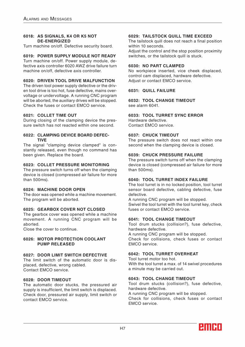
H7
AlArms And messAges
6018: AS SIGNALS, K4 OR K5 NOT DE-ENERGIZED
Turn machine on/off. Defective security board.
6019: POWER SUPPLY MODULE NOT READY Turn machine on/off. Power supply module, de-fective axis controller 6020 AWZ drive failure turn machine on/off, defective axis controller.
6020: DRIVEN TOOL DRIVE MALFUNCTIONThe driven tool power supply defective or the driv-en tool drive is too hot, fuse defective, mains over-voltage or undervoltage. A running CNC program will be aborted, the auxiliary drives will be stopped. Check the fuses or contact EMCO service.
6021: COLLET TIME OUTDuring closing of the clamping device the pres-sure switch has not reacted within one second.
6022: CLAMPING DEVICE BOARD DEFEC-TIVE
The signal "clamping device clamped" is con-stantly released, even though no command has been given. Replace the board.
6023: COLLET PRESSURE MONITORINGThe pressure switch turns off when the clamping device is closed (compressed air failure for more than 500ms).
6024: MACHINE DOOR OPENThe door was opened while a machine movement. The program will be aborted.
6025: GEARBOX COVER NOT CLOSEDThe gearbox cover was opened while a machine movement. A running CNC program will be aborted.Close the cover to continue.
6026: MOTOR PROTECTION COOLANT PUMP RELEASED
6027: DOOR LIMIT SWITCH DEFECTIVEThe limit switch of the automatic door is dis-placed, defective, wrong cabled.Contact EMCO service.
6028: DOOR TIMEOUTThe automatic door stucks, the pressured air supply is insufficient, the limit switch is displaced.Check door, pressured air supply, limit switch or contact EMCO service.
6029: TAILSTOCK QUILL TIME EXCEEDThe tailstock quill does not reach a final position within 10 seconds.Adjust the control and the stop position proximity switches, or the tailstock quill is stuck.
6030: NO PART CLAMPEDNo workpiece inserted, vice cheek displaced, control cam displaced, hardware defective.Adjust or contact EMCO service.
6031: QUILL FAILURE
6032: TOOL CHANGE TIMEOUTsee alarm 6041.
6033: TOOL TURRET SYNC ERRORHardware defective.Contact EMCO service.
6037: CHUCK TIMEOUTThe pressure switch does not react within one second when the clamping device is closed.
6039: CHUCK PRESSURE FAILUREThe pressure switch turns off when the clamping device is closed (compressed air failure for more than 500ms).
6040: TOOL TURRET INDEX FAILUREThe tool turret is in no locked position, tool turret sensor board defective, cabling defective, fuse defective.A running CNC program will be stopped.Swivel the tool turret with the tool turret key, check fuses or contact EMCO service.
6041: TOOL CHANGE TIMEOUTTool drum stucks (collision?), fuse defective, hardware defective.A running CNC program will be stopped.Check for collisions, check fuses or contact EMCO service.
6042: TOOL TURRET OVERHEATTool turret motor too hot.With the tool turret a max. of 14 swivel procedures a minute may be carried out.
6043: TOOL CHANGE TIMEOUTTool drum stucks (collision?), fuse defective, hardware defective.A running CNC program will be stopped.Check for collisions, check fuses or contact EMCO service.
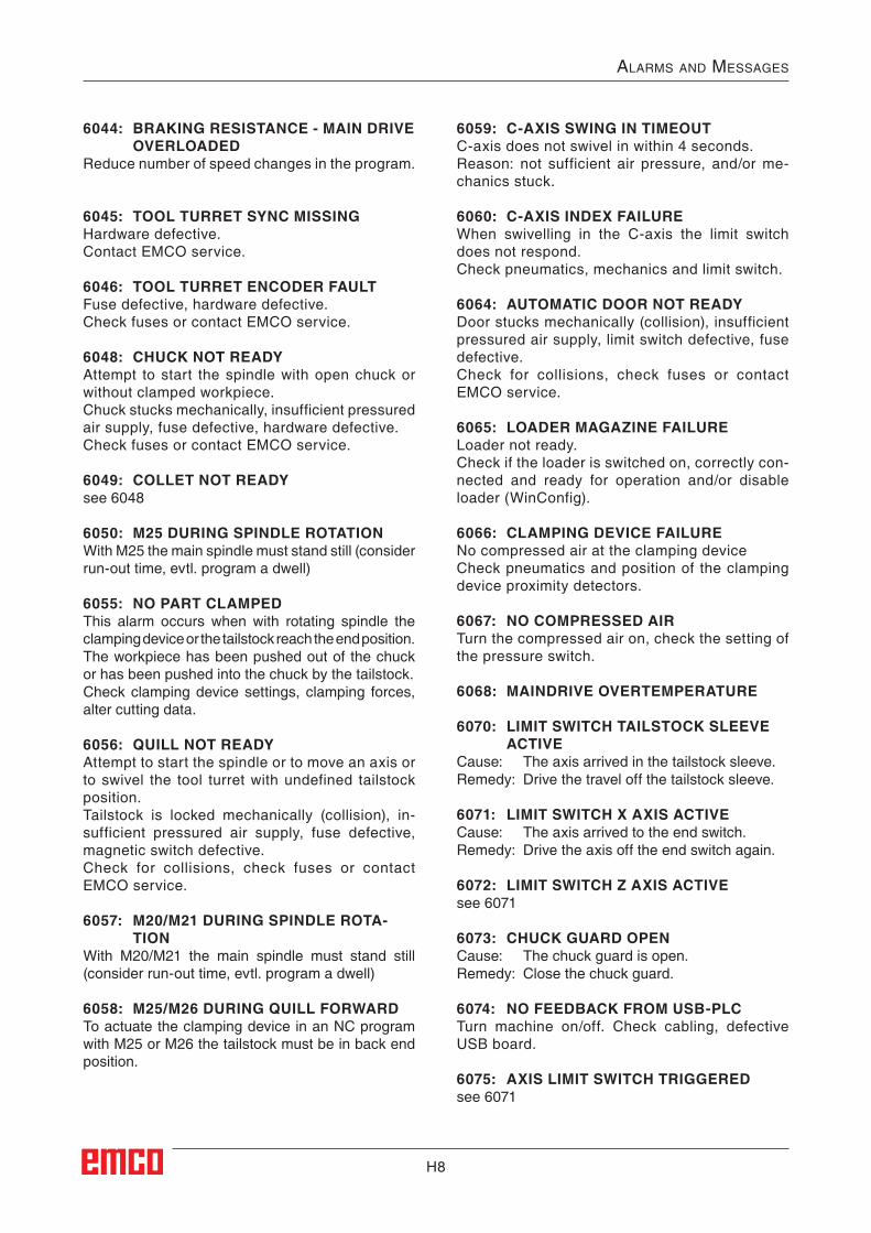
H8
AlArms And messAges
6044: BRAKING RESISTANCE - MAIN DRIVE OVERLOADED
Reduce number of speed changes in the program.
6045: TOOL TURRET SYNC MISSINGHardware defective.Contact EMCO service.
6046: TOOL TURRET ENCODER FAULTFuse defective, hardware defective.Check fuses or contact EMCO service.
6048: CHUCK NOT READYAttempt to start the spindle with open chuck or without clamped workpiece.Chuck stucks mechanically, insufficient pressured air supply, fuse defective, hardware defective.Check fuses or contact EMCO service.
6049: COLLET NOT READYsee 6048
6050: M25 DURING SPINDLE ROTATIONWith M25 the main spindle must stand still (consider run-out time, evtl. program a dwell)
6055: NO PART CLAMPEDThis alarm occurs when with rotating spindle the clamping device or the tailstock reach the end position.The workpiece has been pushed out of the chuck or has been pushed into the chuck by the tailstock.Check clamping device settings, clamping forces, alter cutting data.
6056: QUILL NOT READYAttempt to start the spindle or to move an axis or to swivel the tool turret with undefined tailstock position.Tailstock is locked mechanically (collision), in-sufficient pressured air supply, fuse defective, magnetic switch defective.Check for collisions, check fuses or contact EMCO service.
6057: M20/M21 DURING SPINDLE ROTA-TION
With M20/M21 the main spindle must stand still (consider run-out time, evtl. program a dwell)
6058: M25/M26 DURING QUILL FORWARDTo actuate the clamping device in an NC program with M25 or M26 the tailstock must be in back end position.
6059: C-AXIS SWING IN TIMEOUTC-axis does not swivel in within 4 seconds.Reason: not sufficient air pressure, and/or me-chanics stuck.
6060: C-AXIS INDEX FAILUREWhen swivelling in the C-axis the limit switch does not respond.Check pneumatics, mechanics and limit switch.
6064: AUTOMATIC DOOR NOT READYDoor stucks mechanically (collision), insufficient pressured air supply, limit switch defective, fuse defective.Check for collisions, check fuses or contact EMCO service.
6065: LOADER MAGAZINE FAILURELoader not ready.Check if the loader is switched on, correctly con-nected and ready for operation and/or disable loader (WinConfig).
6066: CLAMPING DEVICE FAILURENo compressed air at the clamping deviceCheck pneumatics and position of the clamping device proximity detectors.
6067: NO COMPRESSED AIRTurn the compressed air on, check the setting of the pressure switch.
6068: MAINDRIVE OVERTEMPERATURE
6070: LIMIT SWITCH TAILSTOCK SLEEVE ACTIVE
Cause: The axis arrived in the tailstock sleeve.Remedy: Drive the travel off the tailstock sleeve.
6071: LIMIT SWITCH X AXIS ACTIVECause: The axis arrived to the end switch.Remedy: Drive the axis off the end switch again.
6072: LIMIT SWITCH Z AXIS ACTIVEsee 6071
6073: CHUCK GUARD OPENCause: The chuck guard is open. Remedy: Close the chuck guard.
6074: NO FEEDBACK FROM USB-PLCTurn machine on/off. Check cabling, defective USB board.
6075: AXIS LIMIT SWITCH TRIGGEREDsee 6071
H9
AlArms And messAges
6076: DRIVE Y-AXIS NOT READYsee 6010
6077 VICE NOT READYCause: Loss of pressure in clamping system.Remedy: Check pressurised air and air ducts.
6078 MOTOR PROTECTION TOOL MAGA-ZINE RELEASED
Cause: Swing intervals are too short.Remedy: Raise swing intervals.
6079 MOTOR PROTECTION TOOL CHANG-ER RELEASED
see 6068
6080 PRESSURE SWITCH FOR TANI MISS-ING
Cause: The pressure switch fails to active when the clamping closes. No pressurised air or mechanical problem.
Remedy: Check pressurised air.
6081 CLAMPING FOR TANI NOT OPENsee 6080
6082 FAULT AS/SIGNALCause: Active Safety-Signal X/Y-controller is faulty.Remedy: Delete alarm using the RESET key and/
or switch the machine on/off. If this error reoccurs, contact EMCO.
6083 FAULT AS/SIGNALCause: Active Safety-Signal main spindle/Z-
controller is faulty.Remedy: Delete alarm using the RESET key and/
or switch the machine on/off. If this error reoccurs, contact EMCO.
6084 FAULT AS/SIGNAL UE-MODULCause: Active Safety-Signal Uncontrolled power
supply module is faulty.Remedy: Delete alarm using the RESET key and/
or switch the machine on/off. If this error reoccurs, contact EMCO.
6085 N=0 RELAY NOT DE-ENERGIZEDCause: Rotation zero relay did not drop.Remedy: Delete alarm using the RESET key and/
or switch the machine on/off. If this error reoccurs, contact EMCO (replace relay).
6086 DIFFERENT DOOR-SIGNALS FROM USBPLC AND ACC-PLC
Cause: ACC-PLC and USBSPS receive different door status reports.
Remedy: Delete alarm using the RESET key. If this error reoccurs, contact EMCO.
6087 DRIVE A-AXIS NOT READYsee 6010
6088 PROTECT SWITCH DOOR CONTROL UNIT RELEASED
Cause: Door drive overload.Remedy: Cancel alarm with RESET button or switch
machine on/off. If the problem occurs sev-eral times, contact EMCO (replace motor, drive).
6089 DRIVE B-AXIS NOT READYsee 6010
6090 CHIP CONVEYOR CONTACTOR NOT DE-ENERGIZED
Cause: Chip conveyor guard not down.Remedy: Cancel alarm with RESET button or switch
machine on/off. If the problem occurs sev-eral times, contact EMCO (replace guard).
6091 AUTOMATIC DOOR CONTACTOR NOT DE-ENERGIZED
Cause: Automatic door guard not down.Remedy: Cancel alarm with RESET button or switch
machine on/off. If the problem occurs sev-eral times, contact EMCO (replace guard).
6092 EMERGENCY-OFF EXTERNAL
6093 FAULT AS/SIGNAL A-AXISCause: Active Safety-Signal A control element
faulty.Remedy: Cancel alarm with RESET button or switch
machine on/off. If the problem occurs several times, contact EMCO.
6095 OVERHEATING IN THE SWITCHGEAR CABINET
Cause: Temperature monitoring responded.Remedy: Check switchgear cabinet filter and fan,
raise triggering temperature, switch ma-chine on and off.
6096 SWITCHGEAR CABINET DOOR OPENCause: Switchgear cabinet door opened without
key switch release.Remedy: Close switchgear cabinet door, switch
machine off and on.
H10
AlArms And messAges
6097 EMERGENCY-OFF TEST REQUIREDCause: Functional test of Emergency off.Remedy: Press EMERGENCY-OFF button on the
control panel and unlock again. Press Rest-button to acknowledge the emergency stop state.
6098 FLOAT SWITCH HYDRAULIC MISSINGEffect: Auxiliary units are switched off.Meaning: The hydraulic float switch has released.Remedy: Refill hydraulic oil.
6099 PROX. SWITCH SPINDLE-BRAKE 1 MISSING
Effect: Feed stop, Read in lockMeaning: M10 Spindle brake on Inductive proximity
switch stays 0. M11 Spindle brake off Inductive proximity
switch stays 1.Remedy: Check inductive proximity switch, check
magnetiv valve spindle brake.
6100 LOW PRESSURE QUILLEffect: Auxiliary units are switched off.Meaning: At the moment of a spindle start command
the tailstock pressure was not built up or the pressure dropped while spindle run.
Remedy: Check clamping device pressure and pres-sure switch.
Check program.
6101 QUILL -B3 OR -B4 MISSINGEffect: Feed stop, Read in lockMeaning: The magnetic valve for the movement of
the quill was activated, but the switches –B3 and –B4 does not alter its status.
Remedy: Check switches, magnetic valves.
6102 QUILL POSITION ALARM (PART MOVED?)
Effect: Feed stop, Read in lockMeaning: The tailstock target position was overtrav-
elled in AUTOMATIC mode.Remedy: Check tailstock target position, check tech-
nology (clamping device pressure higher, tailstock pressure lower)
6103 QUILL NO BACKPOSITIONEffect: Feed stop, Read in lockMeaning: The magnetic valve for the tailstock was
activated, but the switch for "tailstock back" stays 0.
Remedy: Check magnetic valve, check switch.
6104 LOW PRESSURE CLAMPING EQUIPMENT 1
Effect: Auxiliary units are switched off.Meaning: At the moment of a spindle start command
the clamping pressure was not built up or the clamping pressure dropped while spindle run.
Remedy: Check clamping device pressure and pres-sure switch.
Check program.
6105 CLAMPING EQUIPMENT 1 NOT OPENEffect: Feed stop, Read in lockMeaning: The analogous proximity switch for clamp-
ing device 1 was not actuated.Remedy: Adjust inductive proximity switch (see
"Machine Description - chapter "C Pro-gramming and operation").
6106 CLAMPING EQUIPMENT 1 NOT CLOSEDEffect: Feed stop, Read in lockMeaning: The pressure switch for "clamping device
closed" does not switch.Remedy: Check pressure switch
6107 LIMIT SWITCH CLAMPING EQUIPMENT 1Effect: Auxiliary units are switched off.Remedy: Adjust clamping device (do not clamp in
end position of the clamping system - see "Machine Description, chapter C Program-ming and Operation").
6108 PARTS CATCHER FORWARD MISSINGEffect: Feed stop, Read in lockMeaning: The magnetic valve for "collection tray
forward/backward" was activated, but the switch for "collection tray forward/backward" does not alter its status.
Remedy: Check switches, magnetic valves.
6109 PARTS CATCHER ROTATE IN MISSINGEffect: Feed stop, Read in lockMeaning: The magnetic valve for "collection tray in/
out" was activated, but the switch for "col-lection tray in/out" does not alter its status.
Remedy: Check switch, magnetic valve.
6900 USBPLC not availableCause: USB communication with the safety board
could not be established.Remedy: Switch the machine off and on again.
Please contact the EMCO after-sales ser-vice in case the error occurs repeatedly.
H11
AlArms And messAges
6901 Error emergency-off relay USBPLCCause: USBPLC EMERGENCY-OFF relay error.Remedy: Switch the machine off and on again.
Please contact the EMCO after-sales ser-vice in case the error occurs repeatedly.
6902 Error standstill monitoring XCause: Unauthorized movement of the X axis in
the current operating condition.Remedy: Delete the alarm with the RESET button
and switch the machine off and on again. Please contact the EMCO after-sales ser-vice in case the error occurs repeatedly.
6903 Error standstill monitoring ZCause: Unauthorized movement of the Z axis in
the current operating condition.Remedy: Delete the alarm with the RESET button
and switch the machine off and on again. Please contact the EMCO after-sales ser-vice in case the error occurs repeatedly.
6904 Error alive circuit PLCCause: Error in the connection (Watchdog) of the
safety board with the PLC.Remedy: Delete the alarm with the RESET button and
switch the machine off and on again. Please contact the EMCO after-sales service in case the error occurs repeatedly.
6906 Error overspeed spindleCause: The main spindle speed exceeds the
maximum permissible value for the current operating condition.
Remedy: Delete the alarm with the RESET button and switch the machine off and on again. Please contact the EMCO after-sales service in case the error occurs repeatedly.
6907 Error enable pulses ER-moduleCause: ACC-PLC did not shutdown the input/
negative feeder-module.Remedy: Delete the alarm with the RESET button
and switch the machine off and on again. Please contact the EMCO after-sales ser-vice in case the error occurs repeatedly.
6908 Error standstill monitoring main driveCause: Unexpeced warm up of the main spindle
in the operating condition.Remedy: Delete the alarm with the RESET button
and switch the machine off and on again. Please contact the EMCO after-sales ser-vice in case the error occurs repeatedly.
6909 Error main drive enable without spindle start
Cause: The release of the control unit of the main spindle was given by the ACC-PLC without the spindle-start key being pressed.
Remedy: Delete the alarm with the RESET button and switch the machine off and on again. Please contact the EMCO after-sales ser-vice in case the error occurs repeatedly.
6910 Error standstill monitoring YCause: Unauthorized movement of the Y axis in
the current operating condition.Remedy: Delete the alarm with the RESET button
and switch the machine off and on again. Please contact the EMCO after-sales ser-vice in case the error occurs repeatedly.
6911 Error standstill axesCause: Unauthorized movement of the axis in the
current operating condition.Remedy: Delete the alarm with the RESET button
and switch the machine off and on again. Please contact the EMCO after-sales ser-vice in case the error occurs repeatedly.
6912 Error overspeed axisCause: The feed of the axes exceeds the maximum permissible value for the current op-erating condition.Remedy: Delete the alarm with the RESET button
and switch the machine off and on again. Please contact the EMCO after-sales ser-vice in case the error occurs repeatedly.
6913 Error overspeed XCause: The feed of the X axis exceeds the maxi-
mum permissible value for the current operating condition.
Remedy: Delete the alarm with the RESET button and switch the machine off and on again. Please contact the EMCO after-sales ser-vice in case the error occurs repeatedly.
6914 Error overspeed YCause: The feed of the Y axis exceeds the maxi-
mum permissible value for the current operating condition.
Remedy: Delete the alarm with the RESET button and switch the machine off and on again. Please contact the EMCO after-sales ser-vice in case the error occurs repeatedly.
H12
AlArms And messAges
6915 Error overspeed ZCause: The feed of the Y axis exceeds the maxi-
mum permissible value for the current operating condition.
Remedy: Delete the alarm with the RESET button and switch the machine off and on again. Please contact the EMCO after-sales ser-vice in case the error occurs repeatedly.
6916 ERROR: X-INDUCTIVE PROXIMITY SWITCH DEFECT
Cause: No signal is delivered by X axis Bero.Remedy: Delete alarm using the RESET key. If this
error reoccurs, contact EMCO.
6917 ERROR: Y-INDUCTIVE PROXIMITY SWITCH DEFECT
Cause: No signal is delivered by Y axis Bero.Remedy: Delete alarm using the RESET key. If this
error reoccurs, contact EMCO.
6918 ERROR: Z-INDUCTIVE PROXIMITY SWITCH DEFECT
Cause: No signal is delivered by Z axis Bero.Remedy: Delete alarm using the RESET key. If this
error reoccurs, contact EMCO.
6919 ERROR: SPINDLE-INDUCTIVE PROX-IMITY SWITCH DEFECT
Cause: No signal is delivered by main spindle Bero.Remedy: Delete alarm using the RESET key. If this
error reoccurs, contact EMCO.
6920 INVERSION OF X-DIRECTION TOO LONG "1"Cause: The change in direction of X axis was be-
ing sent to USBSPS for more than three seconds.
Remedy: Delete alarm using the RESET key. Avoid driving back and forth using the manual wheel. If this error reoccurs, contact EMCO.
6921 INVERSION OF Y-DIRECTION TOO LONG "1"Cause: The change in direction oY axis was be-
ing sent to USBSPS for more than three seconds.
Remedy: Delete alarm using the RESET key. Avoid driving back and forth using the manual wheel. If this error reoccurs, contact EMCO.
6922 INVERSION OF Z-DIRECTION TOO LONG "1"Cause: The change in direction of Z axis was be-
ing sent to USBSPS for more than three seconds.
Remedy: Delete alarm using the RESET key. Avoid driving back and forth using the manual wheel. If this error reoccurs, contact EMCO.
6923 DIFFERENT DOOR-SIGNALS FROM USBPLC AND ACC-PLC
Cause: ACC-PLC and USBSPS receive different door status reports.
Remedy: Delete alarm using the RESET key. If this error reoccurs, contact EMCO.
6924 ERROR ENABLE PULSES MAIN DRIVECause: The pulse release on the main spindle
control element was interrupted by the USBSPS, as the PLC did not shut it down in a timely fashion.
Remedy: Cancel alarm with RESET button. If the problem occurs several times, contact EMCO.
6925 GRID PROTECTION ERROR!Cause: Grid protection does not drop out in current
operating state, or does not engage.Remedy: Clear alarm with emergency off button
and restart the machine. Contact EMCO Customer Service if the error occurs on several occasions.
6926 MOTOR PROTECTION ERROR!Cause: Motor protection drops out in current op-
erating state.Remedy: Clear alarm with emergency off button
and restart the machine. Contact EMCO Customer Service if the error occurs on several occasions.
6927 EMERGENCY OFF ACTIVE ERROR!Cause: Emergency off button was pressed.Remedy: Restart the machine.
6928 TOOL CHANGER SHUTDOWN MONI-TORING ERROR
Cause: Unauthorised tool changer movement in the current operating state.
Remedy: Clear alarm with emergency off button and restart the machine. Contact EMCO Customer Service if the error occurs on several occasions.
6929 MACHINE DOOR CLOSING/LOCKING ERROR
Cause: State of the door lock not plausible or door closure unserviceable.
Remedy: Clear alarm with emergency off button and restart the machine. Contact EMCO Customer Service if the error occurs on several occasions.
H13
AlArms And messAges
6930 BEROS MAIN SPINDLE PLAUSIBILITY ERROR
Cause: Beros main spindle signal different.Remedy: Clear alarm with emergency off button
and restart the machine. Contact EMCO Customer Service if the error occurs on several occasions.
6931 MAIN DRIVE QUICK STOP FUNCTION PLAUSIBILITY ERROR
Cause: Main drive actuator does not confirm the quick stop function in the current operating state.
Remedy: Clear alarm with emergency off button and restart the machine. Contact EMCO Customer Service if the error occurs on several occasions.
6999 USB-EXTENSION FOR ROBOTIK NOT AVAILABLE
Cause: The USB extension for robotics cannot be addressed by ACC.
Remedy: Contact EMCO.
7000: INVALID TOOL NUMBER PRO-GRAMMED
The tool position was programmed larger than 8.The CNC program will be stopped.Interrupt program with RESET and correct the program.
7007: FEED HOLDIn the robotic mode a HIGH signal is at input E3.7. Feed Stop is active until a low signal is at E3.7.
7016: SWITCH ON AUXILIARY DRIVESThe auxiliary drives are off. Press the AUX ON key for at least 0.5 sec. (to avoid accidentally switching on) to switch on the auxiliary drives (also a lubricating pulse will be released).
7017: REFERENCE MACHINEApproach the reference point.When the reference point is not active, manual movements are possible only with key switch at position "setting operation".
7018: TURN KEY SWITCHWith NC-Start the key switch was in position "set-ting operation".NC-Start is locked.Turn the key switch in the position "automatic" to run a program.
7019: PNEUMATIC LUBRICATION MONI-TORING!
Refill pneumatic oil
7020: SPECIAL OPERATION MODE ACTIVESpecial operation mode: The machine door is opened, the auxiliary drives are switched on, the key switch is in position "setting operation" and the consent key is pressed.Manual traversing the axes is possible with open door. Swivelling the tool turret is possible with open door. Running a CNC program is possible only with standing spindle (DRYRUN) and SIN-GLE block operation.For safety: If the consent key is pressed for more than 40 sec. the function of this key is interrupted, the consent key must be released and pressed again.
7021: TOOL TURRET NOT LOCKEDThe tool turret operating was interrupted.NC start and spindle start are locked. Press the tool turret key in the RESET status of the control.
7022: COLLECTION DEVICE MONITORINGTime exceed of the swivelling movement.Check the pneumatics, respectively whether the mechanical system is jammed (possibly a work-piece is jammed).
7023: ADJUST PRESSURE SWITCH !During opening and closing of the clamping de-vice the pressure switch has to turn off and on once.Adjust the pressure switch. This alarm does not exist any more for versions starting with PLC 3.10.
7024: ADJUST CLAMPING DEVICE PROXIM-ITY SWITCH !
When the clamping device is open and the posi-tion stop control is active, the respective proximity switch has to feed back that the clamping device is "Open".Check and adjust the clamping device proximity switch, check the cables.
7025 WAITING TIME MAIN DRIVE !The LENZE frequency converter has to be sepa-rated from the mains supply for at least 20 sec-onds before you are allowed to switch it on again. This message will appear when the door is quickly openend/ closed (under 20 seconds).
7026 PROTECTION MAIN MOTOR FAN RE-LEASED!
H14
AlArms And messAges
7038: LUBRICATION SYSTEM FAULTThe pressure switch is defective or gagged.NC-Start is locked. This alarm can be reset only by switching off and on the machine.Contact EMCO service.
7039: LUBRICATION SYSTEM FAULTNot enough lubricant, the pressure switch is defective.NC-Start is locked.Check the lubricant and lubricate manually or contact EMCO service.
7040: MACHINE DOOR OPENThe main drive can not be switched on and NC-Start can not be activated (except special opera-tion mode)Close the machine to run a program.
7041: GEARBOX COVER OPENThe main spindle cannot be switched on and NC start cannot be activated.Close the gearbox cover in order to start a CNC program.
7042: INITIALIZE MACHINE DOOREvery movement and NC-Start are locked.Open and close the machine door to initialize the safety circuits.
7043: PIECE COUNT REACHEDA predetermined number of program runs was reached. NC-Start is locked. Reset the counter to continue.
7048: CHUCK OPENThis message shows that the chuck is open. It will disappear if a workpiece will be clamped.
7049: CHUCK - NO PART CLAMPEDNo part is clamped, the spindle can not be switched on.
7050: COLLET OPENThis message shows that the collet is open. It will disappear if a workpiece will be clamped.
7051: COLLET - NO PART CLAMPEDNo part is clamped, the spindle can not be switched on.
7052: QUILL IN UNDEFINED POSITIONThe tailstock is in no defined position.All axis movements, the spindle and the tool tur-ret are locked.Drive the tailstock in back end position or clamp a workpiece with the tailstock.
7053: QUILL - NO PART CLAMPEDThe tailstock reached the front end position. Trav-erse the tailstock back to the back end position to continue.
7054: NO PART CLAMPEDNo part clamped, switch-on of the spindle is locked.
7055: CLAMPING DEVICE OPENThis message indicates that the clamping device is not in clamping state. It disappears as soon as a part is clamped.
7060 RETRACT SLEEVE LIMIT SWITCH !The axis arrived in the tailstock sleeve. Drive the travel off the tailstock sleeve.
7061 RETRACT X AXIS LIMIT SWITCH !The axis arrived to the end switch. Drive the axis off the end switch again.
7062 RETRACT Z AXIS LIMIT SWITCH !see 7061
7063 OIL LEVEL CENTRAL LUBRICATION !Low oil level in central lubrication. Refill oil as per maintenance instructions to the machine.
7064 CHUCK GUARD OPEN !The chuck guard is open. Close the chuck guard.
7065 MOTOR PROTECTION COOLANT PUMP RELEASED !
Overheated coolant pump. Check the coolant pump for ease of motion and presence of dirt. Ensure sufficient amount of coolant fluid in the coolant facility.
7066 CONFIRM TOOL !To confirm the tool change, press T after the change has been completed.
7067 MANUAL OPERATING MODEThe Special Operation key switch is in the Set position (manual).
7068 X AXIS HANDWHEEL ACTIVEThe safety wheel is locked for manual travel movement. The safety wheel locking is monitored by contactless switches. With the manual wheel locked, the axis feed cannot be switched on. For automatic processing of a program, the manual wheel must be released again.
7069 Y AXIS HANDWHEEL ACTIVEsee 7068
H15
AlArms And messAges
7070 Z AXIS HANDWHEEL ACTIVEsee 7068
7071 VERTICAL TOOL CHANGEThe sheath for manual clamping of the tool holder is monitored by a switch. The switch reports a unaccepted socket wrench or a sheath which was left open. Remove the socket wrench after clamping the tool and close the sheath.
7072 HORIZONTAL TOOL CHANGEThe turning knob for manual tool clamping on the horizontal spindle is monitored by a switch. The switch reports a tightened turning knob. The spindle gets locked. Release the turning knob after clamping the tool.
7073 RETRACT Y AXIS LIMIT SWITCH !see 7061
7074 CHANGE TOOLClamp programmed tool.
7076: SWIVEL UNIT VOR MILLING HEAD UNLOCKED
The milling head is not fully swung. Fix the mill-ing head mechanically (the end switch must be pushed).
7077: ADJUST TOOL TURRETNo valid machine data for tool change are avail-able. Contact EMCO.
7078: POCKET NOT IN HOME POSITIONCancel during tool change. Swing back tool re-cessed in setup operation.
7079: TOOL ARM NOT IN HOME POSITIONsee 7079
7080: INCORRECT TOOL CLAMPED !The tool cone lies beyond tolerance. The clamped tool is twisted by 180°. Bero tool clamping is dis-placed. Check the tool and clamp it again. If this problem occurs with more tools, contact EMCO.
7082: MOTOR PROTECTION CHIP CONVEY-OR RELEASED
The scrap belt is overloaded. Check the conveyor belt for ease of motion and remove jammed scrap.
7083: MAGAZINE IS ACTIVE !A tool has been removed from the non-chaotic tool administration from the main spindle. Fill the tool drum.
7084: VICE OPEN !The vice is not clamped. Clamp the vice.
7085 ROUNDAXIS A MOVE TO 0 DEGRE !Cause: The MOC only shuts down if the A Round
axis is at 0°. When 4.5. is present, a round axis must
be made each time before the machine is switched off.
Remedy: Move round axis to 0°.
7088 SWITCHGEAR CABINET OVERHEAT-ING
Cause: Temperature monitoring responded.Remedy: Check switchgear cabinet filter and fan,
raise trigger temperature.
7089 SWITCHGEAR CABINET DOOR OPENCause: Switchgear cabinet door open.Remedy: Close switchgear cabinet door.
7091 WAIT FOR USB-I2C SPSCause: Communication with the USB-I2C PLC
could not be established.Remedy: If the message does not self-extinguish,
switch off and on the machine. Please contact EMCO service when the message occurs permanently even after power off.
7092 TEST STOP ACTIVECause: Safety test for monitoring the safety func-
tions is active.Remedy: Wait until the safety test is finished.
7093 SET REFERENCE POINTCause: The reference point acknowledge mode
was activated by the operator.
7094 SET X-REFERENCE POINTCause: The reference value of the X axis was
adopted to the acc.esd file.
7095 SET Y-REFERENCE POINTCause: The reference value of the Y axis was
adopted to the acc.esd file.
7096 SET Z-REFERENCE POINTCause: The reference value of the Z axis was
adopted to the acc.esd file.
7097 FEED OVERRIDE 0Cause: The override switch (feed control) was set
by the operator on 0%
H16
AlArms And messAges
7098 SPINDLE-BRAKE 1 ACTIVEEffect: spindle stop.
7099 QUILL DRIVES FORWARDEffect: Feed stop, Read in lockMeaning: M21 was programmed pressure switch
"tailstock in front position" is not yet 1.Remedy: Disappears with pressure switch front
position.
7100 QUILL DRIVES BACKWARDEffect: Feed stop, Read in lockMeaning: M20 was programmed limit switch "tail-
stock back" is not yet 1Remedy: Disappears with limit switch "back position".
7101 REFERENCE POINT TOOL TURRET MISSING
Effect: Feed stop, Read in lockMeaning: At NC start the tool turret is not referenced.Remedy: Reference tool turret in JOG mode with
tool turret key.
7102 TOOL TURRET IN MOTIONEffect: Tool turret swivels to the programmed
position.
7103 LIMIT-SWITCH CLAMPING EQUIP-MENT 1
Effect: Locking of NC start and main drive start, spindle stop S1
Meaning: The pick-up for the analouge value detects the clamping position as end position.
Remedy: Change clamping range of the clamping device (see "Machine Description - chapter C Programming and Operation").
7104 QUILL IN INTERMEDIATE POSITIONEffect: Feed hold / read in stop.
7105 SET AWZ REFERENCE POINTEffect: The reference value of the AWZ motor was
transferred to the acc.msd file.
7900 INITIALIZE EMERGENCY OFF!Cause: The emergency off button must be initial-
ized.Remedy: Press and then release emergency off
button.
7901 INITIALIZE MACHINE DOORS!Cause: The machine doors must be initialized.Remedy: Open the machine doors and close them
again.
7906 SET A-REFERENCE POINT Cause: The reference value of the A axis was
adopted to the acc.esd file.
H17
AlArms And messAges
Inputunit alarms 1700 - 1899These alarms and messages are raised by the control keyboard.
1701 Error in RS232Cause: Serial port settings are invalid or the con-
nection to the serial keyboard were inter-rupted.
Remedy: Check the settings of the serial interface and/or turn keyboard off/on and check the control cable connection.
1703 Ext. keyboard not availableCause: Connection with the external keyboard can
not be made.Remedy: Check the settings of the external keyboard
and/or check the cable connection.
1704 Ext. keyboard: checksum errorCause: Error in the transmission.Remedy: The connection to the keyboard is auto-
matically restored. If this fails, turn off or on the keyboard.
1705 Ext. keyboard: general errorCause: The attached keyboard reported an error.Remedy: Plug the keyboard off and on again.Con-
tact EMCO Customer Service if the error occurs on several occasions.
1706 General USB errorCause: Error in the USB communication.Remedy: Plug the keyboard off and on again.Con-
tact EMCO Customer Service if the error occurs on several occasions
1707 Ext. Keyboard: no LEDsCause: Fehlerhaftes LED-Kommando wurde an
die Tastatur gesandt.Remedy: EMCO-Service kontaktieren.
1708 Ext. Keyboard: unknown commandCause: Unknown command was sent to the key-
board.Remedy: Contact EMCO Customer Service
1710 Installation of Easy2control is damaged!Cause: Incorrect installation of Easy2controlRemedy: Reinstall software and/or contact EMCO
Customer Service
1711 Initialization of Easy2Control failed!Cause: Configuration file onscreen.ini for Easy-
2control is missing.Remedy: Reinstall software and/or contact EMCO
Customer Service.
1712 USB-Dongle for Easy2control could not be found!
Cause: USB-Dongle for Easy2control is not con-nected. Easy2control is displayed but can not be operated.
Remedy: Connect USB-Dongle for Easy2control.
1801 Keytable not found!Cause: The file with the keytable couldn't be found.Remedy: Reinstall software and/or contact EMCO
Customer Service.
1802 Connection to keyboard lostCause: Connection to the serial keyboard was
interrupted.Remedy: Turn keyboard off/on and check the cable
connection.

H18
AlArms And messAges
H19
AlArms And messAges
8000 Fatal Error AC8100 Fatal init error ACCause: Internal errorRemedy: Restart software or reinstall when neces-
sary, report to EMCO, if repeatable.8101 Fatal init error ACsee 8101.8102 Fatal init error ACsee 8101.8103 Fatal init error ACsee 8101.8104 Fatal system error ACsee 8101.8105 Fatal init error ACsee 8101.8106 No PC-COM card foundCause: PC-COM board can not be accessed (ev.
not mounted).Remedy: Mount board, adjust other address with
jumper8107 PC-COM card not workingsee 8106.8108 Fatal error on PC-COM cardsee 8106.8109 Fatal error on PC-COM cardsee 8106.8110 PC-COM init message missingCause: Internal errorRemedy: Restart software or reinstall when neces-
sary, report to EMCO, if repeatable.8111 Wrong configuration of PC-COMsee 8110.8113 Invalid data (pccom.hex)see 8110.8114 Programming error on PC-COMsee 8110.8115 PC-COM packet acknowledge missingsee 8110.8116 PC-COM startup errorsee 8110.8117 Fatal init data error (pccom.hex)see 8110.8118 Fatal init error ACsee 8110, ev. insufficient RAM memory
8119 PC interrupt no. not validCause: The PC interrupt number can not be used.Remedy: Find out free interrupt number in the Win-
dows95 system control (allowed: 5,7,10, 11, 12, 3, 4 und 5) and enter this number in WinConfig.
8120 PC interrupt no. unmaskablesee 81198121 Invalid command to PC-COMCause: Internal error or defective cableRemedy: Check cables (screw it); Restart software or
reinstall when necessary, report to EMCO, if repeatable.
8122 Internal AC mailbox overrunCause: Internal errorRemedy: Restart software or reinstall when neces-
sary, report to EMCO, if repeatable.8123 Open error on record fileCause: Internal errorRemedy: Restart software or reinstall when neces-
sary, report to EMCO, if repeatable.8124 Write error on record fileCause: Internal errorRemedy: Restart software or reinstall when neces-
sary, report to EMCO, if repeatable.8125 Invalid memory for record bufferCause: Insufficient RAM, record time exceeding.Remedy: Restart software, ev. remove drivers etc.
to gain more RAM, reduce record time.8126 AC Interpolation overrunCause: Ev. insufficient computer performance.Remedy: Set a longer interrupt time in WinConfig.
This may result in poorer path accuracy.8127 Insufficient memoryCause: Insufficient RAMRemedy: Close other programs, restart software, ev.
remove drivers etc. to gain more RAM.8128 Invalid message to ACCause: Internal errorRemedy: Restart software or reinstall when neces-
sary, report to EMCO, if repeatable.8129 Invalid MSD data - axisconfig.see 8128.8130 Internal init error ACsee 8128.8130 Internal init error ACsee 8128.
Axis Controller Alarms 8000 - 9000, 22000 - 23000, 200000 - 300000
H20
AlArms And messAges
8132 Axis accessed by multiple channelssee 8128.8133 Insufficient NC block memory ACsee 8128.8134 Too much center points programmedsee 8128.8135 No centerpoint programmedsee 8128.8136 Circle radius too smallsee 8128.8137 Invalid for Helix specifiedCause: Wrong axis for helix. The combination of
linear and circular axes does not match.Remedy: Program correction.8140 Maschine (ACIF) not respondingCause: Machine off or not connected.Remedy: Switch on machine or connect.8141 Internal PC-COM errorCause: Internal errorRemedy: Restart software or reinstall when neces-
sary, report to EMCO, if repeatable.8142 ACIF Program errorCause: Internal errorRemedy: Restart software or reinstall when neces-
sary, report to EMCO, if repeatable.8143 ACIF packet acknowledge missingsee 8142.8144 ACIF startup errorsee 8142.8145 Fatal init data error (acif.hex)see 8142.8146 Multiple request for axissee 8142.8147 Invalid PC-COM state (DPRAM)see 8142.8148 Invalid PC-COM command (CNo)see 8142.8149 Invalid PC-COM command (Len)see 8142.8150 Fatal ACIF errorsee 8142.8151 AC Init Error (missing RPG file)see 8142.8152 AC Init Error (RPG file format)see 8142.8153 FPGA program timeout on ACIFsee 8142.8154 Invalid Command to PC-COMsee 8142.8155 Invalid FPGA packet acknowledgesee 8142 or hardware error on ACIF board (contact EMCO Service).
8156 Sync within 1.5 revol. not foundsee 8142 or Bero hardware error (contact EMCO Service).8157 Data record donesee 8142.8158 Bero width too large (referencing)see 8142 or Bero hardware error (contact EMCO Service).8159 Function not implementedBedeutung: In normal operation this function can
not be executed8160 Axis synchronization lost axis 3..7Cause: Axis spins or slide is locked, axis synchro-
nisation was lostRemedy: Approach reference point8161 X-Axis synchronization lostStep loss of the step motor. Causes:- Axis mechanically blocked- Axis belt defective- Distance of proximity detector too large
(>0,3mm) or proximity detector defective- Step motor defective8162 Y-Axis synchronization lostsee 81618163 Z-Axis synchronization lostsee 81618164 Software limit switch max axis 3..7Cause: Axis is at traverse area endRemedy: Retract axis8168 Software limit overtravel axis 3..7Cause: Axis is at traverse area endRemedy: Retract axis8172 Communication error to machineCause: Internal errorRemedy: Restart software or reinstall when neces-
sary, report to EMCO, if repeatable. Check connection PC - machine, eventu-
ally eliminate distortion sources.8173 INC while NC program is runningRemedy: Stop the program with NC stop or with
Reset. Traverse the axis.8174 INC not allowedCause: At the moment the axis is in motion.Remedy: Wait until the axis stops and then traverse
the axis.8175 MSD file could not be openedCause: Internal errorRemedy: Restart software oder bei Bedarf neu in-
stallieren, report to EMCO, if repeatable.8176 PLS file could not be openedsee 8175.
H21
AlArms And messAges
8177 PLS file could not be accessedsee 8175.8178 PLS file could not be writtensee 8175.8179 ACS file could not be openedsee 8175.8180 ACS file could not be accessedsee 8175.8181 ACS file could not be writtensee 8175.8183 Gear too highCause: The selected gear step is not allowed at
the machine. 8184 Invalid interpolaton command8185 Forbidden MSD data changesee 8175.8186 MSD file could not be openedsee 8175.8187 PLC program errorsee 8175.8188 Gear command invalidsee 8175.8189 Invalid channel assignementsee 8175.8190 Invalid channel within messagesee 8175.8191 Invalid jog feed unitCause: The machine does not support the rotation
feed in the JOG operating mode.Remedy: Order a software update from EMCO.8192 Invalid axis in commandsee 8175.8193 Fatal PLC errorsee 8175.8194 Thread without lengthCause: The programmed target coordinates are
identical to the starting coordinates.Remedy: Correct the target coordinates.8195 No thread slope in leading axisRemedy: Program thread pitch8196 Too manny axis for threadRemedy: Program max. 2 axes for thread.8197 Thread not long enoughCause: Thread length too short. With transition from one thread to the other
the length of the second thread must be sufficient to produce a correct thread.
Remedy: Longer second thread or replace it by a linear interpolation (G1).
8198 Internal error (to manny threads)see 8175.
8199 Internal error (thread state)Cause: Internal errorRemedy: Restart software or reinstall when neces-
sary, report to EMCO, if repeatable.8200 Thread without spindle onRemedy: Switch on spindle8201 Internal thread error (IPO)see 8199.8201 Internal thread error (IPO)see 8199.8203 Fatal AC error (0-ptr IPO)see 8199.8204 Fatal init error: PLC/IPO runningsee 8199.8205 PLC Runtime exceededCause: Insufficient computer performance8206 Invalid PLC M-group initialisationsee 8199.8207 Invalid PLC machine datasee 8199.8208 Invalid application messagesee 8199.8212 Rotation axis not allowedsee 8199.8213 Circle and rotation axis can't be inter-polated8214 Thread and rotation axis cant't be in-terpolated8215 Invalid statesee 8199.8216 No rotation axis for rotation axis switchsee 8199.8217 Axis type not valid!Cause: Switching during the rotary axis operating
mode when the spindle is running.Remedy: Stop the spindle and switch over to the
rotary axis operating mode.8218 Referencing round axis without select-ed round axis!see 8199.8219 Thread not allowed without spindle encoder!Cause: Thread cutting, respectively tapping is
only possible with spindles with encoders.8220 Buffer length exceeded in PC send message!see 8199.8221 Spindle release although axis is no spindle!see 8199.
H22
AlArms And messAges
8222 New master spindle is not validCause: The indicated master spindle is not valid
when switching over to the master spindle.Remedy: Correct the spindle number.8224 Invalid stop modesee 8199.8225 Invalid parameter for BC_MOVE_TO_IO!Cause: The machine is not configurated for touch
probes. A traversing movement with rotary axis is not allowed during touch probe operating mode.
Remedy: Remove the rotary axis movement from the traversing movement.
8226 Rotary axis switch not valid (MSD data)!Cause: The indicated spindle does not have a
rotary axis.8228 Rotary axis switch not allowed while axis move!Cause: The rotary axis has moved during switching
over to the spindle operating mode.Remedy: Stop the rotary axis before switching.8229 Spindle on not allowed while rotary axis is active!8230 Program start not allowed due to active spindle rotation axis!8231 Axis configuration (MSD) for TRANS-MIT not valid!Cause: Transmit is not possible at this machine.8232 Axis configuration (MSD) for TRACYL not valid!Cause: Tracyl is not possible at this machine.8233 Axis not available while TRANSMIT/TRACYL is active!Cause: Programming of the rotary axis is not al-
lowed during Transmit/ Tracyl.8234 Axis control grant removed by PLC while axis interpolates!Cause: Internal errorRemedy: Delete error with reset and inform EMCO.8235 Interpolation invalid while axis control grant is off by PLC!see 8234.8236 TRANSMIT/TRACYL activated while axis or spindle moves!see 8234.8237 Motion through pole in TRANSMIT!Cause: It is not allowed to move through the co-
ordinates X0 Y0 inTransmit.Remedy: Alter the traversing movement.
8238 Speed limit in TRANSMIT exceeded!Cause: The traversing movement gets too close to
the coordinates X0 Y0. In order to observe the programmed feed rate, the maximum speed of the rotary axis would have to be exceeded.
Remedy: Reduce the feed rate. Set the value of the C-axis feed limitation in WinConfig, machine data settings / general machine data/ to 0.2. Thus, the feed rate will be automatically reduced near the coordinates X0 Y0.
The distance to the center is calculated with the following formula:
for CT155/CT325/CT450: F[mm/min] * 0.0016 = distance [mm] for CT250: F[mm/min] * 0.00016 = distance [mm] This applies for rapid traverse in transmit: CT155/250/325: 4200 mm/min CT450: 3,500 mm/min8239 DAU exceeded 10V limit!Cause: Internal errorRemedy: Start the software again or install it anew.
Report the error to EMCO.8240 Function not valid during active trans-formation (TRANSMIT/TRACYL)!Cause: The Jog and INC operating mode are not
possible during Transmit in X/C and during Tracyl in the rotary axis.
8241 TRANSMIT not enabled (MSD)!Cause: Transmit is not possible at this machine.8242 TRACYL not enabled (MSD)!Cause: Tracyl is not possible at this machine.8243 Round axis invalid during active trans-formation!Cause: It is not allowed to program the rotary axis
during Transmit/Tracyl.8245 TRACYL radius = 0!Cause: When selecting Tracyl, a radius of 0 was
used.Remedy: Correct the radius.8246 Offset alignment not valid for this state!see 8239.8247 Offset alignment: MSD file write pro-tected!8248 Cyclic supervision failed!Cause: The communication with the machine
keyboard is interrupted.Remedy: Start the software again or install it anew.
Report the error to EMCO.8249 Axis motion check alarm!see 8239
H23
AlArms And messAges
8250 Spindle must be rotation axis !see 82398251 Lead for G331/G332 missing !Cause: The threading pitch is missing or the start-
ing coordinates are identical to the target coordinates.
Remedy: Program the threading pitch. Correct the target coordinates.8252 Multiple or no linear axis programmed for G331/G332 !Remedy: Program exactly one linear axis.8253 Speed value for G331/G332 and G96 missing !Cause: No cutting speed has been programmed.Remedy: Program the cutting speed.8254 Value for thread starting point offset not valid!Cause: The thread starting point offset is not within
the range of 0 to 360°.Remedy: Correct the thread starting point offset.8255 Reference point not in valid software limits!Cause: The reference point has been defined
outside the software limit switches.Remedy: Correct the reference points in WinConfig.8256 Spindle speed too low while executing G331/G332!Cause: During tapping the spindle speed has de-
creased. Perhaps the incorrect threading pitch was used or the core drilling is not correct.
Remedy: Correct the threading pitch. Adapt the diameter to the core drilling.
8257 Real Time Module not active or PCI card not found!Cause: ACC could not be started correctly or the
PCI card in the ACC was not recognized.Remedy: Report the error to EMCO.8258 Error allocating Linux data!see 8257.8259 Current thread in sequence not valid!Cause: One block of a thread in sequence has
been programmed without thread G33.Remedy: Correct the program.
8260 Change of leading axis within the thread sequence !Cause: Occurs if the thread run-out of the longitu-
dinal thread is set so that it's not possible to reach the target point. with the required stopping distance
Remedy: The thread run-out should be at least as large as the pitch. this error also occurs. if the pitch of a thread chain is too large when changing the leading axis.
8261 Missing thread in sequence !Cause: A successive thread has not been pro-
grammed for a thread in sequence, the number has to be in accordance with the SETTHREADCOUNT () that has been defined before.
Remedy: Correct the number of threads in the thread in sequence and add a thread.
8262 Reference marks are not close enough !Cause: The settings of the linear scale have been
changed or the linear scale is defective.Remedy: Correct the settings. Contact EMCO.8263 Reference marks are too close togeth-er!see 8262.8265 No or wrong axis in axis switch com-mand!Cause: Internal error.Remedy: Please contact the EMCO after-sales
service.8266 Invalid toolCause: Programmed tool is not set in magazine.Remedy: Correct tool number and/or load tool in
magazine.8267 Speed difference to highCause: Die Soll- und Istgeschwindigkeit der Achse
weichen zu stark voneinander ab.Remedy: Run the program again with reduced feed.
If this does not remedy the problem, contact EMCO.
8269 USBSPS and ACC speed values or override are differentCause: USBSPS and ACC have diferent rotations
saved.Remedy: Delete alarm using the RESET key. If this
error reoccurs, contact EMCO.8270 Reference switch defectiveCause: The reference switch did not switch within
the specified range.Remedy: Cancel alarm with RESET button. If the
problem occurs several times, contact EMCO.
8271 Tool load in locked place not possibleCause: There was an attempt to swing a tool into
a locked place in the magazine.Remedy: Choose a free, unlocked place in the
magazine and then swing the tool into the magazine.
8272 Old PLC version, update necessaryCause: The PLC version is too old to fully support
randomised tool management.Remedy: Update the PLC.
H24
AlArms And messAges
8273 Spindle overloadCause: The spindle was overloaded and during
processing the speed fell (to half of the target speed for more than 500ms).
Remedy: Cancel alarm with RESET button. Change the cut data (feed, speed, infeed).
8274 Define tool before loadingCause: The tool must be defined in the tool list
before it is possible to transfer the tool into the spindle.
Remedy: Create the tool in the tool list, then load.8275 Could not read position from absolute encoderCause: The position of an absolute encoder could
not be read.Remedy: Turn off and on the machine. Contact EMCO
service it the error occurs multiple times8276 Physical axis left the valid travel rangeCause: An axis with absolute encoder is outside
the valid range for travel.Remedy: Turn off and on the machine. Contact EMCO
service it the error occurs multiple times.8277 Sinamics drive package error activeCause: Error in Sinamics drive.Remedy: Turn off and on the machine. Contact EMCO
service it the error occurs multiple times.8278 Control not compatible with ACpnCause: The WinNC control is incompatible with
the ACpn machine.Remedy: Install a WinNC control which is compatible
with the Acpn.8279 Connection to drive got lostCause: the connection between Acpn and CU320
was lost.Remedy: Turn off and on the machine. Contact EMCO
service it the error occurs multiple times8280 Reference point in setting data not equivalent with machine data, please check!Cause: The reference point saved in the AC setting
data does not match the reference point in the machine data (ACC_MSD).
Remedy: Measure the reference point of all axes anew and enter into EMConfig.
8704 Feed override absent, REPOS is not ex-ecuted
Cause: The REPOS command is not executed because the feed override is set to 0%.
Remedy: Change the feed override and restart REPOS.
8705 Tool sorting activeCause: The tools will be re-sorted with random
tool management to facilitate non-random operation (tool 1 at place 1, tool 2 at place 2, etc.).
Remedy: Wait until sorting has finished. The control-ler will delete the report independently.
8706 Check new controller - tool tableCause: The controller was changed with random
tool management active.Remedy: Check the tool or place table to clear the
alarm.8707 Ending with auxiliary drives switched on not possibleCause: An attempt was made to end the control-
ler, although the auxiliary drives are still switched on.
Remedy: Switch off the auxiliary drives and then end the controller.
8710 Initiating communication with drivesCause: Acpn connects to the Sinamics drivesRemedy: Wait until the connection was established.
8712 JOG in X and C deactivated during TransmitCause: JOG in X and C ist not possible at active
Transmit.
22000 Gear change not allowedCause: Gear step change when the spindle is ac-
tive.Remedy: Stop the spindle and carry out a gear step
change.22270 Feed too high (thread)Cause: Thread pitch too large / missing, Feed for
thread reaches 80% of rapid feedRemedy: Program correction, lower pitch or lower
spindle speed for thread
200000 to 300000 are specific to the drives and show up only in combination with the alarm # "8277 Sinamics error".
201699 - „(F) SI P1 (CU): Test of the shutdown path is necessary“Cause: A test of the shutdownpath is necessary.
The machine remains operational.Remedy: The test is performed automatically during
the next restart of the WinNC.235014 TM54F: Teststop necessaryCause: A teststop is necessary.Remedy: Shutdown and restart the WinNC. The test is performed automatically during
restart.

H25
AlArms And messAges
H26
AlArms And messAges
Axis Controller Messages
8700 Execute REPOS in all axes before pro-gram startCause: After the program was stopped, the axes
were manipulated with the hand wheel or with the jog keys and then a restart of the program was attempted.
Remedy: Before starting the program again, one should reposition the axes along the contour by executing "REPOS".
8701 No NCStop during offset alignCause: The machine is currently executing an
automatic offset adjustment. NC stop is not possible at this time.
Remedy: Wait until the offset adjustment is finished and then stop the program with NC stop.
8702 No NCStop during positioning after block searchCause: The machine is currently finishing the block
search operation and then it starts to go back to the last programmed position. No NC stop is possible in the meantime.
Remedy: Wait until positioning is finished and then stop the program with NC stop.
8703 Data record doneThe recording of data is finished and the file record.acp has been copied to the installation folder.
8705 Feed-override missing, REPOS will not be executedCause: The spindle was overloaded and during
processing the speed fell (to half of the target speed for more than 500ms).
Remedy: Cancel alarm with RESET button. Change the cut data (feed, speed, infeed).
8706 Tool sorting activeCause: The tools were resorted during randomised
tool management in order to enable non-randomised operation (tool 1 to place 1, tool 2 to place 2, etc.).
Remedy: Wait till the sorting is finished. The message will be deleted automatically by the control system.
8707 New control - please check tool tableCause: The control system was changed when
randomised tool management was active.Remedy: Check the tool or place table to cancel the
alarm.8708 Switch off auxiliary drives for shutdownCause: There was an attempt to shut down the
control system although the auxiliary drives are still switched on.
Remedy: Switch off the auxiliary drives and then shut down the control system.
8709 Insert tool in spindle for loadingCause: During loading a tool must be physically
available in the spindle.Remedy: Clamp tool in the spindle. The message disap-
pears.
H27
AlArms And messAges
Control alarms 2000 - 5999The alarms are released by the software.
2200 Syntax error in line %s, column %sCause: Syntax error in the program code.
2001 Circle end point invalidCause: The start-middle point and middle-end point
distances differ by more than 3 µm.Remedy: Correct circular arc point.
2300 tracyl without corresponding round-axis invalidCause: Maybe the machine has no rotary axis.
3000 Traverse feed axis manually to position %sRemedy: Move the axis manually to the required
position.
3001 Tool T.. change!Cause: A new tool was programmed in the NC
program.Remedy: Clamp the required tool in the machine.
4001 slot width too smallCause: The tool radius is too large for the slot to
be milled.
4002 slot length to smallCause: The slot length is too small for the slot to
be milled.
4003 length equal zeroCause: Pocket length, pocket width, stud length,
stud width are zero.
4004 slot width too bigCause: The programmed slot width is larger than
the slot length.
4005 depth equal zeroCause: No machining takes place since no effec-
tive cutting depth has been defined.
4006 corner radius too bigCause: The corner radius is too large for the size
of the pocket.
4007 diameter too bigCause: The remaining material (nominal diameter
- diameter of the prebore) /2 is larger than the tool diameter.
4008 diameter too smallCause: The tool diamter is too large for the intended
bore.Remedy: Enlarge the nominal diameter and use a
smaller milling cutter.
4009 length too smallCause: Width and length must be larger than the
double tool radius.
4010 diameter less equal zeroCause: The pocket diameter, the stud diameter,
etc. must not be zero.
4011 blank diameter too bigCause: The diameter of the machined pocket
must be larger than the diameter of the premachined pocket.
4012 blank diameter too smallCause: The diameter of the machined stud must
be smaller than the diameter of the premachined stud.
Fagor 8055 TC/MC Heidenhain TNC 426 CAMConcept EASY CYCLESinumerik OPERATEFanuc 31iHeidenhain TNC 640
H28
AlArms And messAges
4013 start angle equal to end angleCause: Start angle and end angle for hole pattern
are identical.
4014 tool radius 0 not permittedCause: Tool radius zero is not permitted.Remedy: Select a valid tool.
4015 no outer contour definedCause: The contour file indicated in the cycle was
not found.
4017 tool radius too bigCause: For the programmed machining, a tool
being too large was selected. Therefore, machining is not possible.
4018 allowance must not be 0Cause: There were programmed finishing opera-
tions without finishing offset.
4019 too many iterationsCause: The contour definitions are too complex
for the roughing-out cycle.Remedy: Simplify the contour.
4020 illegal radian correctionCause: An error has occured during the program-
ming of the radius compensation.Remedy: Check the cycle parameters.
4021 can't calculate parallel contourCause: The control was not able to calculate the
tool radius compensation.Remedy: Check the programmed contour for plausibil-
ity. Maybe contact EMCO.
4022 illegal contour definitionCause: The programmed contour is not suited to
the selected machining.Remedy: Check the programmed contour.
4024 no contour definitionCause: The contour file being defined in the cyle
has not been found.
4025 internal calculation errorCause: An unexpected error has occured during
calculation of the cycle movements.Remedy: Please inform the EMCO after-sales service.
4026 allowance too bigCause: A part of the finishing offset (for several
finishing passes) is larger than the total finishing offset.
Remedy: Correc the finishing offsets.
4028 pitch 0 not permittedCause: The thread was programmed with pitch
zero.
4029 undefinded working modeCause: Internal error (invalid machining type for
the thread).
4030 function not yet supportedCause: Roughing out with pockets is not imple-
mented yet.Remedy: Please inform the EMCO after-sales service.
4031 value not permittedCause: An invalid retracting direction was pro-
grammed during inside turning.
4032 plunging must be definedCause: For the programmed cycle no cutting depth
has been programmed.
4033 radius/chamfer too bigCause: The radius, respectively the chamfer, can-
not be inserted in the programmed contour.Remedy: Reduce the radius, respectively the chamfer.
4034 diameter too bigCause: The programmed starting point and the
machining diameter are contradictory.
4035 diameter too smallCause: The programmed starting point and the
machining diameter are contradictory.
4036 unknown working directionCause: Internal error.Remedy: Please inform the EMCO after-sales service.
4037 unknown working typeCause: Internal error.Remedy: Please inform the EMCO after-sales service.
4038 unknown sub cycleCause: Internal error.Remedy: Please inform the EMCO after-sales service.
H29
AlArms And messAges
4039 rounding not possibleCause: The programmed radius contradicts the
rest of the cycle parameters.
4042 illegal tool widthCause: The tool width for the cutting-off cycle must
be defined.
4043 groove width too smallCause: Internal error.Remedy: Please inform the EMCO after-sales service.
4044 distance not definedCause: The distance for the multiple grooving cycle
must not be zero.
4045 illegal allowance typeCause: Internal error.Remedy: Please inform the EMCO after-sales service.
4046 invalid speedCause: The spindle speed must be nonzero.
4047 invalid end pointCause: The programmed end point contradicts the
rest of the cycle definition.
4048 tool cut width too smallCause: The cutting edge is too small for the pro-
grammed cutting depth.
4050 invalid distanceCause: The hole patterns do not tally with the
selected distance.
4052 working pattern not possibleCause: Error in the definition of the hole pattern.
The number of bores is contradictory.
4053 invalid start pointCause: Internal error.Remedy: Please inform the EMCO after-sales service.
4055 illegal working directionCause: The machining direction is contradictory
to the rest of the cycle definition.
4057 plunging angle less equal zeroCause: The plunging angle must be between 0
and 90 degree.
4058 chamfer too largeCause: The programmed chamfer is too large for
the pocket cycle.
4062 radius/chamfer too smallCause: The radius, respectively the chamfer,
cannot be machined with the current tool radius.
4066 invalid mill stepCause: The mill step must be greater than zero.
4069 invalid angleCause: An angle of zero degree is not permitted.
4072 plunging too smallCause: For the cycle, a cutting depth has been
selected that leads to extra-long machining time.
4073 invalid clearance angleCause: The clearance angle indicated for the tool
cannot be machined.Remedy: Correct the clearance angle for the tool.
4074 contour-file not foundCause: The contour file indicated in the cycle has
not been found.Remedy: Please select the contour file for the cycle.
4075 not machinable with selected toolCause: The tool is too wide for the programmed
groove.
4076 reciprocating plunge cut impossible (initial move too short)Cause: The first movement of the contour is
shorter than the double tool radius and cannot be therefore used for the swinging delivery.
Remedy: Extend the first movement of the contour.
4077 wrong tool type in grooving or cut-off cylceCause: The wrong tool type was used in the cutting
cycle.Remedy: Use only grooving and punch tools in the
cutting cycles.
4078 radius of helix too smallCause: The pitch of the helix is ≤ 0.Remedy: Program the radius > 0.
4079 pitch of helix too smallCause: The radius of the helix is ≤ 0.Remedy: Program the pitch > 0..
H30
AlArms And messAges
4080 radius of helix or tool too largeCause: The helical approach cannot be executed
with the selected data for the helix and the current tool radius without a contour breach.
Remedy: Use a tool with a smaller radius or reduce the radius of the helix.
4200 leaving movement is missingCause: No movement after the tool radius com-
pensation was deactivated in the current plane.
Remedy: Insert the departing movement in the current plane after having deactivated the tool radius compensation.
4201 TPC off missingCause: The tool radius compensation has not been
deactivated. Remedy: Deactivate the tool radius compensation.
4202 TPC requires at least three movementsCause: The tool radius compensation requires at
least 3 movements in the current plane in order to calculate the tool radius compen-sation.
4203 approaching movement not possibleCause: It was not possible to calculate the ap-
proaching movement.
4205 leaving movement not possibleCause: It was not possible to calculate the depart-
ing movement.
4208 TPC curve could not be calculatedCause: It was not possible to calculate the tool
radius compensation for the programmed contour.
4209 switching the plane is not allowed when TPC is switched onCause: The programmed plane must not be
changed during the tool radius compensa-tion.
Remedy: Remove the change of planes during the tool radius compensation.
4210 tool path compensation already activatedCause: G41 is active and G42 was programmed or
G42 is active and G41 was programmed.Remedy: Switch tool radius compensation off with G40
before programming the radius compensa-tion again.
4211 Bottleneck detectedCause: In the radius correction calculation some
parts of the contour were omitted, as too large a milling cutter tool was used.
Remedy: Use a smaller milling cutting tool to process the contour completely.
4212 Infeed has been programmed twice dur-ing approachCause: After the approach movement a second
infeed has been programmed, without previously moving to the work plane.
Remedy: First program a movement to the work plane before programming a second infeed.
5000 drill manually now
5001 contour has been adjusted to the pro-grammed clearance angleCause: The programmed contour was adapted to
the programmed clearance angle. Maybe there will remain rest material that cannot be machined with this tool.
5500 3D simulation: Internal errorCause: Internal error inside the 3D simulation.Remedy: Restart the software or, if necessary, report
the error to EMCO customer service.
5502 3D simulation: Tool place invalidCause: Tool place unavailable on the machine
used. Remedy: Correct tool call-up.
5503 3D simulation: Chuck invalid owing to the unmachined part definitionCause: The distance from the front of the unma-
chined part is > the unmachined part length.Remedy: Change the distance.
5505 3D simulation: Unmachined part defini-tion invalidCause: Implausibility in the unmachined part geom-
etry (e.g. expansion in one axis ≤ 0, inside diameter > outside diameter, unmachined part contour not closed, etc.).
Remedy: Correct unmachined part geometry.
5506 3D simulation: STL chuck file has auto-overcutsCause: Error in the chuck description. Remedy: Correct file.

H31
AlArms And messAges
5507 3D simulation: Pole transit on TRANS-MIT!Cause: Travel comes too close to the X0 Y0 co-
ordinates.Remedy: Change travel.

H32
X1
WinnC Starting information EmConfig
X: EMConfig
General
EMConfig is a configuration software for WinNC.EMConfig helps you to alter the settings of WinNC.
The most important settings are:• Control language• System of measurement mm - inch• Activate accessories• Selection of interface for control keyboard
Using EMConfig you can also activate diagnostic functions in case of troubles - that way you get help immediately.
Safety-related parameters are protected by a password. They can only be activated by set-up technicans or by technical support representa-tives.
Note:The settings which are available in EMConfig are depending on the machine and the control that is used.
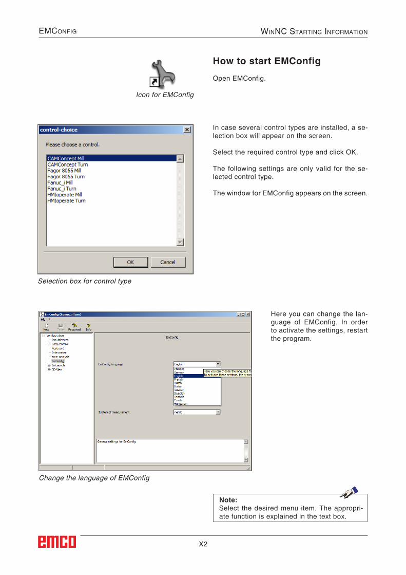
X2
EMConfig WinnC Starting inforMation
Change the language of EMConfig
How to start EMConfig
Open EMConfig.
In case several control types are installed, a se-lection box will appear on the screen.
Select the required control type and click OK.
The following settings are only valid for the se-lected control type.
The window for EMConfig appears on the screen.
Icon for EMConfig
Selection box for control type
Here you can change the lan-guage of EMConfig. In order to activate the settings, restart the program.
Note:Select the desired menu item. The appropri-ate function is explained in the text box.
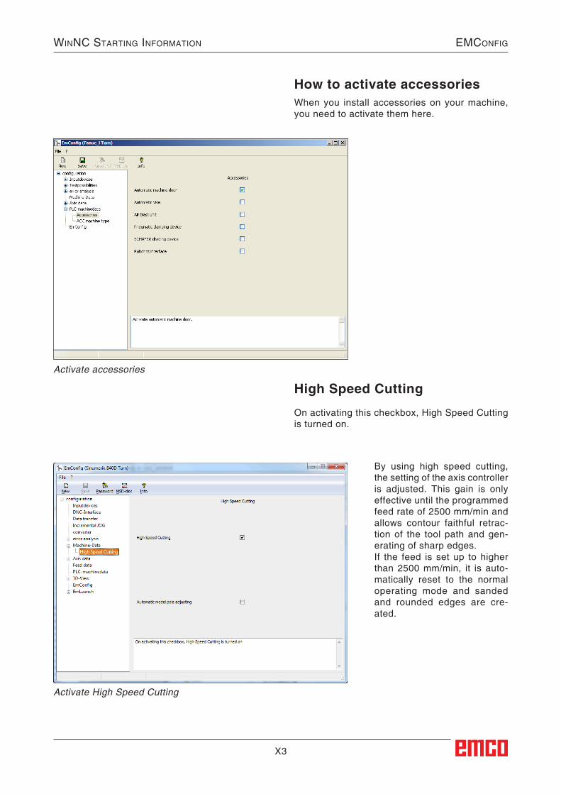
X3
WinnC Starting information EmConfig
How to activate accessoriesWhen you install accessories on your machine, you need to activate them here.
Activate accessories
High Speed Cutting
On activating this checkbox, High Speed Cutting is turned on.
Activate High Speed Cutting
By using high speed cutting, the setting of the axis controller is adjusted. This gain is only effective until the programmed feed rate of 2500 mm/min and allows contour faithful retrac-tion of the tool path and gen-erating of sharp edges. If the feed is set up to higher than 2500 mm/min, it is auto-matically reset to the normal operating mode and sanded and rounded edges are cre-ated.
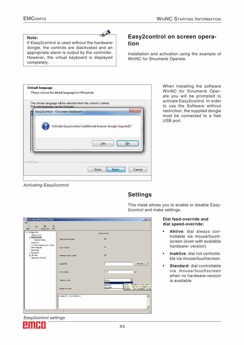
X4
EMConfig WinnC Starting inforMation
Settings
This mask allows you to enable or disable Easy-2control and make settings.
Easy2control on screen opera-tion
Installation and activation using the example of WinNC for Sinumerik Operate.
Easy2control settings
Activating Easy2control
Dial feed-override anddial speed-override:
• Aktive: dial always con-trollable via mouse/touch-screen (even with available hardware- version).
• Inaktive: dial not controlla-ble via mouse/touchscreen.
• Standard: dial controllable via mouse/touchscreen when no hardware-version is available.
Note:If Easy2control is used without the hardware-dongle, the controls are diactivated and an appropriate alarm is output by the controller.However, the virtual keyboard is displayed completely.
When installing the software WinNC for Sinumerik Oper-ate you will be prompted to activate Easy2control. In order to use the Software without restriction, the supplied dongle must be connected to a free USB port.
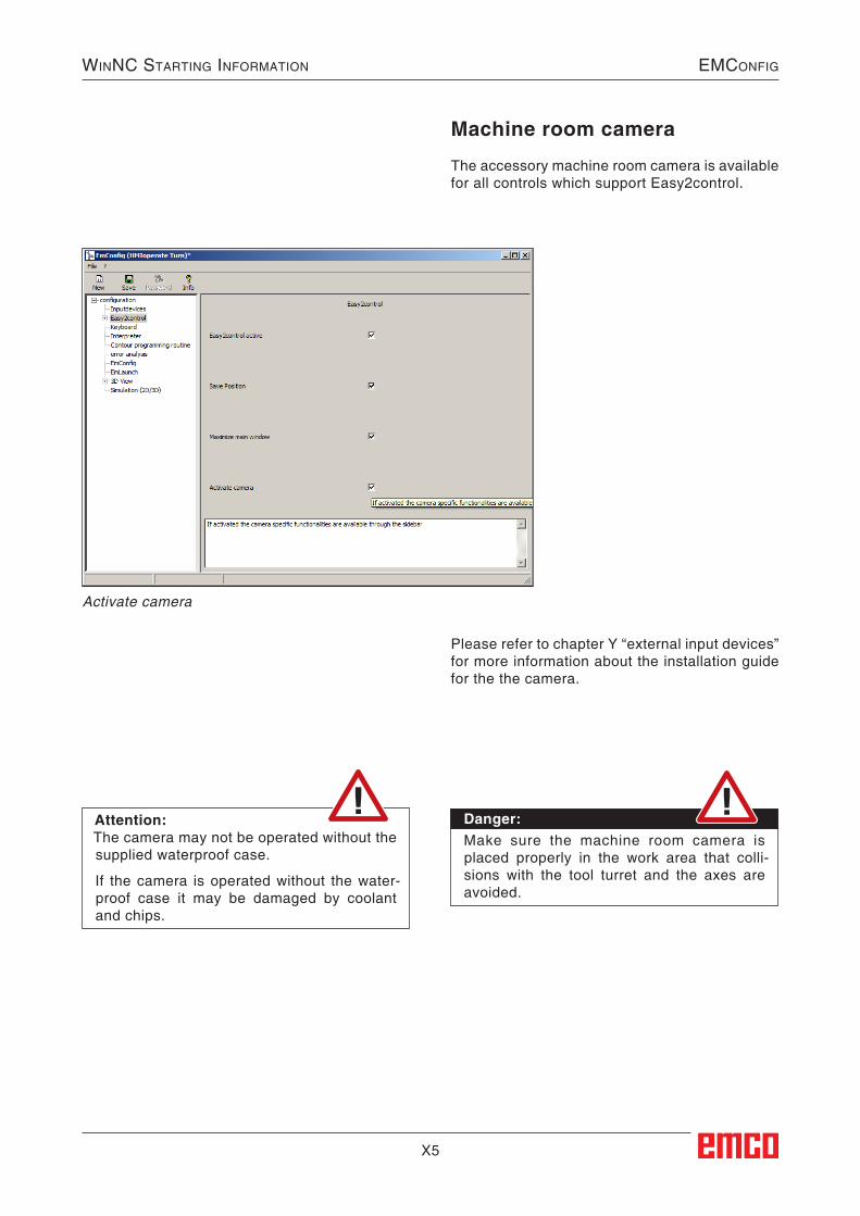
X5
WinnC Starting information EmConfig
Activate camera
Machine room camera
The accessory machine room camera is available for all controls which support Easy2control.
Please refer to chapter Y “external input devices” for more information about the installation guide for the the camera.
Danger:Make sure the machine room camera is placed properly in the work area that colli-sions with the tool turret and the axes are avoided.
Attention:The camera may not be operated without the supplied waterproof case.
If the camera is operated without the water-proof case it may be damaged by coolant and chips.
X6
EMConfig WinnC Starting inforMation
How to save changes
After the settings, the changes must be saved.
Select "Save" or click on the icon.
How to create machine data floppy disk or machine data USB flash drive
After having changed the machine data, the ma-chine data floppy disk or the machine data USB flash drive must be in the appropriate drive.Otherwise your changes cannot be saved and get lost.
After saving the changes, create a machine data floppy disk (MSD) or a machine data USB flash drive.
Note:Input fields highlighted in red indicate inad-missible values. Inadmissible values are not saved in EMConfig.
Z1
WinnC Starting information SoftWare inStallation
Z: Software Installation Windows
Variants of WinNCYou can install EMCO WinNC for the following CNC control types:
• WinNC for SINUMERIK Operate T and M• WinNC for FANUC 31i T and M• HEIDENHAIN TNC 426• Emco WinNC for HEIDENHAIN TNC 640• FAGOR 8055 TC and MC• CAMConcept T and M
In case there are several control types installed, a menu appears when starting EM Launch from which you can select the desired type.The following versions can be installed from the WinNC variants:
• Demo licence: The demo licence is valid for 30 days after the
first use. 5 days before the demo licence ex-pires, you can enter another valid licence key (see licence manager)
• Programming station: Programming and operation of the appropriate
CNC control type is simulated by WinNC on your PC.• Single user licence: Authorizes to external programming of CNC-
controlled machine tools on one PC worksta-tion.
• Multi-user licence: Authorizes to external programming of CNC-
controlled machine tools. The multi-user li-cence can be installed on an unlimited number of PC workstations or in a network within the institute registered by the licensor.
• Educational licence version: Is a time-limited multi-licence especially for
schools and educational institutes.
• Machine licence: This licence allows to directly operate a PC-
controlled machine (PC TURN, Concept TURN, PC MILL, Concept MILL) of WinNC as if it was operated by an ordinary CNC control.
System prerequisites
Machine with integrated control PC• All Concept machines• Machines that were converted to ACC• MOC with Windows 7 or higher (32 / 64 Bit)
Machines with included control PC and pro-gramming stations• Windows 7 or higher (32 / 64 Bit)• free hard drive space 400 MB• Programming station: 1*USB, machine version:
2*USB• TCP/IP-capable network card for machine ver-
sion)
Recommended system prerequisites• PC Dual Core• Working memory 4 GB RAM• free hard drive space 2 GB
Software installation• Start Windows• Start the installation application on the USB
stick or your download file.• Follow the instructions from the installation
guide.
For more informations regarding software instal-lation and / or software update please refer to the documentation “short description for WinNC update installation”.
Note:PC TURN and PC MILL have to be equipped with the conversion kit for ACC in order to operate EMCO WinNC.
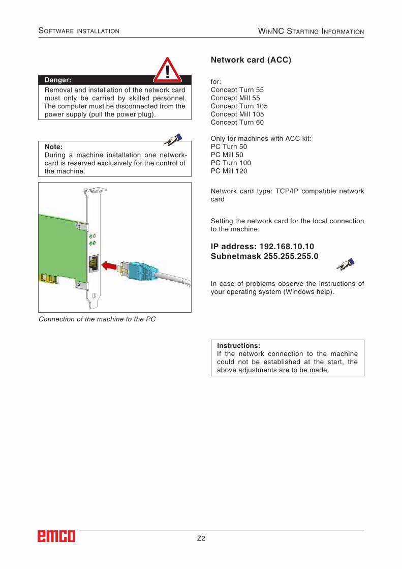
Z2
Software inStallation winnC Starting information
Network card (ACC)
Setting the network card for the local connection to the machine:
IP address: 192.168.10.10Subnetmask 255.255.255.0
for:Concept Turn 55Concept Mill 55Concept Turn 105 Concept Mill 105Concept Turn 60
Only for machines with ACC kit:PC Turn 50PC Mill 50PC Turn 100PC Mill 120
Network card type: TCP/IP compatible network card
Connection of the machine to the PC
In case of problems observe the instructions of your operating system (Windows help).
Danger:Removal and installation of the network card must only be carried by skilled personnel.The computer must be disconnected from the power supply (pull the power plug).
Note:During a machine installation one network-card is reserved exclusively for the control of the machine.
Instructions:If the network connection to the machine could not be established at the start, the above adjustments are to be made.
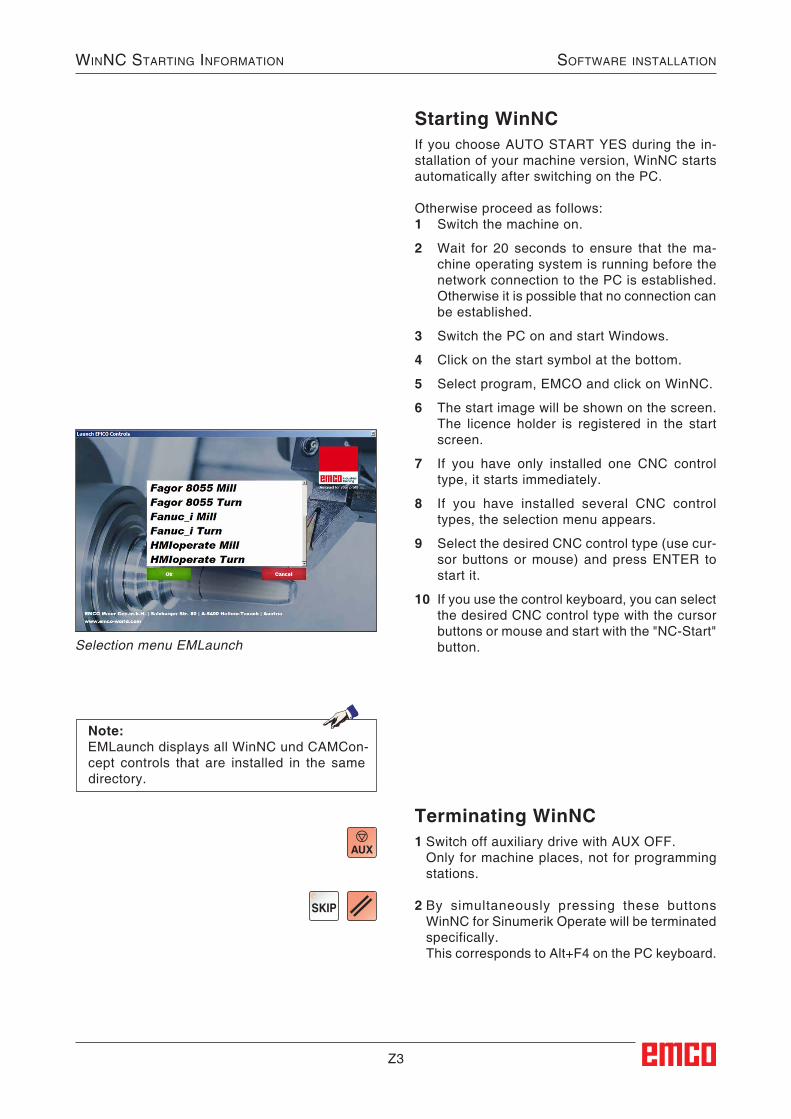
Z3
WinnC Starting information SoftWare inStallation
Starting WinNCIf you choose AUTO START YES during the in-stallation of your machine version, WinNC starts automatically after switching on the PC.
Otherwise proceed as follows:1 Switch the machine on.
2 Wait for 20 seconds to ensure that the ma-chine operating system is running before the network connection to the PC is established. Otherwise it is possible that no connection can be established.
3 Switch the PC on and start Windows.
4 Click on the start symbol at the bottom.
5 Select program, EMCO and click on WinNC.
6 The start image will be shown on the screen. The licence holder is registered in the start screen.
7 If you have only installed one CNC control type, it starts immediately.
8 If you have installed several CNC control types, the selection menu appears.
9 Select the desired CNC control type (use cur-sor buttons or mouse) and press ENTER to start it.
10 If you use the control keyboard, you can select the desired CNC control type with the cursor buttons or mouse and start with the "NC-Start" button.
Terminating WinNC1 Switch off auxiliary drive with AUX OFF. Only for machine places, not for programming
stations.
2 By simultaneously pressing these buttons WinNC for Sinumerik Operate will be terminated specifically.
This corresponds to Alt+F4 on the PC keyboard.
Selection menu EMLaunch
Note:EMLaunch displays all WinNC und CAMCon-cept controls that are installed in the same directory.
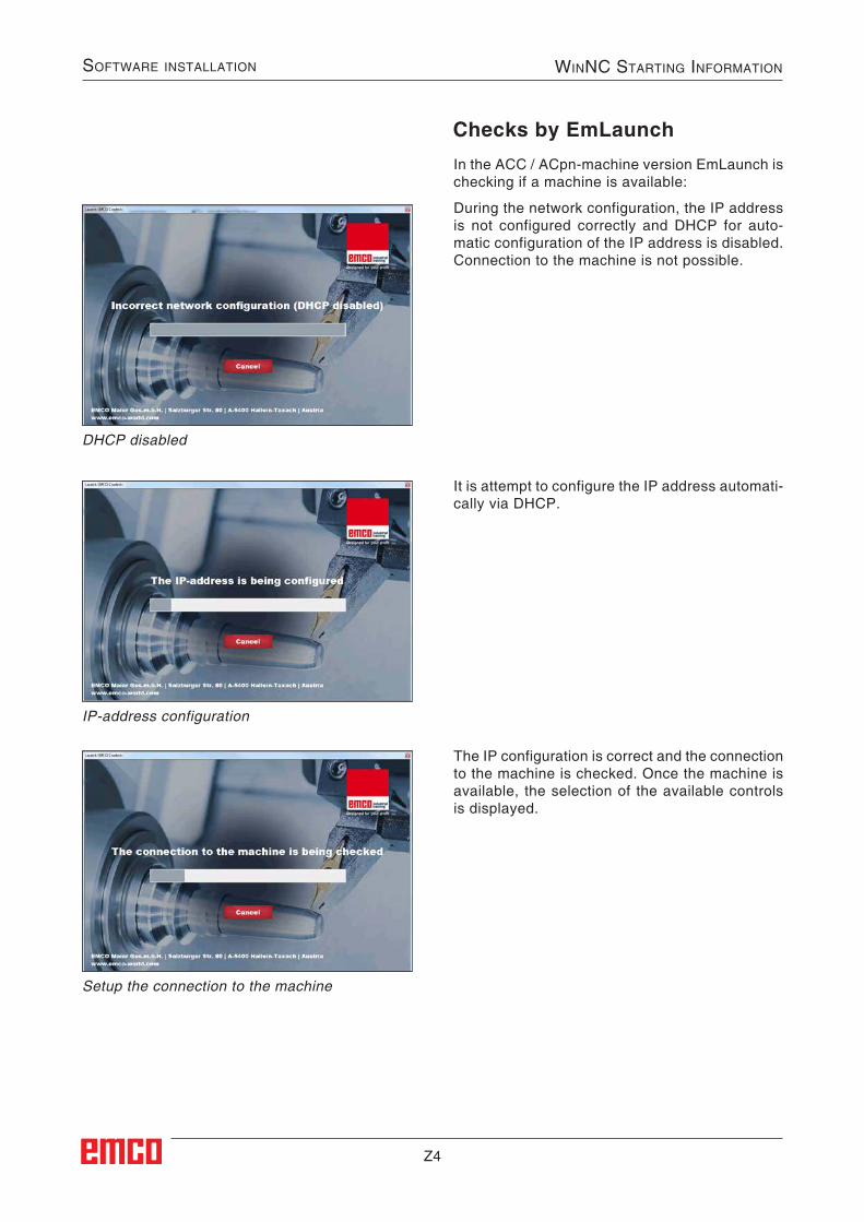
Z4
Software inStallation winnC Starting information
In the ACC / ACpn-machine version EmLaunch is checking if a machine is available:
During the network configuration, the IP address is not configured correctly and DHCP for auto-matic configuration of the IP address is disabled. Connection to the machine is not possible.
DHCP disabled
IP-address configuration
Setup the connection to the machine
Checks by EmLaunch
It is attempt to configure the IP address automati-cally via DHCP.
The IP configuration is correct and the connection to the machine is checked. Once the machine is available, the selection of the available controls is displayed.
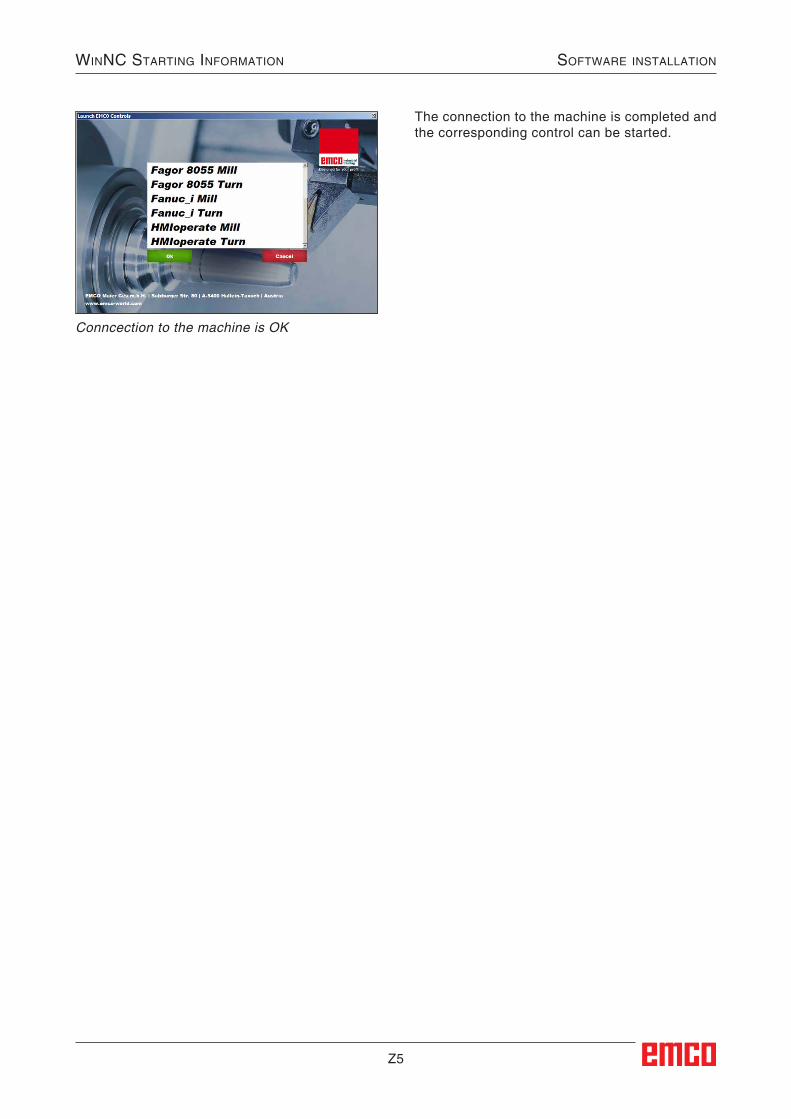
Z5
WinnC Starting information SoftWare inStallation
Conncection to the machine is OK
The connection to the machine is completed and the corresponding control can be started.
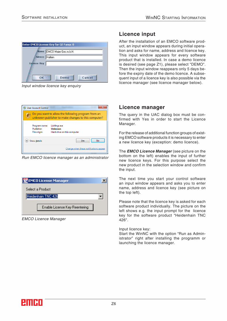
Z6
Software inStallation winnC Starting information
EMCO Licence Manager
Input window licence key enquiry
Licence managerThe query in the UAC dialog box must be con-firmed with Yes in order to start the Licence Manager.
For the release of additional function groups of exist-ing EMCO software products it is necessary to enter a new licence key (exception: demo licence).
The EMCO Licence Manager (see picture on the bottom on the left) enables the input of further new licence keys. For this purpose select the new product in the selection window and confirm the input.
The next time you start your control software an input window appears and asks you to enter name, address and licence key (see picture on the top left).
Please note that the licence key is asked for each software product individually. The picture on the left shows e.g. the input prompt for the licence key for the software product "Heidenhain TNC 426".
Input licence key:Start the WinNC with the option “Run as Admin-istrator” right after installing the programm or launching the licence manager.
Licence inputAfter the installation of an EMCO software prod-uct, an input window appears during initial opera-tion and asks for name, address and licence key. This input window appears for every software product that is installed. In case a demo licence is desired (see page Z1), please select "DEMO".Then the input window reappears only 5 days be-fore the expiry date of the demo licence. A subse-quent input of a licence key is also possible via the licence manager (see licence manager below).
Run EMCO licence manager as an administrator