Embed Size (px)
Citation preview
EMC CorporationCorporate Headquarters:
Hopkinton, MA 01748-9103
1-508-435-1000www.EMC.com
EMC Rails and Enclosuresfor 19-Inch NEMA Cabinets
INSTALLATION GUIDE
P/N 014003082REV A05
EMC Rails and Enclosures Installation Guide for 19-Inch NEMA Cabinetsii
Copyright ©2001-2003 EMC Corporation. All rights reserved.
Published December, 2003
EMC believes the information in this publication is accurate as of its publication date. The information is subject to change without notice.
THE INFORMATION IN THIS PUBLICATION IS PROVIDED "AS IS." EMC CORPORATION MAKES NO REPRESENTATIONS OR WARRANTIES OF ANY KIND WITH RESPECT TO THE INFORMATION IN THIS PUBLICATION, AND SPECIFICALLY DISCLAIMS IMPLIED WARRANTIES OF MERCHANTABILITY OR FITNESS FOR A PARTICULAR PURPOSE.
Use, copying, and distribution of any EMC software described in this publication requires an applicable software license.
Trademark InformationEMC2, EMC, CLARiiON, Navisphere, and PowerPath are registered trademarks and Access Logix, EMC ControlCenter, FLARE, MirrorView, SAN Copy, and SnapView are trademarks of EMC Corporation.
All other trademarks used herein are the property of their respective owners.
EMC Rails and Enclosures Installation Guide for 19-Inch NEMA Cabinets iii
Preface........................................................................................................................... vii
Warnings and Cautions ......................................................................................... xiii
Chapter 1 Determining Where to Install Devices in the CabinetDevice Placement Requirements ................................................... 1-2
Position in the Cabinet ............................................................. 1-2Device Height Requirements ......................................................... 1-5
Chapter 2 Installing Mounting Trays, Rails and 1U SPSsBefore You Begin .............................................................................. 2-2
Tools and Equipment ............................................................... 2-3SPS Mounting Kit............................................................................. 2-4Installing Adjustable Rails to the SPS Tray .................................. 2-5Installing the SPS Tray Assembly .................................................. 2-8Installing an SPS in the Tray......................................................... 2-12
Chapter 3 Installing Mounting Rails and the 1U Control Station AssemblyBefore You Begin .............................................................................. 3-2
Tools and Equipment ............................................................... 3-3Control Station Mounting Kit ........................................................ 3-4Installing Mounting Rails for the Control Station....................... 3-5Installing the Control Station Assembly..................................... 3-11
Contents
EMC Rails and Enclosures Installation Guide for 19-Inch NEMA Cabinetsiv
Contents
Chapter 4 Installing Mounting Rails and 3U and 4U EnclosuresBefore You Begin.............................................................................. 4-2
Tools and Equipment ............................................................... 4-3Installing the 3U and 4U Enclosures...................................... 4-3
3U and 4U Mounting Kits .............................................................. 4-4Installing the Mounting Rails ........................................................ 4-5Installing a 4U Enclosure in the Cabinet .................................... 4-12Installing a 3U Enclosure in the Cabinet .................................... 4-18
Chapter 5 Installing Front Filler PanelsInstalling the 1U or 3U Latch Bracket........................................... 5-2Installing the 2U Latch Brackets .................................................... 5-5Installing the Filler Panel................................................................ 5-7
Appendix A Servicing a 40U CabinetHandling FRUs .............................................................................. A-2Removing and Replacing a PDU Strip ....................................... A-3Removing and Replacing the Fan Module ................................ A-6
Appendix B 40U Cabinet Technical Specificationsac Power Specifications ................................................................. B-2Sizes and Weights .......................................................................... B-3Agency Standards .......................................................................... B-3

EMC Rails and Enclosures Installation Guide for 19-Inch NEMA Cabinets v
Figures1-1 Sample Device Placements with a DPE2 ................................................... 1-21-2 Sample Device Placement with an SPE ..................................................... 1-31-3 Sample Device Placement with a DME, SPE, and Control Station ....... 1-41-4 U Increments in a 40U Cabinet Front Channel ........................................ 1-62-1 EMC 40U Cabinet Front and Rear Views ................................................. 2-22-2 Removing the Cabinet Sides from an EMC 40U Cabinet ....................... 2-32-3 SPS Adjustable Rails .................................................................................... 2-52-4 Securing the SPS Adjustment Rails to the SPS Tray ................................ 2-62-5 Inserting the Clip Nuts on the Adjustable Range Flange ....................... 2-72-6 SPS Mounting Tray ...................................................................................... 2-82-7 Inserting the Clip Nuts on the Front Channels ........................................ 2-92-8 Securing the Tray, Tightening the Adjustment Screws, and
Installing the Latch Brackets ....................................................................... 2-102-9 Installing the SPS Tray in a Cabinet with Square-Hole Channels ....... 2-112-10 Fastening the Attachment Brackets to the SPS ....................................... 2-122-11 Securing the Right and Left Brackets ....................................................... 2-132-12 Securing the Middle Bracket ..................................................................... 2-142-13 Fastening the SPS Units to the Front of the Tray ................................... 2-152-14 Attaching the SPS Mounting Tray Bezel ................................................. 2-163-1 EMC 40U Cabinet Front and Rear Views ................................................. 3-23-2 Removing the Cabinet Sides from an EMC 40U Cabinet ....................... 3-33-3 Control Station Adjustable Mounting Rails ............................................. 3-53-4 Installing Clip Nuts for Securing Mounting Rails to Cabinet
Channels .......................................................................................................... 3-63-5 Removing/Installing the Adjustable Rails ............................................... 3-73-6 Adjusting Rail Length .................................................................................. 3-73-7 Securing Front Rail to the Front Channel ................................................. 3-83-8 Securing Rear Rail to the Rear Round-Hole Channel ............................. 3-93-9 Securing the Rear Rail to the Rear Square-Hole Channel .................... 3-10
Figures
vi EMC Rails and Enclosures Installation Guide for 19-Inch NEMA Cabinets
Figures
3-10 Installing Latch Brackets ............................................................................ 3-103-11 Sliding the 1U Control Station Assembly into the Rails ........................ 3-113-12 Installing the Securing Screws and Front Bezel ...................................... 3-124-1 EMC 40U Cabinet Front and Rear Views .................................................. 4-24-2 Removing the Cabinet Sides from a 40U Cabinet .................................... 4-34-3 Enclosure Mounting Rails ............................................................................ 4-54-4 Front View of the Rail Flanges (Above SPS Tray) .................................... 4-64-5 Front View of the Rail Flanges (Above 4U Enclosure) ............................ 4-74-6 Removing/Installing the Adjustable Rails ................................................ 4-84-7 Adjusting Rail Length .................................................................................. 4-94-8 Attaching Clip Nuts to the Flanges ............................................................ 4-94-9 Securing the Rails to the Channels ........................................................... 4-104-10 Installing Clip Nuts to Secure Enclosures to Cabinet Channels ......... 4-114-11 Attaching Latch Brackets to a 4U Enclosure ........................................... 4-134-12 Sliding the 4U Enclosure onto the Mounting Rails ................................ 4-144-13 Securing the Rear of the Enclosure ........................................................... 4-154-14 Securing the 4U Enclosure to the Channels ............................................ 4-164-15 Attaching the 4U Front Bezel .................................................................... 4-174-16 Attaching Latch Brackets to a 3U Enclosure ........................................... 4-194-17 Installing the Rails for the 3U Enclosure ................................................. 4-204-18 Sliding the 3U Enclosure onto the Mounting Rails ................................ 4-214-19 Securing the Rear of the 3U Enclosure ..................................................... 4-224-20 Securing the 3U Enclosure to the Channels ............................................ 4-234-21 Attaching the 3U Front Bezel .................................................................... 4-245-1 Location of the 3U Latch Bracket ................................................................ 5-25-2 Installing the 1U or 3U Latch Bracket on the Left Channel .................... 5-35-3 Installing the 1U or 3U Latch Bracket on the Right Channel .................. 5-45-4 Installing the 2U Latch Bracket on the Left Channel ............................... 5-55-5 Installing the 2U Latch Bracket on the Right Channel ............................ 5-65-6 Installing a Filler Panel (1U Shown) ........................................................... 5-7A-1 Removing the Side Panel ............................................................................ A-3A-2 Freeing the Power Cord .............................................................................. A-4A-3 Removing the PDU Strip Screws ............................................................... A-5A-4 Loosening the Captive Screws ................................................................... A-6A-5 Pulling the Fan Module from the Slots ..................................................... A-7A-6 Installing the Fan Module ........................................................................... A-7
EMC Rails and Enclosures Installation Guide for 19-Inch NEMA Cabinets vii
Preface
As part of an effort to improve and enhance the performance and capabilities of its product line, EMC from time to time releases revisions of its hardware and software. Therefore, some functions described in this guide may not be supported by all revisions of the software or hardware currently in use. For the most up-to-date information on product features, refer to your product release notes.
If a product does not function properly or does not function as described in this guide, please contact your EMC representative.
About This Manual This manual explains how to install hardware in cabinets that conform to National Electrical Manufacturer’s Association (NEMA) standards for 19-inch cabinets (in which the left and right mounting channels are 19 inches apart). In most cases, the illustrations and examples describe EMC’s standard cabinet, which is 40U tall. This manual covers the following EMC hardware:
◆ Mounting hardware, including the 1U SPS tray and rails for 3U and 4U enclosures
◆ Standby Power Supplies (SPSs) for Fibre Channel enclosures ◆ 1U Control Station assembly◆ 4U processor enclosures ◆ 3U disk array/processor enclosures◆ Filler panels◆ 40U cabinet with 19-inch NEMA channels
Instructions for adding Fibre Channel switches to an EMC storage system are included in the device-specific documentation that accompanies the switch.
viii EMC Rails and Enclosures Installation Guide for 19-Inch NEMA Cabinets
Preface
Audience This guide is intended for use by trained technical personnel familiar with NEMA mounting hardware.
Organization This guide contains five chapters, as follows:
RelatedDocumentation
This guide refers to various documents that provide detailed descriptions of each step. Related documents include:
◆ EMC Site Preparation and Unpacking Guide for the 40U Cabinet (P/N 014003100)
◆ EMC Cabinet Setup Guide for the 40U Cabinet (P/N 014003099)
◆ EMC CLARiiON CX300, CX500, and CX700 Storage Systems Configuration Planning Guide (P/N 300-001-273)
◆ EMC Storage Systems CX400-Series and CX600-Series Configuration Planning Guide (P/N 014003113)
◆ EMC Storage Systems CX200-Series Configuration Planning Guide (P/N 014003115)
◆ EMC CLARiiON CX300 2-Gigabit Disk Processor Enclosure (DPE2) Hardware Reference (P/N 300-001-276)
◆ EMC CLARiiON CX500 2-Gigabit Disk Processor Enclosure (DPE2) Hardware Reference (P/N 300-001-275)
◆ EMC CLARiiON CX700 Storage Processor Enclosure (SPE) Hardware Reference (P/N 300-001-274)
Chapter 1 Discusses device placement and device height requirements.
Chapter 2 Discusses the installation of the mounting tray for the 1U standby power supply (SPS) and describes the installation of the SPSs.
Chapter 3 Describes the installation of mounting rails and the 1U Control Station assembly.
Chapter 4 Describes installation of mounting rails and enclosures for 3U and 4U devices.
Chapter 5 Describes installation of latch brackets and filler panels.
Appendix A Explains how to remove and replace field replaceable units (FRUs) in EMC’s standard 40U cabinet; specifically the fan module and the power distribution unit (PDU) strip.
Appendix B Provides technical specifications of EMC’s standard 40U cabinet.
EMC Rails and Enclosures Installation Guide for 19-Inch NEMA Cabinets ix
Preface
◆ EMC Storage Processor Enclosure (SPE) CX600-Series Hardware Reference (P/N 014003076)
◆ EMC 2-Gigabit Disk-Array Enclosure (DAE2) Hardware Reference (P/N 014003048)
◆ EMC 2-Gigabit Disk Processor Enclosure (DPE2) CX400-Series Hardware Reference (P/N 014003049)
◆ EMC 2-Gigabit Disk Processor Enclosure (DPE2) CX200-Series Hardware Reference (P/N 014003118)
◆ EMC Celerra NS600 Hardware Reference Guide (P/N 300-000-817)
Conventions Used inThis Guide
EMC uses the following conventions for notes, cautions, warnings, and danger notices.
A note presents information that is important, but not hazard-related.
CAUTION!A caution contains information essential to avoid data loss or damage to the system or equipment. The caution may apply to hardware or software.
WARNING
A warning contains information essential to avoid a hazard that can cause severe personal injury, death, or substantial property damage if you ignore the warning.
DANGER
A danger notice contains information essential to avoid a hazard that will cause severe personal injury, death, or substantial property damage if you ignore the message.
x EMC Rails and Enclosures Installation Guide for 19-Inch NEMA Cabinets
Preface
Typographical Conventions
This guide uses the following format conventions:
Finding CurrentInformation
The most up-to-date information about rails and enclosures for the 19-inch NEMA cabinets, is posted on the EMC Powerlink website. We recommend that you download the latest information before you install or setup the rails and enclosures.
To access EMC Powerlink, use the following link:
http://powerlink.emc.com
After you log in, select Support > Document Library and find the following
◆ The FLARE™ release notes.
◆ The latest version of this guide.
◆ EMC Installation Roadmap for CX-Series and FC-Series Storage Systems, which provides a checklist of the tasks that you must complete to install your storage system in a storage area network (SAN) or direct attach configuration.
Where to Get Help For questions about technical support, call your local sales office or service provider.
If you have a valid EMC service contract, contact EMC Customer Service at:
This typeface Indicates text (including punctuation) that you type verbatim, all commands, pathnames, filenames, and directory names. It indicates the name of a dialog box, field in a dialog box, menu, menu option, or button.
This typeface Represents variables for which you supply the values; for example, the name of a directory or file, your username or password, and explicit arguments to commands.
x > y Represents a menu path. For example, Operations > Poll All Storage Systems tells you to select Poll All Storage Systems on the Operations menu.
United States: (800) 782-4362 (SVC-4EMC)
Canada: (800) 543-4782 (543-4SVC)
Worldwide: (508) 497-7901
EMC Rails and Enclosures Installation Guide for 19-Inch NEMA Cabinets xi
Preface
Follow the voice menu prompts to open a service call and select the applicable product support.
Sales and CustomerService Contacts
For the list of EMC sales locations, please access the EMC home page at:
http://www.EMC.com/contact/
For additional information on the EMC products and services available to customers and partners, refer to the EMC Powerlink Web site at:
http://powerlink.EMC.com
Your Comments Your suggestions will help us continue to improve the accuracy, organization, and overall quality of the user publications. Please send a message to [email protected] with your opinions of this guide.
xii EMC Rails and Enclosures Installation Guide for 19-Inch NEMA Cabinets
Preface

EMC Rails and Enclosures Installation Guide for 19-Inch NEMA Cabinets xiii
The following warnings and cautions pertain throughout this guide.
WARNING Trained service personnel only.
This unit has two power supply cords. To reduce the risk of electric shock, disconnect both power supply cords before servicing.
Ground circuit continuity is vital for safe operation of the machine. Never operate the machine with grounding conductors disconnected. Remember to reconnect any grounding conductors removed for or during any installation procedure.
ATTENTION Resérvé au personnel autorisé.
Cet appareil comporte plus d'un cordon d'alimentation. Afin de prévenir les chocs électriques, débrancher les deux cordons d'alimentation avant de faire le dépannage.
Un circuit de terre continu est essentiel en vue du fonctionnement sécuritaire de l'apareil. Ne jamais mettre l'appareil en marche lorsque le conducteur de mise a la terre est débranché.
WARNUNG Nur für Fachpersonal.
Das Geraet hat mehr als eine Anschlussleitung. Zur Vermeidung der Gefahr eines elektrischen Schlages sind vor dem öffnen beide Anschlussleitungen vom Netz zu trennen.
STROMSTREUVERLUST: Gerät muss geerdet werden, bevor es am Stromnetz angeschlossen wird.
Warnings andCautions
xiv EMC Rails and Enclosures Installation Guide for 19-Inch NEMA Cabinets
Warnings and Cautions
WARNING
The system operates at high voltages. To protect against physical harm, power off the system whenever possible while servicing.
CAUTION!Trained personnel are advised to exercise great care at all times when working on the unit. Remember to:
◆ Remove rings, watches, or other jewelry and neckties before you begin any procedures.
◆ Use caution near any moving part and any part that may start unexpectedly such as fans, motors, solenoids, etc.
◆ Always use the correct tools for the job.
◆ Always use the correct replacement parts.
◆ Keep all paperwork, including incident reports, up to date, complete, and accurate.
Determining Where to Install Devices in the Cabinet 1-1
1
This chapter discusses the device placement and height requirements for SPSs, 3U and 4U enclosures. Major topics include
◆ Device Placement Requirements .....................................................1-2◆ Device Height Requirements ...........................................................1-5
Determining Where toInstall Devices in the
Cabinet
1-2 EMC Rails and Enclosures Installation Guide for 19-Inch NEMA Cabinets
Determining Where to Install Devices in the Cabinet
Device Placement RequirementsBefore attaching the mounting rails or trays in any cabinet, you must decide where to put them. Where you install the devices depends on the kinds of devices you will install and the height of each device.
Position in the Cabinet
Devices with internal cooling fans that move air from front to back (or vice versa) and not from beneath or above have no special cooling requirements that direct placement in the cabinet. All of the storage systems and enclosures mentioned in this document have fans that move air from front to back.
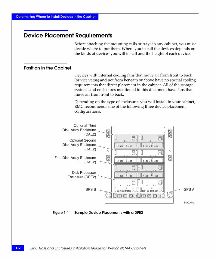
Depending on the type of enclosures you will install in your cabinet, EMC recommends one of the following three device placement configurations.
Figure 1-1 Sample Device Placements with a DPE2
EMC2670
Disk ProcessorEnclosure (DPE2)
SPS B SPS A
Optional ThirdDisk-Array Enclosure
(DAE2)
Optional SecondDisk-Array Enclosure
(DAE2)
First Disk-Array Enclosure(DAE2)
Device Placement Requirements 1-3
Determining Where to Install Devices in the Cabinet
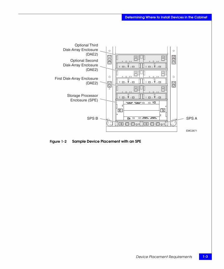
Figure 1-2 Sample Device Placement with an SPE
EMC2671
SPS B SPS A
Optional ThirdDisk-Array Enclosure
(DAE2)
Optional SecondDisk-Array Enclosure
(DAE2)
First Disk-Array Enclosure(DAE2)
Storage ProcessorEnclosure (SPE)
1-4 EMC Rails and Enclosures Installation Guide for 19-Inch NEMA Cabinets
Determining Where to Install Devices in the Cabinet
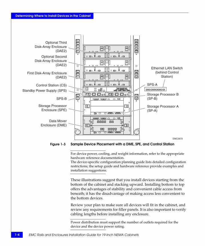
Figure 1-3 Sample Device Placement with a DME, SPE, and Control Station
For device power, cooling, and weight information, refer to the appropriate hardware reference documentation.The device-specific configuration planning guide lists detailed configuration restrictions; the setup guide and hardware reference provide examples and installation suggestions.
These illustrations suggest that you install devices starting from the bottom of the cabinet and stacking upward. Installing bottom to top offers the advantages of stability and convenient cable access from beneath; it has the disadvantage of making access less convenient to the bottom devices.
Review your plan to make sure all devices will fit in the cabinet, and review any requirements for filler panels. It is also important to verify cabling lengths before installing any enclosure.
Power distribution must support the number of outlets required for the device and the device power rating.
16
1615
15
13
13
14
14
12
12
11
11
Optional ThirdDisk-Array Enclosure
(DAE2)
Optional SecondDisk-Array Enclosure
(DAE2)
First Disk-Array Enclosure(DAE2)
Control Station (CS)
Standby Power Supply (SPS)
SPS-B
Storage ProcessorEnclosure (SPE)
Data MoverEnclosure (DME)
SPS-A
Storage Processor B (SP-B)
Storage Processor A (SP-A)
Ethernet LAN Switch(behind Control
Station)
EMC2672
Device Height Requirements 1-5
Determining Where to Install Devices in the Cabinet
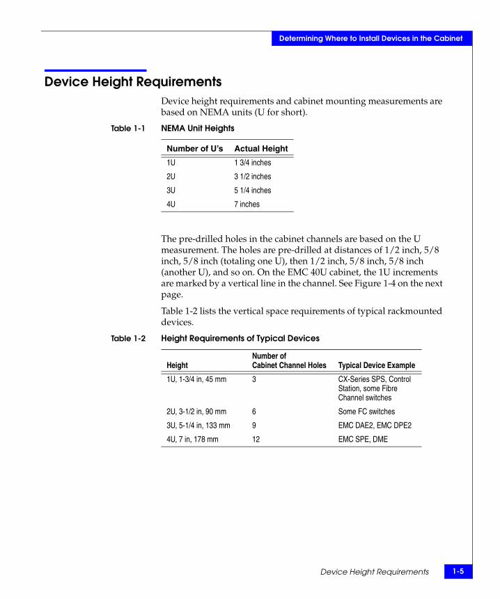
Device Height RequirementsDevice height requirements and cabinet mounting measurements are based on NEMA units (U for short).
Table 1-1 NEMA Unit Heights
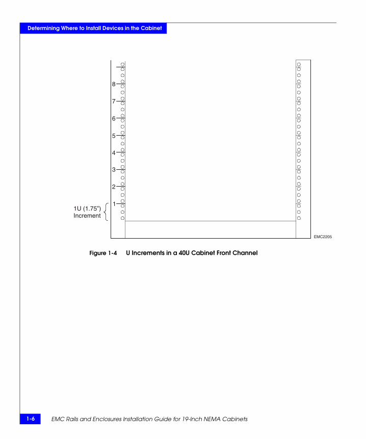
The pre-drilled holes in the cabinet channels are based on the U measurement. The holes are pre-drilled at distances of 1/2 inch, 5/8 inch, 5/8 inch (totaling one U), then 1/2 inch, 5/8 inch, 5/8 inch (another U), and so on. On the EMC 40U cabinet, the 1U increments are marked by a vertical line in the channel. See Figure 1-4 on the next page.
Table 1-2 lists the vertical space requirements of typical rackmounted devices.
Table 1-2 Height Requirements of Typical Devices
Number of U’s Actual Height
1U 1 3/4 inches
2U 3 1/2 inches
3U 5 1/4 inches
4U 7 inches
HeightNumber of Cabinet Channel Holes Typical Device Example
1U, 1-3/4 in, 45 mm 3 CX-Series SPS, Control Station, some Fibre Channel switches
2U, 3-1/2 in, 90 mm 6 Some FC switches
3U, 5-1/4 in, 133 mm 9 EMC DAE2, EMC DPE2
4U, 7 in, 178 mm 12 EMC SPE, DME
1-6 EMC Rails and Enclosures Installation Guide for 19-Inch NEMA Cabinets
Determining Where to Install Devices in the Cabinet
Figure 1-4 U Increments in a 40U Cabinet Front Channel
EMC2205
1
2
3
4
5
6
7
8
1U (1.75”)Increment
Installing Mounting Trays, Rails and 1U SPSs 2-1
2
This chapter discusses the installation of the mounting tray for 1U devices such as EMC’s standard standby power supplies (SPS). It also describes how to mount an SPS on the tray, and the materials you will need for mounting these items in the cabinets.
Major topics include
◆ Before You Begin ................................................................................2-2◆ SPS Mounting Kit...............................................................................2-4◆ Installing Adjustable Rails to the SPS Tray ....................................2-5◆ Installing the SPS Tray Assembly ....................................................2-8◆ Installing an SPS in the Tray...........................................................2-12
Instructions for adding Fibre Channel switches to an EMC storage system are included in the device-specific documentation that accompanies the switch.
InstallingMounting Trays, Rails
and 1U SPSs
2-2 EMC Rails and Enclosures Installation Guide for 19-Inch NEMA Cabinets
Installing Mounting Trays, Rails and 1U SPSs
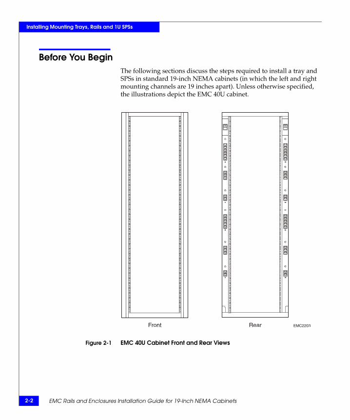
Before You BeginThe following sections discuss the steps required to install a tray and SPSs in standard 19-inch NEMA cabinets (in which the left and right mounting channels are 19 inches apart). Unless otherwise specified, the illustrations depict the EMC 40U cabinet.
Figure 2-1 EMC 40U Cabinet Front and Rear Views
EMC2203Front Rear
Before You Begin 2-3
Installing Mounting Trays, Rails and 1U SPSs
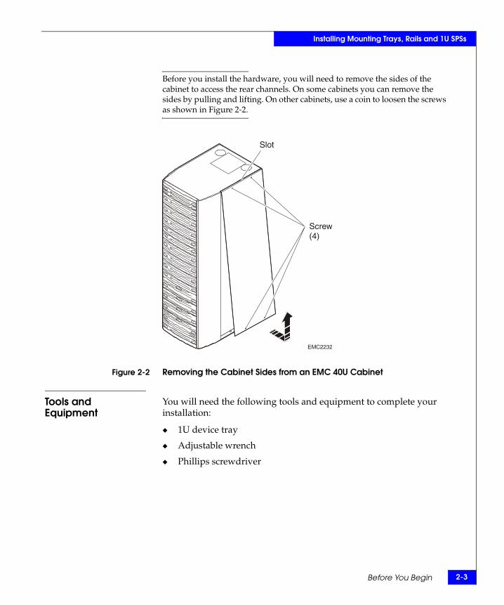
Before you install the hardware, you will need to remove the sides of the cabinet to access the rear channels. On some cabinets you can remove the sides by pulling and lifting. On other cabinets, use a coin to loosen the screws as shown in Figure 2-2.
Figure 2-2 Removing the Cabinet Sides from an EMC 40U Cabinet
Tools and Equipment
You will need the following tools and equipment to complete your installation:
◆ 1U device tray
◆ Adjustable wrench
◆ Phillips screwdriver
EMC2232
Slot
Screw(4)
2-4 EMC Rails and Enclosures Installation Guide for 19-Inch NEMA Cabinets
Installing Mounting Trays, Rails and 1U SPSs
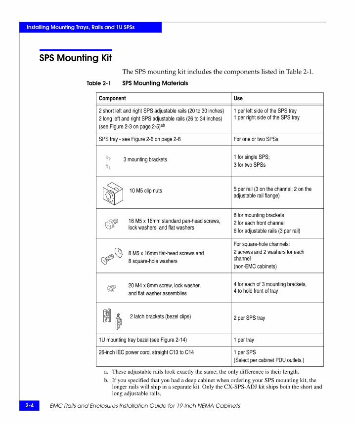
SPS Mounting KitThe SPS mounting kit includes the components listed in Table 2-1.
Table 2-1 SPS Mounting Materials
Component Use
2 short left and right SPS adjustable rails (20 to 30 inches)2 long left and right SPS adjustable rails (26 to 34 inches)(see Figure 2-3 on page 2-5)ab
a. These adjustable rails look exactly the same; the only difference is their length.
b. If you specified that you had a deep cabinet when ordering your SPS mounting kit, the longer rails will ship in a separate kit. Only the CX-SPS-ADJ kit ships both the short and long adjustable rails.
1 per left side of the SPS tray1 per right side of the SPS tray
SPS tray - see Figure 2-6 on page 2-8 For one or two SPSs
3 mounting brackets 1 for single SPS;3 for two SPSs
10 M5 clip nuts 5 per rail (3 on the channel; 2 on the adjustable rail flange)
16 M5 x 16mm standard pan-head screws, lock washers, and flat washers
8 for mounting brackets 2 for each front channel6 for adjustable rails (3 per rail)
8 M5 x 16mm flat-head screws and8 square-hole washers
For square-hole channels:2 screws and 2 washers for each channel(non-EMC cabinets)
20 M4 x 8mm screw, lock washer,and flat washer assemblies
4 for each of 3 mounting brackets,4 to hold front of tray
2 latch brackets (bezel clips) 2 per SPS tray
1U mounting tray bezel (see Figure 2-14) 1 per tray
26-inch IEC power cord, straight C13 to C14 1 per SPS(Select per cabinet PDU outlets.)
Installing Adjustable Rails to the SPS Tray 2-5
Installing Mounting Trays, Rails and 1U SPSs
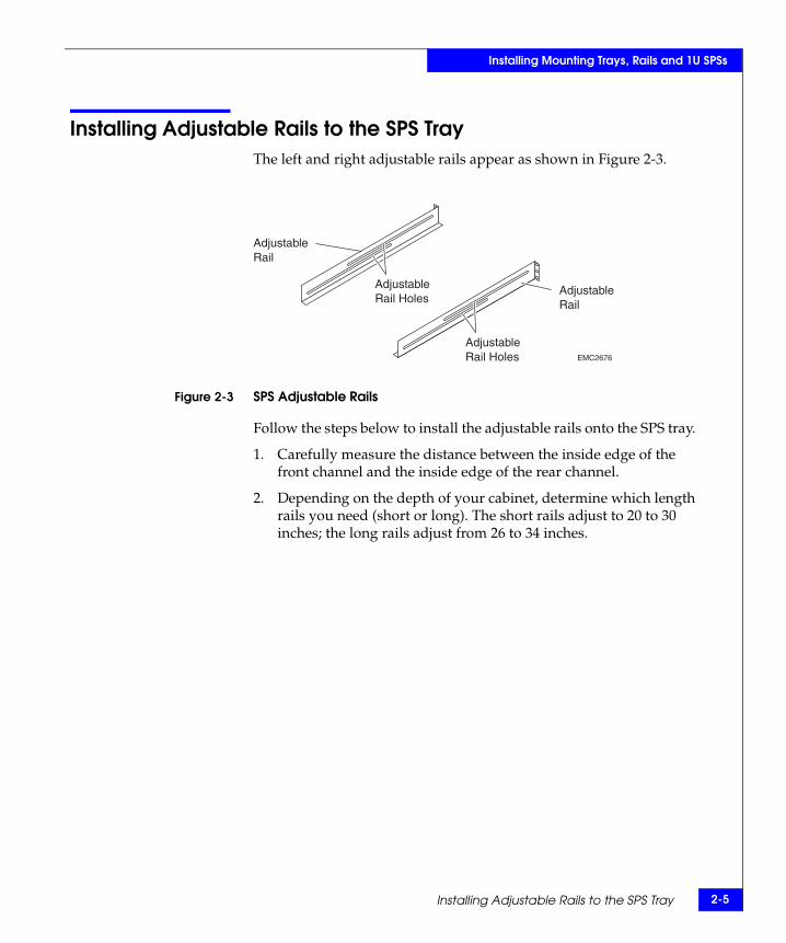
Installing Adjustable Rails to the SPS TrayThe left and right adjustable rails appear as shown in Figure 2-3.
Figure 2-3 SPS Adjustable Rails
Follow the steps below to install the adjustable rails onto the SPS tray.
1. Carefully measure the distance between the inside edge of the front channel and the inside edge of the rear channel.
2. Depending on the depth of your cabinet, determine which length rails you need (short or long). The short rails adjust to 20 to 30 inches; the long rails adjust from 26 to 34 inches.
EMC2676
AdjustableRail
AdjustableRail
AdjustableRail Holes
AdjustableRail Holes
2-6 EMC Rails and Enclosures Installation Guide for 19-Inch NEMA Cabinets
Installing Mounting Trays, Rails and 1U SPSs
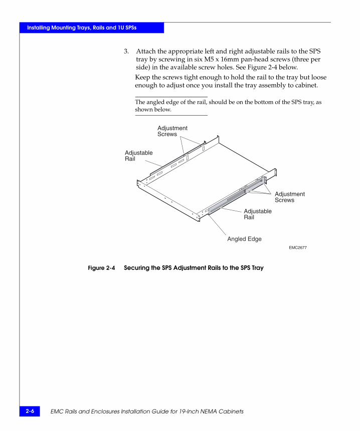
3. Attach the appropriate left and right adjustable rails to the SPS tray by screwing in six M5 x 16mm pan-head screws (three per side) in the available screw holes. See Figure 2-4 below. Keep the screws tight enough to hold the rail to the tray but loose enough to adjust once you install the tray assembly to cabinet.
The angled edge of the rail, should be on the bottom of the SPS tray, as shown below.
Figure 2-4 Securing the SPS Adjustment Rails to the SPS Tray
EMC2677
Angled Edge
AdjustmentScrews
AdjustmentScrews
AdjustableRail
AdjustableRail
Installing Adjustable Rails to the SPS Tray 2-7
Installing Mounting Trays, Rails and 1U SPSs
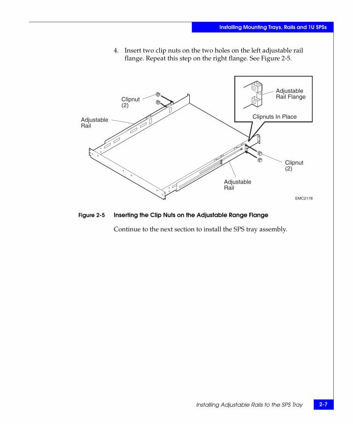
4. Insert two clip nuts on the two holes on the left adjustable rail flange. Repeat this step on the right flange. See Figure 2-5.
Figure 2-5 Inserting the Clip Nuts on the Adjustable Range Flange
Continue to the next section to install the SPS tray assembly.
EMC2178
Clipnuts In Place
AdjustableRail FlangeClipnut
(2)
Clipnut(2)
AdjustableRail
AdjustableRail
2-8 EMC Rails and Enclosures Installation Guide for 19-Inch NEMA Cabinets
Installing Mounting Trays, Rails and 1U SPSs
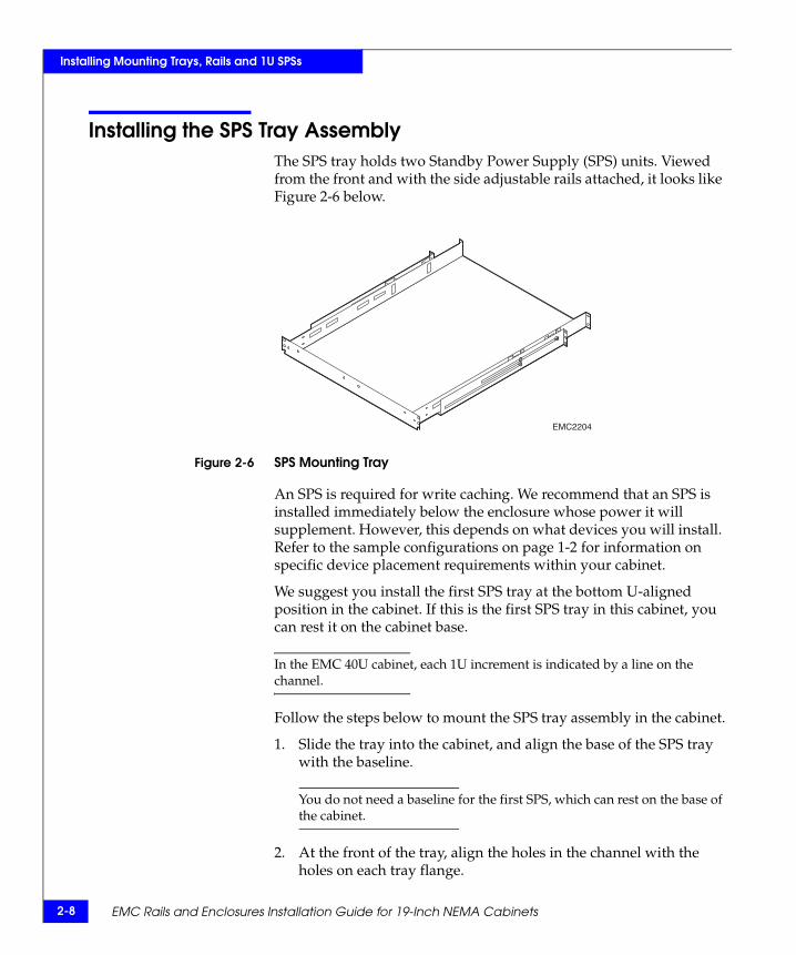
Installing the SPS Tray AssemblyThe SPS tray holds two Standby Power Supply (SPS) units. Viewed from the front and with the side adjustable rails attached, it looks like Figure 2-6 below.
Figure 2-6 SPS Mounting Tray
An SPS is required for write caching. We recommend that an SPS is installed immediately below the enclosure whose power it will supplement. However, this depends on what devices you will install. Refer to the sample configurations on page 1-2 for information on specific device placement requirements within your cabinet.
We suggest you install the first SPS tray at the bottom U-aligned position in the cabinet. If this is the first SPS tray in this cabinet, you can rest it on the cabinet base.
In the EMC 40U cabinet, each 1U increment is indicated by a line on the channel.
Follow the steps below to mount the SPS tray assembly in the cabinet.
1. Slide the tray into the cabinet, and align the base of the SPS tray with the baseline.
You do not need a baseline for the first SPS, which can rest on the base of the cabinet.
2. At the front of the tray, align the holes in the channel with the holes on each tray flange.
EMC2204
Installing the SPS Tray Assembly 2-9
Installing Mounting Trays, Rails and 1U SPSs
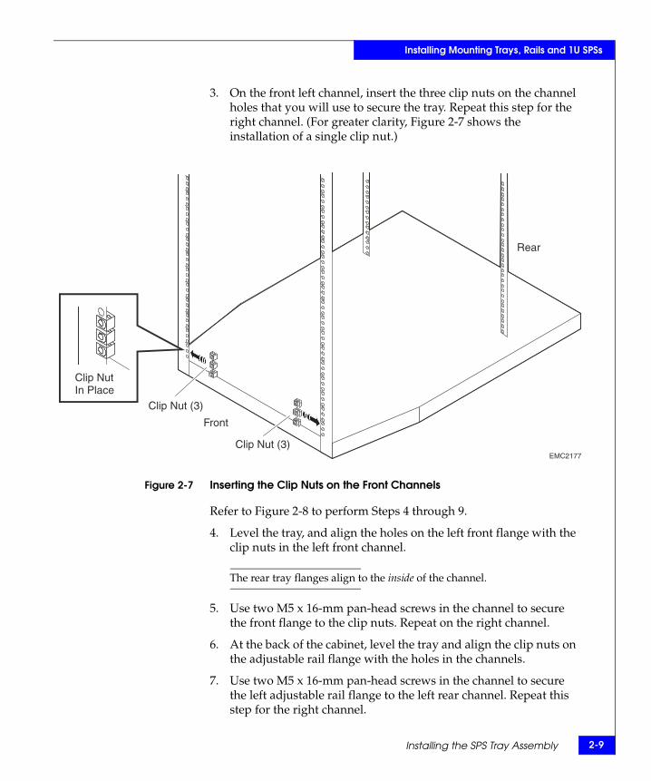
3. On the front left channel, insert the three clip nuts on the channel holes that you will use to secure the tray. Repeat this step for the right channel. (For greater clarity, Figure 2-7 shows the installation of a single clip nut.)
Figure 2-7 Inserting the Clip Nuts on the Front Channels
Refer to Figure 2-8 to perform Steps 4 through 9.
4. Level the tray, and align the holes on the left front flange with the clip nuts in the left front channel.
The rear tray flanges align to the inside of the channel.
5. Use two M5 x 16-mm pan-head screws in the channel to secure the front flange to the clip nuts. Repeat on the right channel.
6. At the back of the cabinet, level the tray and align the clip nuts on the adjustable rail flange with the holes in the channels.
7. Use two M5 x 16-mm pan-head screws in the channel to secure the left adjustable rail flange to the left rear channel. Repeat this step for the right channel.
EMC2177Clip Nut (3)
Clip Nut (3)
Front
Rear
Clip NutIn Place
2-10 EMC Rails and Enclosures Installation Guide for 19-Inch NEMA Cabinets
Installing Mounting Trays, Rails and 1U SPSs
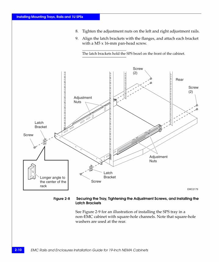
8. Tighten the adjustment nuts on the left and right adjustment rails.
9. Align the latch brackets with the flanges, and attach each bracket with a M5 x 16-mm pan-head screw.
The latch brackets hold the SPS bezel on the front of the cabinet.
Figure 2-8 Securing the Tray, Tightening the Adjustment Screws, and Installing the Latch Brackets
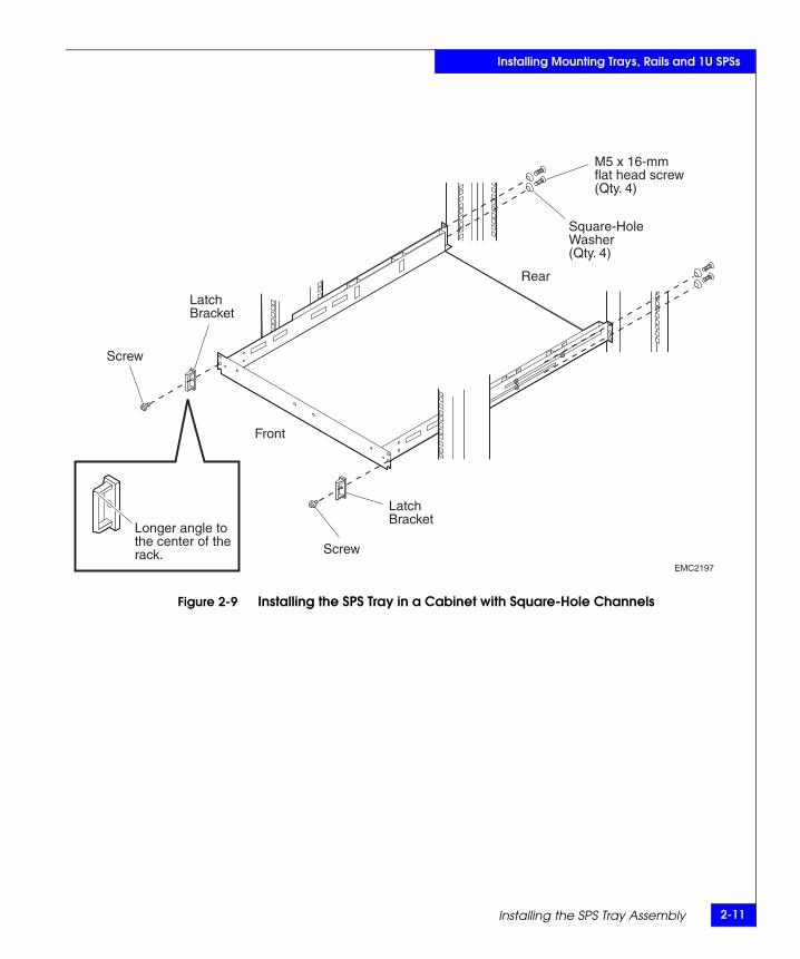
See Figure 2-9 for an illustration of installing the SPS tray in a non-EMC cabinet with square-hole channels. Note that square-hole washers are used at the rear.
EMC2179
Longer angle tothe center of therack
LatchBracket
LatchBracket
Screw
Screw
Screw(2)
Screw(2)
AdjustmentNuts
AdjustmentNuts
Rear
Installing the SPS Tray Assembly 2-11
Installing Mounting Trays, Rails and 1U SPSs
Figure 2-9 Installing the SPS Tray in a Cabinet with Square-Hole Channels
EMC2197
Longer angle tothe center of therack.
Screw
Screw
LatchBracket
LatchBracket
Front
Rear
Square-HoleWasher(Qty. 4)
M5 x 16-mmflat head screw(Qty. 4)
2-12 EMC Rails and Enclosures Installation Guide for 19-Inch NEMA Cabinets
Installing Mounting Trays, Rails and 1U SPSs
Installing an SPS in the TrayThis section explains how to install an SPS in the rackmount tray. See your specific hardware reference manual for information on cabling the SPS.
Install the SPS in the rackmount tray as follows:
1. Remove the SPS from its packaging, and place it on a clean, static-free surface.
Place SPS units directly beneath the enclosure to which they will connect. Refer to your device-specific hardware reference for cabling details.
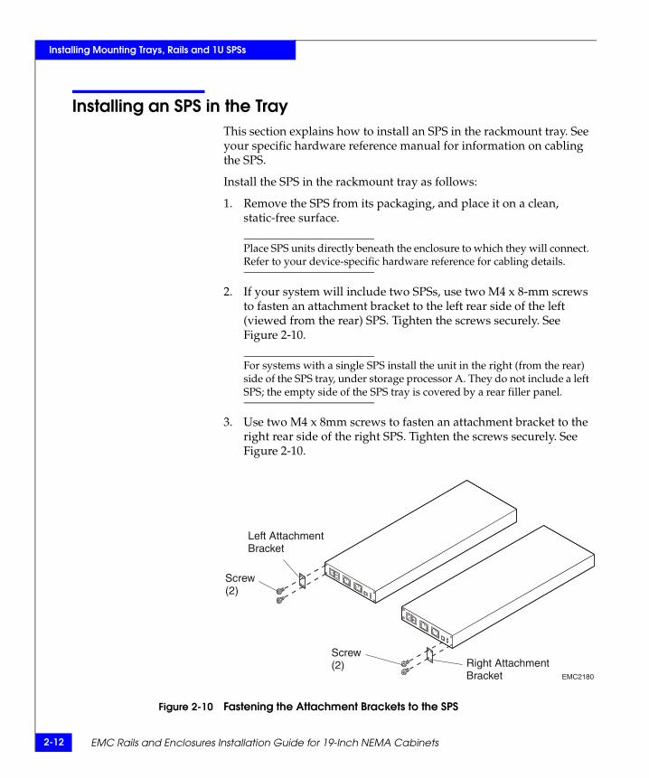
2. If your system will include two SPSs, use two M4 x 8-mm screws to fasten an attachment bracket to the left rear side of the left (viewed from the rear) SPS. Tighten the screws securely. See Figure 2-10.
For systems with a single SPS install the unit in the right (from the rear) side of the SPS tray, under storage processor A. They do not include a left SPS; the empty side of the SPS tray is covered by a rear filler panel.
3. Use two M4 x 8mm screws to fasten an attachment bracket to the right rear side of the right SPS. Tighten the screws securely. See Figure 2-10.
Figure 2-10 Fastening the Attachment Brackets to the SPS
EMC2180
Left AttachmentBracket
Right AttachmentBracket
Screw(2)
Screw(2)
Installing an SPS in the Tray 2-13
Installing Mounting Trays, Rails and 1U SPSs
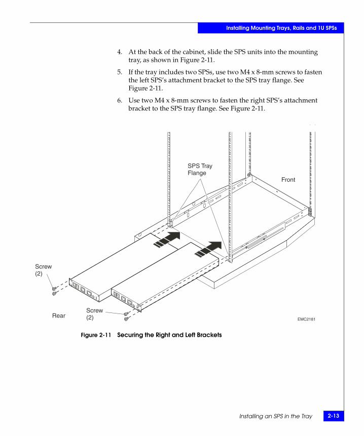
4. At the back of the cabinet, slide the SPS units into the mounting tray, as shown in Figure 2-11.
5. If the tray includes two SPSs, use two M4 x 8-mm screws to fasten the left SPS’s attachment bracket to the SPS tray flange. See Figure 2-11.
6. Use two M4 x 8-mm screws to fasten the right SPS’s attachment bracket to the SPS tray flange. See Figure 2-11.
Figure 2-11 Securing the Right and Left Brackets
EMC2181
Screw(2)
Screw(2)
Front
Rear
SPS TrayFlange
2-14 EMC Rails and Enclosures Installation Guide for 19-Inch NEMA Cabinets
Installing Mounting Trays, Rails and 1U SPSs
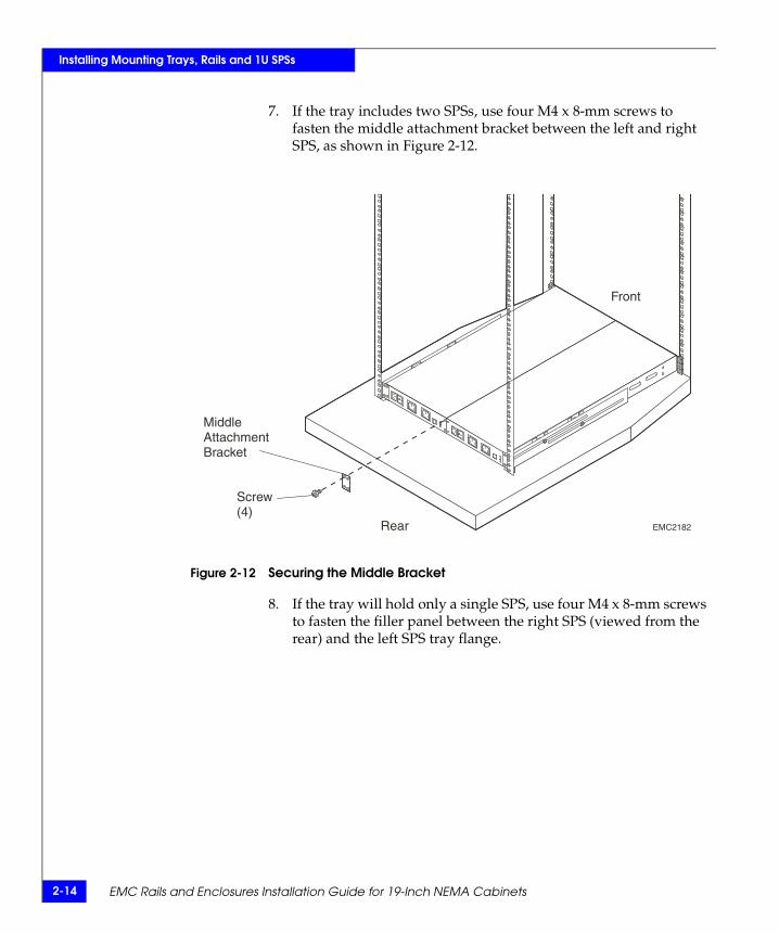
7. If the tray includes two SPSs, use four M4 x 8-mm screws to fasten the middle attachment bracket between the left and right SPS, as shown in Figure 2-12.
Figure 2-12 Securing the Middle Bracket
8. If the tray will hold only a single SPS, use four M4 x 8-mm screws to fasten the filler panel between the right SPS (viewed from the rear) and the left SPS tray flange.
EMC2182
Screw(4)
Front
Rear
MiddleAttachmentBracket
Installing an SPS in the Tray 2-15
Installing Mounting Trays, Rails and 1U SPSs
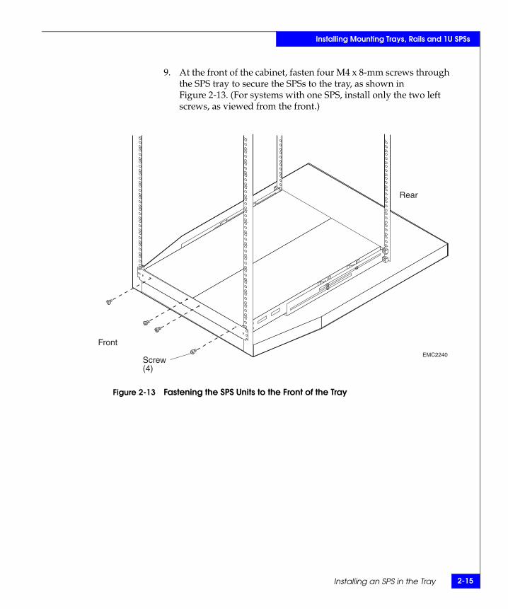
9. At the front of the cabinet, fasten four M4 x 8-mm screws through the SPS tray to secure the SPSs to the tray, as shown in Figure 2-13. (For systems with one SPS, install only the two left screws, as viewed from the front.)
Figure 2-13 Fastening the SPS Units to the Front of the Tray
EMC2240Screw(4)
Front
Rear
2-16 EMC Rails and Enclosures Installation Guide for 19-Inch NEMA Cabinets
Installing Mounting Trays, Rails and 1U SPSs
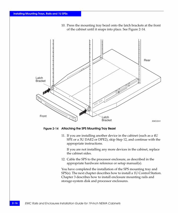
10. Press the mounting tray bezel onto the latch brackets at the front of the cabinet until it snaps into place. See Figure 2-14.
Figure 2-14 Attaching the SPS Mounting Tray Bezel
11. If you are installing another device in the cabinet (such as a 4U SPE or a 3U DAE2 or DPE2), skip Step 12, and continue with the appropriate instructions.
If you are not installing any more devices in the cabinet, replace the cabinet sides.
12. Cable the SPS to the processor enclosure, as described in the appropriate hardware reference or setup manual(s).
You have completed the installation of the SPS mounting tray and SPS(s). The next chapter describes how to install a 1U Control Station. Chapter 3 describes how to install enclosure mounting rails and storage-system disk and processor enclosures.
EMC2241
Front
Rear
LatchBracket
LatchBracket
Installing Mounting Rails and the 1U Control Station Assembly 3-1
3
This chapter discusses the installation of the mounting rails for the 1U Control Station assembly. It also describes the materials you will need for mounting this assembly in the cabinet.
Major topics include
◆ Before You Begin ................................................................................3-2◆ Control Station Mounting Kit ..........................................................3-4◆ Installing Mounting Rails for the Control Station.........................3-5◆ Installing the Control Station Assembly....................................... 3-11
Instructions for adding Fibre Channel switches to an EMC storage system are included in the device-specific documentation that accompanies the switch.
Installing MountingRails and the
1U Control StationAssembly
3-2 EMC Rails and Enclosures Installation Guide for 19-Inch NEMA Cabinets
Installing Mounting Rails and the 1U Control Station Assembly
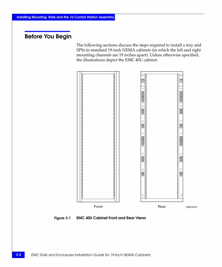
Before You BeginThe following sections discuss the steps required to install a tray and SPSs in standard 19-inch NEMA cabinets (in which the left and right mounting channels are 19 inches apart). Unless otherwise specified, the illustrations depict the EMC 40U cabinet.
Figure 3-1 EMC 40U Cabinet Front and Rear Views
EMC2203Front Rear
Before You Begin 3-3
Installing Mounting Rails and the 1U Control Station Assembly
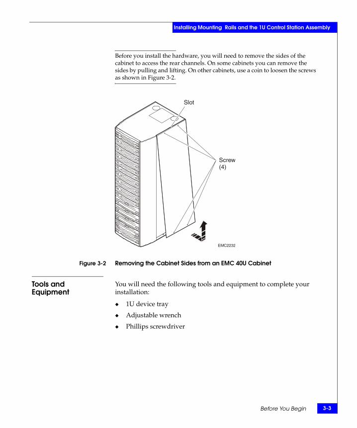
Before you install the hardware, you will need to remove the sides of the cabinet to access the rear channels. On some cabinets you can remove the sides by pulling and lifting. On other cabinets, use a coin to loosen the screws as shown in Figure 3-2.
Figure 3-2 Removing the Cabinet Sides from an EMC 40U Cabinet
Tools and Equipment
You will need the following tools and equipment to complete your installation:
◆ 1U device tray
◆ Adjustable wrench
◆ Phillips screwdriver
EMC2232
Slot
Screw(4)
3-4 EMC Rails and Enclosures Installation Guide for 19-Inch NEMA Cabinets
Installing Mounting Rails and the 1U Control Station Assembly
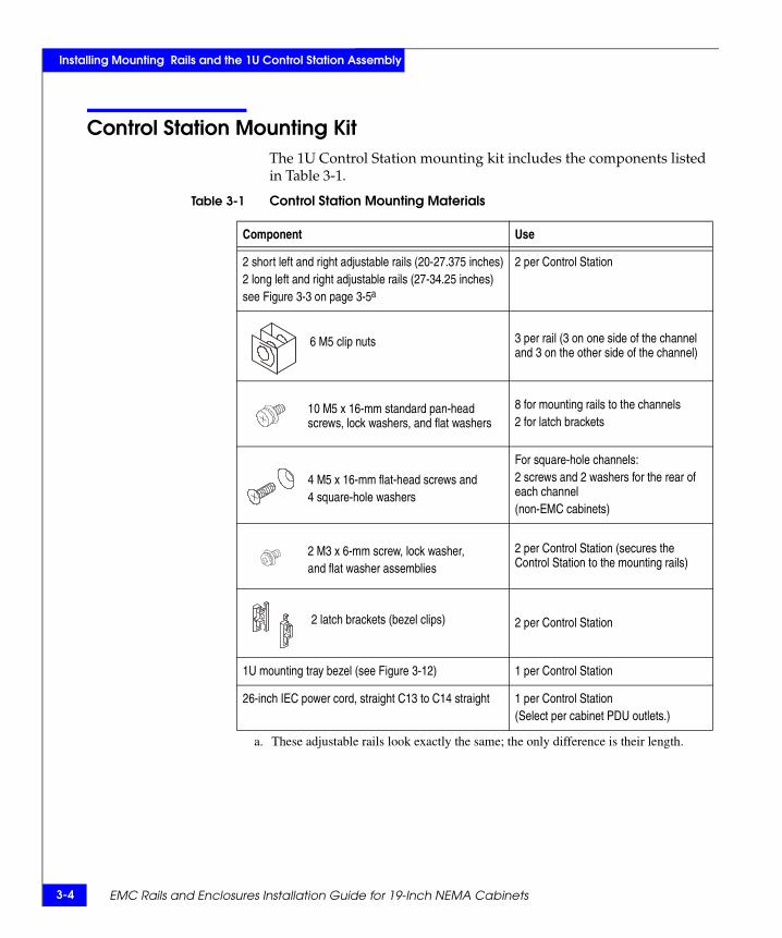
Control Station Mounting KitThe 1U Control Station mounting kit includes the components listed in Table 3-1.
Table 3-1 Control Station Mounting Materials
Component Use
2 short left and right adjustable rails (20-27.375 inches)2 long left and right adjustable rails (27-34.25 inches)see Figure 3-3 on page 3-5a
a. These adjustable rails look exactly the same; the only difference is their length.
2 per Control Station
6 M5 clip nuts 3 per rail (3 on one side of the channel and 3 on the other side of the channel)
10 M5 x 16-mm standard pan-head screws, lock washers, and flat washers
8 for mounting rails to the channels2 for latch brackets
4 M5 x 16-mm flat-head screws and4 square-hole washers
For square-hole channels:2 screws and 2 washers for the rear of each channel(non-EMC cabinets)
2 M3 x 6-mm screw, lock washer,and flat washer assemblies
2 per Control Station (secures the Control Station to the mounting rails)
2 latch brackets (bezel clips) 2 per Control Station
1U mounting tray bezel (see Figure 3-12) 1 per Control Station
26-inch IEC power cord, straight C13 to C14 straight 1 per Control Station(Select per cabinet PDU outlets.)
Installing Mounting Rails for the Control Station 3-5
Installing Mounting Rails and the 1U Control Station Assembly
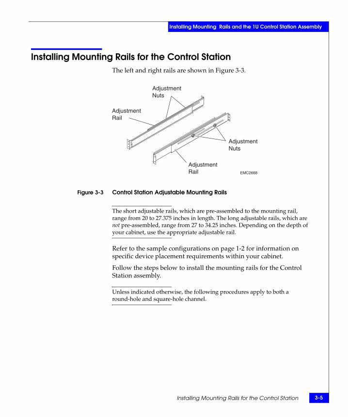
Installing Mounting Rails for the Control Station The left and right rails are shown in Figure 3-3.
Figure 3-3 Control Station Adjustable Mounting Rails
The short adjustable rails, which are pre-assembled to the mounting rail, range from 20 to 27.375 inches in length. The long adjustable rails, which are not pre-assembled, range from 27 to 34.25 inches. Depending on the depth of your cabinet, use the appropriate adjustable rail.
Refer to the sample configurations on page 1-2 for information on specific device placement requirements within your cabinet.
Follow the steps below to install the mounting rails for the Control Station assembly.
Unless indicated otherwise, the following procedures apply to both a round-hole and square-hole channel.
AdjustmentRail
AdjustmentNuts
AdjustmentRail
AdjustmentNuts
EMC2668

3-6 EMC Rails and Enclosures Installation Guide for 19-Inch NEMA Cabinets
Installing Mounting Rails and the 1U Control Station Assembly
1. Insert six clip nuts (three per side) over the appropriate front channel holes, as shown in Figure 3-3. These clip nuts secure the mounting rails to the front channel.
Figure 3-4 Installing Clip Nuts for Securing Mounting Rails to Cabinet Channels
2. Carefully measure the distance between the inside edge of the front channel and the inside edge of the rear channel.
3. The shorter rails, which range from 20 to 27.375 inches, are pre-assembled to the mounting rail. If you need to use the longer adjustable rails, which range from 27 to 34.25 inches, do the following:
EMC2663
Clip Nut (3)
Clip Nut (3)
Front
Clip Nutsin Place
Baseline

Installing Mounting Rails for the Control Station 3-7
Installing Mounting Rails and the 1U Control Station Assembly
a. Remove the short adjustable rails by unscrewing the adjustment nuts, as shown in Figure 3-5.
Figure 3-5 Removing/Installing the Adjustable Rails
b. Secure the long adjustable rails to the mounting rails using the adjustment nuts, as shown in Figure 3-5.
4. Loosen the two adjustment nuts on each rail and extend the rails to the correct length for the distance between the front and rear channels. Tighten the nuts finger tight. See Figure 3-6.
Figure 3-6 Adjusting Rail Length
5. Align the front rail flanges over the three nut clips.
AdjustableRail
AdjustmentNuts
AdjustmentPosts
EMC2680
AdjustmentRail
AdjustmentNuts
AdjustmentRail
AdjustmentNuts
EMC2668
3-8 EMC Rails and Enclosures Installation Guide for 19-Inch NEMA Cabinets
Installing Mounting Rails and the 1U Control Station Assembly
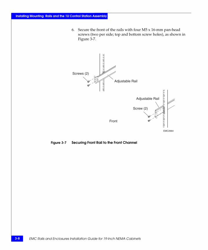
6. Secure the front of the rails with four M5 x 16-mm pan-head screws (two per side; top and bottom screw holes), as shown in Figure 3-7.
Figure 3-7 Securing Front Rail to the Front Channel
EMC2664
Screws (2)
Screw (2)
Adjustable Rail
Adjustable Rail
Front

Installing Mounting Rails for the Control Station 3-9
Installing Mounting Rails and the 1U Control Station Assembly
7. Secure the rear rail flanges to the inside of the rear channel, using four M5 x 16-mm pan-head screws (two per side), as shown in Figure 3-8.
Figure 3-8 Securing Rear Rail to the Rear Round-Hole Channel
EMC2665
Screw (2)
Adjustable Rail
Adjustable Rail
Screw (2)
Rear
3-10 EMC Rails and Enclosures Installation Guide for 19-Inch NEMA Cabinets
Installing Mounting Rails and the 1U Control Station Assembly
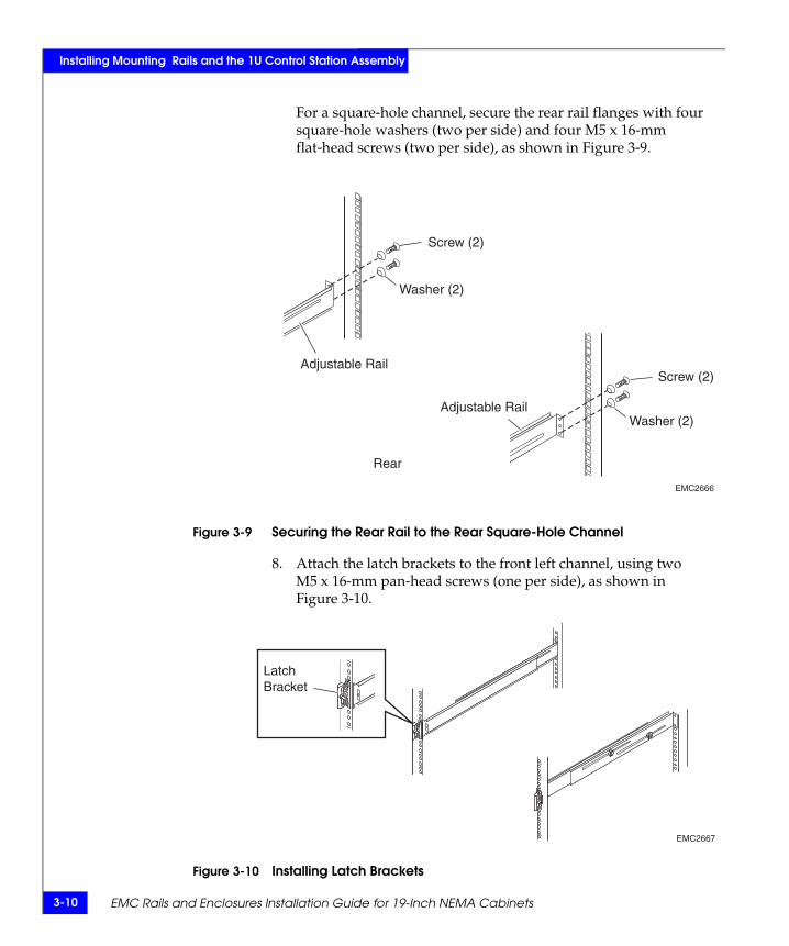
For a square-hole channel, secure the rear rail flanges with four square-hole washers (two per side) and four M5 x 16-mm flat-head screws (two per side), as shown in Figure 3-9.
Figure 3-9 Securing the Rear Rail to the Rear Square-Hole Channel
8. Attach the latch brackets to the front left channel, using two M5 x 16-mm pan-head screws (one per side), as shown in Figure 3-10.
Figure 3-10 Installing Latch Brackets
Screw (2)
Adjustable Rail
Adjustable Rail
Screw (2)
EMC2666
Washer (2)
Washer (2)
Rear
LatchBracket
EMC2667
Installing the Control Station Assembly 3-11
Installing Mounting Rails and the 1U Control Station Assembly
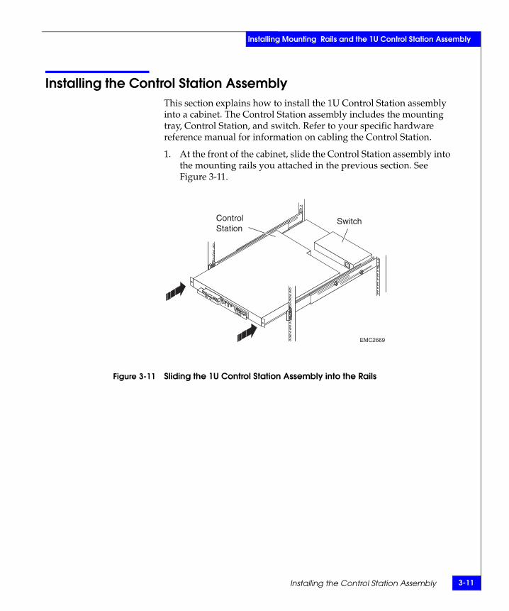
Installing the Control Station AssemblyThis section explains how to install the 1U Control Station assembly into a cabinet. The Control Station assembly includes the mounting tray, Control Station, and switch. Refer to your specific hardware reference manual for information on cabling the Control Station.
1. At the front of the cabinet, slide the Control Station assembly into the mounting rails you attached in the previous section. See Figure 3-11.
Figure 3-11 Sliding the 1U Control Station Assembly into the Rails
EMC2669
SwitchControlStation
3-12 EMC Rails and Enclosures Installation Guide for 19-Inch NEMA Cabinets
Installing Mounting Rails and the 1U Control Station Assembly
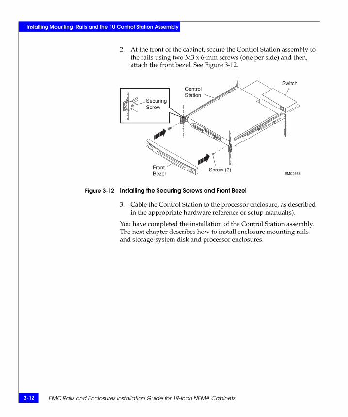
2. At the front of the cabinet, secure the Control Station assembly to the rails using two M3 x 6-mm screws (one per side) and then, attach the front bezel. See Figure 3-12.
Figure 3-12 Installing the Securing Screws and Front Bezel
3. Cable the Control Station to the processor enclosure, as described in the appropriate hardware reference or setup manual(s).
You have completed the installation of the Control Station assembly. The next chapter describes how to install enclosure mounting rails and storage-system disk and processor enclosures.
SecuringScrew
EMC2658Screw (2)Front
Bezel
SwitchControlStation

Installing Mounting Rails and 3U and 4U Enclosures 4-1
4
This chapter discusses the installation of mounting rails and 3U and 4U enclosures in standard 19-inch NEMA cabinets (in which the left and right mounting channels are 19 inches apart).
Major topics include
◆ Before You Begin ................................................................................4-2◆ 3U and 4U Mounting Kits.................................................................4-4◆ Installing the Mounting Rails...........................................................4-5◆ Installing a 4U Enclosure in the Cabinet ......................................4-12◆ Installing a 3U Enclosure in the Cabinet ......................................4-18
Since EMC uses easily adjustable "universal" rails to mount these items in a NEMA-standard cabinet, the instructions in this chapter apply to non-EMC cabinets as well.
InstallingMounting Rails and 3U
and 4U Enclosures
4-2 EMC Rails and Enclosures Installation Guide for 19-Inch NEMA Cabinets
Installing Mounting Rails and 3U and 4U Enclosures
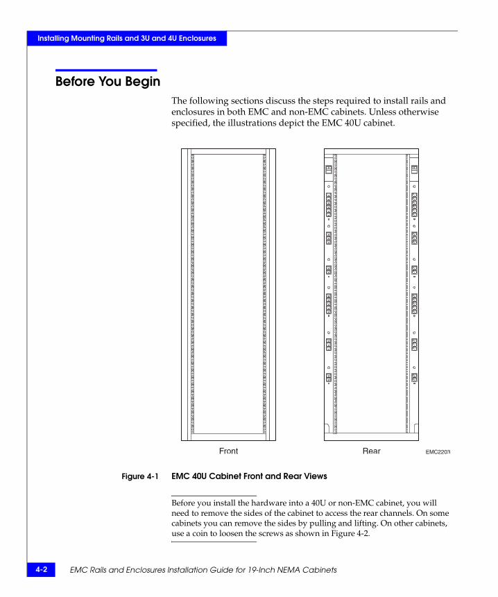
Before You BeginThe following sections discuss the steps required to install rails and enclosures in both EMC and non-EMC cabinets. Unless otherwise specified, the illustrations depict the EMC 40U cabinet.
Figure 4-1 EMC 40U Cabinet Front and Rear Views
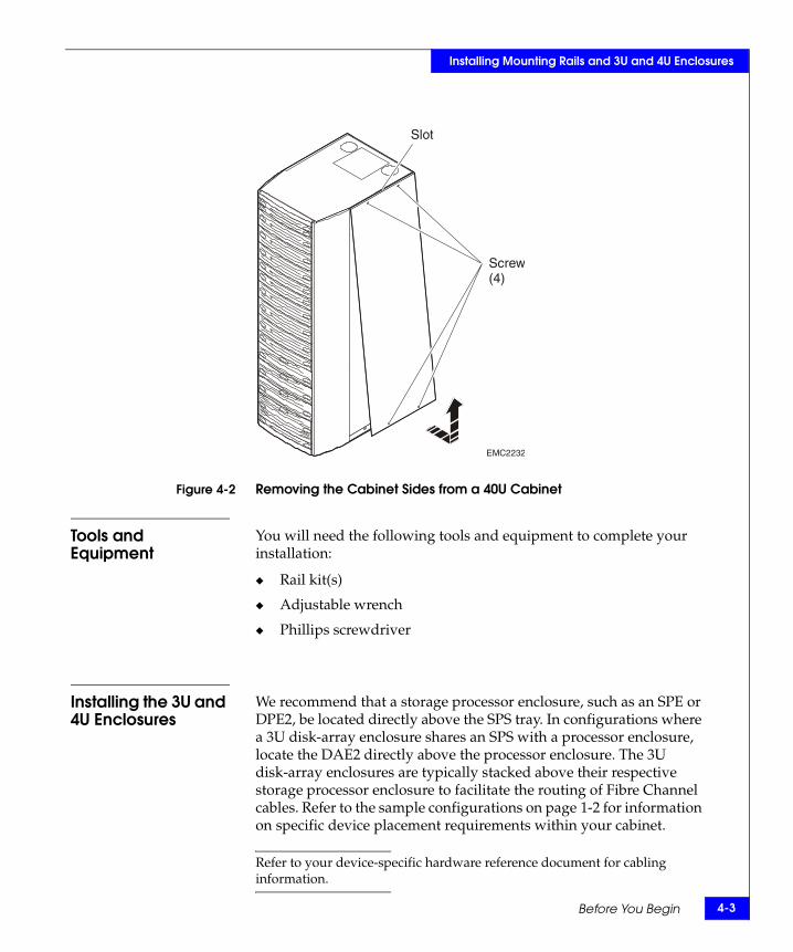
Before you install the hardware into a 40U or non-EMC cabinet, you will need to remove the sides of the cabinet to access the rear channels. On some cabinets you can remove the sides by pulling and lifting. On other cabinets, use a coin to loosen the screws as shown in Figure 4-2.
EMC2203Front Rear
Before You Begin 4-3
Installing Mounting Rails and 3U and 4U Enclosures
Figure 4-2 Removing the Cabinet Sides from a 40U Cabinet
Tools and Equipment
You will need the following tools and equipment to complete your installation:
◆ Rail kit(s)
◆ Adjustable wrench
◆ Phillips screwdriver
Installing the 3U and 4U Enclosures
We recommend that a storage processor enclosure, such as an SPE or DPE2, be located directly above the SPS tray. In configurations where a 3U disk-array enclosure shares an SPS with a processor enclosure, locate the DAE2 directly above the processor enclosure. The 3U disk-array enclosures are typically stacked above their respective storage processor enclosure to facilitate the routing of Fibre Channel cables. Refer to the sample configurations on page 1-2 for information on specific device placement requirements within your cabinet.
Refer to your device-specific hardware reference document for cabling information.
EMC2232
Slot
Screw(4)
4-4 EMC Rails and Enclosures Installation Guide for 19-Inch NEMA Cabinets
Installing Mounting Rails and 3U and 4U Enclosures
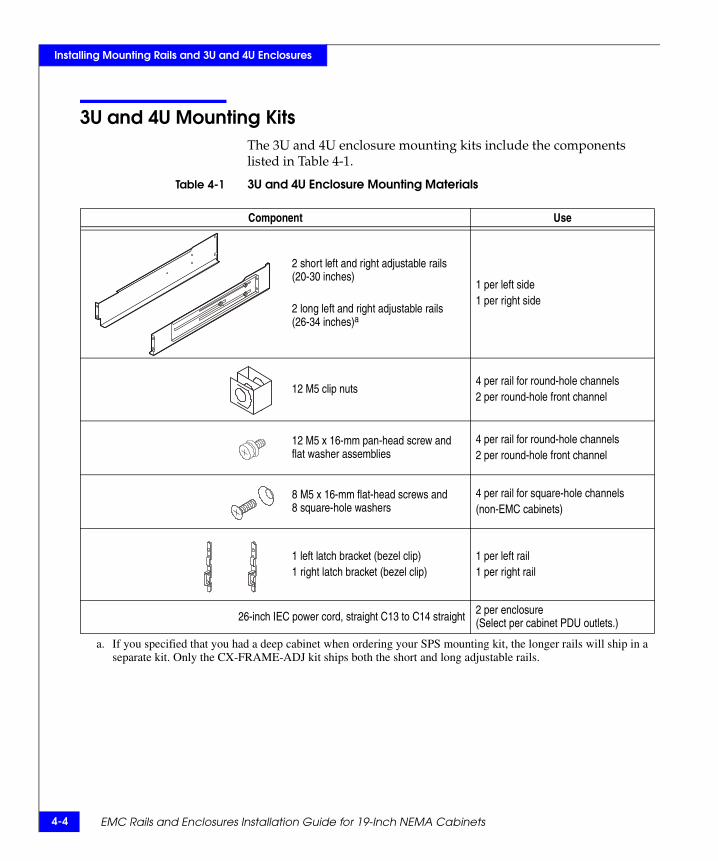
3U and 4U Mounting KitsThe 3U and 4U enclosure mounting kits include the components listed in Table 4-1.
Table 4-1 3U and 4U Enclosure Mounting Materials
Component Use
2 short left and right adjustable rails (20-30 inches)
2 long left and right adjustable rails (26-34 inches)a
a. If you specified that you had a deep cabinet when ordering your SPS mounting kit, the longer rails will ship in a separate kit. Only the CX-FRAME-ADJ kit ships both the short and long adjustable rails.
1 per left side1 per right side
12 M5 clip nuts4 per rail for round-hole channels2 per round-hole front channel
12 M5 x 16-mm pan-head screw and flat washer assemblies
4 per rail for round-hole channels2 per round-hole front channel
8 M5 x 16-mm flat-head screws and 8 square-hole washers
4 per rail for square-hole channels(non-EMC cabinets)
1 left latch bracket (bezel clip)1 right latch bracket (bezel clip)
1 per left rail1 per right rail
26-inch IEC power cord, straight C13 to C14 straight 2 per enclosure(Select per cabinet PDU outlets.)
Installing the Mounting Rails 4-5
Installing Mounting Rails and 3U and 4U Enclosures
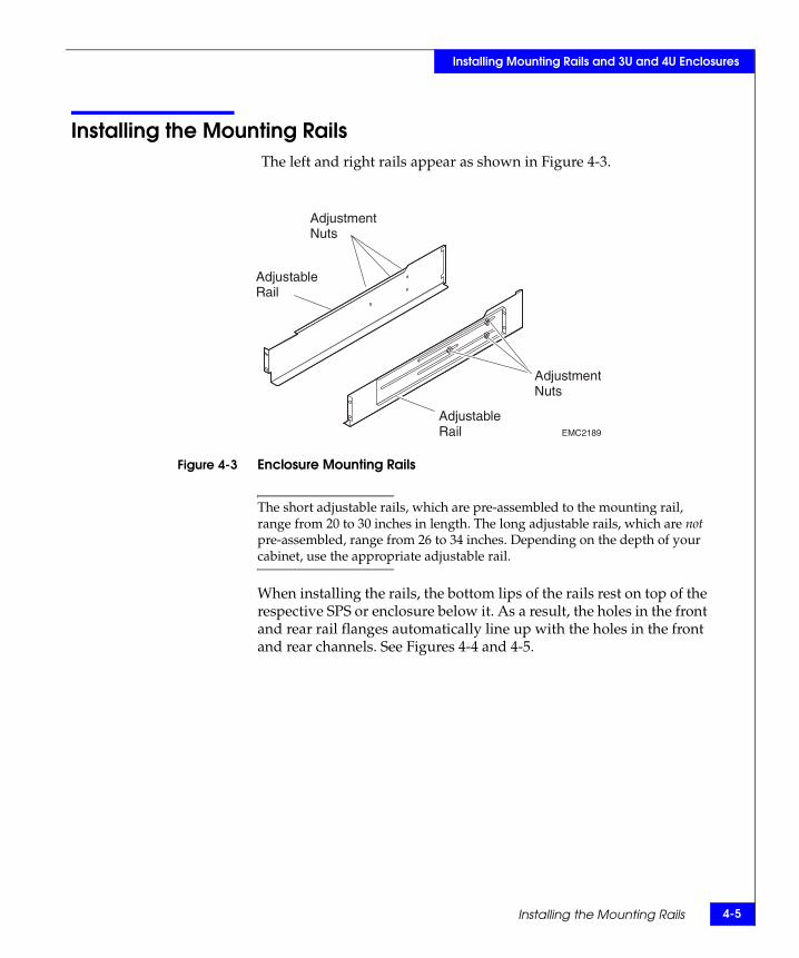
Installing the Mounting Rails The left and right rails appear as shown in Figure 4-3.
Figure 4-3 Enclosure Mounting Rails
The short adjustable rails, which are pre-assembled to the mounting rail, range from 20 to 30 inches in length. The long adjustable rails, which are not pre-assembled, range from 26 to 34 inches. Depending on the depth of your cabinet, use the appropriate adjustable rail.
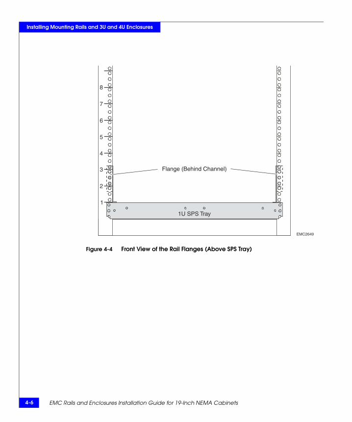
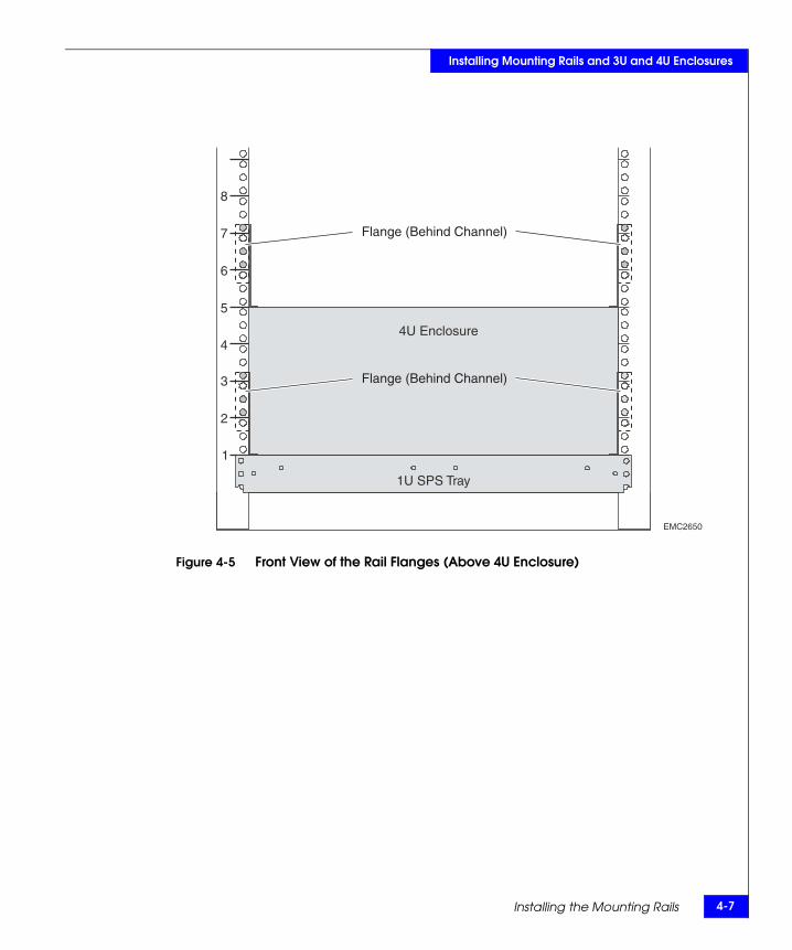
When installing the rails, the bottom lips of the rails rest on top of the respective SPS or enclosure below it. As a result, the holes in the front and rear rail flanges automatically line up with the holes in the front and rear channels. See Figures 4-4 and 4-5.
EMC2189
AdjustableRail
AdjustableRail
AdjustmentNuts
AdjustmentNuts
4-6 EMC Rails and Enclosures Installation Guide for 19-Inch NEMA Cabinets
Installing Mounting Rails and 3U and 4U Enclosures
Figure 4-4 Front View of the Rail Flanges (Above SPS Tray)
EMC2649
1
2
3
4
5
6
7
8
1U SPS Tray
Flange (Behind Channel)
Installing the Mounting Rails 4-7
Installing Mounting Rails and 3U and 4U Enclosures
Figure 4-5 Front View of the Rail Flanges (Above 4U Enclosure)
EMC2650
4U Enclosure
1
2
3
4
5
6
7
8
1U SPS Tray
Flange (Behind Channel)
Flange (Behind Channel)
4-8 EMC Rails and Enclosures Installation Guide for 19-Inch NEMA Cabinets
Installing Mounting Rails and 3U and 4U Enclosures
Follow the steps below to install the mounting rails.
1. Carefully measure the distance between the inside edge of the front channel and the inside edge of the rear channel.
The front and rear rail flanges attach to the inside of the channels.
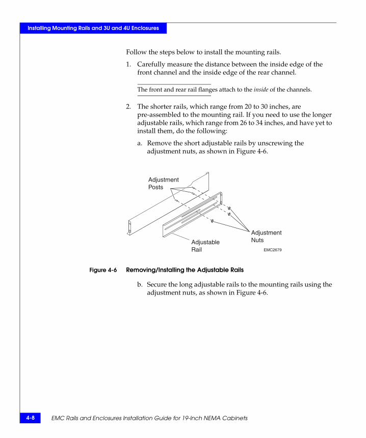
2. The shorter rails, which range from 20 to 30 inches, are pre-assembled to the mounting rail. If you need to use the longer adjustable rails, which range from 26 to 34 inches, and have yet to install them, do the following:
a. Remove the short adjustable rails by unscrewing the adjustment nuts, as shown in Figure 4-6.
Figure 4-6 Removing/Installing the Adjustable Rails
b. Secure the long adjustable rails to the mounting rails using the adjustment nuts, as shown in Figure 4-6.
EMC2679
AdjustableRail
AdjustmentNuts
AdjustmentPosts
Installing the Mounting Rails 4-9
Installing Mounting Rails and 3U and 4U Enclosures
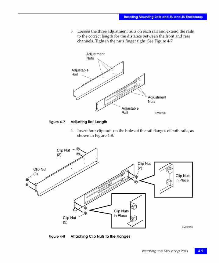
3. Loosen the three adjustment nuts on each rail and extend the rails to the correct length for the distance between the front and rear channels. Tighten the nuts finger tight. See Figure 4-7.
Figure 4-7 Adjusting Rail Length
4. Insert four clip nuts on the holes of the rail flanges of both rails, as shown in Figure 4-8.
Figure 4-8 Attaching Clip Nuts to the Flanges
EMC2189
AdjustableRail
AdjustableRail
AdjustmentNuts
AdjustmentNuts
EMC2653
Clip Nutsin Place
Clip Nutsin Place
Clip Nut(2)
Clip Nut(2)
Clip Nut(2)
Clip Nut(2)
4-10 EMC Rails and Enclosures Installation Guide for 19-Inch NEMA Cabinets
Installing Mounting Rails and 3U and 4U Enclosures
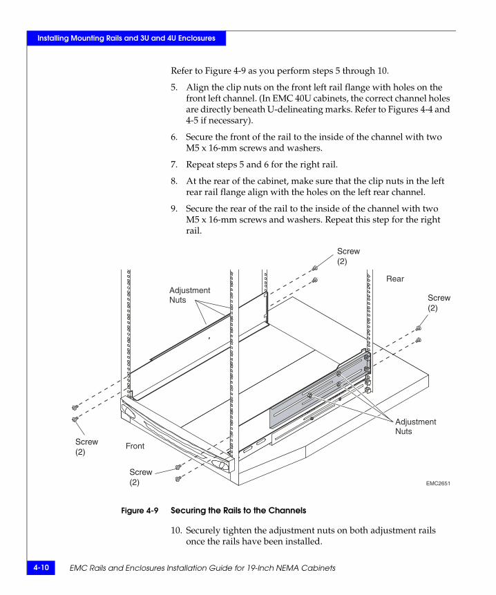
Refer to Figure 4-9 as you perform steps 5 through 10.
5. Align the clip nuts on the front left rail flange with holes on the front left channel. (In EMC 40U cabinets, the correct channel holes are directly beneath U-delineating marks. Refer to Figures 4-4 and 4-5 if necessary).
6. Secure the front of the rail to the inside of the channel with two M5 x 16-mm screws and washers.
7. Repeat steps 5 and 6 for the right rail.
8. At the rear of the cabinet, make sure that the clip nuts in the left rear rail flange align with the holes on the left rear channel.
9. Secure the rear of the rail to the inside of the channel with two M5 x 16-mm screws and washers. Repeat this step for the right rail.
Figure 4-9 Securing the Rails to the Channels
10. Securely tighten the adjustment nuts on both adjustment rails once the rails have been installed.
EMC2651
AdjustmentNuts
Front
Rear
AdjustmentNuts
Screw(2)
Screw(2)
Screw(2)
Screw(2)

Installing the Mounting Rails 4-11
Installing Mounting Rails and 3U and 4U Enclosures
11. Insert four clip nuts over the appropriate front channel holes for the enclosure you are installing. Refer to Figure 4-10. You will use these nuts to secure the enclosure to the front channels, after you install the enclosure in the cabinet.
Figure 4-10 Installing Clip Nuts to Secure Enclosures to Cabinet Channels
If you are installing a 4U enclosure (for example, an EMC SPE), continue with the next section.
If you are installing a 3U enclosure (for example, an EMC DPE2, or a DAE2), skip the next section and continue with Installing a 3U Enclosure in the Cabinet on page 4-18.
EMC2648
4U Enclosure
3U Enclosure
1
2
3
4
5
6
7
8
1U SPS Tray
Clip Nuts for:

4-12 EMC Rails and Enclosures Installation Guide for 19-Inch NEMA Cabinets
Installing Mounting Rails and 3U and 4U Enclosures
Installing a 4U Enclosure in the Cabinet
WARNING
The enclosure is heavy and should be installed into a rack by two people. To avoid personal injury and/or damage to the equipment, do not attempt to lift and install the enclosure into a rack without a mechanical lift and/or help from another person.
L’armoire étant lourde, sa mise en place sur une rampe nécessite deux personnes. Afin de ne pas vous blesser et/ou endommager le matériel, n’essayez pas de soulever et d’installer l’armoire sur une rampe sans avoir recours à un relevage mécanique et/ou à l’aide d’une autre personne.
Das Gehäuse ist schwer und sollte nur von zwei Personen in einem Rack installiert werden. Zur Vermeidung von körperlichen Verletzungen und/oder der Beschädigung des Gerätes, bitte das Gehäuse nicht ohne die Hilfe einer zweiten Person anheben und einbauen.
Il contenitore è pesante e dev'essere installato nel rack da due persone. Per evitare danni personali e/o all’apparecchiatura, non tentare di sollevare ed installare in un rack il contenitore senza un sollevatore meccanico e/o l’aiuto di un’altra persona.
Debido a su considerable peso, la instalación del compartimento en el bastidor deben realizarla siempre dos personas. Para evitar daños personales o en el equipo, el compartimento no debe levantarse ni instalarse en el bastidor sin la ayuda de un elevador mecánico o de otra persona.
Refer to the sample configurations on page 1-2 for information on specific device placement requirements within your cabinet.
Installing a 4U Enclosure in the Cabinet 4-13
Installing Mounting Rails and 3U and 4U Enclosures
1. Attach the clip of the ESD wristband (strap) to bare metal on the cabinet, and put the wristband around your wrist with the metal button against your skin.
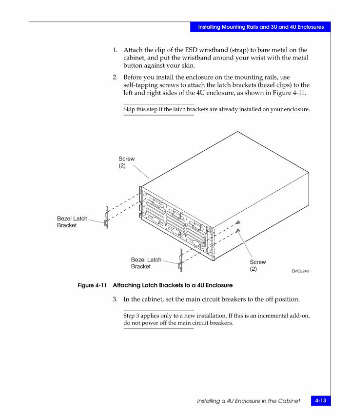
2. Before you install the enclosure on the mounting rails, use self-tapping screws to attach the latch brackets (bezel clips) to the left and right sides of the 4U enclosure, as shown in Figure 4-11.
Skip this step if the latch brackets are already installed on your enclosure.
Figure 4-11 Attaching Latch Brackets to a 4U Enclosure
3. In the cabinet, set the main circuit breakers to the off position.
Step 3 applies only to a new installation. If this is an incremental add-on, do not power off the main circuit breakers.
EMC2243
Bezel LatchBracket
Bezel LatchBracket
Screw(2)
Screw(2)

4-14 EMC Rails and Enclosures Installation Guide for 19-Inch NEMA Cabinets
Installing Mounting Rails and 3U and 4U Enclosures
4. With help from another person, lift the enclosure and, from the front of the cabinet, slide the enclosure onto the appropriate rails as shown in Figure 4-12.
Figure 4-12 Sliding the 4U Enclosure onto the Mounting Rails
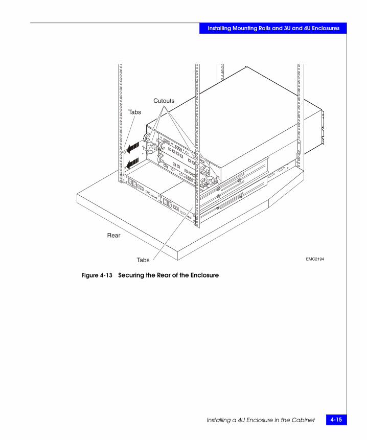
When the enclosure slides to the back of the cabinet, the two cutouts on the corners of the rear of the enclosure insert into the rear tabs on the back corner of each rail. The tabs secure and support the rear of the enclosure. See Figure 4-13.
EMC2244Front
Rear
Installing a 4U Enclosure in the Cabinet 4-15
Installing Mounting Rails and 3U and 4U Enclosures
Figure 4-13 Securing the Rear of the Enclosure
EMC2194
Cutouts
Tabs
Tabs
Rear
4-16 EMC Rails and Enclosures Installation Guide for 19-Inch NEMA Cabinets
Installing Mounting Rails and 3U and 4U Enclosures
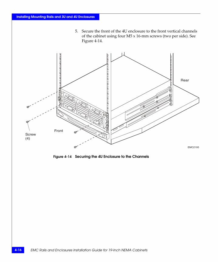
5. Secure the front of the 4U enclosure to the front vertical channels of the cabinet using four M5 x 16-mm screws (two per side). See Figure 4-14.
Figure 4-14 Securing the 4U Enclosure to the Channels
EMC2193
Screw(4)
Front
Rear
Installing a 4U Enclosure in the Cabinet 4-17
Installing Mounting Rails and 3U and 4U Enclosures
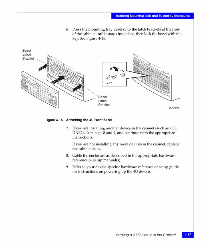
6. Press the mounting tray bezel onto the latch brackets at the front of the cabinet until it snaps into place, then lock the bezel with the key. See Figure 4-15.
Figure 4-15 Attaching the 4U Front Bezel
7. If you are installing another device in the cabinet (such as a 3U DAE2), skip steps 8 and 9, and continue with the appropriate instructions.
If you are not installing any more devices in the cabinet, replace the cabinet sides.
8. Cable the enclosure as described in the appropriate hardware reference or setup manual(s).
9. Refer to your device-specific hardware reference or setup guide for instructions on powering up the 4U device.
EMC1965
BezelLatchBracket
BezelLatchBracket
4-18 EMC Rails and Enclosures Installation Guide for 19-Inch NEMA Cabinets
Installing Mounting Rails and 3U and 4U Enclosures
Installing a 3U Enclosure in the Cabinet
WARNING
The enclosure is heavy and should be installed into a rack by two people. To avoid personal injury and/or damage to the equipment, do not attempt to lift and install the enclosure into a rack without a mechanical lift and/or help from another person.
L’armoire étant lourde, sa mise en place sur une rampe nécessite deux personnes. Afin de ne pas vous blesser et/ou endommager le matériel, n’essayez pas de soulever et d’installer l’armoire sur une rampe sans avoir recours à un relevage mécanique et/ou à l’aide d’une autre personne.
Das Gehäuse ist schwer und sollte nur von zwei Personen in einem Rack installiert werden. Zur Vermeidung von körperlichen Verletzungen und/oder der Beschädigung des Gerätes, bitte das Gehäuse nicht ohne die Hilfe einer zweiten Person anheben und einbauen.
Il contenitore è pesante e dev'essere installato nel rack da due persone. Per evitare danni personali e/o all’apparecchiatura, non tentare di sollevare ed installare in un rack il contenitore senza un sollevatore meccanico e/o l’aiuto di un’altra persona.
Debido a su considerable peso, la instalación del compartimento en el bastidor deben realizarla siempre dos personas. Para evitar daños personales o en el equipo, el compartimento no debe levantarse ni instalarse en el bastidor sin la ayuda de un elevador mecánico o de otra persona.
CAUTION!In DPE2 and some DAE2 configurations, disk modules in slots 0-3 provide mirrored boot capability and are preloaded according to their slot assignment before shipment. Do not move a preloaded module from its assigned slot to another slot, and remove it only to replace the disk.
Installing a 3U Enclosure in the Cabinet 4-19
Installing Mounting Rails and 3U and 4U Enclosures
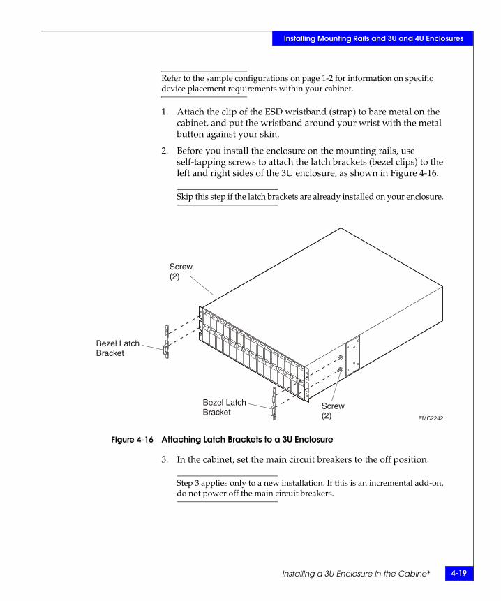
Refer to the sample configurations on page 1-2 for information on specific device placement requirements within your cabinet.
1. Attach the clip of the ESD wristband (strap) to bare metal on the cabinet, and put the wristband around your wrist with the metal button against your skin.
2. Before you install the enclosure on the mounting rails, use self-tapping screws to attach the latch brackets (bezel clips) to the left and right sides of the 3U enclosure, as shown in Figure 4-16.
Skip this step if the latch brackets are already installed on your enclosure.
Figure 4-16 Attaching Latch Brackets to a 3U Enclosure
3. In the cabinet, set the main circuit breakers to the off position.
Step 3 applies only to a new installation. If this is an incremental add-on, do not power off the main circuit breakers.
EMC2242
Bezel LatchBracket
Bezel LatchBracket
Screw(2)
Screw(2)
4-20 EMC Rails and Enclosures Installation Guide for 19-Inch NEMA Cabinets
Installing Mounting Rails and 3U and 4U Enclosures
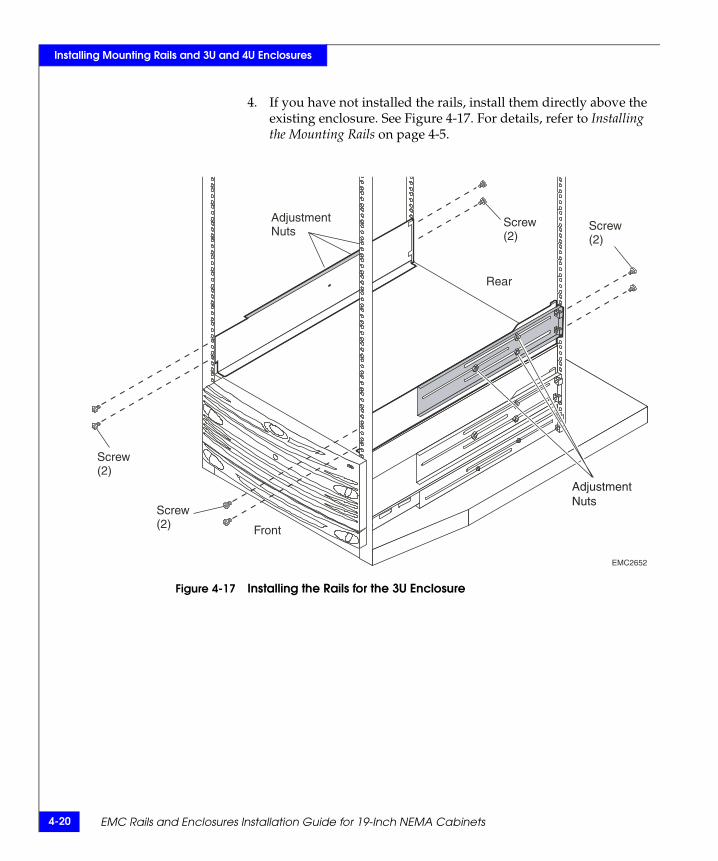
4. If you have not installed the rails, install them directly above the existing enclosure. See Figure 4-17. For details, refer to Installing the Mounting Rails on page 4-5.
Figure 4-17 Installing the Rails for the 3U Enclosure
AdjustmentNuts
EMC2652
Screw(2)
Screw(2)
Rear
Screw(2)
Screw(2)
Front
AdjustmentNuts

Installing a 3U Enclosure in the Cabinet 4-21
Installing Mounting Rails and 3U and 4U Enclosures
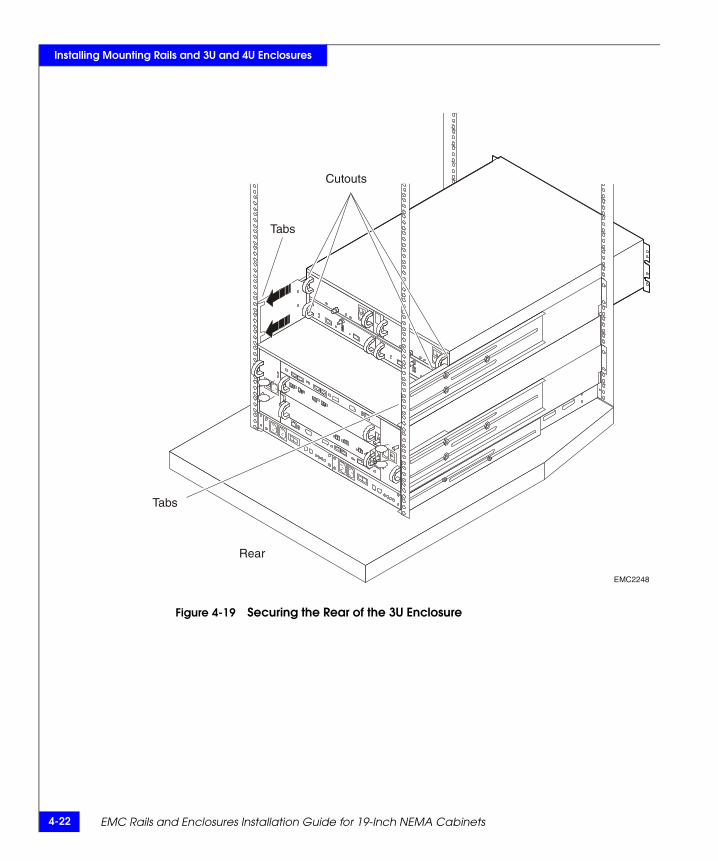
5. With help from another person, lift the enclosure and, from the front of the cabinet, slide the enclosure onto the appropriate rails as shown in Figure 4-18.
Figure 4-18 Sliding the 3U Enclosure onto the Mounting Rails
When the enclosure slides to the back of the cabinet, the two cutouts on the corners of the rear of the enclosure insert into the rear tabs on the back corner of each rail. The tabs secure and support the rear of the enclosure. See Figure 4-19.
EMC2247
Rear
Front
4-22 EMC Rails and Enclosures Installation Guide for 19-Inch NEMA Cabinets
Installing Mounting Rails and 3U and 4U Enclosures
Figure 4-19 Securing the Rear of the 3U Enclosure
EMC2248
Cutouts
Tabs
Tabs
Rear
Installing a 3U Enclosure in the Cabinet 4-23
Installing Mounting Rails and 3U and 4U Enclosures
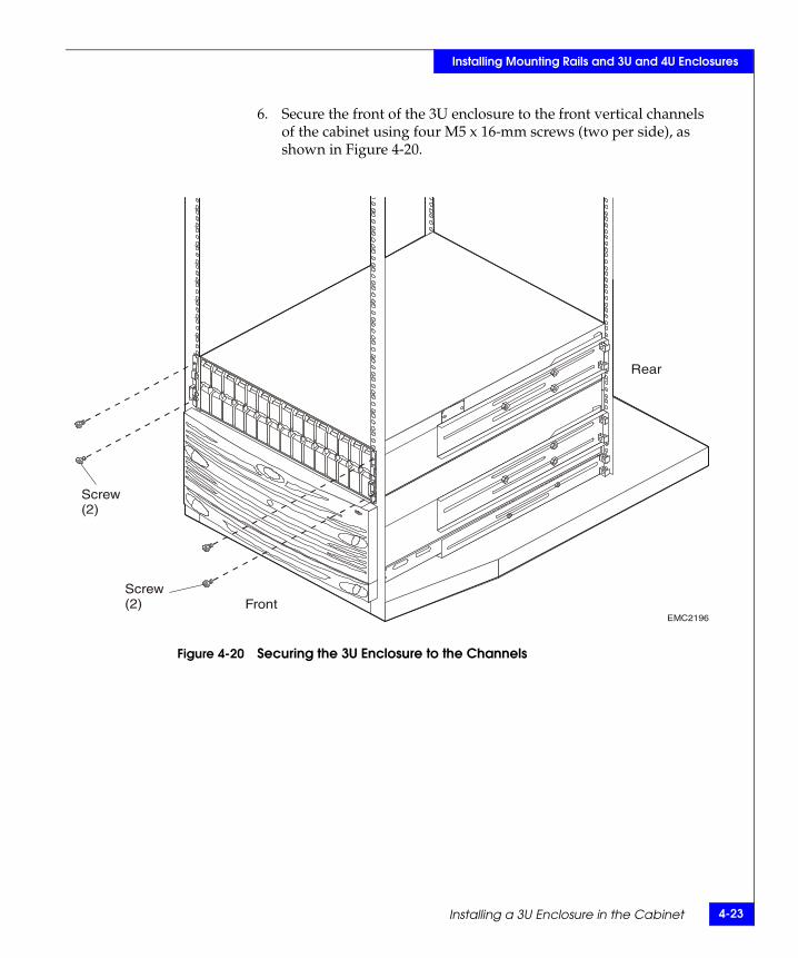
6. Secure the front of the 3U enclosure to the front vertical channels of the cabinet using four M5 x 16-mm screws (two per side), as shown in Figure 4-20.
Figure 4-20 Securing the 3U Enclosure to the Channels
EMC2196
Screw(2)
Screw(2)
Rear
Front

4-24 EMC Rails and Enclosures Installation Guide for 19-Inch NEMA Cabinets
Installing Mounting Rails and 3U and 4U Enclosures
7. Press the mounting tray bezel onto the latch brackets at the front of the cabinet until it snaps into place, then lock the bezel with the key. See Figure 4-21.
Figure 4-21 Attaching the 3U Front Bezel
8. If you are installing another device in the cabinet, skip steps 9 and 10, and continue with the appropriate instructions.
If you are not installing any more devices in the cabinet, replace the cabinet sides.
9. Cable the enclosure as described in the appropriate hardware reference or setup manual(s).
10. Refer to your device-specific hardware reference or setup guide for instructions on powering up the 3U device.
EMC2222
Installing Front Filler Panels 5-1
5
1U, 2U, and 3U filler panels are available to fill gaps in the NEMA rack. The latch bracket is designed to secure any size filler panel to the cabinet. The size of the filler panel determines the orientation of the latch bracket on the front channel.
This chapter discusses how to install the latch brackets and filler panels in empty spaces in the front of the cabinet. Major topics include
◆ Installing the 1U or 3U Latch Bracket .............................................5-2◆ Installing the 2U Latch Brackets ......................................................5-5◆ Installing the Filler Panel ..................................................................5-7
Installing Front FillerPanels
5-2 EMC Rails and Enclosures Installation Guide for 19-Inch NEMA Cabinets
Installing Front Filler Panels
Installing the 1U or 3U Latch BracketFollow these steps to install and orient the 1U or 3U filler panel latch brackets.
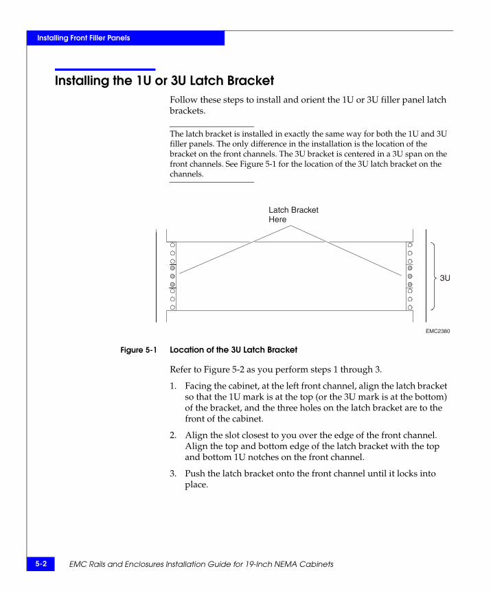
The latch bracket is installed in exactly the same way for both the 1U and 3U filler panels. The only difference in the installation is the location of the bracket on the front channels. The 3U bracket is centered in a 3U span on the front channels. See Figure 5-1 for the location of the 3U latch bracket on the channels.
Figure 5-1 Location of the 3U Latch Bracket
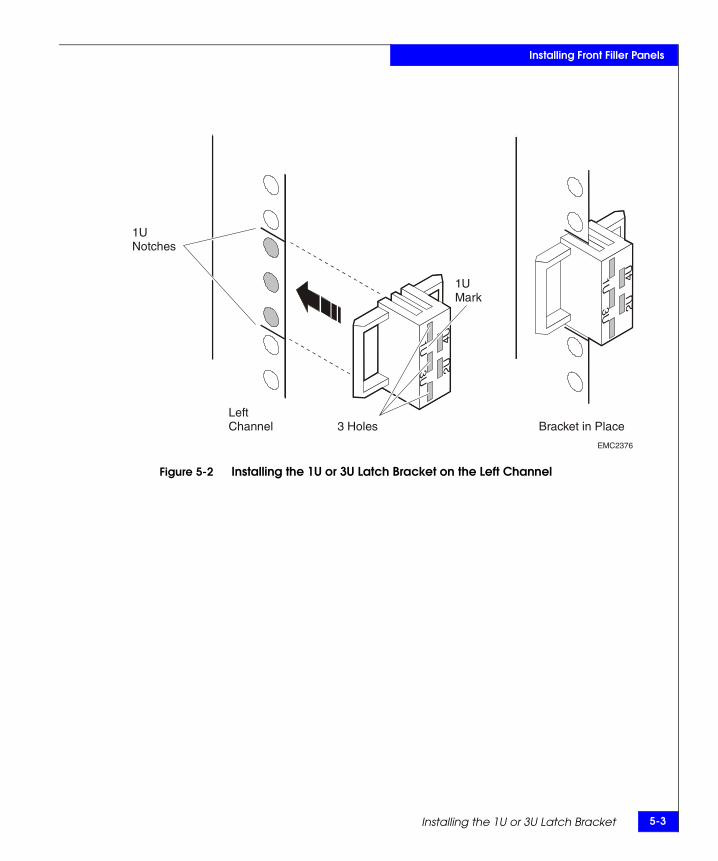
Refer to Figure 5-2 as you perform steps 1 through 3.
1. Facing the cabinet, at the left front channel, align the latch bracket so that the 1U mark is at the top (or the 3U mark is at the bottom) of the bracket, and the three holes on the latch bracket are to the front of the cabinet.
2. Align the slot closest to you over the edge of the front channel. Align the top and bottom edge of the latch bracket with the top and bottom 1U notches on the front channel.
3. Push the latch bracket onto the front channel until it locks into place.
EMC2380
3U
Latch BracketHere
Installing the 1U or 3U Latch Bracket 5-3
Installing Front Filler Panels
Figure 5-2 Installing the 1U or 3U Latch Bracket on the Left Channel
EMC2376
1UMark
3 Holes
1UNotches
LeftChannel Bracket in Place
5-4 EMC Rails and Enclosures Installation Guide for 19-Inch NEMA Cabinets
Installing Front Filler Panels
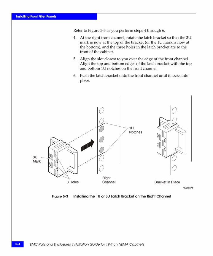
Refer to Figure 5-3 as you perform steps 4 through 6.
4. At the right front channel, rotate the latch bracket so that the 3U mark is now at the top of the bracket (or the 1U mark is now at the bottom), and the three holes in the latch bracket are to the front of the cabinet.
5. Align the slot closest to you over the edge of the front channel. Align the top and bottom edges of the latch bracket with the top and bottom 1U notches on the front channel.
6. Push the latch bracket onto the front channel until it locks into place.
Figure 5-3 Installing the 1U or 3U Latch Bracket on the Right Channel
EMC2377
3UMark
3 Holes
1UNotches
RightChannel Bracket in Place
Installing the 2U Latch Brackets 5-5
Installing Front Filler Panels
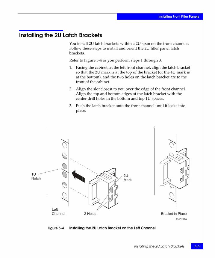
Installing the 2U Latch BracketsYou install 2U latch brackets within a 2U span on the front channels. Follow these steps to install and orient the 2U filler panel latch brackets.
Refer to Figure 5-4 as you perform steps 1 through 3.
1. Facing the cabinet, at the left front channel, align the latch bracket so that the 2U mark is at the top of the bracket (or the 4U mark is at the bottom), and the two holes on the latch bracket are to the front of the cabinet.
2. Align the slot closest to you over the edge of the front channel. Align the top and bottom edges of the latch bracket with the center drill holes in the bottom and top 1U spaces.
3. Push the latch bracket onto the front channel until it locks into place.
Figure 5-4 Installing the 2U Latch Bracket on the Left Channel
EMC2378
2UMark
2 Holes
1UNotch
LeftChannel Bracket in Place
5-6 EMC Rails and Enclosures Installation Guide for 19-Inch NEMA Cabinets
Installing Front Filler Panels
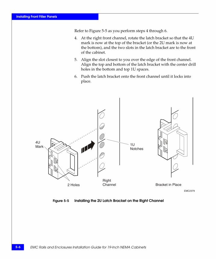
Refer to Figure 5-5 as you perform steps 4 through 6.
4. At the right front channel, rotate the latch bracket so that the 4U mark is now at the top of the bracket (or the 2U mark is now at the bottom), and the two slots in the latch bracket are to the front of the cabinet.
5. Align the slot closest to you over the edge of the front channel. Align the top and bottom of the latch bracket with the center drill holes in the bottom and top 1U spaces.
6. Push the latch bracket onto the front channel until it locks into place.
Figure 5-5 Installing the 2U Latch Bracket on the Right Channel
EMC2379
4UMark
2 Holes
1UNotches
RightChannel Bracket in Place
Installing the Filler Panel 5-7
Installing Front Filler Panels
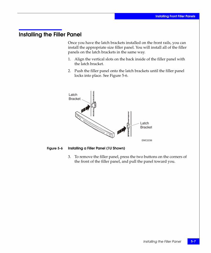
Installing the Filler PanelOnce you have the latch brackets installed on the front rails, you can install the appropriate size filler panel. You will install all of the filler panels on the latch brackets in the same way.
1. Align the vertical slots on the back inside of the filler panel with the latch bracket.
2. Push the filler panel onto the latch brackets until the filler panel locks into place. See Figure 5-6.
Figure 5-6 Installing a Filler Panel (1U Shown)
3. To remove the filler panel, press the two buttons on the corners of the front of the filler panel, and pull the panel toward you.
EMC2236
LatchBracket
LatchBracket
5-8 EMC Rails and Enclosures Installation Guide for 19-Inch NEMA Cabinets
Installing Front Filler Panels
Servicing a 40U Cabinet A-1
A
This appendix discusses how to handle and replace FRUs (Field Replaceable Units) in the standard EMC 40U cabinet.
Major topics include
◆ Handling FRUs..................................................................................A-2◆ Removing and Replacing a PDU Strip...........................................A-3◆ Removing and Replacing the Fan Module....................................A-6
Servicing a 40UCabinet
A-2 EMC Rails and Enclosures Installation Guide for 19-Inch NEMA Cabinets
Servicing a 40U Cabinet
Handling FRUsUse the precautions listed below when you remove, handle, or store FRUs.
◆ Do not remove a faulty FRU until you have a replacement available.
◆ Handle FRUs gently. A sudden jar or drop can permanently damage an FRU.
◆ Never use excessive force to remove or install an FRU.
◆ Store the FRU in the shipping container in which you received it. Use that container if you need to return the FRU for repair.
Removing and Replacing a PDU Strip A-3
Servicing a 40U Cabinet
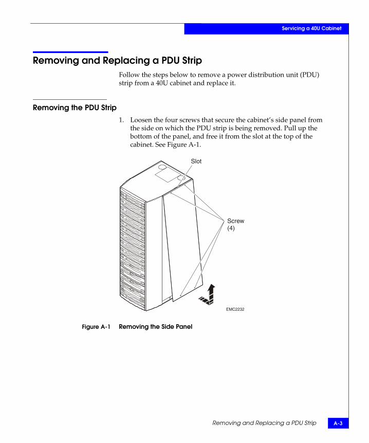
Removing and Replacing a PDU StripFollow the steps below to remove a power distribution unit (PDU) strip from a 40U cabinet and replace it.
Removing the PDU Strip
1. Loosen the four screws that secure the cabinet’s side panel from the side on which the PDU strip is being removed. Pull up the bottom of the panel, and free it from the slot at the top of the cabinet. See Figure A-1.
Figure A-1 Removing the Side Panel
EMC2232
Slot
Screw(4)
A-4 EMC Rails and Enclosures Installation Guide for 19-Inch NEMA Cabinets
Servicing a 40U Cabinet
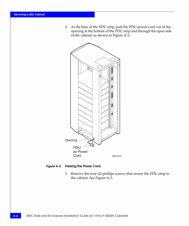
2. At the base of the PDU strip, pull the PDU power cord out of the opening at the bottom of the PDU strip and through the open side of the cabinet, as shown in Figure A-2.
Figure A-2 Freeing the Power Cord
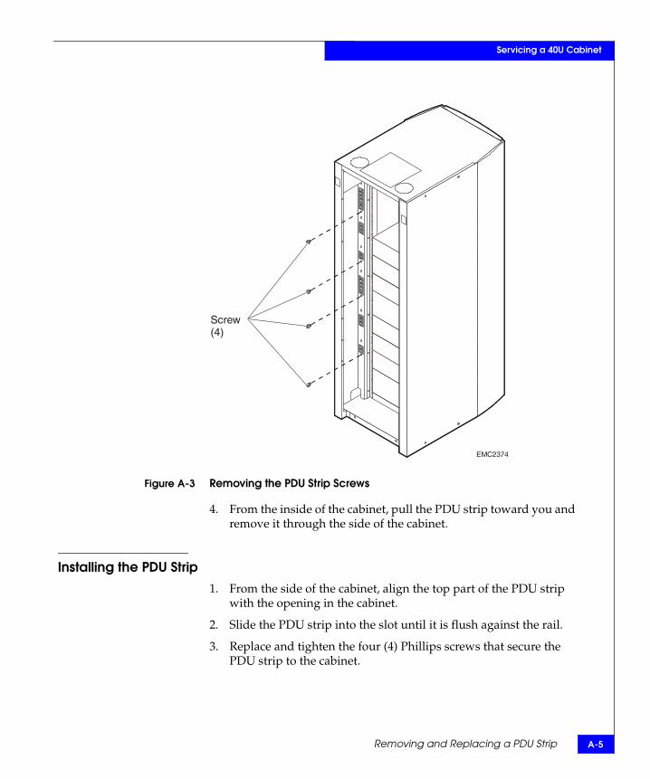
3. Remove the four (4) phillips screws that secure the PDU strip to the cabinet. See Figure A-3.
EMC2373
Opening
PDUac PowerCord
Removing and Replacing a PDU Strip A-5
Servicing a 40U Cabinet
Figure A-3 Removing the PDU Strip Screws
4. From the inside of the cabinet, pull the PDU strip toward you and remove it through the side of the cabinet.
Installing the PDU Strip1. From the side of the cabinet, align the top part of the PDU strip
with the opening in the cabinet.
2. Slide the PDU strip into the slot until it is flush against the rail.
3. Replace and tighten the four (4) Phillips screws that secure the PDU strip to the cabinet.
EMC2374
Screw(4)
A-6 EMC Rails and Enclosures Installation Guide for 19-Inch NEMA Cabinets
Servicing a 40U Cabinet
Removing and Replacing the Fan ModuleFollow the steps below to remove a fan module from a 40U cabinet and replace it.
Removing the Fan Module
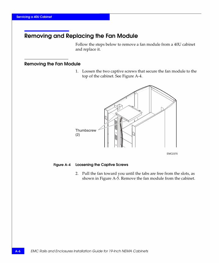
1. Loosen the two captive screws that secure the fan module to the top of the cabinet. See Figure A-4.
Figure A-4 Loosening the Captive Screws
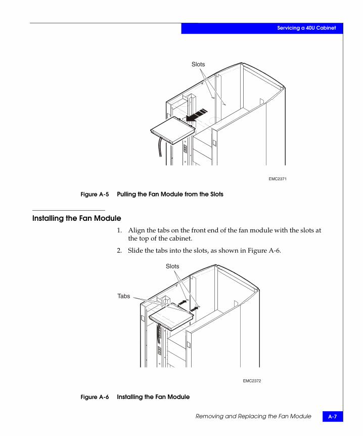
2. Pull the fan toward you until the tabs are free from the slots, as shown in Figure A-5. Remove the fan module from the cabinet.
EMC2370
Thumbscrew(2)
Removing and Replacing the Fan Module A-7
Servicing a 40U Cabinet
Figure A-5 Pulling the Fan Module from the Slots
Installing the Fan Module1. Align the tabs on the front end of the fan module with the slots at
the top of the cabinet.
2. Slide the tabs into the slots, as shown in Figure A-6.
Figure A-6 Installing the Fan Module
EMC2371
Slots
EMC2372
Tabs
Slots
A-8 EMC Rails and Enclosures Installation Guide for 19-Inch NEMA Cabinets
Servicing a 40U Cabinet
3. Tighten the captive screws to secure the fan module to the top of the cabinet.
40U Cabinet Technical Specifications B-1
BInvisible Body Tag
This appendix lists technical specifications of EMC’s standard 40U cabinet. Major sections are
◆ ac Power Specifications .................................................................... B-2◆ Sizes and Weights.............................................................................. B-3◆ Agency Standards ............................................................................. B-3
Most operational and environmental specifications are defined by the devices within the cabinet. Refer to your device-specific hardware reference documentation for detailed limits and restrictions.
40U Cabinet TechnicalSpecifications
B-2 EMC Rails and Enclosures Installation Guide for 19-Inch NEMA Cabinets
40U Cabinet Technical Specifications
ac Power SpecificationsThe 40U cabinet supplies 200-240 volts of single-phase ac power to devices connected to the redundant Power Distribution Units (PDUs). The PDUs are mounted within the cabinet on either side.
WARNING
You cannot connect 110-V devices to the 40U cabinet PDU power outlets.
The two PDUs contain circuit-breaker protection for the devices they power, and attach to external power mains with power cords that include plugs appropriate to your country.
Each PDU includes the following:
◆ 21 IEC-320, C13 power outlets (one reserved for upper fan tray)
• Outlets are divided into six individual branch circuits; six, three, two, five, three and two outlets per circuit (top down)
• Each branch is protected by a 15-A, 2-pole, inertial delay, push-to-reset circuit breaker
◆ One dual-pole 30-A magnetic circuit breaker that serves as
• a main power shutoff
• protection for PDU power outlets
◆ One pigtail cord with an L6-30P connector
Each cabinet can ship with two optional power inlet cords appropriate to the site. These approximately 15-foot power cords have one L6-30R receptacle and one of the following inlet plugs:
◆ L6-30P (North American and Japanese applications)
◆ IP-57 (Australia)
◆ IEC-309-332P6 (International applications not supported by L6-30P or IP-57)
◆ IEC-309-330P6 (some North American applications)
Sizes and Weights B-3
40U Cabinet Technical Specifications
Sizes and WeightsThe cabinet provides 70 inches of internal vertical space to mount a variety of electrical devices. Table B-1 lists the physical dimensions of the 40U cabinet.
Agency StandardsThe 40U cabinet is certified for use as Information Technology Equipment, and bears certification marks in accordance with the latest release of the following standards:
◆ UL 1950 (3rd Edition) - Information Technology Equipment.
◆ CSA 22.2 950-95 (3rd Edition) - Information Technology Equipment.
◆ EN60950 (2000) - Information Technology Equipment.
◆ CE Mark
Table B-1 40U Cabinet Physical Dimensions
Height (internal, usable for devices) 40U (70 inches) from floor pan to cabinet top (fan installed)
Height (overall) 75 inches
Width (usable for devices) NEMA 19-inch standard;rail holes 18.312 inches apart center-to-center
Width (overall) 24 inches
Depth (front to back rail) 24 or 28 inches, model-dependent
Depth (overall) 36 inches
Weight (empty) 300 pounds (135 kg)
Maximum total device weight supported 1400 pounds (630 kg)
B-4 EMC Rails and Enclosures Installation Guide for 19-Inch NEMA Cabinets
40U Cabinet Technical Specifications
EMC Rails and Enclosures Installation Guide for 19-Inch NEMA Cabinets i-1
Numerics1U, latch bracket, filler panel 5-22U, latch bracket, filler panel 5-53U
adjustable rails 4-8, 4-9bezel latch bracket 4-19enclosure, installing in the cabinet 4-18front bezel 4-24
3U, latch bracket, filler panel 5-24U
adjustable rails 4-5, 4-8, 4-9bezel latch bracket 4-13enclosure, installing in the cabinet 4-12front bezel 4-17
Aac power B-2adjustable rails 2-5
3U and 4U 4-5, 4-8, 4-9Control Station 3-5
agency standards B-3
Bbezel, front
3U 4-244U 4-17Control Station 3-12SPS 2-16
Ccabinet
device position 1-2removing sides 3-3, 4-3third party 4-1, 4-2
channel, round-hole 3-9channel, square-hole 2-11, 3-5, 3-10chassis, see enclosure 4-2circuit breakers B-2clip 2-7connectors, power B-2Control Station
front bezel 3-12installing 3-11see also Chapter 3 3-1
cooling fans, internal 1-2cooling requirements 1-2
DData Mover Enclosure (DME) 1-4device
height requirements 1-5placement requirements 1-2position in the cabinet 1-2
disk-array enclosure (DAE2) 1-5, 2-16, 4-3, 4-11disk-processor enclosure (DPE2) 1-5, 2-16, 4-3,
4-11
Eenclosure, installing in the cabinet 4-2
Index
EMC Rails and Enclosures Installation Guide for 19-Inch NEMA Cabinetsi-2
Index
Ffan module 1-2
installing A-7internal cooling 1-2removing A-6replacing A-6
filler panel1U latch bracket 5-22U latch bracket 5-53U latch bracket 5-2installing 5-7
FRUsfaulty A-2handling A-2removing A-3replacing A-3
Hhandling FRUs A-2height requirements, devices 1-5
Llatch bracket
filler panel1U 5-22U 5-53U 5-2
front bezel3U 4-194U 4-13
lip 2-9
Mmounting rails, installing in cabinet 3-5, 4-5
NNEMA, unit heights 1-5
PPDU strip
removing and replacing A-3placement, devices 1-2
powercords B-2distribution 1-4specifications B-2
Rrails
3U and 4U enclosure 4-5adjustable 2-5Control Station 3-5SPS 2-5
round-hole channel 3-9
Ssite requirements 1-1, 5-1size B-3specifications B-1
agency standards B-3power B-2size and weight B-3
SPSfront bezel, installing 2-16installing in the cabinet 2-2, 3-2installing on the tray 2-12
square-hole channel 2-11, 3-5, 3-10standards, agency B-3Storage Processor Enclosure (SPE) 1-3, 1-5, 4-11
Tthird party cabinet 4-1, 4-2tray, SPS 2-8
UU, NEMA units 1-5unit heights, NEMA 1-5
Wweight B-3write caching 2-8