Embed Size (px)
Citation preview
Embedded Systems in SiliconTD5102
Advanced Architectureswith emphasis on ILP exploitation
Henk Corporaalhttp://www.ics.ele.tue.nl/~heco/courses/EmbSystems
Technical University Eindhoven
DTI / NUS Singapore
2005/2006
H.C. TD5102 2
Future
We foresee that
many characteristics of current high performance architectures will find their way into the embedded domain.

H.C. TD5102 3
What are we talking about?
ILP = Instruction Level Parallelism =
ability to perform multiple operations (or instructions),from a single instruction stream,
in parallel

H.C. TD5102 4
Processor Components
Overview
• Motivation and Goals
• Trends in Computer Architecture
• ILP Processors
• Transport Triggered Architectures
• Configurable components
• Summary and Conclusions
H.C. TD5102 5
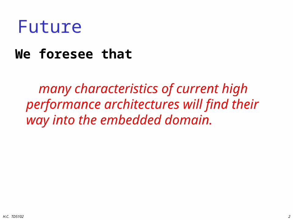
Motivation for ILP (and other types of parallelism)• Increasing VLSI densities; decreasing feature size
• Increasing performance requirements
• New application areas, like– Multi-media (image, audio, video, 3-D)– intelligent search and filtering engines– neural, fuzzy, genetic computing
• More functionality
• Use of existing Code (Compatibility)
• Low Power: P = fCV2
H.C. TD5102 6
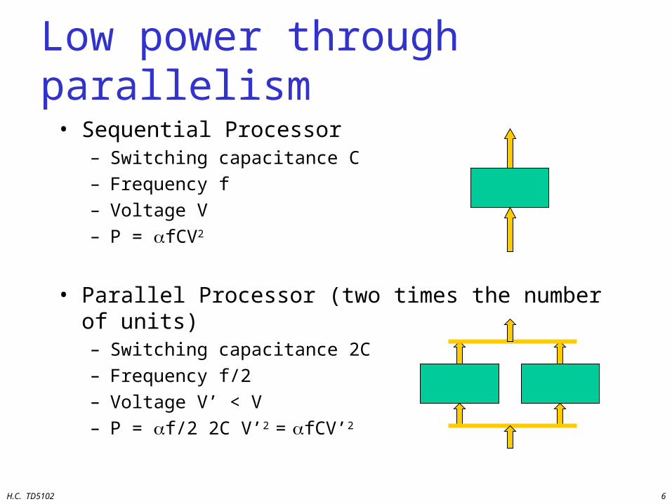
Low power through parallelism
• Sequential Processor– Switching capacitance C– Frequency f– Voltage V– P = fCV2
• Parallel Processor (two times the number of units)– Switching capacitance 2C– Frequency f/2– Voltage V’ < V– P = f/2 2C V’2 = fCV’2
H.C. TD5102 7
ILP Goals
• Making the most powerful single chip processor
• Exploiting parallelism between independent instructions (or operations) in programs
• Exploit hardware concurrency– multiple FUs, buses, reg files, bypass paths, etc.
• Code compatibility– binary: superscalar and super-pipelined– HLL: VLIW
• Incorporate enhanced functionality (ASIP)
H.C. TD5102 8
Overview
• Motivation and Goals
• Trends in Computer Architecture
• ILP Processors
• Transport Triggered Architectures
• Configurable components
• Summary and Conclusions

H.C. TD5102 9
Trends in Computer Architecture
• Bridging the semantic gap• Performance increase• VLSI developments• Architecture developments: design space• The role of compiler• Right match
H.C. TD5102 10
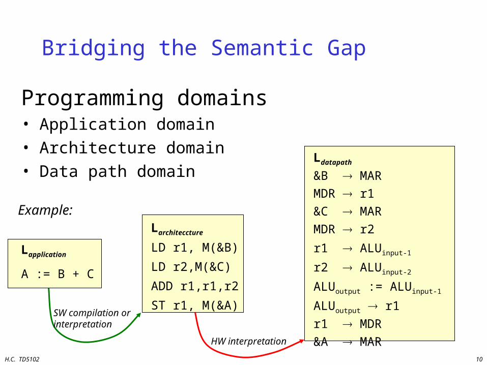
Bridging the Semantic Gap
Programming domains• Application domain• Architecture domain• Data path domain
Larchiteccture
LD r1, M(&B)
LD r2,M(&C)
ADD r1,r1,r2
ST r1, M(&A)SW compilation orinterpretation
Ldatapath
&B MARMDR r1&C MARMDR r2
r1 ALUinput-1
r2 ALUinput-2
ALUoutput := ALUinput-1
ALUoutput r1r1 MDR&A MARHW interpretation
Lapplication
A := B + C
Example:
H.C. TD5102 11
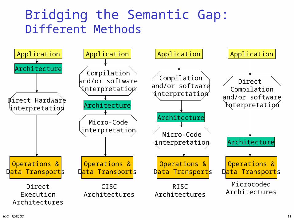
Bridging the Semantic Gap: Different Methods
Direct Hardwareinterpretation
Direct Execution Architectures
Application
Architecture
Operations &Data Transports
Application
Compilationand/or softwareinterpretation
Architecture
Micro-Codeinterpretation
Operations &Data Transports
CISC Architectures
Application
Compilationand/or softwareinterpretation
Architecture
Micro-Codeinterpretation
Operations &Data Transports
RISC Architectures
Application
Direct Compilation
and/or softwareinterpretation
Architecture
Operations &Data Transports
Microcoded Architectures
H.C. TD5102 12
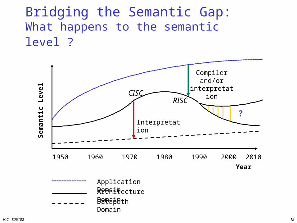
Bridging the Semantic Gap: What happens to the semantic level ?
Interpretation
Compiler and/or
interpretation
?
Year
Sem
anti
c L
evel
1950 1960 1970 1980 1990 2000
Application Domain
Architecture Domain
Datapath Domain
CISCRISC
2010
H.C. TD5102 13
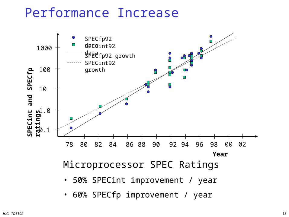
Performance Increase
Year
78 80 82 84 86 88 90 92 94 96 98
0.1
1.0
10
100
1000
SPECfp92 dataSPECint92 data
SPECfp92 growthSPECint92 growth
SP
EC
int
and
SP
EC
fp r
atin
gs
Microprocessor SPEC Ratings
• 50% SPECint improvement / year
• 60% SPECfp improvement / year
00 02
H.C. TD5102 14
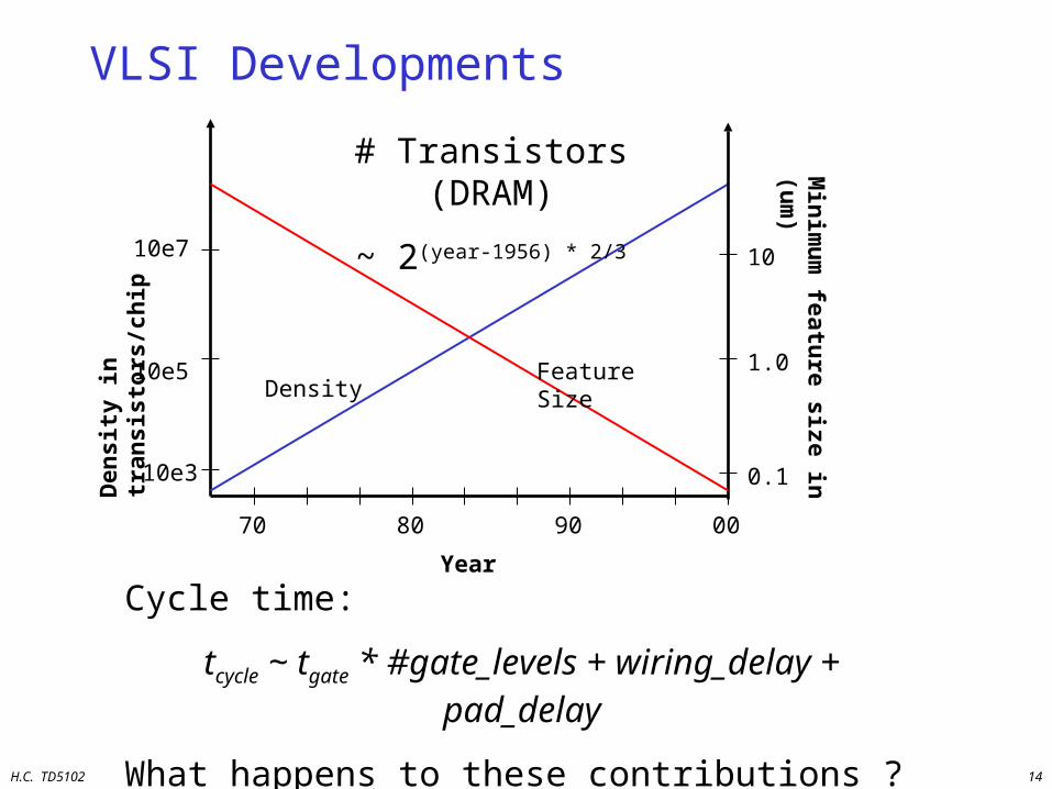
VLSI Developments
Year
70 80 90 00
10e3
10e5
10e7
Den
sity
in t
ran
sist
ors
/ch
ip
0.1
1.0
10M
inim
um
feature size in
(um
)
DensityFeature Size
# Transistors (DRAM)
~ 2(year-1956) * 2/3
Cycle time:
tcycle ~ tgate * #gate_levels + wiring_delay + pad_delay
What happens to these contributions ?
H.C. TD5102 15
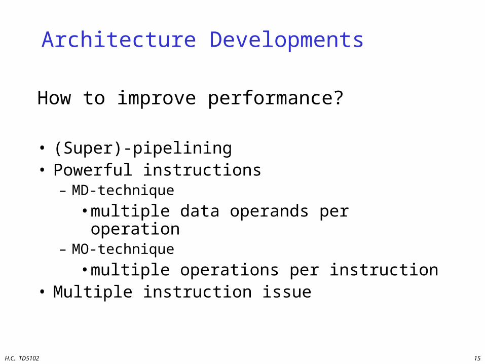
Architecture Developments
How to improve performance?
• (Super)-pipelining• Powerful instructions
– MD-technique
• multiple data operands per operation– MO-technique
• multiple operations per instruction• Multiple instruction issue
H.C. TD5102 16
Architecture Developments
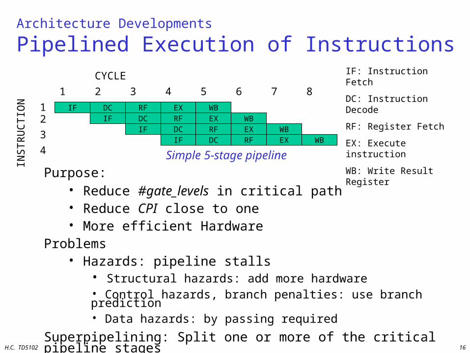
Pipelined Execution of InstructionsIF: Instruction Fetch
DC: Instruction Decode
RF: Register Fetch
EX: Execute instruction
WB: Write Result Register
IF DC RF EX WBIF DC RF EX WB
IF DC RF EX WBIF DC RF EX WB
INS
TR
UC
TIO
N
CYCLE
1 2 43 5 6 7 8
12
3
4
Purpose:• Reduce #gate_levels in critical path• Reduce CPI close to one• More efficient Hardware
Problems• Hazards: pipeline stalls
• Structural hazards: add more hardware• Control hazards, branch penalties: use branch prediction• Data hazards: by passing required
Superpipelining: Split one or more of the critical pipeline stages
Simple 5-stage pipeline
H.C. TD5102 17
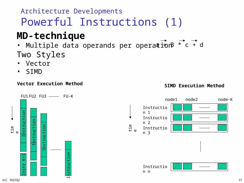
Architecture Developments
Powerful Instructions (1)MD-technique• Multiple data operands per operation
Two Styles• Vector• SIMD
SIMD Execution Method
time
Instruction 1
Instruction 2
Instruction 3
Instruction n
node1 node2 node-K
Inst
r K
+1
Inst
ruct
ion
1
Inst
ruct
ion
2
Inst
ruct
ion
3
Inst
ruct
ion
K
time
FU1FU2 FU3 FU-K
Vector Execution Method
a = B * c + d
H.C. TD5102 18
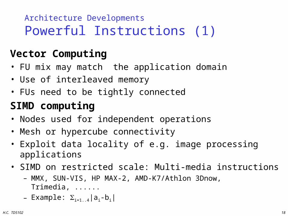
Architecture Developments
Powerful Instructions (1)
Vector Computing• FU mix may match the application domain• Use of interleaved memory• FUs need to be tightly connected
SIMD computing• Nodes used for independent operations• Mesh or hypercube connectivity• Exploit data locality of e.g. image processing applications• SIMD on restricted scale: Multi-media instructions
– MMX, SUN-VIS, HP MAX-2, AMD-K7/Athlon 3Dnow, Trimedia, ......
– Example: i=1..4|ai-bi|
H.C. TD5102 19
Architecture Developments
Powerful Instructions (2)
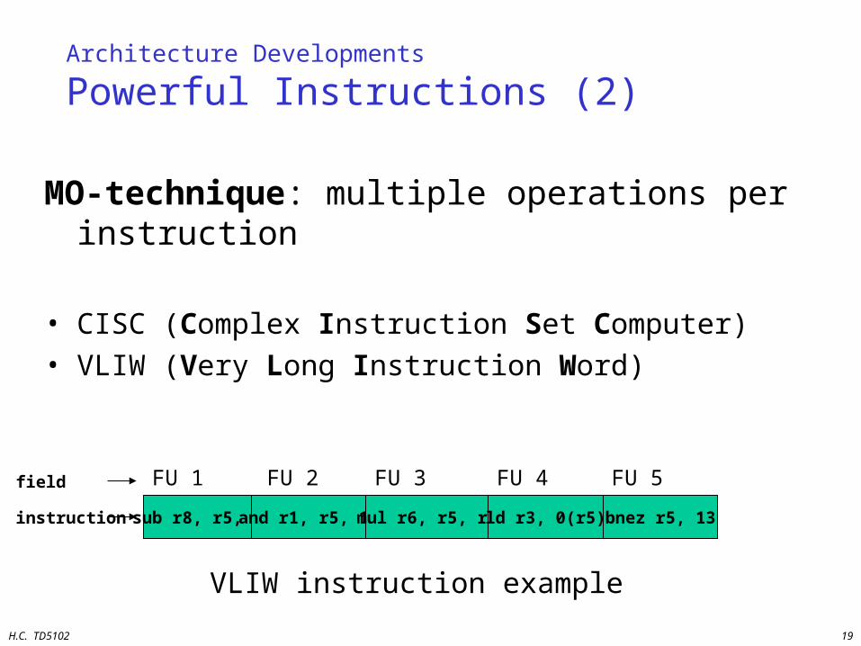
MO-technique: multiple operations per instruction
• CISC (Complex Instruction Set Computer)• VLIW (Very Long Instruction Word)
sub r8, r5, 3 and r1, r5, 12 mul r6, r5, r2 ld r3, 0(r5)
FU 1 FU 2 FU 3 FU 4field
instruction bnez r5, 13
FU 5
VLIW instruction example
H.C. TD5102 20
Architecture Developments: Powerful Instructions (2)
VLIW Characteristics
• Only RISC like operation support Short cycle times
• Flexible: Can implement any FU mixture• Extensible• Tight inter FU connectivity required• Large instructions• Not binary compatible
H.C. TD5102 21
Architecture Developments
Multiple instruction issue (per cycle)
Who guarantees semantic correctness?
• User specifies multiple instruction streams– MIMD (Multiple Instruction Multiple Data)
• Run-time detection of ready instructions– Superscalar
• Compile into dataflow representation– Dataflow processors
H.C. TD5102 22
Multiple instruction issue
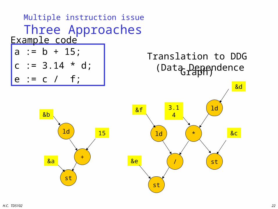
Three Approaches
a := b + 15;
c := 3.14 * d;
e := c / f;
Translation to DDG (Data Dependence Graph)
ld
+
st
&b
15
&a
ld *
/ st
ld
st
&f 3.14
&e
&d
&c
Example code
H.C. TD5102 23
Generated Code
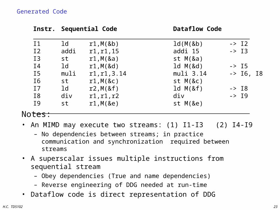
Instr. Sequential Code Dataflow Code I1 ld r1,M(&b) ld(M(&b) -> I2I2 addi r1,r1,15 addi 15 -> I3I3 st r1,M(&a) st M(&a)I4 ld r1,M(&d) ld M(&d) -> I5I5 muli r1,r1,3.14 muli 3.14 -> I6, I8I6 st r1,M(&c) st M(&c)I7 ld r2,M(&f) ld M(&f) -> I8I8 div r1,r1,r2 div -> I9I9 st r1,M(&e) st M(&e) Notes:
• An MIMD may execute two streams: (1) I1-I3 (2) I4-I9– No dependencies between streams; in practice communication and
synchronization required between streams
• A superscalar issues multiple instructions from sequential stream– Obey dependencies (True and name dependencies)
– Reverse engineering of DDG needed at run-time
• Dataflow code is direct representation of DDG

H.C. TD5102 24
Instruction Pipeline Overview
IF DC RF EX WB
IF DC/RF EX WB
CISC
RISC
IF1 DC1 RF1 EX1 ROBISSUE WB1
IF2 DC2 RF2 EX2 ROBISSUE WB2
IF3 DC3 RF3 EX3 ROBISSUE WB3
IFk DCk RFk EXk ROBISSUE WBk
Superscalar
IF1 IF2 IFs DC RF--- EX1 EX2 --- EX5 WBSuperpipelined
IF DC
RF1 EX1 WB1
RF2 EX2 WB2
RFk EXk WBk
VLIW
RF1 EX1 WB1
RF2 EX2 WB2
RFk EXk WBkD
AT
AF
LOW
H.C. TD5102 25
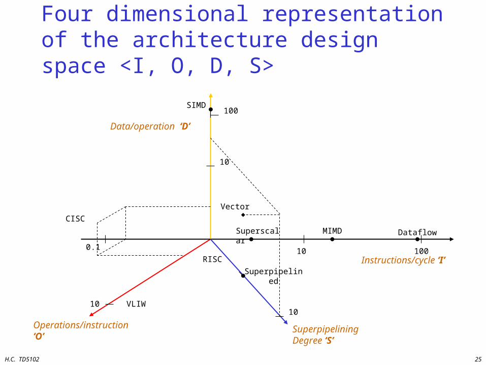
Four dimensional representation of the architecture design space <I, O, D, S>
Instructions/cycle ‘I’
Superpipelining Degree ‘S’
Operations/instruction ‘O’
Data/operation ‘D’
Superscalar MIMD Dataflow
Superpipelined
RISC
VLIW
10 100
1010
0.1
Vector
10
SIMD100
CISC
H.C. TD5102 26
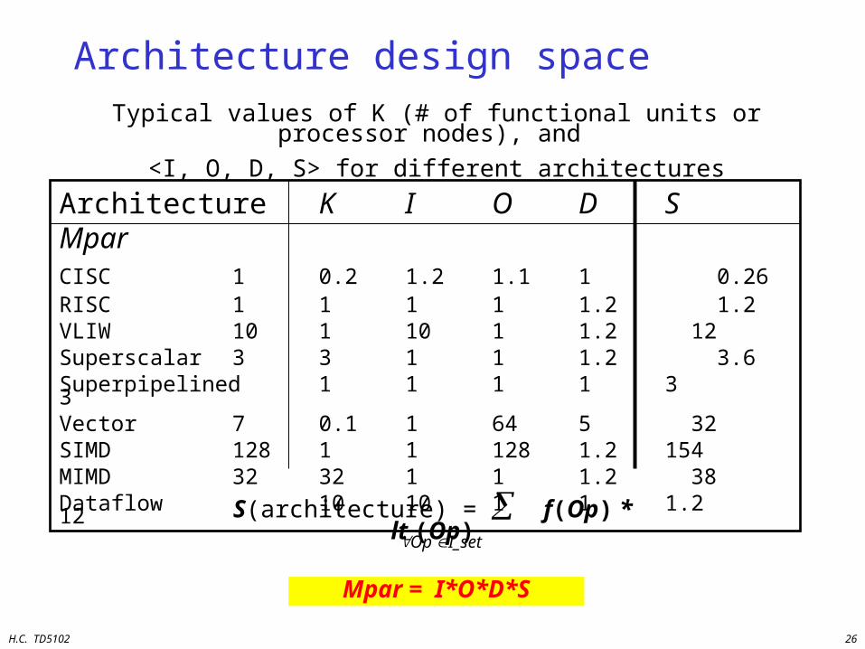
Architecture design space
Architecture K I O D S MparCISC 1 0.2 1.2 1.1 1 0.26RISC 1 1 1 1 1.2 1.2VLIW 10 1 10 1 1.2 12Superscalar 3 3 1 1 1.2 3.6Superpipelined 1 1 1 1 3 3Vector 7 0.1 1 64 5 32SIMD 128 1 1 128 1.2 154MIMD 32 32 1 1 1.2 38Dataflow 10 10 1 1 1.2 12
Typical values of K (# of functional units or processor nodes), and
<I, O, D, S> for different architectures
Mpar = I*O*D*S
Op I_set
S(architecture) = f(Op) * lt (Op)
H.C. TD5102 27
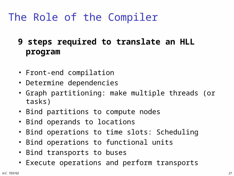
The Role of the Compiler
9 steps required to translate an HLL program
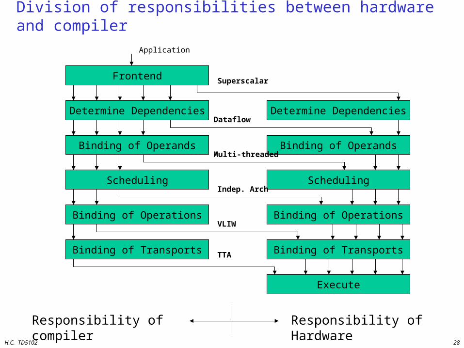
• Front-end compilation• Determine dependencies• Graph partitioning: make multiple threads (or tasks)• Bind partitions to compute nodes• Bind operands to locations• Bind operations to time slots: Scheduling• Bind operations to functional units• Bind transports to buses• Execute operations and perform transports
H.C. TD5102 28
Division of responsibilities between hardware and compiler
Frontend
Binding of Operands
Determine Dependencies
Scheduling
Binding of Transports
Binding of Operations
Execute
Binding of Operands
Determine Dependencies
Scheduling
Binding of Transports
Binding of Operations
Responsibility of compiler Responsibility of Hardware
Application
Superscalar
Dataflow
Multi-threaded
Indep. Arch
VLIW
TTA
H.C. TD5102 29
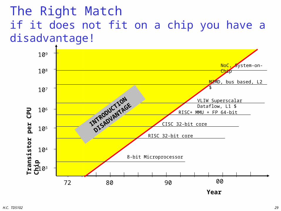
The Right Matchif it does not fit on a chip you have a disadvantage!
Year
72 80 90
103
104
105
106
107
Tra
nsi
sto
r p
er C
PU
Ch
ip
00
108
8-bit Microprocessor
RISC 32-bit core
CISC 32-bit core
RISC+ MMU + FP 64-bit
VLIW Superscalar Dataflow, L1 $
MIMD, bus based, L2 $
INTRODUCTIO
N
DISADVANTAGE
109
NoC, System-on-Chip
H.C. TD5102 30
Overview
• Motivation and Goals
• Trends in Computer Architecture
• ILP Processors
• Transport Triggered Architectures
• Configurable components
• Summary and Conclusions

H.C. TD5102 31
ILP Processors• Overview• General ILP organization• VLIW concept
– examples like: TriMedia, Mpact, TMS320C6x, IA-64
• Superscalar concept– examples like: HP-PA8000, Alpha 21264, MIPS
R10k/R12k, Pentium I-IV, AMD5-7, UltraSparc – (Ref: IEEE Micro April 1996 (HotChips issue)
• Comparing Superscalar and VLIW

H.C. TD5102 32
General ILP processor organization
Instruction FetchUnit
Inst
ruct
ion
M
em
ory Instruction
DecodeUnit
FU-1
FU-2
FU-K
Re
gis
ter
File
Da
taM
em
ory
Central Processing Unit

H.C. TD5102 33
ILP processor characteristics
• Issue multiple operations/instructions per cycle
• Multiple concurrent Function Units
• Pipelined execution
• Shared register file
• Four Superscalar variants– In-order/Out-of-order execution– In-order/Out-of-order completion
H.C. TD5102 34
VLIW
Very Long Instruction WordArchitecture
H.C. TD5102 35
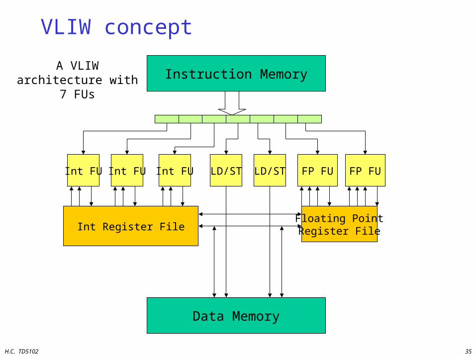
VLIW concept
Int Register File
Instruction Memory
Int FU
A VLIW architecture with 7 FUs
Data Memory
Int FU Int FU LD/ST LD/ST FP FU
Floating PointRegister File
FP FU
H.C. TD5102 36
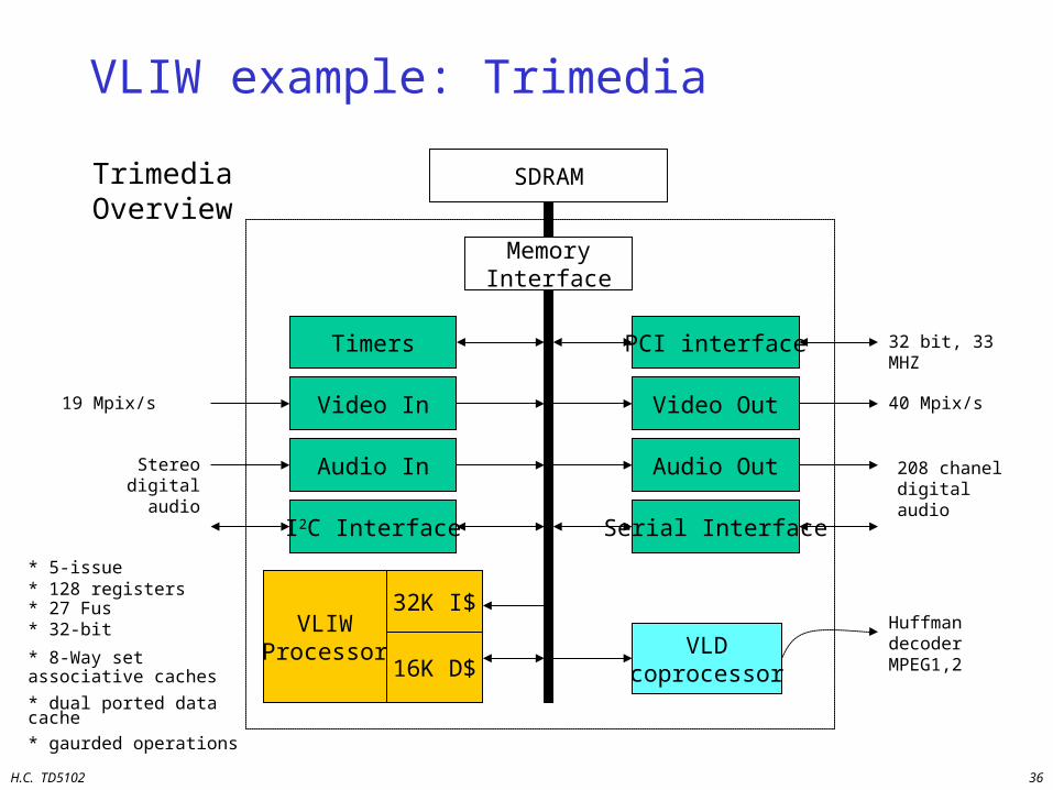
VLIW example: Trimedia
SDRAM
Timers
MemoryInterface
PCI interface
Video In Video Out
Audio In Audio Out
I2C Interface Serial Interface
VLIWProcessor
32K I$
16K D$VLD
coprocessor
32 bit, 33 MHZ
40 Mpix/s
208 chanel digital audio
Huffman decoder MPEG1,2
19 Mpix/s
Stereo digital audio
* 5-issue* 128 registers* 27 Fus* 32-bit
* 8-Way set associative caches
* dual ported data cache
* gaurded operations
Trimedia Overview
H.C. TD5102 37
VLIW example: TMS320C62
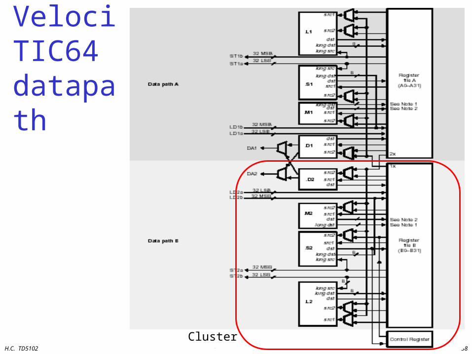
TMS320C62 VelociTI Processor
• 8 operations (of 32-bit) per instruction (256 bit)• Two clusters
– 8 Fus: 4 Fus / cluster : (2 Multipliers, 6 ALUs)– 2 x 16 registers– One port available to read from register file of other cluster
• Flexible addressing modes (like circular addressing)• Flexible instruction packing• All operations conditional• 5 ns, 200 MHz, 0.25 um, 5-layer CMOS• 128 KB on-chip RAM
H.C. TD5102 38
VelociTIC64 datapath
Cluster
H.C. TD5102 39
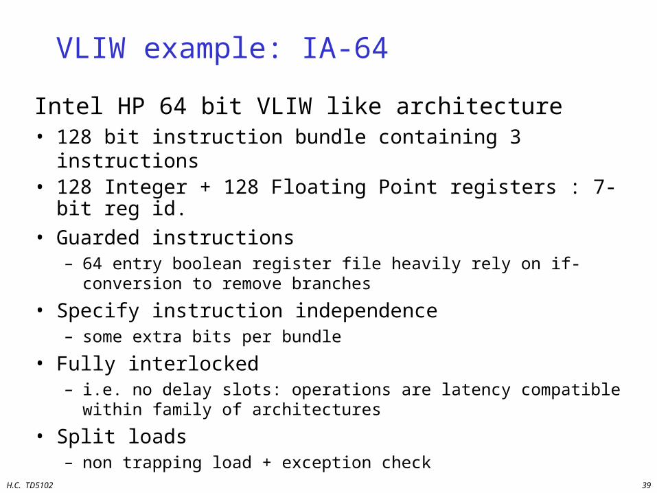
VLIW example: IA-64
Intel HP 64 bit VLIW like architecture• 128 bit instruction bundle containing 3 instructions• 128 Integer + 128 Floating Point registers : 7-bit reg id.
• Guarded instructions– 64 entry boolean register file heavily rely on if-conversion to
remove branches
• Specify instruction independence– some extra bits per bundle
• Fully interlocked– i.e. no delay slots: operations are latency compatible within family
of architectures
• Split loads– non trapping load + exception check

H.C. TD5102 40
Intel Itanium 2• EPIC• 0.18um 6ML• 8 issue slots• 1 GHz
(8000 MIPS)• 130 W (max)• 61 MOPS/W• 128b bundle
(3x41b + 5b)
H.C. TD5102 41
Superscalar
Multiple Instructions / Cycle

H.C. TD5102 42
Superscalar: Concept
InstructionMemory
InstructionCache
Decoder
BranchUnit
ALU-1 ALU-2Logic &
ShiftLoadUnit
StoreUnit
ReorderBuffer
RegisterFile
DataCache
DataMemory
Reservation Stations
Address
DataData
Instruction
H.C. TD5102 43
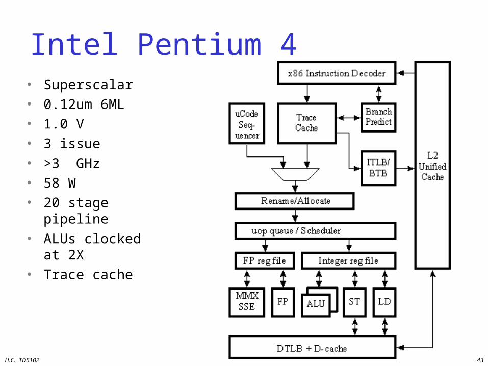
Intel Pentium 4• Superscalar• 0.12um 6ML• 1.0 V• 3 issue• >3 GHz• 58 W• 20 stage pipeline• ALUs clocked at
2X• Trace cache
H.C. TD5102 44
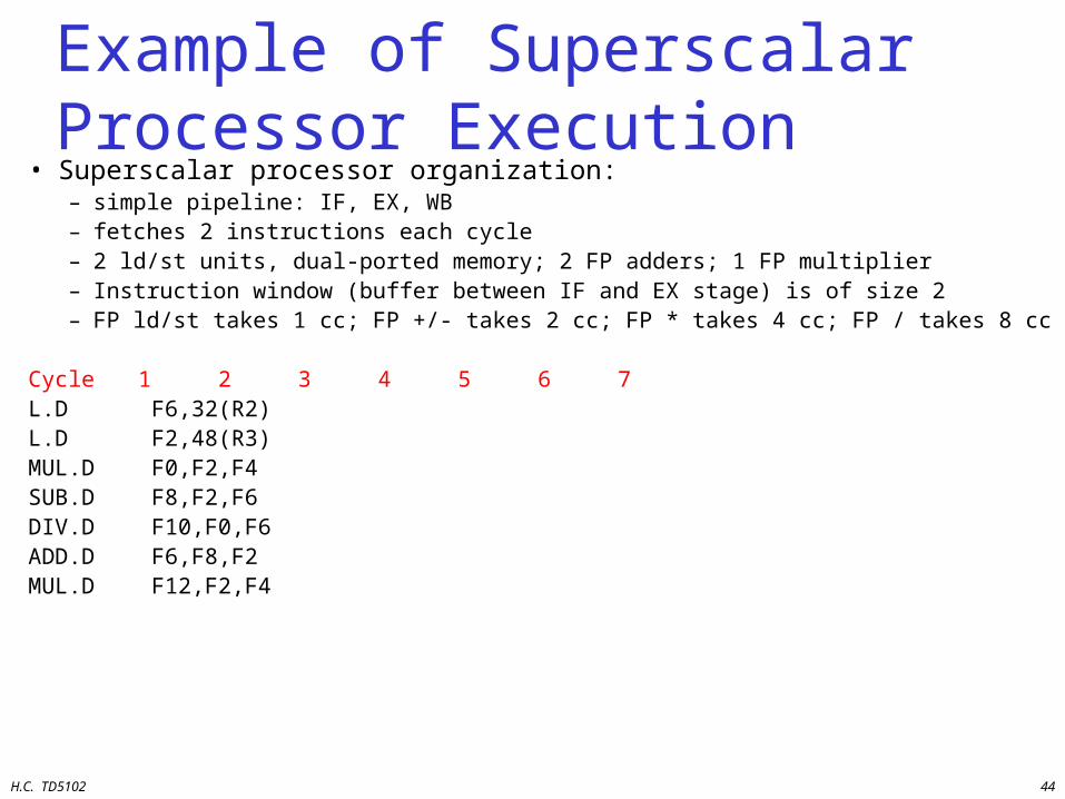
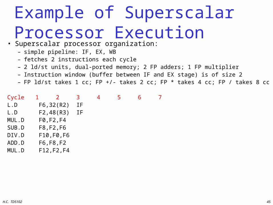
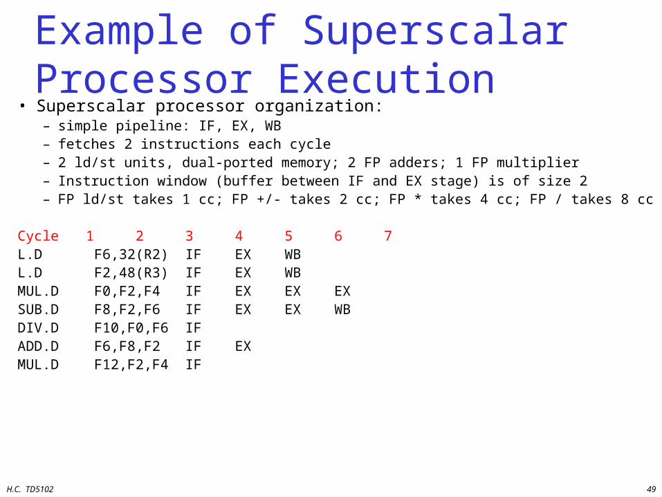
Example of Superscalar Processor Execution
• Superscalar processor organization:– simple pipeline: IF, EX, WB– fetches 2 instructions each cycle– 2 ld/st units, dual-ported memory; 2 FP adders; 1 FP multiplier– Instruction window (buffer between IF and EX stage) is of size 2– FP ld/st takes 1 cc; FP +/- takes 2 cc; FP * takes 4 cc; FP / takes 8 cc
Cycle 1 2 3 4 5 6 7L.D F6,32(R2)L.D F2,48(R3)MUL.D F0,F2,F4SUB.D F8,F2,F6DIV.D F10,F0,F6ADD.D F6,F8,F2MUL.D F12,F2,F4
H.C. TD5102 45
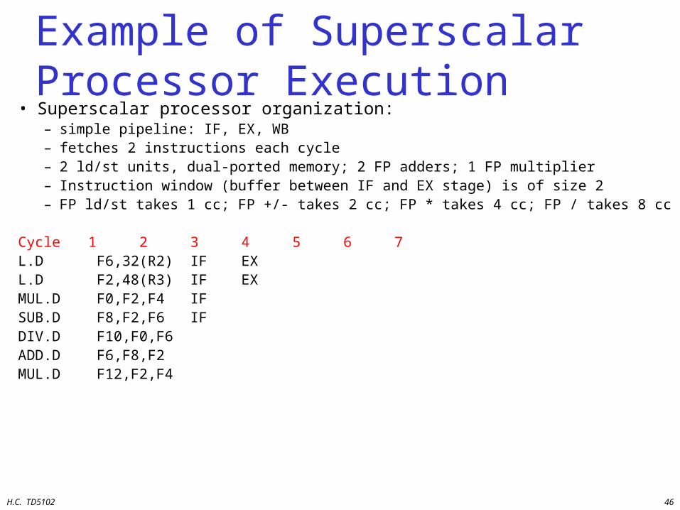
Example of Superscalar Processor Execution
• Superscalar processor organization:– simple pipeline: IF, EX, WB– fetches 2 instructions each cycle– 2 ld/st units, dual-ported memory; 2 FP adders; 1 FP multiplier– Instruction window (buffer between IF and EX stage) is of size 2– FP ld/st takes 1 cc; FP +/- takes 2 cc; FP * takes 4 cc; FP / takes 8 cc
Cycle 1 2 3 4 5 6 7L.D F6,32(R2) IFL.D F2,48(R3) IFMUL.D F0,F2,F4SUB.D F8,F2,F6DIV.D F10,F0,F6ADD.D F6,F8,F2MUL.D F12,F2,F4
H.C. TD5102 46
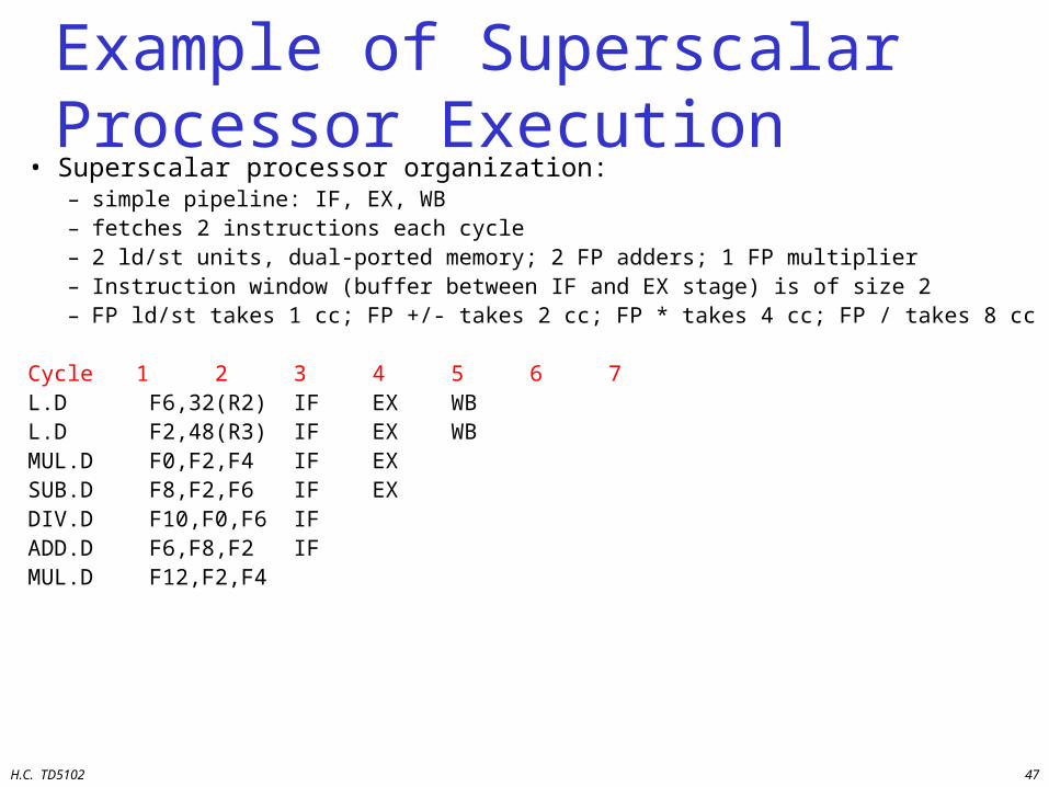
Example of Superscalar Processor Execution
• Superscalar processor organization:– simple pipeline: IF, EX, WB– fetches 2 instructions each cycle– 2 ld/st units, dual-ported memory; 2 FP adders; 1 FP multiplier– Instruction window (buffer between IF and EX stage) is of size 2– FP ld/st takes 1 cc; FP +/- takes 2 cc; FP * takes 4 cc; FP / takes 8 cc
Cycle 1 2 3 4 5 6 7L.D F6,32(R2) IF EXL.D F2,48(R3) IF EXMUL.D F0,F2,F4 IFSUB.D F8,F2,F6 IFDIV.D F10,F0,F6ADD.D F6,F8,F2MUL.D F12,F2,F4
H.C. TD5102 47
Example of Superscalar Processor Execution
• Superscalar processor organization:– simple pipeline: IF, EX, WB– fetches 2 instructions each cycle– 2 ld/st units, dual-ported memory; 2 FP adders; 1 FP multiplier– Instruction window (buffer between IF and EX stage) is of size 2– FP ld/st takes 1 cc; FP +/- takes 2 cc; FP * takes 4 cc; FP / takes 8 cc
Cycle 1 2 3 4 5 6 7L.D F6,32(R2) IF EX WBL.D F2,48(R3) IF EX WBMUL.D F0,F2,F4 IF EXSUB.D F8,F2,F6 IF EXDIV.D F10,F0,F6 IFADD.D F6,F8,F2 IFMUL.D F12,F2,F4
H.C. TD5102 48
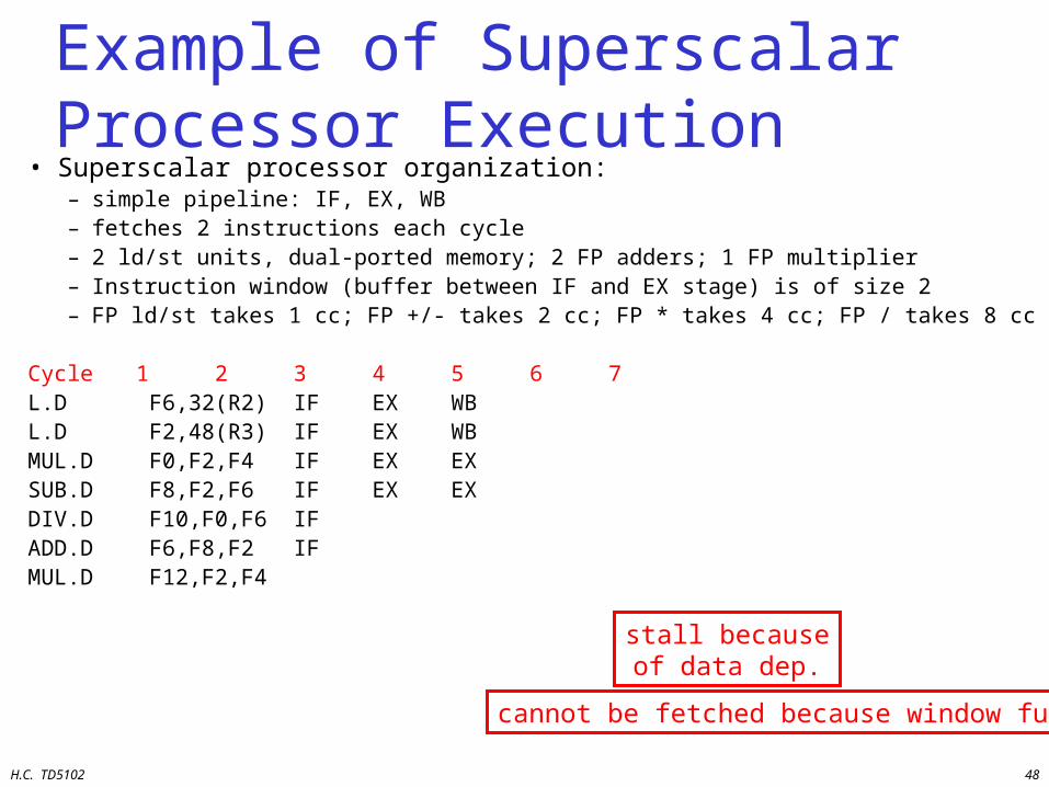
Example of Superscalar Processor Execution
• Superscalar processor organization:– simple pipeline: IF, EX, WB– fetches 2 instructions each cycle– 2 ld/st units, dual-ported memory; 2 FP adders; 1 FP multiplier– Instruction window (buffer between IF and EX stage) is of size 2– FP ld/st takes 1 cc; FP +/- takes 2 cc; FP * takes 4 cc; FP / takes 8 cc
Cycle 1 2 3 4 5 6 7L.D F6,32(R2) IF EX WBL.D F2,48(R3) IF EX WBMUL.D F0,F2,F4 IF EX EXSUB.D F8,F2,F6 IF EX EXDIV.D F10,F0,F6 IFADD.D F6,F8,F2 IFMUL.D F12,F2,F4
stall becauseof data dep.
cannot be fetched because window full
H.C. TD5102 49
Example of Superscalar Processor Execution
• Superscalar processor organization:– simple pipeline: IF, EX, WB– fetches 2 instructions each cycle– 2 ld/st units, dual-ported memory; 2 FP adders; 1 FP multiplier– Instruction window (buffer between IF and EX stage) is of size 2– FP ld/st takes 1 cc; FP +/- takes 2 cc; FP * takes 4 cc; FP / takes 8 cc
Cycle 1 2 3 4 5 6 7L.D F6,32(R2) IF EX WBL.D F2,48(R3) IF EX WBMUL.D F0,F2,F4 IF EX EX EXSUB.D F8,F2,F6 IF EX EX WBDIV.D F10,F0,F6 IFADD.D F6,F8,F2 IF EXMUL.D F12,F2,F4 IF

H.C. TD5102 50
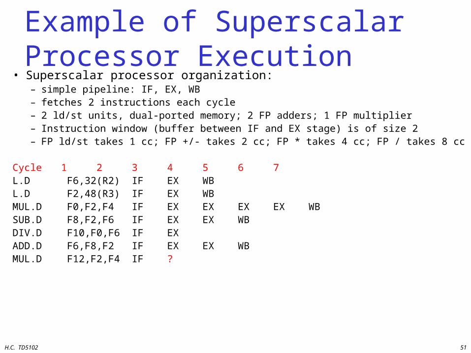
Example of Superscalar Processor Execution
• Superscalar processor organization:– simple pipeline: IF, EX, WB– fetches 2 instructions each cycle– 2 ld/st units, dual-ported memory; 2 FP adders; 1 FP multiplier– Instruction window (buffer between IF and EX stage) is of size 2– FP ld/st takes 1 cc; FP +/- takes 2 cc; FP * takes 4 cc; FP / takes 8 cc
Cycle 1 2 3 4 5 6 7L.D F6,32(R2) IF EX WBL.D F2,48(R3) IF EX WBMUL.D F0,F2,F4 IF EX EX EX EXSUB.D F8,F2,F6 IF EX EX WBDIV.D F10,F0,F6 IFADD.D F6,F8,F2 IF EX EXMUL.D F12,F2,F4 IF
cannot execute structural hazard
H.C. TD5102 51
Example of Superscalar Processor Execution
• Superscalar processor organization:– simple pipeline: IF, EX, WB– fetches 2 instructions each cycle– 2 ld/st units, dual-ported memory; 2 FP adders; 1 FP multiplier– Instruction window (buffer between IF and EX stage) is of size 2– FP ld/st takes 1 cc; FP +/- takes 2 cc; FP * takes 4 cc; FP / takes 8 cc
Cycle 1 2 3 4 5 6 7L.D F6,32(R2) IF EX WBL.D F2,48(R3) IF EX WBMUL.D F0,F2,F4 IF EX EX EX EX WBSUB.D F8,F2,F6 IF EX EX WBDIV.D F10,F0,F6 IF EXADD.D F6,F8,F2 IF EX EX WBMUL.D F12,F2,F4 IF ?
H.C. TD5102 52
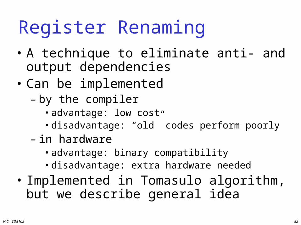
Register Renaming• A technique to eliminate anti- and output
dependencies• Can be implemented
– by the compiler• advantage: low cost• disadvantage: “old” codes perform poorly
– in hardware• advantage: binary compatibility• disadvantage: extra hardware needed
• Implemented in Tomasulo algorithm, but we describe general idea
H.C. TD5102 53
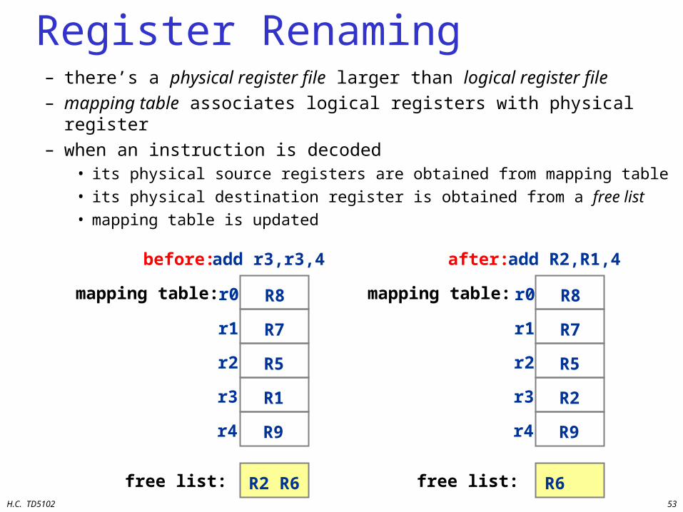
Register Renaming– there’s a physical register file larger than logical register file– mapping table associates logical registers with physical register– when an instruction is decoded
• its physical source registers are obtained from mapping table
• its physical destination register is obtained from a free list
• mapping table is updated
add r3,r3,4
R8
R7
R5
R1
R9
R2 R6
add R2,R1,4
R8
R7
R5
R2
R9
R6
before:
mapping table:
free list:
after:
mapping table:
free list:
r0
r1
r2
r3
r4
r0
r1
r2
r3
r4
H.C. TD5102 54
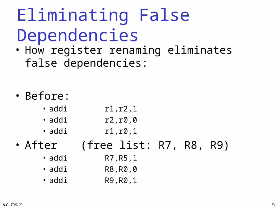
Eliminating False Dependencies• How register renaming eliminates false
dependencies:
• Before:• addi r1,r2,1• addi r2,r0,0• addi r1,r0,1
• After (free list: R7, R8, R9)• addi R7,R5,1• addi R8,R0,0• addi R9,R0,1
H.C. TD5102 55
Branch Prediction
H.C. TD5102 56
Branch PredictionMotivation
High branch penalties in pipelined processors:• With on average one out of five instructions
being a branch, the maximum ILP is five• Situation even worse for multiple-issue
processors, because we need to provide an instruction stream of n instructions per cycle.
• Idea: predict the outcome of branches based on their history and execute instructions speculatively
H.C. TD5102 57
5 Branch Prediction Schemes
1. 1-bit Branch Prediction Buffer
2. 2-bit Branch Prediction Buffer
3. Correlating Branch Prediction Buffer
4. Branch Target Buffer
5. Return Address Predictors
+ A way to get rid of those malicious branches
H.C. TD5102 58
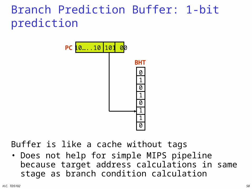
Branch Prediction Buffer: 1-bit prediction
Buffer is like a cache without tags• Does not help for simple MIPS pipeline because target
address calculations in same stage as branch condition calculation
10…..10 101 00
01010110
PC
BHT
H.C. TD5102 59
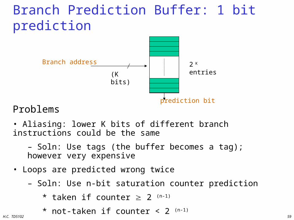
Branch Prediction Buffer: 1 bit prediction
Problems
• Aliasing: lower K bits of different branch instructions could be the same
– Soln: Use tags (the buffer becomes a tag); however very expensive
• Loops are predicted wrong twice
– Soln: Use n-bit saturation counter prediction
* taken if counter 2 (n-1)
* not-taken if counter < 2 (n-1)
– A 2 bit saturating counter predicts a loop wrong only once
Branch address 2 K entries
(K bits)
prediction bit
H.C. TD5102 60
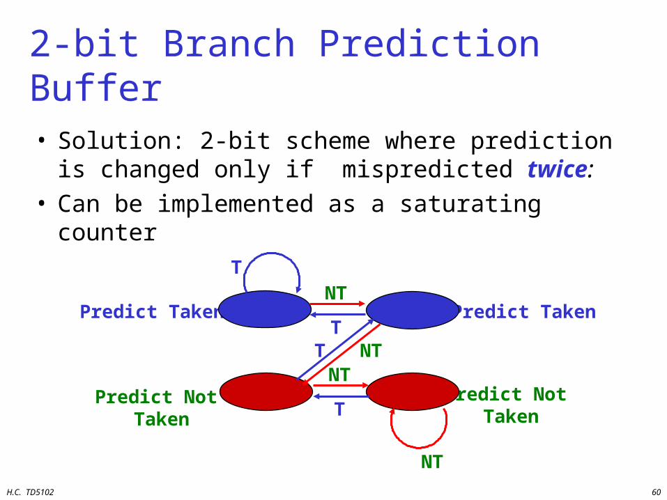
• Solution: 2-bit scheme where prediction is changed only if mispredicted twice:
• Can be implemented as a saturating counter
2-bit Branch Prediction Buffer
T
T
NT
Predict Taken
Predict Not Taken
Predict Taken
Predict Not TakenT
NT
T
NT
NT

H.C. TD5102 61
Correlating Branches
• Fragment from SPEC92 benchmark eqntott:
if (aa==2) subi R3,R1,#2
aa = 0; b1: bnez R3,L1
if (bb==2) add R1,R0,R0
bb=0; L1: subi R3,R2,#2
if (aa!=bb){ b2: bnez R3,L2
add R2,R0,R0
L2: sub R3,R1,R2
b3: beqz R3,L3
H.C. TD5102 62
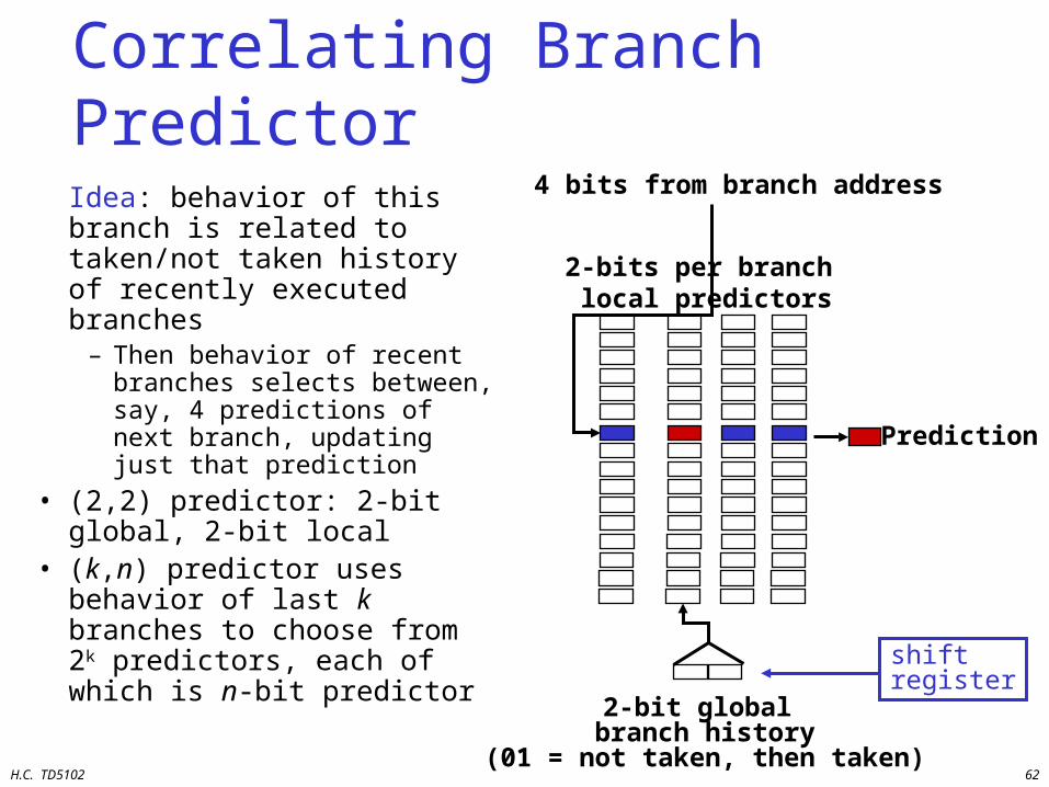
Correlating Branch Predictor
Idea: behavior of this branch is related to taken/not taken history of recently executed branches
– Then behavior of recent branches selects between, say, 4 predictions of next branch, updating just that prediction
• (2,2) predictor: 2-bit global, 2-bit local
• (k,n) predictor uses behavior of last k branches to choose from 2k predictors, each of which is n-bit predictor
4 bits from branch address
2-bits per branch local predictors
PredictionPrediction
2-bit global branch history
(01 = not taken, then taken)
shiftregister
H.C. TD5102 63
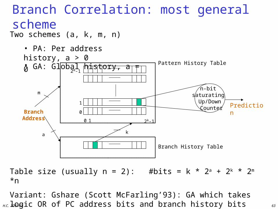
Branch Correlation: most general schemeTwo schemes (a, k, m, n)
• PA: Per address history, a > 0• GA: Global history, a = 0
n-bit saturating Up/Down Counter Prediction
Table size (usually n = 2): #bits = k * 2a + 2k * 2m *n
Variant: Gshare (Scott McFarling’93): GA which takes logic OR of PC address bits and branch history bits
Branch Address
0 1 2k-1
0
1
2m-1
Branch History Table
a k
m
Pattern History Table
H.C. TD5102 64
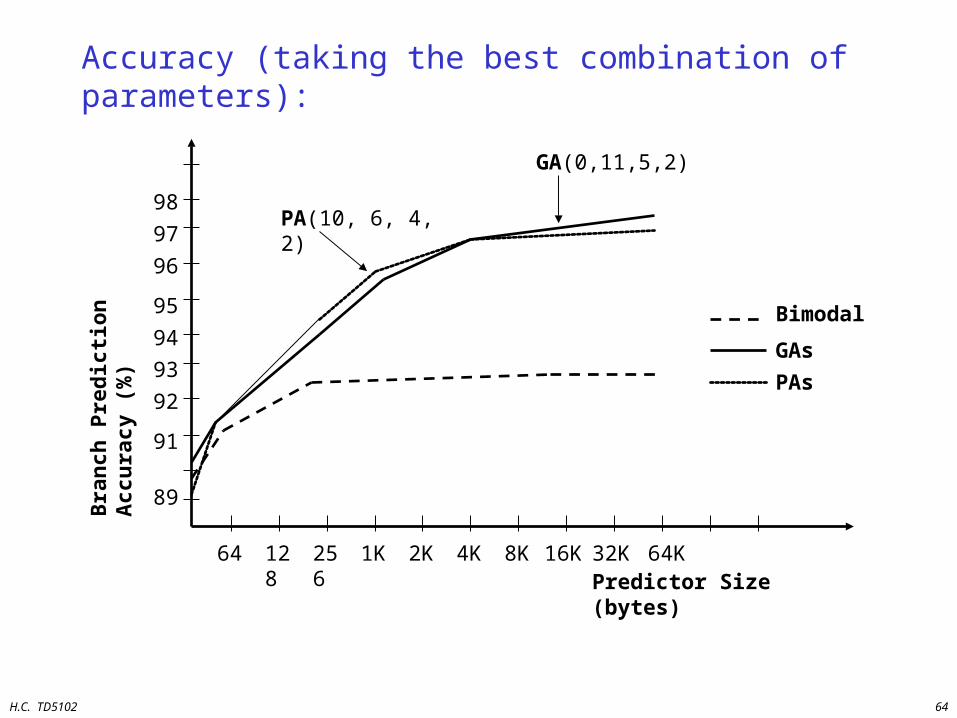
Accuracy (taking the best combination of parameters):
Predictor Size (bytes)64 128
Bra
nch
Pre
dic
tio
n A
ccu
racy
(%
)
256 1K 2K 4K 8K 16K 32K 64K
89
91
95
96
97
98
92
93
94
PA(10, 6, 4, 2)
GA(0,11,5,2)
Bimodal
GAs
PAs
H.C. TD5102 65
0%
1%
5%
6% 6%
11%
4%
6%
5%
1%
0%
2%
4%
6%
8%
10%
12%
14%
16%
18%
20%
nasa7 matrix300 tomcatv doducd spice fpppp gcc espresso eqntott li
Fre
quen
cy o
f M
ispre
dic
tions
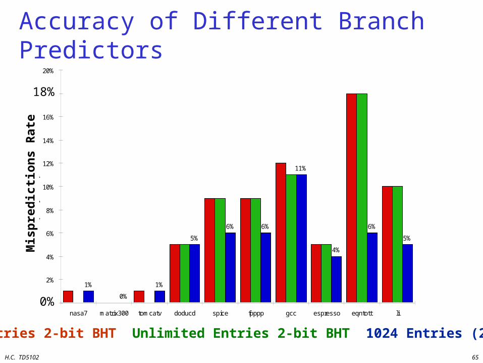
4,096 entries: 2-bits per entry Unlimited entries: 2-bits/entry 1,024 entries (2,2)
Accuracy of Different Branch Predictors
4096 Entries 2-bit BHT Unlimited Entries 2-bit BHT 1024 Entries (2,2) BHT
0%
Mis
pre
dic
tio
ns
Rat
e
18%
H.C. TD5102 66
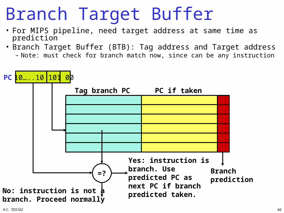
Branch Target Buffer• For MIPS pipeline, need target address at same time as
prediction• Branch Target Buffer (BTB): Tag address and Target address
– Note: must check for branch match now, since can be any instruction
Tag branch PC PC if taken
=? Branchprediction
Yes: instruction is branch. Use predicted PC as next PC if branch predicted taken.No: instruction is not a
branch. Proceed normally
10…..10 101 00PC
H.C. TD5102 67
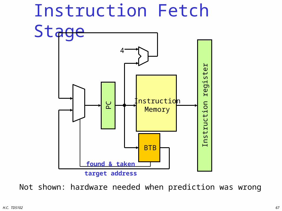
Instruction Fetch Stage
Not shown: hardware needed when prediction was wrong
InstructionMemoryP
C
Inst
ruct
ion
regi
ster
4
BTB
found & taken
target address
H.C. TD5102 68
Special Case: Return Addresses
• Register indirect branches: hard to predict target address– MIPS instruction: jr r31 // PC = r31
– useful for• implementing switch/case statements
• FORTRAN computed GOTOs
• procedure return (mainly)
• SPEC89: 85% such branches for procedure return
• Since stack discipline for procedures, save return address in small buffer that acts like a stack: 8 to 16 entries has small miss rate
H.C. TD5102 69
Dynamic Branch Prediction Summary
• Prediction becoming important part of scalar execution
• Branch History Table: 2 bits for loop accuracy• Correlation: Recently executed branches
correlated with next branch– Either different branches– Or different executions of same branch
• Branch Target Buffer: include branch target address & prediction
• Return address stack for prediction of indirect jumps
H.C. TD5102 70
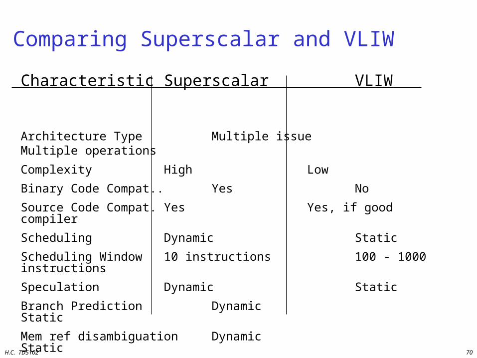
Comparing Superscalar and VLIW
Characteristic Superscalar VLIW
Architecture Type Multiple issue Multiple operations
Complexity High Low
Binary Code Compat.. Yes No
Source Code Compat. Yes Yes, if good compiler
Scheduling Dynamic Static
Scheduling Window 10 instructions 100 - 1000 instructions
Speculation Dynamic Static
Branch Prediction Dynamic Static
Mem ref disambiguation Dynamic Static
Scalability Medium High
Functional Flexibility High Very High
Application General Purpose Special Purpose
H.C. TD5102 71
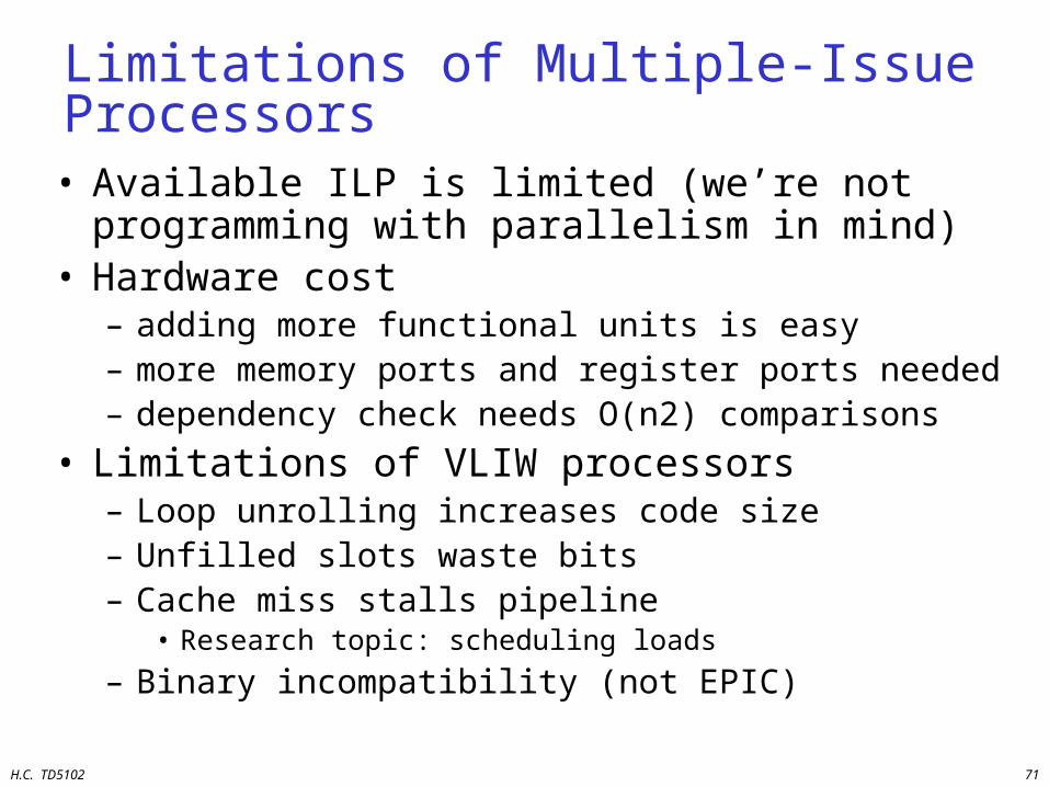
Limitations of Multiple-Issue Processors
• Available ILP is limited (we’re not programming with parallelism in mind)
• Hardware cost– adding more functional units is easy– more memory ports and register ports needed– dependency check needs O(n2) comparisons
• Limitations of VLIW processors– Loop unrolling increases code size– Unfilled slots waste bits– Cache miss stalls pipeline
• Research topic: scheduling loads
– Binary incompatibility (not EPIC)
H.C. TD5102 72
Overview
• Motivation and Goals
• Trends in Computer Architecture
• ILP Processors
• Transport Triggered Architectures
• Configurable components
• Summary and Conclusions

H.C. TD5102 73
Reducing Datapath Complexity: TTA
TTA: Transport Triggered ArchitectureOverview
Philosophy
MIRROR THE PROGRAMMING PARADIGM
• Program transports, operations are side effects of transports
• Compiler is in control of hardware transport capacity
H.C. TD5102 74
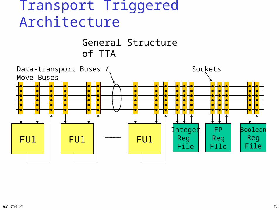
Transport Triggered Architecture
FU1 FU1 FU1IntegerReg File
FPRegFIle
BooleanRegFile
General Structure of TTA
Data-transport Buses / Move Buses Sockets
H.C. TD5102 75
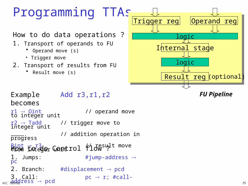
Programming TTAs
How to do data operations ?1. Transport of operands to FU
• Operand move (s)• Trigger move
2. Transport of results from FU• Result move (s)
How to do Control flow ?1. Jumps: #jump-address pc
2. Branch: #displacement pcd
3. Call: pc r; #call-address pcd
Example Add r3,r1,r2 becomesr1 Oint // operand move to integer unitr2 Tadd // trigger move to integer unit…………. // addition operation in progressRint r3 // result move from integer unit
FU Pipeline
Trigger reg Operand reg
logic
Internal stage
logic
Result reg (optional)
H.C. TD5102 76
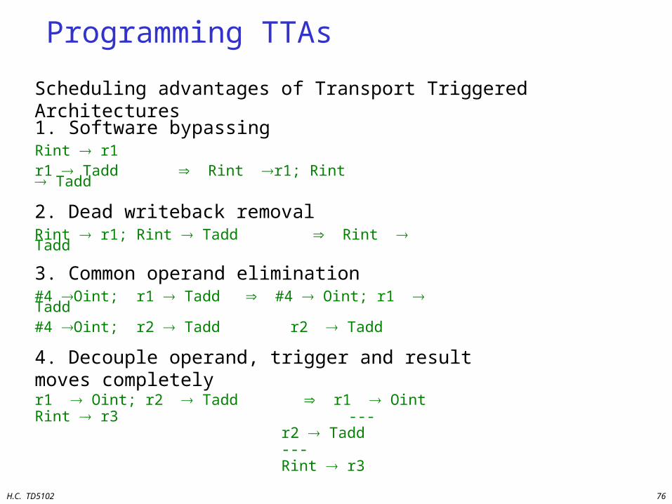
Programming TTAs
Scheduling advantages of Transport Triggered Architectures
1. Software bypassingRint r1r1 Tadd Rint r1; Rint Tadd
2. Dead writeback removalRint r1; Rint Tadd Rint Tadd
3. Common operand elimination#4 Oint; r1 Tadd #4 Oint; r1 Tadd#4 Oint; r2 Tadd r2 Tadd
4. Decouple operand, trigger and result moves completelyr1 Oint; r2 Tadd r1 OintRint r3 ---
r2 Tadd --- Rint r3
H.C. TD5102 77
TTA Advantages
Summary of advantages of TTAs
• Better usage of transport capacity– Instead of 3 transports per dyadic operation, about 2 are needed– # register ports reduced with at least 50%– Inter FU connectivity reduces with 50-70%
• No full connectivity required
• Both the transport capacity and # register ports become independent design parameters; this removes one of the major bottlenecks of VLIWs
• Flexible: FUs can incorporate arbitrary functionality• Scalable: #FUs, #reg.files, etc. can be changed• TTAs are easy to design and can have short cycle times
H.C. TD5102 78
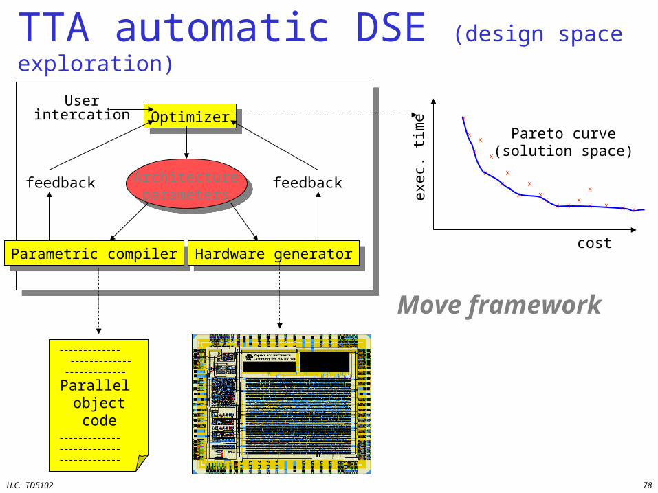
TTA automatic DSE (design space exploration)
Architectureparameters
OptimizerOptimizer
Parametric compilerParametric compiler Hardware generatorHardware generator
feedbackfeedback
Userintercation
Parallel object code chip
Pareto curve(solution space)
cost
exec
. tim
e
x
x
x
x
xx
x
xx
x
x
x
x
x
x
xx x
x
x
Move framework

H.C. TD5102 79
Overview
• Motivation and Goals
• Trends in Computer Architecture
• RISC processors
• ILP Processors
• Transport Triggered Architectures
• Configurable HW components
• Summary and Conclusions
H.C. TD5102 80
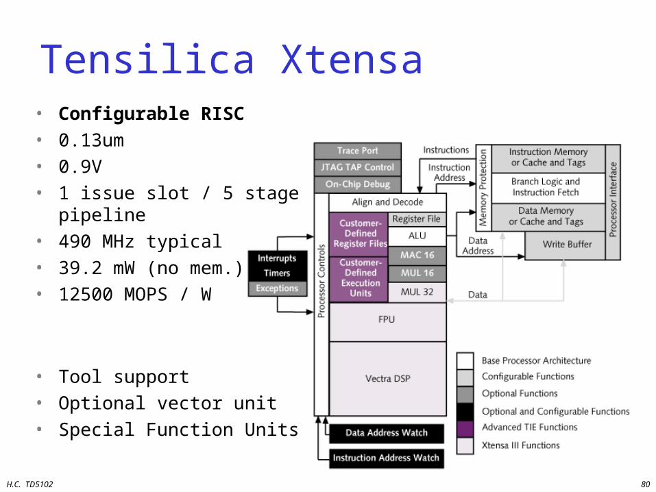
Tensilica Xtensa• Configurable RISC• 0.13um• 0.9V• 1 issue slot / 5 stage pipeline• 490 MHz typical• 39.2 mW (no mem.)• 12500 MOPS / W
• Tool support• Optional vector unit• Special Function Units
H.C. TD5102 81
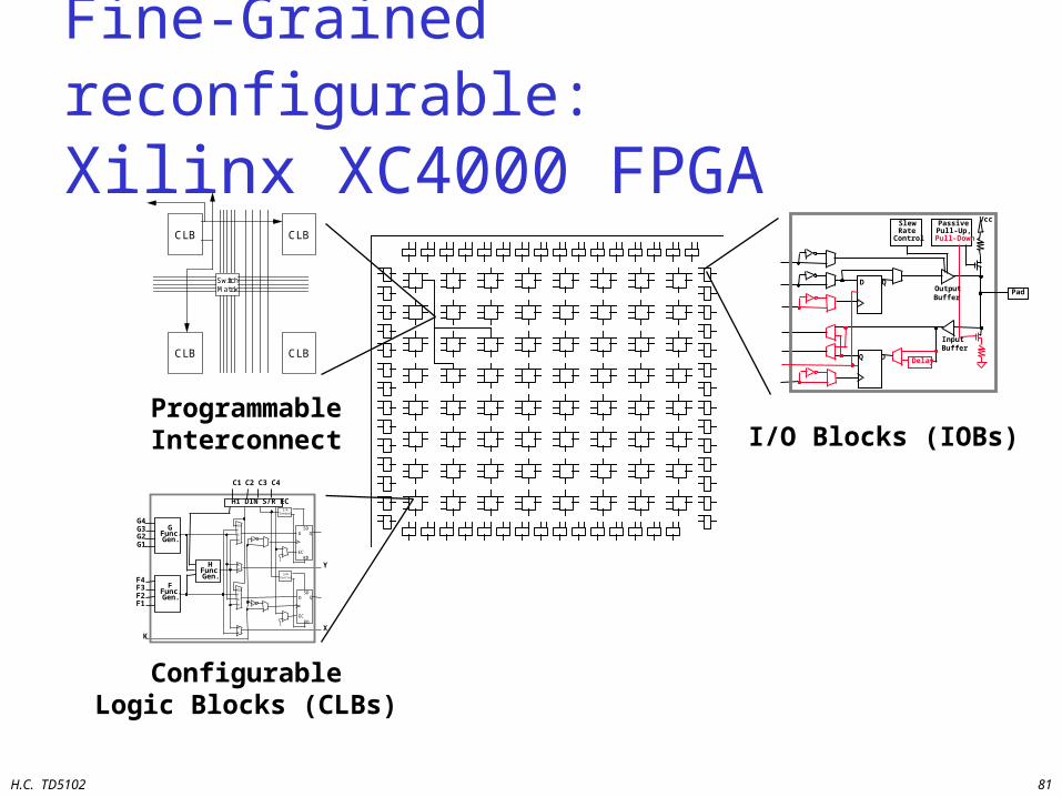
CLB
CLB
CLB
CLB
SwitchMatrix
ProgrammableInterconnect I/O Blocks (IOBs)
ConfigurableLogic Blocks (CLBs)
D Q
SlewRate
Control
PassivePull-Up,
Pull-Down
Delay
Vcc
OutputBuffer
InputBuffer
Q D
Pad
D QSD
RDEC
S/RControl
D QSD
RDEC
S/RControl
1
1
F'
G'
H'
DIN
F'
G'
H'
DIN
F'
G'
H'
H'
HFunc.Gen.
GFunc.Gen.
FFunc.Gen.
G4G3G2G1
F4F3F2F1
C4C1 C2 C3
K
Y
X
H1 DIN S/R EC
Fine-Grained reconfigurable: Xilinx XC4000 FPGA

H.C. TD5102 82
Coarse-Grained reconfigurable: Chameleon CS2000
Highlights:•32-bit datapath (ALU/Shift)•16x24 Multiplier•distributed local memory•fixed timing
H.C. TD5102 83
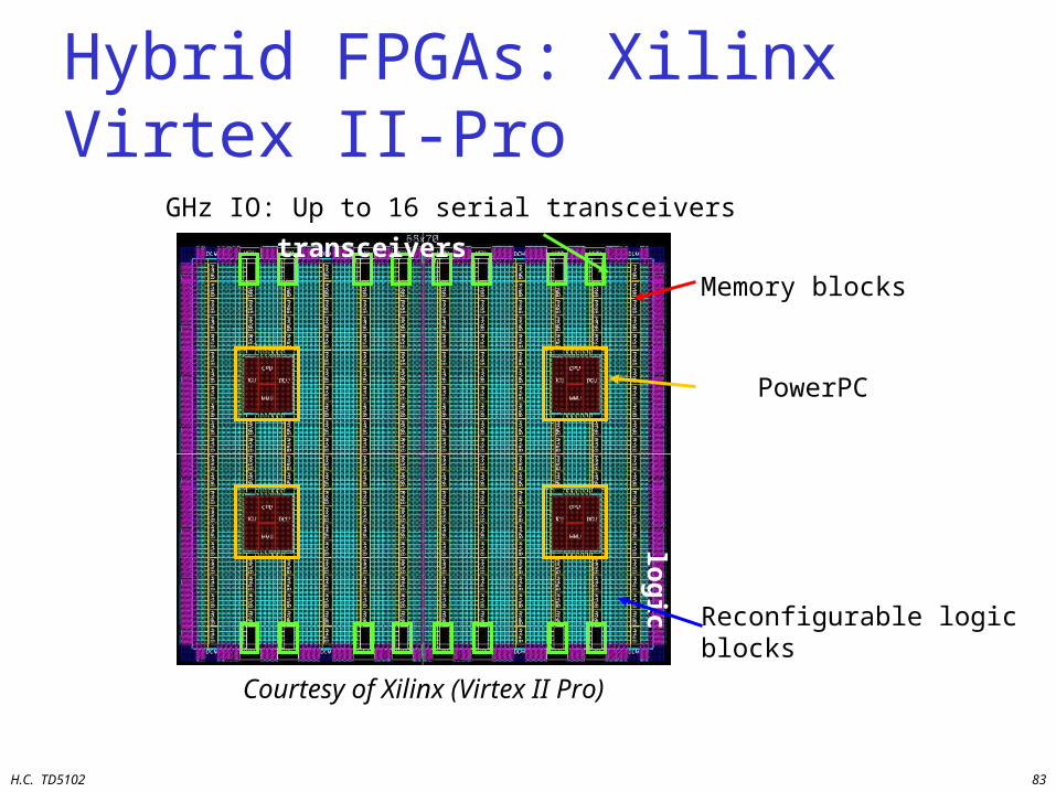
Hybrid FPGAs: Xilinx Virtex II-Pro
ReC
on
fig
.lo
gic
Pow
erP
Cs
Courtesy of Xilinx (Virtex II Pro)
PowerPC
Reconfigurable logicblocks
Memory blocks
Up to 16 serial transceiversGHz IO: Up to 16 serial transceivers
H.C. TD5102 84
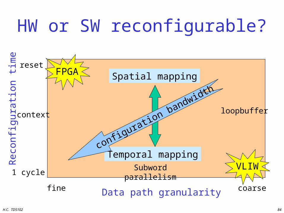
HW or SW reconfigurable?
Data path granularityfine coarse
Rec
onfi
gura
tion
tim
e
1 cycleSubword parallelism
loopbuffercontext
reset
Spatial mapping
Temporal mapping
FPGA
VLIW
configuration bandwidth

H.C. TD5102 85
Granularity Makes Differences
Fine-Grained Architecture
Coarse-Grained Architecture
Clock Speed Low High
Configuration Time
Long Short
Number of units High Low
Flexibility High Low
Power High Low
Area Large Small
H.C. TD5102 86
Overview
• Motivation and Goals
• Trends in Computer Architecture
• RISC processors
• ILP Processors
• Transport Triggered Architectures
• Configurable components
• Multi-threading
• Summary and Conclusions
H.C. TD5102 87
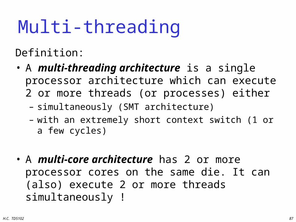
Multi-threadingDefinition: • A multi-threading architecture is a single
processor architecture which can execute 2 or more threads (or processes) either– simultaneously (SMT architecture)– with an extremely short context switch (1 or a few
cycles)
• A multi-core architecture has 2 or more processor cores on the same die. It can (also) execute 2 or more threads simultaneously !
H.C. TD5102 88
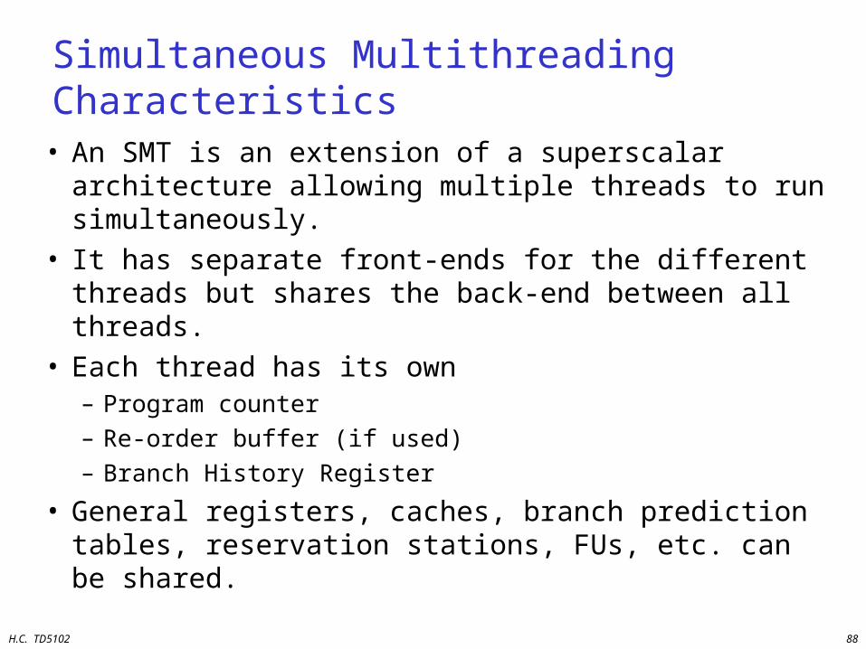
Simultaneous Multithreading Characteristics
• An SMT is an extension of a superscalar architecture allowing multiple threads to run simultaneously.
• It has separate front-ends for the different threads but shares the back-end between all threads.
• Each thread has its own– Program counter– Re-order buffer (if used)– Branch History Register
• General registers, caches, branch prediction tables, reservation stations, FUs, etc. can be shared.
H.C. TD5102 89
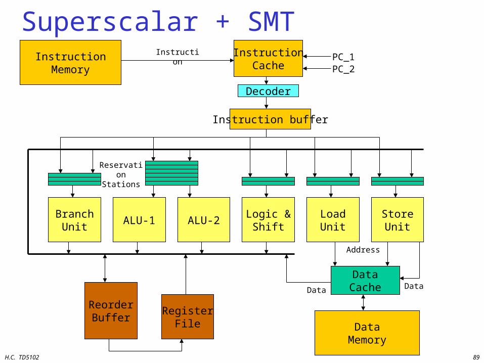
Superscalar + SMTInstructionMemory
InstructionCache
Decoder
BranchUnit
ALU-1 ALU-2Logic &
ShiftLoadUnit
StoreUnit
ReorderBuffer
RegisterFile
DataCache
DataMemory
Reservation Stations
Address
DataData
InstructionPC_1PC_2
Instruction buffer
H.C. TD5102 90
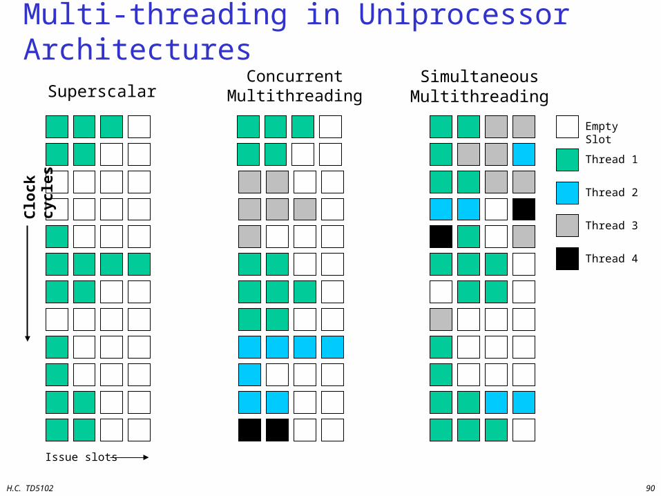
Multi-threading in Uniprocessor Architectures
SuperscalarSimultaneousMultithreading
ConcurrentMultithreading
Issue slots
Clo
ck c
ycle
s
Empty Slot
Thread 1
Thread 2
Thread 3
Thread 4
H.C. TD5102 91
Future Processors Components• New TriMedia
– VLIW with deeper pipeline, L1 and L2 cache, branch prediction.– used in SpaceCake cell
• Sony-IBM PS3 Cell architecture• Merrimac (Stanford; successor of Imagine):
– combines operation (VLIW) and data level parallelism (SIMD);
• TRIPS (Texas Austin / IBM) and SCALE (MIT) – processors combine task, operation and data level parallelism.
• Silicon Hife (Philips): – Coarse grain programmable kind of VLIW with many ALUs,
Multipliers,...
• See also, for many more architectures and platforms:– WWW Computer Architecture Page: www.cs.wisc.edu/~arch/www– HOT chips: www.hotchips.org (especially the archives)
H.C. TD5102 92
Summary and Conclusions
ILP architectures have great potential• Superscalars
– Binary compatible upgrade path
• VLIWs– Very flexible ASIPs
• TTAs– Avoid control and datapath bottlenecks– Completely compiler controlled– Very good cost-performance ratio– Low power
• Multi-threading– Surpass exploitable ILP in applications– How to choose threads ?
H.C. TD5102 93
What should you choose?Depends on:• application characteristics
– what types of parallelism can you exploit– what is a good memory hierarchy
• size of each level• bandwidth of each level
• performance requirements• energy budget• money budget• available tooling