Embed Size (px)
Citation preview
1
Embedded Systems Design: A Unified
Hardware/Software Introduction
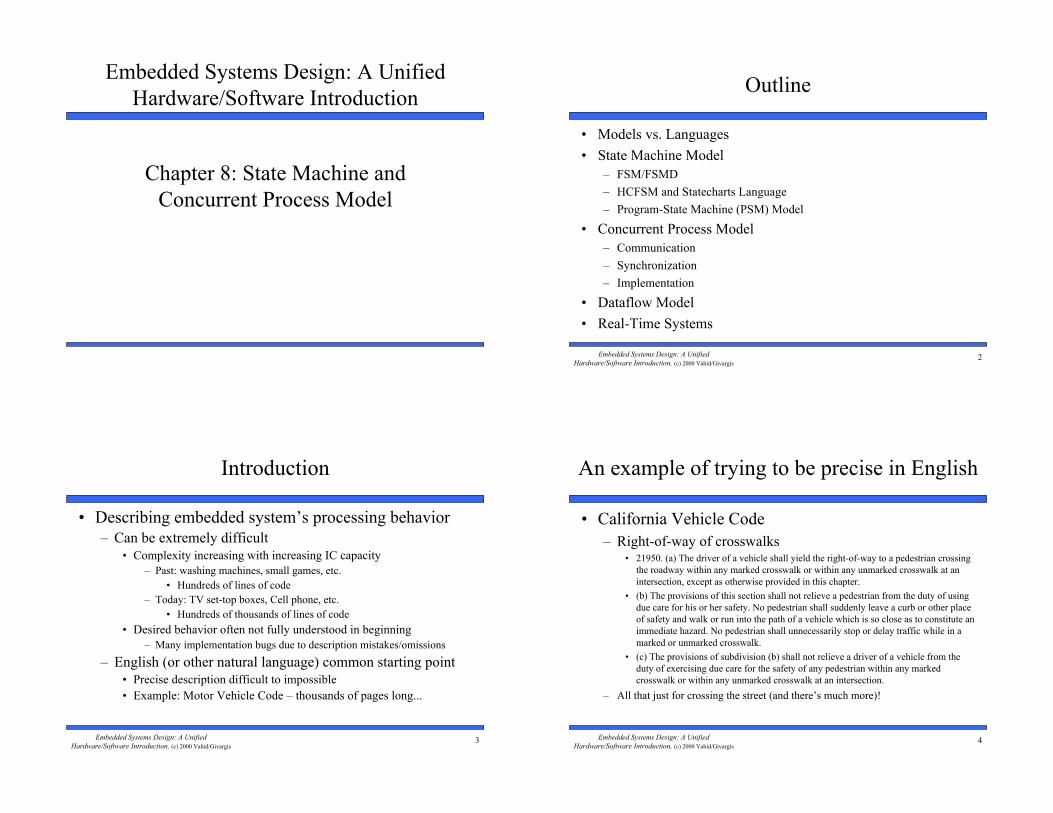
Chapter 8: State Machine and
Concurrent Process Model
2Embedded Systems Design: A Unified
Hardware/Software Introduction, (c) 2000 Vahid/Givargis
Outline
• Models vs. Languages
• State Machine Model
– FSM/FSMD
– HCFSM and Statecharts Language
– Program-State Machine (PSM) Model
• Concurrent Process Model
– Communication
– Synchronization
– Implementation
• Dataflow Model
• Real-Time Systems
3Embedded Systems Design: A Unified
Hardware/Software Introduction, (c) 2000 Vahid/Givargis
• Describing embedded system’s processing behavior
– Can be extremely difficult
• Complexity increasing with increasing IC capacity
– Past: washing machines, small games, etc.
• Hundreds of lines of code
– Today: TV set-top boxes, Cell phone, etc.
• Hundreds of thousands of lines of code
• Desired behavior often not fully understood in beginning
– Many implementation bugs due to description mistakes/omissions
– English (or other natural language) common starting point
• Precise description difficult to impossible
• Example: Motor Vehicle Code – thousands of pages long...
Introduction
4Embedded Systems Design: A Unified
Hardware/Software Introduction, (c) 2000 Vahid/Givargis
An example of trying to be precise in English
• California Vehicle Code
– Right-of-way of crosswalks• 21950. (a) The driver of a vehicle shall yield the right-of-way to a pedestrian crossing
the roadway within any marked crosswalk or within any unmarked crosswalk at an
intersection, except as otherwise provided in this chapter.
• (b) The provisions of this section shall not relieve a pedestrian from the duty of using
due care for his or her safety. No pedestrian shall suddenly leave a curb or other place
of safety and walk or run into the path of a vehicle which is so close as to constitute an
immediate hazard. No pedestrian shall unnecessarily stop or delay traffic while in a
marked or unmarked crosswalk.
• (c) The provisions of subdivision (b) shall not relieve a driver of a vehicle from the
duty of exercising due care for the safety of any pedestrian within any marked
crosswalk or within any unmarked crosswalk at an intersection.
– All that just for crossing the street (and there’s much more)!
5Embedded Systems Design: A Unified
Hardware/Software Introduction, (c) 2000 Vahid/Givargis
Models and languages
• How can we (precisely) capture behavior?
– We may think of languages (C, C++), but computation model is the key
• Common computation models:
– Sequential program model
• Statements, rules for composing statements, semantics for executing them
– Communicating process model
• Multiple sequential programs running concurrently
– State machine model
• For control dominated systems, monitors control inputs, sets control outputs
– Dataflow model
• For data dominated systems, transforms input data streams into output streams
– Object-oriented model
• For breaking complex software into simpler, well-defined pieces
6Embedded Systems Design: A Unified
Hardware/Software Introduction, (c) 2000 Vahid/Givargis
Models vs. languages
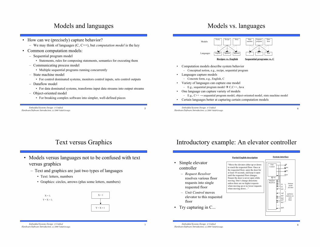
• Computation models describe system behavior
– Conceptual notion, e.g., recipe, sequential program
• Languages capture models
– Concrete form, e.g., English, C
• Variety of languages can capture one model
– E.g., sequential program model ! C,C++, Java
• One language can capture variety of models
– E.g., C++ ! sequential program model, object-oriented model, state machine model
• Certain languages better at capturing certain computation models
Models
Languages
Recipe
SpanishEnglish Japanese
Poetry Story Sequent.
program
C++C Java
State
machine
Data-
flow
Recipes vs. English Sequential programs vs. C
7Embedded Systems Design: A Unified
Hardware/Software Introduction, (c) 2000 Vahid/Givargis
Text versus Graphics
• Models versus languages not to be confused with text
versus graphics
– Text and graphics are just two types of languages
• Text: letters, numbers
• Graphics: circles, arrows (plus some letters, numbers)
X = 1;
Y = X + 1;
X = 1
Y = X + 1
8Embedded Systems Design: A Unified
Hardware/Software Introduction, (c) 2000 Vahid/Givargis
Introductory example: An elevator controller
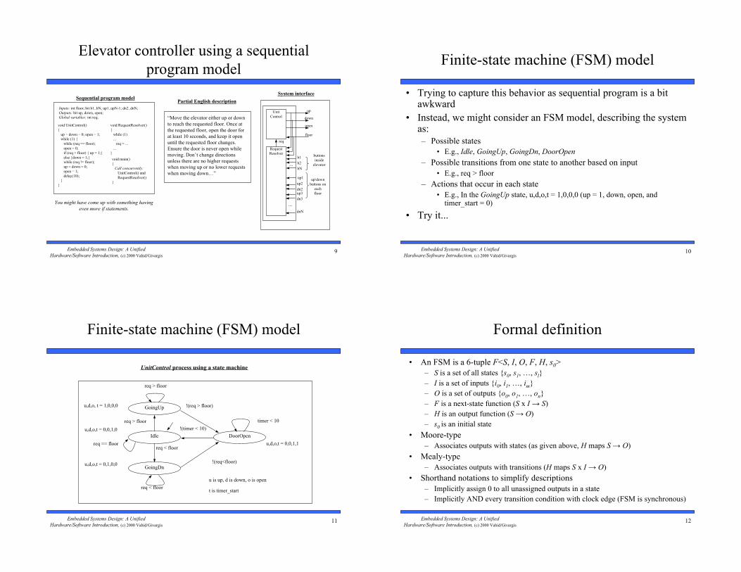
• Simple elevator
controller
– Request Resolver
resolves various floor
requests into single
requested floor
– Unit Control moves
elevator to this requested
floor
• Try capturing in C...
“Move the elevator either up or down
to reach the requested floor. Once at
the requested floor, open the door for
at least 10 seconds, and keep it open
until the requested floor changes.
Ensure the door is never open while
moving. Don’t change directions
unless there are no higher requests
when moving up or no lower requests
when moving down…”
Partial English description
buttons
inside
elevator
Unit
Control
b1
down
open
floor
...
Request
Resolver
...
up/down
buttons on
each
floor
b2
bN
up1
up2
dn2
dnN
req
up
System interface
up3
dn3
9Embedded Systems Design: A Unified
Hardware/Software Introduction, (c) 2000 Vahid/Givargis
Elevator controller using a sequential
program model
“Move the elevator either up or down
to reach the requested floor. Once at
the requested floor, open the door for
at least 10 seconds, and keep it open
until the requested floor changes.
Ensure the door is never open while
moving. Don’t change directions
unless there are no higher requests
when moving up or no lower requests
when moving down…”
Partial English description
buttons
inside
elevator
Unit
Control
b1
down
open
floor
...
Request
Resolver
...
up/down
buttons on
each
floor
b2
bN
up1
up2
dn2
dnN
req
up
System interface
up3
dn3
Sequential program model
void UnitControl()
{
up = down = 0; open = 1;
while (1) {
while (req == floor);
open = 0;
if (req > floor) { up = 1;}
else {down = 1;}
while (req != floor);
up = down = 0;
open = 1;
delay(10);
}
}
void RequestResolver()
{
while (1)
...
req = ...
...
}
void main()
{
Call concurrently:
UnitControl() and
RequestResolver()
}
Inputs: int floor; bit b1..bN; up1..upN-1; dn2..dnN;
Outputs: bit up, down, open;
Global variables: int req;
You might have come up with something having
even more if statements.
10Embedded Systems Design: A Unified
Hardware/Software Introduction, (c) 2000 Vahid/Givargis
Finite-state machine (FSM) model
• Trying to capture this behavior as sequential program is a bitawkward
• Instead, we might consider an FSM model, describing the systemas:
– Possible states
• E.g., Idle, GoingUp, GoingDn, DoorOpen
– Possible transitions from one state to another based on input
• E.g., req > floor
– Actions that occur in each state
• E.g., In the GoingUp state, u,d,o,t = 1,0,0,0 (up = 1, down, open, andtimer_start = 0)
• Try it...
11Embedded Systems Design: A Unified
Hardware/Software Introduction, (c) 2000 Vahid/Givargis
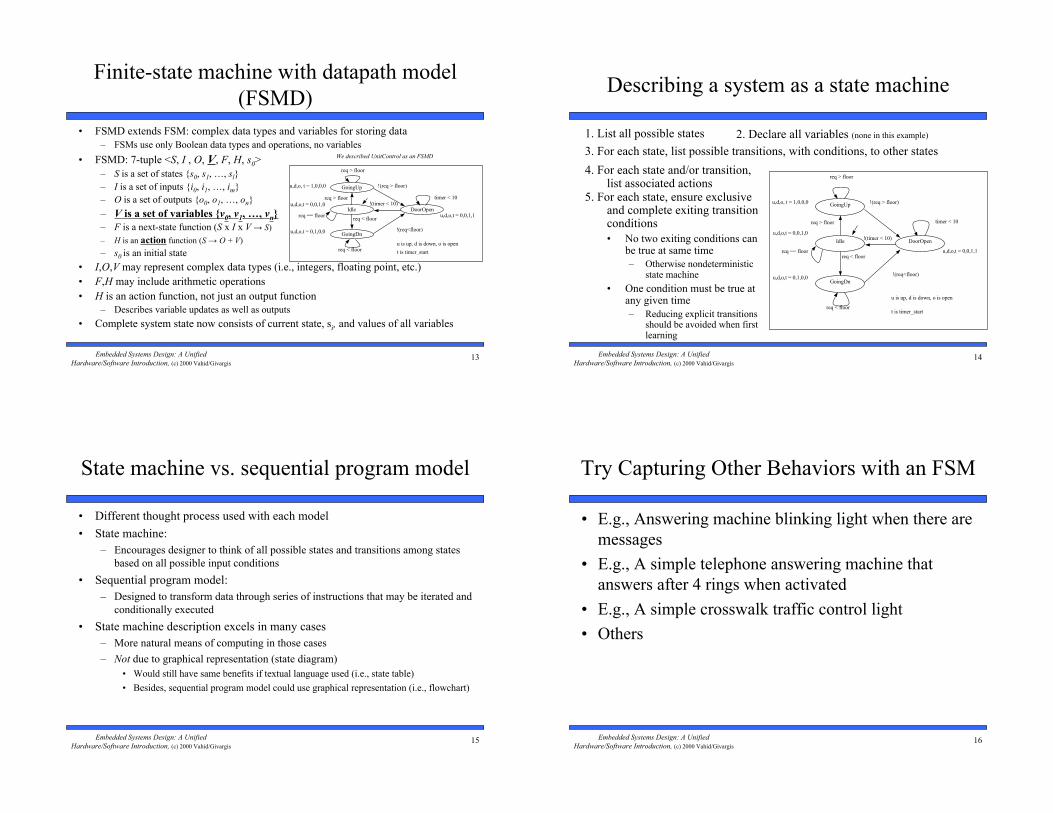
Finite-state machine (FSM) model
Idle
GoingUp
req > floor
req < floor
!(req > floor)
!(timer < 10)
req < floor
DoorOpen
GoingDn
req > floor
u,d,o, t = 1,0,0,0
u,d,o,t = 0,0,1,0
u,d,o,t = 0,1,0,0
u,d,o,t = 0,0,1,1
u is up, d is down, o is open
req == floor
!(req<floor)
timer < 10
t is timer_start
UnitControl process using a state machine
12Embedded Systems Design: A Unified
Hardware/Software Introduction, (c) 2000 Vahid/Givargis
Formal definition
• An FSM is a 6-tuple F<S, I, O, F, H, s0>
– S is a set of all states {s0, s1, …, sl}
– I is a set of inputs {i0, i1, …, im}
– O is a set of outputs {o0, o1, …, on}
– F is a next-state function (S x I ! S)
– H is an output function (S ! O)
– s0 is an initial state
• Moore-type
– Associates outputs with states (as given above, H maps S ! O)
• Mealy-type
– Associates outputs with transitions (H maps S x I ! O)
• Shorthand notations to simplify descriptions
– Implicitly assign 0 to all unassigned outputs in a state
– Implicitly AND every transition condition with clock edge (FSM is synchronous)
13Embedded Systems Design: A Unified
Hardware/Software Introduction, (c) 2000 Vahid/Givargis
Finite-state machine with datapath model
(FSMD)
• FSMD extends FSM: complex data types and variables for storing data
– FSMs use only Boolean data types and operations, no variables
• FSMD: 7-tuple <S, I , O, V, F, H, s0>
– S is a set of states {s0, s1, …, sl}
– I is a set of inputs {i0, i1, …, im}
– O is a set of outputs {o0, o1, …, on}
– V is a set of variables {v0, v1, …, vn}
– F is a next-state function (S x I x V ! S)
– H is an action function (S ! O + V)
– s0 is an initial state
• I,O,V may represent complex data types (i.e., integers, floating point, etc.)
• F,H may include arithmetic operations
• H is an action function, not just an output function
– Describes variable updates as well as outputs
• Complete system state now consists of current state, si, and values of all variables
Idle
GoingUp
req > floor
req < floor
!(req > floor)
!(timer < 10)
req < floor
DoorOpen
GoingDn
req > floor
u,d,o, t = 1,0,0,0
u,d,o,t = 0,0,1,0
u,d,o,t = 0,1,0,0
u,d,o,t = 0,0,1,1
u is up, d is down, o is open
req == floor
!(req<floor)
timer < 10
t is timer_start
We described UnitControl as an FSMD
14Embedded Systems Design: A Unified
Hardware/Software Introduction, (c) 2000 Vahid/Givargis
Describing a system as a state machine
1. List all possible states 2. Declare all variables (none in this example)
3. For each state, list possible transitions, with conditions, to other states
4. For each state and/or transition,list associated actions
5. For each state, ensure exclusiveand complete exiting transitionconditions
• No two exiting conditions canbe true at same time
– Otherwise nondeterministicstate machine
• One condition must be true atany given time
– Reducing explicit transitionsshould be avoided when firstlearning
req > floor
!(req > floor)u,d,o, t = 1,0,0,0
u,d,o,t = 0,0,1,0
u,d,o,t = 0,1,0,0
u,d,o,t = 0,0,1,1
u is up, d is down, o is open
req < floor
req > floor
req == floor
req < floor
!(req<floor)
!(timer < 10)
timer < 10
t is timer_start
Idle
GoingUp
DoorOpen
GoingDn
15Embedded Systems Design: A Unified
Hardware/Software Introduction, (c) 2000 Vahid/Givargis
State machine vs. sequential program model
• Different thought process used with each model
• State machine:
– Encourages designer to think of all possible states and transitions among states
based on all possible input conditions
• Sequential program model:
– Designed to transform data through series of instructions that may be iterated and
conditionally executed
• State machine description excels in many cases
– More natural means of computing in those cases
– Not due to graphical representation (state diagram)
• Would still have same benefits if textual language used (i.e., state table)
• Besides, sequential program model could use graphical representation (i.e., flowchart)
16Embedded Systems Design: A Unified
Hardware/Software Introduction, (c) 2000 Vahid/Givargis
Try Capturing Other Behaviors with an FSM
• E.g., Answering machine blinking light when there are
messages
• E.g., A simple telephone answering machine that
answers after 4 rings when activated
• E.g., A simple crosswalk traffic control light
• Others
17Embedded Systems Design: A Unified
Hardware/Software Introduction, (c) 2000 Vahid/Givargis
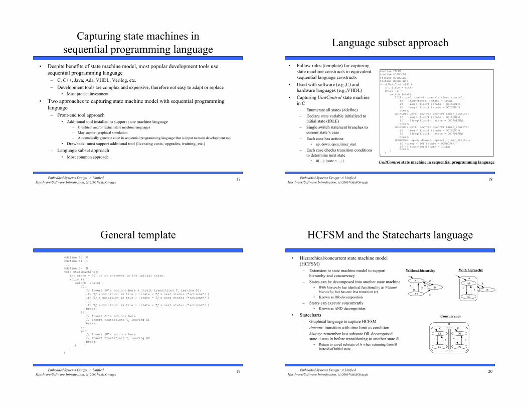
Capturing state machines in
sequential programming language
• Despite benefits of state machine model, most popular development tools use
sequential programming language
– C, C++, Java, Ada, VHDL, Verilog, etc.
– Development tools are complex and expensive, therefore not easy to adapt or replace
• Must protect investment
• Two approaches to capturing state machine model with sequential programming
language
– Front-end tool approach
• Additional tool installed to support state machine language
– Graphical and/or textual state machine languages
– May support graphical simulation
– Automatically generate code in sequential programming language that is input to main development tool
• Drawback: must support additional tool (licensing costs, upgrades, training, etc.)
– Language subset approach
• Most common approach...
18Embedded Systems Design: A Unified
Hardware/Software Introduction, (c) 2000 Vahid/Givargis
Language subset approach
• Follow rules (template) for capturing
state machine constructs in equivalent
sequential language constructs
• Used with software (e.g.,C) and
hardware languages (e.g.,VHDL)
• Capturing UnitControl state machine
in C
– Enumerate all states (#define)
– Declare state variable initialized to
initial state (IDLE)
– Single switch statement branches to
current state’s case
– Each case has actions
• up, down, open, timer_start
– Each case checks transition conditions
to determine next state
• if(…) {state = …;}
#define IDLE0#define GOINGUP1#define GOINGDN2#define DOOROPEN3void UnitControl() { int state = IDLE; while (1) { switch (state) { IDLE: up=0; down=0; open=1; timer_start=0; if (req==floor) {state = IDLE;} if (req > floor) {state = GOINGUP;} if (req < floor) {state = GOINGDN;} break; GOINGUP: up=1; down=0; open=0; timer_start=0; if (req > floor) {state = GOINGUP;} if (!(req>floor)) {state = DOOROPEN;} break; GOINGDN: up=1; down=0; open=0; timer_start=0; if (req < floor) {state = GOINGDN;} if (!(req<floor)) {state = DOOROPEN;} break; DOOROPEN: up=0; down=0; open=1; timer_start=1; if (timer < 10) {state = DOOROPEN;} if (!(timer<10)){state = IDLE;} break; } }}
UnitControl state machine in sequential programming language
19Embedded Systems Design: A Unified
Hardware/Software Introduction, (c) 2000 Vahid/Givargis
General template
#define S0 0#define S1 1...#define SN Nvoid StateMachine() { int state = S0; // or whatever is the initial state. while (1) { switch (state) { S0: // Insert S0’s actions here & Insert transitions Ti leaving S0: if( T0’s condition is true ) {state = T0’s next state; /*actions*/ } if( T1’s condition is true ) {state = T1’s next state; /*actions*/ } ... if( Tm’s condition is true ) {state = Tm’s next state; /*actions*/ } break; S1: // Insert S1’s actions here // Insert transitions Ti leaving S1 break; ... SN: // Insert SN’s actions here // Insert transitions Ti leaving SN break; } }}
20Embedded Systems Design: A Unified
Hardware/Software Introduction, (c) 2000 Vahid/Givargis
HCFSM and the Statecharts language
• Hierarchical/concurrent state machine model
(HCFSM)
– Extension to state machine model to support
hierarchy and concurrency
– States can be decomposed into another state machine
• With hierarchy has identical functionality as Without
hierarchy, but has one less transition (z)
• Known as OR-decomposition
– States can execute concurrently
• Known as AND-decomposition
• Statecharts
– Graphical language to capture HCFSM
– timeout: transition with time limit as condition
– history: remember last substate OR-decomposed
state A was in before transitioning to another state B
• Return to saved substate of A when returning from B
instead of initial state
A1 z
B
A2 z
xy
w
Without hierarchy
A1 z
B
A2
x y
A
w
With hierarchy
C1
C2
x y
C
B
D1
D2
u v
D
Concurrency

21Embedded Systems Design: A Unified
Hardware/Software Introduction, (c) 2000 Vahid/Givargis
UnitControl with FireMode
• FireMode
– When fire is true, move elevatorto 1st floor and open door
Without hierarchy
Idle
GoingUp
req>floor
req<floor
!(req>floor)
timeout(10)
req<floor
DoorOpen
GoingDn
req>floor
u,d,o = 1,0,0
u,d,o = 0,0,1
u,d,o = 0,1,0
req==floor!(req<floor)
firefire
firefire
FireGoingDn
floor>1
u,d,o = 0,1,0
u,d,o = 0,0,1
!fire
FireDrOpen
floor==1
fire
u,d,o = 0,0,1
UnitControl
fire
!fireFireGoingDn
floor>1
u,d,o = 0,1,0
FireDrOpen
floor==1
fire
FireMode
u,d,o = 0,0,1
With hierarchy
Idle
GoingUp
req>floor
req<floor
!(req>floor)
timeout(10)
req<floor
DoorOpen
GoingDn
req>floor
u,d,o = 1,0,0
u,d,o = 0,0,1
u,d,o = 0,1,0
req==floor!(req>floor)
u,d,o = 0,0,1
NormalMode
UnitControl
NormalMode
FireMode
fire!fire
UnitControl
ElevatorController
RequestResolver
...
With concurrent RequestResolver
– w/o hierarchy: Getting messy!
– w/ hierarchy: Simple!
22Embedded Systems Design: A Unified
Hardware/Software Introduction, (c) 2000 Vahid/Givargis
Program-state machine model (PSM):
HCFSM plus sequential program model
• Program-state’s actions can be FSM orsequential program
– Designer can choose most appropriate
• Stricter hierarchy than HCFSM used inStatecharts
– transition between sibling states only, single entry
– Program-state may “complete”
• Reaches end of sequential program code, OR
• FSM transition to special complete substate
• PSM has 2 types of transitions
– Transition-immediately (TI): taken regardless ofsource program-state
– Transition-on-completion (TOC): taken only ifcondition is true AND source program-state iscomplete
– SpecCharts: extension of VHDL to capture PSMmodel
– SpecC: extension of C to capture PSM model
up = down = 0; open = 1;
while (1) {
while (req == floor);
open = 0;
if (req > floor) { up = 1;}
else {down = 1;}
while (req != floor);
open = 1;
delay(10);
}
}
NormalMode
FireMode
up = 0; down = 1; open = 0;
while (floor > 1);
up = 0; down = 0; open = 1;
fire!fire
UnitControl
ElevatorController
RequestResolver
...
req = ...
...
int req;
• NormalMode and FireMode described as
sequential programs
• Black square originating within FireMode
indicates !fire is a TOC transition
– Transition from FireMode to NormalMode
only after FireMode completed
23Embedded Systems Design: A Unified
Hardware/Software Introduction, (c) 2000 Vahid/Givargis
Role of appropriate model and language
• Finding appropriate model to capture embedded system is an important step
– Model shapes the way we think of the system
• Originally thought of sequence of actions, wrote sequential program
– First wait for requested floor to differ from target floor
– Then, we close the door
– Then, we move up or down to the desired floor
– Then, we open the door
– Then, we repeat this sequence
• To create state machine, we thought in terms of states and transitions among states
– When system must react to changing inputs, state machine might be best model
• HCFSM described FireMode easily, clearly
• Language should capture model easily
– Ideally should have features that directly capture constructs of model
– FireMode would be very complex in sequential program
• Checks inserted throughout code
– Other factors may force choice of different model
• Structured techniques can be used instead
– E.g., Template for state machine capture in sequential program language
24Embedded Systems Design: A Unified
Hardware/Software Introduction, (c) 2000 Vahid/Givargis
Concurrent process model
• Describes functionality of system in terms of two or more
concurrently executing subtasks
• Many systems easier to describe with concurrent process model
because inherently multitasking
• E.g., simple example:
– Read two numbers X and Y
– Display “Hello world.” every X seconds
– Display “How are you?” every Y seconds
• More effort would be required with sequential program or state
machine model
Subroutine execution over time
time
ReadX ReadY
PrintHelloWorld
PrintHowAreYou
Simple concurrent process example
ConcurrentProcessExample() { x = ReadX() y = ReadY() Call concurrently: PrintHelloWorld(x) and PrintHowAreYou(y)}PrintHelloWorld(x) { while( 1 ) { print "Hello world." delay(x); }}PrintHowAreYou(x) { while( 1 ) { print "How are you?" delay(y); }}
Sample input and output
Enter X: 1Enter Y: 2Hello world. (Time = 1 s)Hello world. (Time = 2 s)How are you? (Time = 2 s)Hello world. (Time = 3 s)How are you? (Time = 4 s)Hello world. (Time = 4 s)...
25Embedded Systems Design: A Unified
Hardware/Software Introduction, (c) 2000 Vahid/Givargis
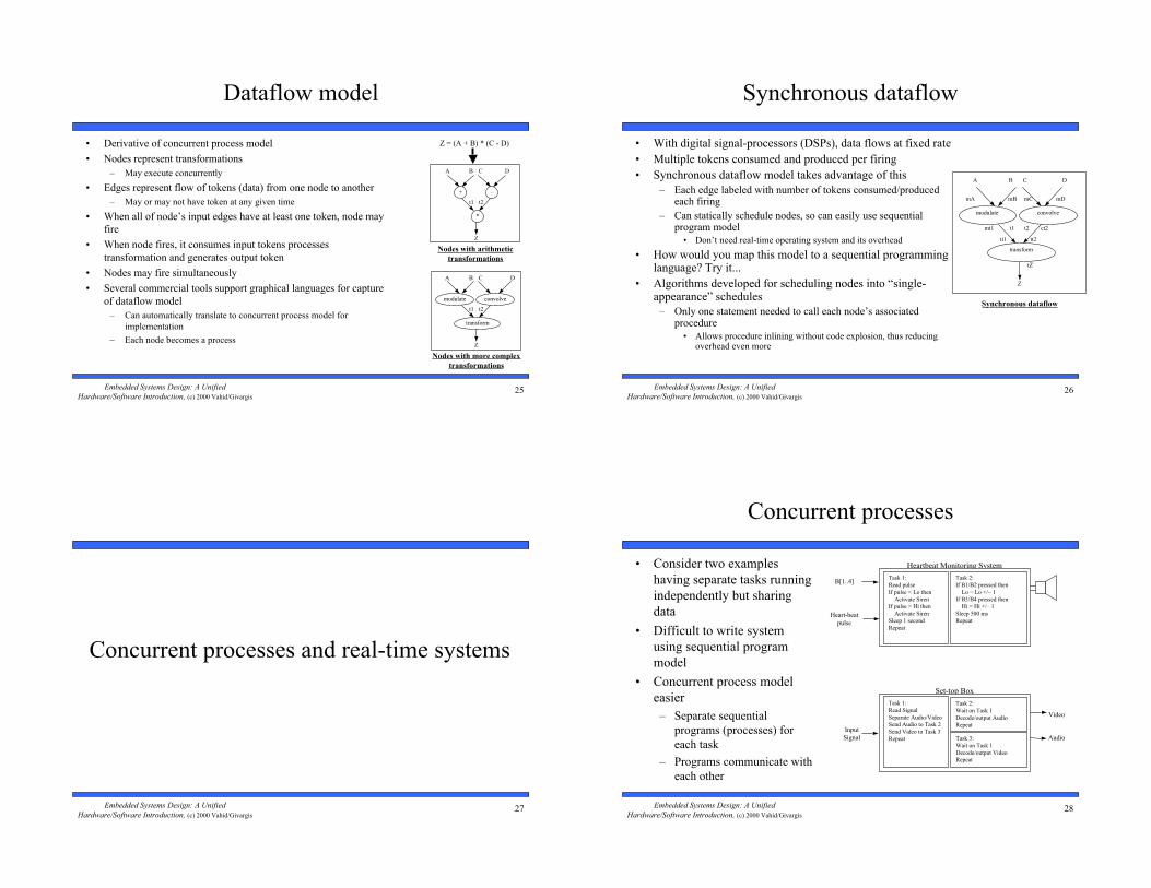
Dataflow model
• Derivative of concurrent process model
• Nodes represent transformations
– May execute concurrently
• Edges represent flow of tokens (data) from one node to another
– May or may not have token at any given time
• When all of node’s input edges have at least one token, node may
fire
• When node fires, it consumes input tokens processes
transformation and generates output token
• Nodes may fire simultaneously
• Several commercial tools support graphical languages for capture
of dataflow model
– Can automatically translate to concurrent process model for
implementation
– Each node becomes a process
modulate convolve
transform
A B C D
Z
Nodes with more complex
transformations
t1 t2
+ –
*
A B C D
Z
Nodes with arithmetic
transformations
t1 t2
Z = (A + B) * (C - D)
26Embedded Systems Design: A Unified
Hardware/Software Introduction, (c) 2000 Vahid/Givargis
Synchronous dataflow
• With digital signal-processors (DSPs), data flows at fixed rate
• Multiple tokens consumed and produced per firing
• Synchronous dataflow model takes advantage of this
– Each edge labeled with number of tokens consumed/producedeach firing
– Can statically schedule nodes, so can easily use sequentialprogram model
• Don’t need real-time operating system and its overhead
• How would you map this model to a sequential programminglanguage? Try it...
• Algorithms developed for scheduling nodes into “single-appearance” schedules
– Only one statement needed to call each node’s associatedprocedure
• Allows procedure inlining without code explosion, thus reducingoverhead even more
modulate convolve
transform
A B C D
Z
Synchronous dataflow
mt1 ct2
mA mB mC mD
tZ
tt1 tt2
t1 t2
27Embedded Systems Design: A Unified
Hardware/Software Introduction, (c) 2000 Vahid/Givargis
Concurrent processes and real-time systems
28Embedded Systems Design: A Unified
Hardware/Software Introduction, (c) 2000 Vahid/Givargis
Concurrent processes
• Consider two examples
having separate tasks running
independently but sharing
data
• Difficult to write system
using sequential program
model
• Concurrent process model
easier
– Separate sequential
programs (processes) for
each task
– Programs communicate with
each other
Heartbeat Monitoring System
B[1..4]
Heart-beat
pulse
Task 1:
Read pulse
If pulse < Lo then
Activate Siren
If pulse > Hi then
Activate Siren
Sleep 1 second
Repeat
Task 2:
If B1/B2 pressed then
Lo = Lo +/– 1
If B3/B4 pressed then
Hi = Hi +/– 1
Sleep 500 ms
Repeat
Set-top Box
Input
Signal
Task 1:
Read Signal
Separate Audio/Video
Send Audio to Task 2
Send Video to Task 3
Repeat
Task 2:
Wait on Task 1
Decode/output Audio
Repeat
Task 3:
Wait on Task 1
Decode/output Video
Repeat
Video
Audio
29Embedded Systems Design: A Unified
Hardware/Software Introduction, (c) 2000 Vahid/Givargis
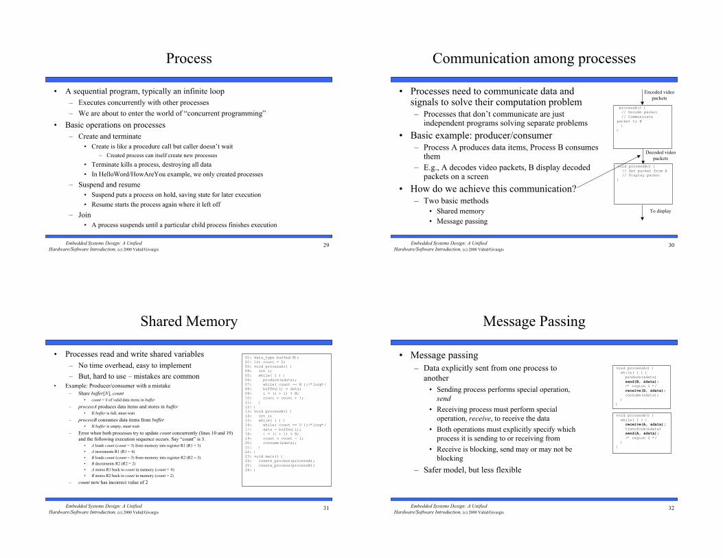
Process
• A sequential program, typically an infinite loop
– Executes concurrently with other processes
– We are about to enter the world of “concurrent programming”
• Basic operations on processes
– Create and terminate
• Create is like a procedure call but caller doesn’t wait
– Created process can itself create new processes
• Terminate kills a process, destroying all data
• In HelloWord/HowAreYou example, we only created processes
– Suspend and resume
• Suspend puts a process on hold, saving state for later execution
• Resume starts the process again where it left off
– Join
• A process suspends until a particular child process finishes execution
30Embedded Systems Design: A Unified
Hardware/Software Introduction, (c) 2000 Vahid/Givargis
Communication among processes
• Processes need to communicate data andsignals to solve their computation problem
– Processes that don’t communicate are justindependent programs solving separate problems
• Basic example: producer/consumer
– Process A produces data items, Process B consumesthem
– E.g., A decodes video packets, B display decodedpackets on a screen
• How do we achieve this communication?
– Two basic methods
• Shared memory
• Message passing
processA() { // Decode packet // Communicatepacket to B }}
void processB() { // Get packet from A // Display packet}
Encoded video
packets
Decoded video
packets
To display
31Embedded Systems Design: A Unified
Hardware/Software Introduction, (c) 2000 Vahid/Givargis
Shared Memory
• Processes read and write shared variables
– No time overhead, easy to implement
– But, hard to use – mistakes are common
• Example: Producer/consumer with a mistake
– Share buffer[N], count
• count = # of valid data items in buffer
– processA produces data items and stores in buffer
• If buffer is full, must wait
– processB consumes data items from buffer
• If buffer is empty, must wait
– Error when both processes try to update count concurrently (lines 10 and 19)
and the following execution sequence occurs. Say “count” is 3.
• A loads count (count = 3) from memory into register R1 (R1 = 3)
• A increments R1 (R1 = 4)
• B loads count (count = 3) from memory into register R2 (R2 = 3)
• B decrements R2 (R2 = 2)
• A stores R1 back to count in memory (count = 4)
• B stores R2 back to count in memory (count = 2)
– count now has incorrect value of 2
01: data_type buffer[N];02: int count = 0;03: void processA() {04: int i;05: while( 1 ) {06: produce(&data);07: while( count == N );/*loop*/08: buffer[i] = data;09: i = (i + 1) % N;10: count = count + 1;11: }12: }13: void processB() {14: int i;15: while( 1 ) {16: while( count == 0 );/*loop*/17: data = buffer[i];18: i = (i + 1) % N;19: count = count - 1;20: consume(&data);21: }22: }23: void main() {24: create_process(processA);25: create_process(processB);26: }
32Embedded Systems Design: A Unified
Hardware/Software Introduction, (c) 2000 Vahid/Givargis
Message Passing
• Message passing
– Data explicitly sent from one process to
another
• Sending process performs special operation,
send
• Receiving process must perform special
operation, receive, to receive the data
• Both operations must explicitly specify which
process it is sending to or receiving from
• Receive is blocking, send may or may not be
blocking
– Safer model, but less flexible
void processA() { while( 1 ) { produce(&data) send(B, &data); /* region 1 */ receive(B, &data); consume(&data); }}
void processB() { while( 1 ) { receive(A, &data); transform(&data) send(A, &data); /* region 2 */ }}
33Embedded Systems Design: A Unified
Hardware/Software Introduction, (c) 2000 Vahid/Givargis
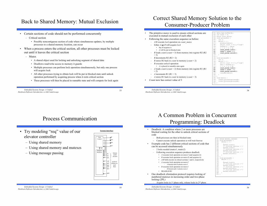
Back to Shared Memory: Mutual Exclusion
• Certain sections of code should not be performed concurrently
– Critical section
• Possibly noncontiguous section of code where simultaneous updates, by multiple
processes to a shared memory location, can occur
• When a process enters the critical section, all other processes must be locked
out until it leaves the critical section
– Mutex
• A shared object used for locking and unlocking segment of shared data
• Disallows read/write access to memory it guards
• Multiple processes can perform lock operation simultaneously, but only one process
will acquire lock
• All other processes trying to obtain lock will be put in blocked state until unlock
operation performed by acquiring process when it exits critical section
• These processes will then be placed in runnable state and will compete for lock again
34Embedded Systems Design: A Unified
Hardware/Software Introduction, (c) 2000 Vahid/Givargis
Correct Shared Memory Solution to the
Consumer-Producer Problem
• The primitive mutex is used to ensure critical sections areexecuted in mutual exclusion of each other
• Following the same execution sequence as before:
– A/B execute lock operation on count_mutex
– Either A or B will acquire lock
• Say B acquires it
• A will be put in blocked state
– B loads count (count = 3) from memory into register R2 (R2= 3)
– B decrements R2 (R2 = 2)
– B stores R2 back to count in memory (count = 2)
– B executes unlock operation
• A is placed in runnable state again
– A loads count (count = 2) from memory into register R1 (R1= 2)
– A increments R1 (R1 = 3)
– A stores R1 back to count in memory (count = 3)
• Count now has correct value of 3
01: data_type buffer[N];02: int count = 0;03: mutex count_mutex;04: void processA() {05: int i;06: while( 1 ) {07: produce(&data);08: while( count == N );/*loop*/09: buffer[i] = data;10: i = (i + 1) % N;11: count_mutex.lock();12: count = count + 1;13: count_mutex.unlock();14: }15: }16: void processB() {17: int i;18: while( 1 ) {19: while( count == 0 );/*loop*/20: data = buffer[i];21: i = (i + 1) % N;22: count_mutex.lock();23: count = count - 1;24: count_mutex.unlock();25: consume(&data);26: }27: }28: void main() {29: create_process(processA);30: create_process(processB);31: }
35Embedded Systems Design: A Unified
Hardware/Software Introduction, (c) 2000 Vahid/Givargis
Process Communication
• Try modeling “req” value of our
elevator controller
– Using shared memory
– Using shared memory and mutexes
– Using message passing buttons
inside
elevator
Unit
Control
b1
down
open
floor
...
Request
Resolver
...
up/down
buttons on
each
floor
b2
bN
up1
up2
dn2
dnN
req
up
System interface
up3
dn3
36Embedded Systems Design: A Unified
Hardware/Software Introduction, (c) 2000 Vahid/Givargis
A Common Problem in Concurrent
Programming: Deadlock
• Deadlock: A condition where 2 or more processes areblocked waiting for the other to unlock critical sections ofcode
– Both processes are then in blocked state
– Cannot execute unlock operation so will wait forever
• Example code has 2 different critical sections of code thatcan be accessed simultaneously
– 2 locks needed (mutex1, mutex2)
– Following execution sequence produces deadlock
• A executes lock operation on mutex1 (and acquires it)
• B executes lock operation on mutex2( and acquires it)
• A/B both execute in critical sections 1 and 2, respectively
• A executes lock operation on mutex2
– A blocked until B unlocks mutex2
• B executes lock operation on mutex1– B blocked until A unlocks mutex1
• DEADLOCK!
• One deadlock elimination protocol requires locking ofnumbered mutexes in increasing order and two-phaselocking (2PL)
– Acquire locks in 1st phase only, release locks in 2nd phase
01: mutex mutex1, mutex2;02: void processA() {03: while( 1 ) {04: …05: mutex1.lock();06: /* critical section 1 */07: mutex2.lock();08: /* critical section 2 */09: mutex2.unlock();10: /* critical section 1 */11: mutex1.unlock();12: }13: }14: void processB() {15: while( 1 ) {16: …17: mutex2.lock();18: /* critical section 2 */19: mutex1.lock();20: /* critical section 1 */21: mutex1.unlock();22: /* critical section 2 */23: mutex2.unlock();24: }25: }
37Embedded Systems Design: A Unified
Hardware/Software Introduction, (c) 2000 Vahid/Givargis
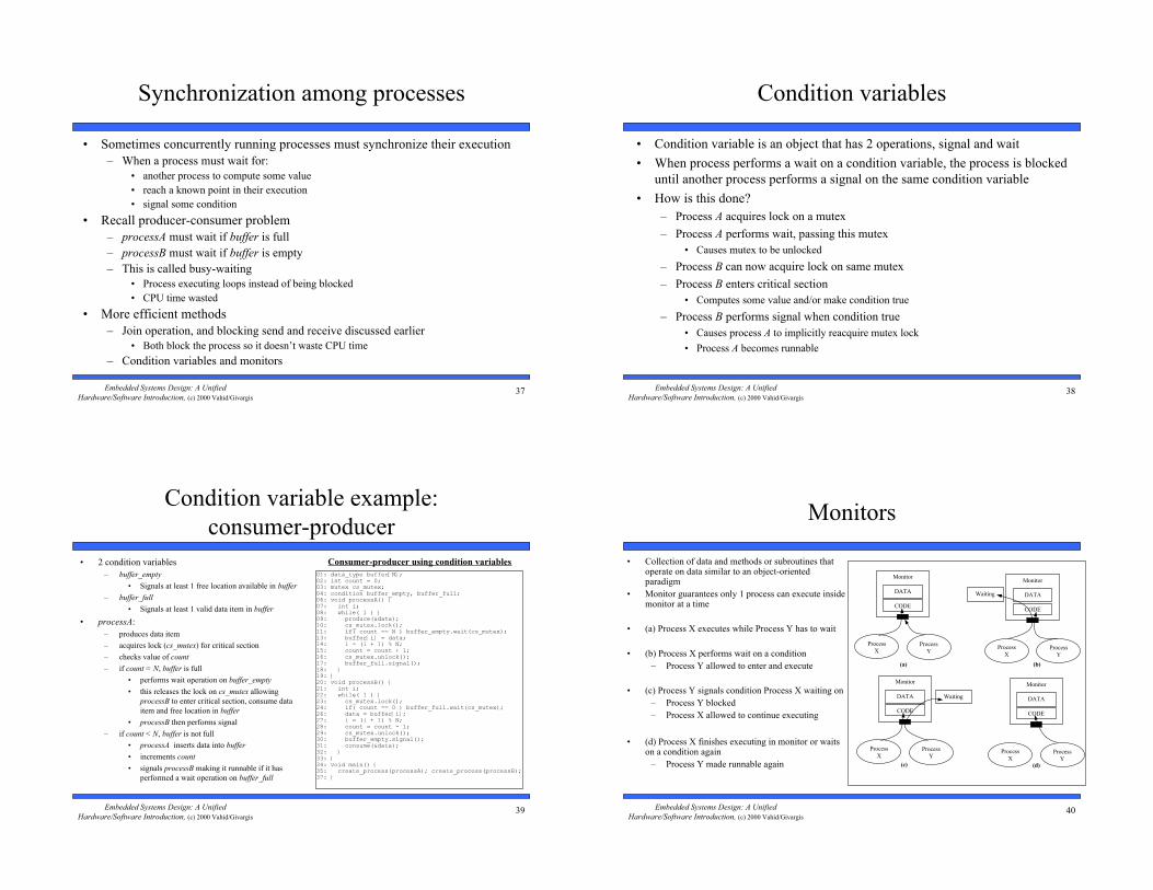
Synchronization among processes
• Sometimes concurrently running processes must synchronize their execution
– When a process must wait for:
• another process to compute some value
• reach a known point in their execution
• signal some condition
• Recall producer-consumer problem
– processA must wait if buffer is full
– processB must wait if buffer is empty
– This is called busy-waiting
• Process executing loops instead of being blocked
• CPU time wasted
• More efficient methods
– Join operation, and blocking send and receive discussed earlier
• Both block the process so it doesn’t waste CPU time
– Condition variables and monitors
38Embedded Systems Design: A Unified
Hardware/Software Introduction, (c) 2000 Vahid/Givargis
Condition variables
• Condition variable is an object that has 2 operations, signal and wait
• When process performs a wait on a condition variable, the process is blocked
until another process performs a signal on the same condition variable
• How is this done?
– Process A acquires lock on a mutex
– Process A performs wait, passing this mutex
• Causes mutex to be unlocked
– Process B can now acquire lock on same mutex
– Process B enters critical section
• Computes some value and/or make condition true
– Process B performs signal when condition true
• Causes process A to implicitly reacquire mutex lock
• Process A becomes runnable
39Embedded Systems Design: A Unified
Hardware/Software Introduction, (c) 2000 Vahid/Givargis
Condition variable example:
consumer-producer
• 2 condition variables
– buffer_empty
• Signals at least 1 free location available in buffer
– buffer_full
• Signals at least 1 valid data item in buffer
• processA:
– produces data item
– acquires lock (cs_mutex) for critical section
– checks value of count
– if count = N, buffer is full
• performs wait operation on buffer_empty
• this releases the lock on cs_mutex allowing
processB to enter critical section, consume data
item and free location in buffer
• processB then performs signal
– if count < N, buffer is not full
• processA inserts data into buffer
• increments count
• signals processB making it runnable if it has
performed a wait operation on buffer_full
01: data_type buffer[N];02: int count = 0;03: mutex cs_mutex;04: condition buffer_empty, buffer_full;06: void processA() {07: int i;08: while( 1 ) {09: produce(&data);10: cs_mutex.lock();11: if( count == N ) buffer_empty.wait(cs_mutex);13: buffer[i] = data;14: i = (i + 1) % N;15: count = count + 1;16: cs_mutex.unlock();17: buffer_full.signal();18: }19: }20: void processB() {21: int i;22: while( 1 ) {23: cs_mutex.lock();24: if( count == 0 ) buffer_full.wait(cs_mutex);26: data = buffer[i];27: i = (i + 1) % N;28: count = count - 1;29: cs_mutex.unlock();30: buffer_empty.signal();31: consume(&data);32: }33: }34: void main() {35: create_process(processA); create_process(processB);37: }
Consumer-producer using condition variables
40Embedded Systems Design: A Unified
Hardware/Software Introduction, (c) 2000 Vahid/Givargis
Monitors
• Collection of data and methods or subroutines thatoperate on data similar to an object-orientedparadigm
• Monitor guarantees only 1 process can execute insidemonitor at a time
• (a) Process X executes while Process Y has to wait
• (b) Process X performs wait on a condition
– Process Y allowed to enter and execute
• (c) Process Y signals condition Process X waiting on
– Process Y blocked
– Process X allowed to continue executing
• (d) Process X finishes executing in monitor or waitson a condition again
– Process Y made runnable again
Process
X
Monitor
DATA
CODE
(a)
Process
YProcess
X
Monitor
DATA
CODE
(b)
Process
Y
Process
X
Monitor
DATA
CODE
(c)
Process
YProcess
X
Monitor
DATA
CODE
(d)
Process
Y
Waiting
Waiting
41Embedded Systems Design: A Unified
Hardware/Software Introduction, (c) 2000 Vahid/Givargis
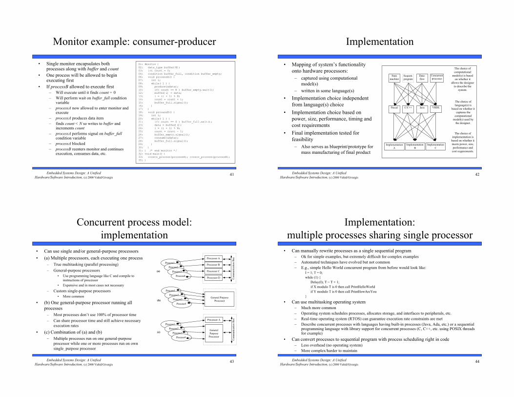
Monitor example: consumer-producer
• Single monitor encapsulates bothprocesses along with buffer and count
• One process will be allowed to beginexecuting first
• If processB allowed to execute first
– Will execute until it finds count = 0
– Will perform wait on buffer_full conditionvariable
– processA now allowed to enter monitor andexecute
– processA produces data item
– finds count < N so writes to buffer andincrements count
– processA performs signal on buffer_fullcondition variable
– processA blocked
– processB reenters monitor and continuesexecution, consumes data, etc.
01: Monitor {02: data_type buffer[N];03: int count = 0;04: condition buffer_full, condition buffer_empty;06: void processA() {07: int i;08: while( 1 ) {09: produce(&data);10: if( count == N ) buffer_empty.wait();12: buffer[i] = data;13: i = (i + 1) % N;14: count = count + 1;15: buffer_full.signal();16: }17: }18: void processB() {19: int i;20: while( 1 ) {21: if( count == 0 ) buffer_full.wait();23: data = buffer[i];24: i = (i + 1) % N;25: count = count - 1;26: buffer_empty.signal();27: consume(&data);28: buffer_full.signal();29: }30: }31: } /* end monitor */32: void main() {33: create_process(processA); create_process(processB);35: }
42Embedded Systems Design: A Unified
Hardware/Software Introduction, (c) 2000 Vahid/Givargis
Implementation
• Mapping of system’s functionality
onto hardware processors:
– captured using computational
model(s)
– written in some language(s)
• Implementation choice independent
from language(s) choice
• Implementation choice based on
power, size, performance, timing and
cost requirements
• Final implementation tested for
feasibility
– Also serves as blueprint/prototype for
mass manufacturing of final product
The choice of
computational
model(s) is based
on whether it
allows the designer
to describe the
system.
The choice of
language(s) is
based on whether it
captures the
computational
model(s) used by
the designer.
The choice of
implementation is
based on whether it
meets power, size,
performance and
cost requirements.
Sequent.
program
State
machine
Data-
flow
Concurrent
processes
C/C++Pascal Java VHDL
Implementation
A
Implementation
B
Implementation
C
43Embedded Systems Design: A Unified
Hardware/Software Introduction, (c) 2000 Vahid/Givargis
Concurrent process model:
implementation
• Can use single and/or general-purpose processors
• (a) Multiple processors, each executing one process
– True multitasking (parallel processing)
– General-purpose processors
• Use programming language like C and compile to
instructions of processor
• Expensive and in most cases not necessary
– Custom single-purpose processors
• More common
• (b) One general-purpose processor running all
processes
– Most processes don’t use 100% of processor time
– Can share processor time and still achieve necessary
execution rates
• (c) Combination of (a) and (b)
– Multiple processes run on one general-purpose
processor while one or more processes run on own
single_purpose processor
Process1
Process2
Process3
Process4
Processor A
Processor B
Processor C
Processor D Com
munic
atio
n B
us
(a)
(b)
Process1
Process2
Process3
Process4
General Purpose
Processor
Process1
Process2
Process3
Process4
Processor A
General
Purpose
Processor
Com
munic
atio
n B
us
(c)
44Embedded Systems Design: A Unified
Hardware/Software Introduction, (c) 2000 Vahid/Givargis
Implementation:
multiple processes sharing single processor
• Can manually rewrite processes as a single sequential program
– Ok for simple examples, but extremely difficult for complex examples
– Automated techniques have evolved but not common
– E.g., simple Hello World concurrent program from before would look like:
I = 1; T = 0;
while (1) {
Delay(I); T = T + 1;
if X modulo T is 0 then call PrintHelloWorld
if Y modulo T is 0 then call PrintHowAreYou
}
• Can use multitasking operating system
– Much more common
– Operating system schedules processes, allocates storage, and interfaces to peripherals, etc.
– Real-time operating system (RTOS) can guarantee execution rate constraints are met
– Describe concurrent processes with languages having built-in processes (Java, Ada, etc.) or a sequentialprogramming language with library support for concurrent processes (C, C++, etc. using POSIX threadsfor example)
• Can convert processes to sequential program with process scheduling right in code
– Less overhead (no operating system)
– More complex/harder to maintain
45Embedded Systems Design: A Unified
Hardware/Software Introduction, (c) 2000 Vahid/Givargis
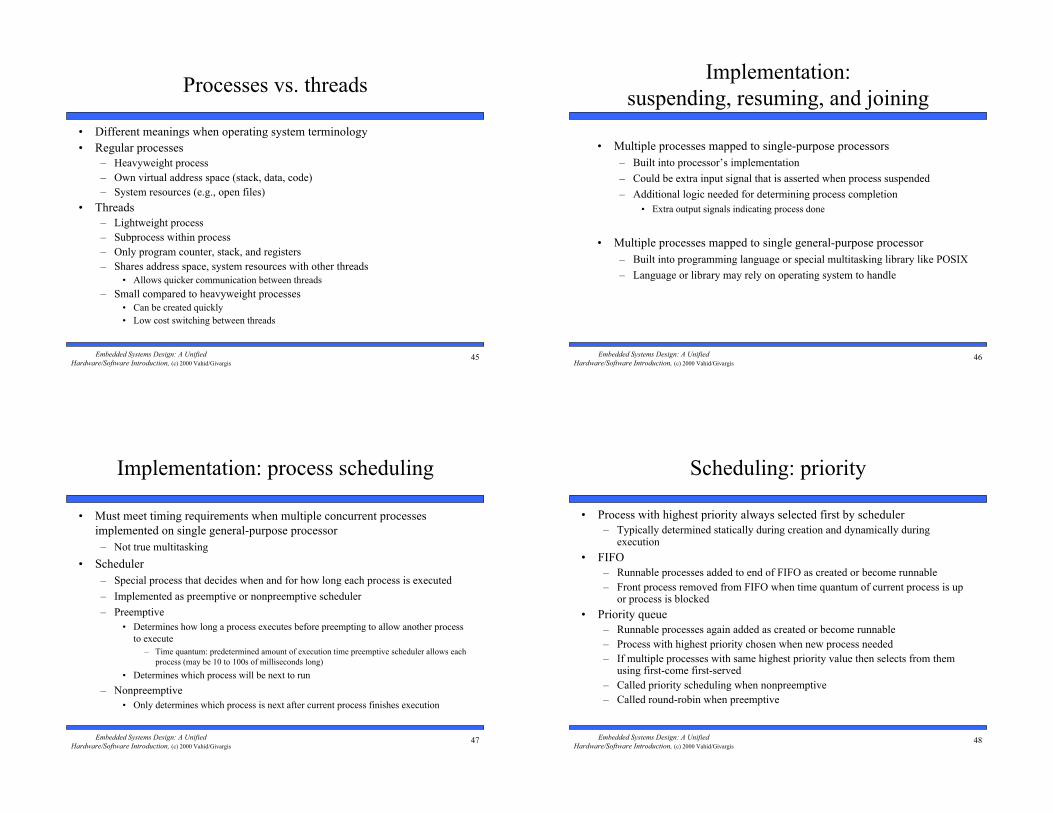
Processes vs. threads
• Different meanings when operating system terminology
• Regular processes
– Heavyweight process
– Own virtual address space (stack, data, code)
– System resources (e.g., open files)
• Threads
– Lightweight process
– Subprocess within process
– Only program counter, stack, and registers
– Shares address space, system resources with other threads
• Allows quicker communication between threads
– Small compared to heavyweight processes
• Can be created quickly
• Low cost switching between threads
46Embedded Systems Design: A Unified
Hardware/Software Introduction, (c) 2000 Vahid/Givargis
Implementation:
suspending, resuming, and joining
• Multiple processes mapped to single-purpose processors
– Built into processor’s implementation
– Could be extra input signal that is asserted when process suspended
– Additional logic needed for determining process completion
• Extra output signals indicating process done
• Multiple processes mapped to single general-purpose processor
– Built into programming language or special multitasking library like POSIX
– Language or library may rely on operating system to handle
47Embedded Systems Design: A Unified
Hardware/Software Introduction, (c) 2000 Vahid/Givargis
Implementation: process scheduling
• Must meet timing requirements when multiple concurrent processes
implemented on single general-purpose processor
– Not true multitasking
• Scheduler
– Special process that decides when and for how long each process is executed
– Implemented as preemptive or nonpreemptive scheduler
– Preemptive
• Determines how long a process executes before preempting to allow another process
to execute
– Time quantum: predetermined amount of execution time preemptive scheduler allows each
process (may be 10 to 100s of milliseconds long)
• Determines which process will be next to run
– Nonpreemptive
• Only determines which process is next after current process finishes execution
48Embedded Systems Design: A Unified
Hardware/Software Introduction, (c) 2000 Vahid/Givargis
Scheduling: priority
• Process with highest priority always selected first by scheduler
– Typically determined statically during creation and dynamically duringexecution
• FIFO
– Runnable processes added to end of FIFO as created or become runnable
– Front process removed from FIFO when time quantum of current process is upor process is blocked
• Priority queue
– Runnable processes again added as created or become runnable
– Process with highest priority chosen when new process needed
– If multiple processes with same highest priority value then selects from themusing first-come first-served
– Called priority scheduling when nonpreemptive
– Called round-robin when preemptive

49Embedded Systems Design: A Unified
Hardware/Software Introduction, (c) 2000 Vahid/Givargis
Priority assignment
• Period of process
– Repeating time interval the process must complete one execution within
• E.g., period = 100 ms
• Process must execute once every 100 ms
– Usually determined by the description of the system
• E.g., refresh rate of display is 27 times/sec
• Period = 37 ms
• Execution deadline
– Amount of time process must be completed by after it has started
• E.g., execution time = 5 ms, deadline = 20 ms, period = 100 ms
• Process must complete execution within 20 ms after it has begun regardless of its period
• Process begins at start of period, runs for 4 ms then is preempted
• Process suspended for 14 ms, then runs for the remaining 1 ms
• Completed within 4 + 14 + 1 = 19 ms which meets deadline of 20 ms
• Without deadline process could be suspended for much longer
• Rate monotonic scheduling
– Processes with shorter periods have higher priority
– Typically used when execution deadline = period
• Deadline monotonic scheduling
– Processes with shorter deadlines have higher priority
– Typically used when execution deadline < period
Process
A
B
C
D
E
F
Period
25 ms
50 ms
12 ms
100 ms
40 ms
75 ms
Priority
5
3
6
1
4
2
Process
G
H
I
J
K
L
Deadline
17 ms
50 ms
32 ms
10 ms
140 ms
32 ms
Priority
5
2
3
6
1
4
Rate monotonic
Deadline monotonic
50Embedded Systems Design: A Unified
Hardware/Software Introduction, (c) 2000 Vahid/Givargis
Real-time systems
• Systems composed of 2 or more cooperating, concurrent processes with
stringent execution time constraints
– E.g., set-top boxes have separate processes that read or decode video and/or
sound concurrently and must decode 20 frames/sec for output to appear
continuous
– Other examples with stringent time constraints are:
• digital cell phones
• navigation and process control systems
• assembly line monitoring systems
• multimedia and networking systems
• etc.
– Communication and synchronization between processes for these systems is
critical
– Therefore, concurrent process model best suited for describing these systems
51Embedded Systems Design: A Unified
Hardware/Software Introduction, (c) 2000 Vahid/Givargis
Real-time operating systems (RTOS)
• Provide mechanisms, primitives, and guidelines for building real-time embedded systems
• Windows CE
– Built specifically for embedded systems and appliance market
– Scalable real-time 32-bit platform
– Supports Windows API
– Perfect for systems designed to interface with Internet
– Preemptive priority scheduling with 256 priority levels per process
– Kernel is 400 Kbytes
• QNX
– Real-time microkernel surrounded by optional processes (resource managers) that provide POSIX and
UNIX compatibility
• Microkernels typically support only the most basic services
• Optional resource managers allow scalability from small ROM-based systems to huge multiprocessor systems
connected by various networking and communication technologies
– Preemptive process scheduling using FIFO, round-robin, adaptive, or priority-driven scheduling
– 32 priority levels per process
– Microkernel < 10 Kbytes and complies with POSIX real-time standard
52Embedded Systems Design: A Unified
Hardware/Software Introduction, (c) 2000 Vahid/Givargis
Summary
• Computation models are distinct from languages
• Sequential program model is popular
– Most common languages like C support it directly
• State machine models good for control
– Extensions like HCFSM provide additional power
– PSM combines state machines and sequential programs
• Concurrent process model for multi-task systems
– Communication and synchronization methods exist
– Scheduling is critical
• Dataflow model good for signal processing