Embed Size (px)
Citation preview
G H I E l e c t r o n i c s
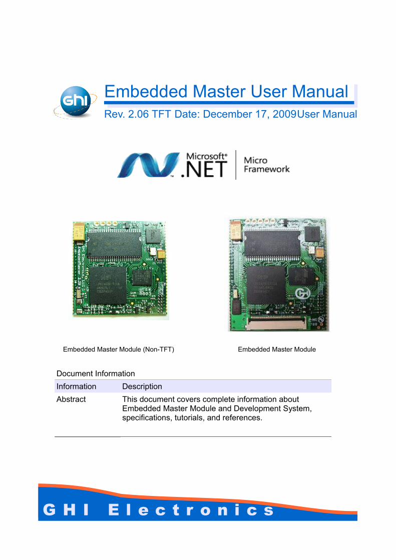
Embedded Master User ManualRev. 2.06 TFT Date: December 17, 2009User Manual
Embedded Master Module (Non-TFT) Embedded Master Module
Document InformationInformation DescriptionAbstract This document covers complete information about
Embedded Master Module and Development System, specifications, tutorials, and references.
GHI Electronics,LLC Embedded Master User Manual
Rev. 2.06 TFT Page 2 of 102 www.ghielectronics.com
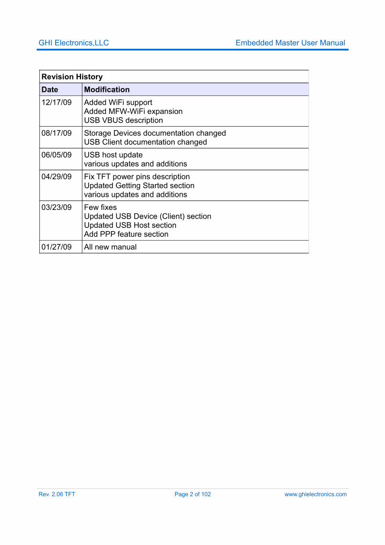
Revision HistoryDate Modification12/17/09 Added WiFi support
Added MFW-WiFi expansionUSB VBUS description
08/17/09 Storage Devices documentation changedUSB Client documentation changed
06/05/09 USB host updatevarious updates and additions
04/29/09 Fix TFT power pins descriptionUpdated Getting Started sectionvarious updates and additions
03/23/09 Few fixesUpdated USB Device (Client) sectionUpdated USB Host sectionAdd PPP feature section
01/27/09 All new manual
GHI Electronics,LLC Embedded Master User ManualTable of Contents
Table of Contents1.Introduction.....................................................................................4
1.1.What is The Microsoft .NET Micro Framework.....................41.2.What is Embedded Master Module.......................................51.3.What is CANxtra....................................................................61.4.What is USBizi......................................................................71.5.Example Applications............................................................81.6.Embedded Master Key Features..........................................9
2.Embedded Master Products.........................................................122.1.Embedded Master TFT Development System....................122.2.CANxtra In-Box Development System................................182.3.TFT Expansion and Touch Screen......................................182.4.Embedded Master VGA Expansion....................................202.5.Embedded Master Module Break-out board.......................202.6.Micro Framework WiFi Expansion......................................21
3.Embedded Master Architecture....................................................243.1.Block Diagram.....................................................................243.2.LPC2468/78 Microcontroller...............................................253.3.SDRAM...............................................................................253.4.FLASH.................................................................................253.5.GHI Extended Features......................................................25
4.Embedded Master design Consideration.....................................264.1.Hardware.............................................................................264.2.Software..............................................................................264.3.Embedded Master Placement.............................................26
5.Pin-Out Description......................................................................285.1.Buttons on Embedded Master Development System.........35
6.Getting Started with Embedded Master.......................................366.1.How Simple?.......................................................................366.2.All you need to start up.......................................................376.3.Powering up........................................................................386.4.USB Debugging Driver Setup.............................................386.5.Virtual COM Setup..............................................................396.6.Development System First Power-up.................................406.7.MFDeploy Tool....................................................................446.8.Embedded Master Library...................................................46
7.Developing with the Emulator.......................................................498.Updating Embedded Master Firmware.........................................51
8.1.Updating Firmware (TinyCLR) using MFDeploy.................518.2.Updating TinyBooter............................................................52
9.GHI Loader...................................................................................539.1.Entering GHI Loader User Interface...................................539.2.GHI Loader Commands......................................................54
10.Selecting the Debug Interface....................................................5711.Hardware and Software Library..................................................58
11.1.Graphics............................................................................5811.2.General Purpose I/O with External Interrupt.....................6011.3.SPI.....................................................................................6111.4.I2C.....................................................................................6311.5.UART.................................................................................6411.6.Hardware Piezo.................................................................6611.7.Analog Inputs/Outputs.......................................................6711.8.PWM..................................................................................6811.9.Processor Register Access...............................................6911.10.Ethernet and TCP/IP.......................................................6911.11.CAN.................................................................................7111.12.USB Device (Client)........................................................7211.13.Storage Devices (SD, USB) / FAT File System...............7511.14.USB Hosting and Peripherals.........................................7611.15.Miscellaneous Hardware Access....................................8711.16.System Information.........................................................8711.17.Power Control / Sleep.....................................................8811.18.PPP .................................................................................8911.19.In-Field Update................................................................9011.20.Managed Application Protection......................................9011.21.Wireless LAN WiFi (IEEE 802.11b).................................90
12.SideShow Support......................................................................9213.Custom Native Drivers................................................................93
13.1.Requesting New Native Driver..........................................9313.2.Required Native Drivers....................................................9313.3.Semi-Native Drivers..........................................................93
14.Supported Devices.....................................................................95Licensing........................................................................................102Disclaimer......................................................................................102
Rev. 2.06 TFT Page 3 of 102 www.ghielectronics.com
GHI Electronics,LLC Embedded Master User ManualIntroduction
1. Introduction
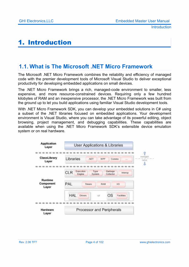
1.1. What is The Microsoft .NET Micro FrameworkThe Microsoft .NET Micro Framework combines the reliability and efficiency of managed code with the premier development tools of Microsoft Visual Studio to deliver exceptional productivity for developing embedded applications on small devices.The .NET Micro Framework brings a rich, managed-code environment to smaller, less expensive, and more resource-constrained devices. Requiring only a few hundred kilobytes of RAM and an inexpensive processor, the .NET Micro Framework was built from the ground up to let you build applications using familiar Visual Studio development tools.With .NET Micro Framework SDK, you can develop your embedded solutions in C# using a subset of the .NET libraries focused on embedded applications. Your development environment is Visual Studio, where you can take advantage of its powerful editing, object browsing, project management, and debugging capabilities. These capabilities are available when using the .NET Micro Framework SDK’s extensible device emulation system or on real hardware.
Rev. 2.06 TFT Page 4 of 102 www.ghielectronics.com
GHI Electronics,LLC Embedded Master User ManualIntroduction
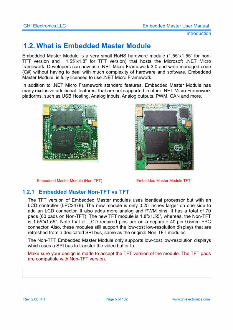
1.2. What is Embedded Master ModuleEmbedded Master Module is a very small RoHS hardware module (1.55”x1.55” for non-TFT version and 1.55”x1.8” for TFT version) that hosts the Microsoft .NET Micro framework. Developers can now use .NET Micro Framework 3.0 and write managed code (C#) without having to deal with much complexity of hardware and software. Embedded Master Module is fully licensed to use .NET Micro Framework.In addition to .NET Micro Framework standard features, Embedded Master Module has many exclusive additional features that are not supported in other .NET Micro Framework platforms, such as USB Hosting, Analog inputs, Analog outputs, PWM, CAN and more.
Embedded Master Module (Non-TFT) Embedded Master Module TFT
1.2.1 Embedded Master Non-TFT vs TFTThe TFT version of Embedded Master modules uses identical processor but with an LCD controller (LPC2478). The new module is only 0.25 inches larger on one side to add an LCD connector. It also adds more analog and PWM pins. It has a total of 70 pads (60 pads on Non-TFT). The new TFT module is 1.8”x1.55”, whereas, the Non-TFT is 1.55”x1.55”. Note that all LCD required pins are on a separate 40-pin 0.5mm FPC connector. Also, these modules still support the low-cost low-resolution displays that are refreshed from a dedicated SPI bus, same as the original Non-TFT modules.The Non-TFT Embedded Master Module only supports low-cost low-resolution displays which uses a SPI bus to transfer the video buffer to.Make sure your design is made to accept the TFT version of the module. The TFT pads are compatible with Non-TFT version.
Rev. 2.06 TFT Page 5 of 102 www.ghielectronics.com
GHI Electronics,LLC Embedded Master User ManualIntroduction
1.3. What is CANxtra
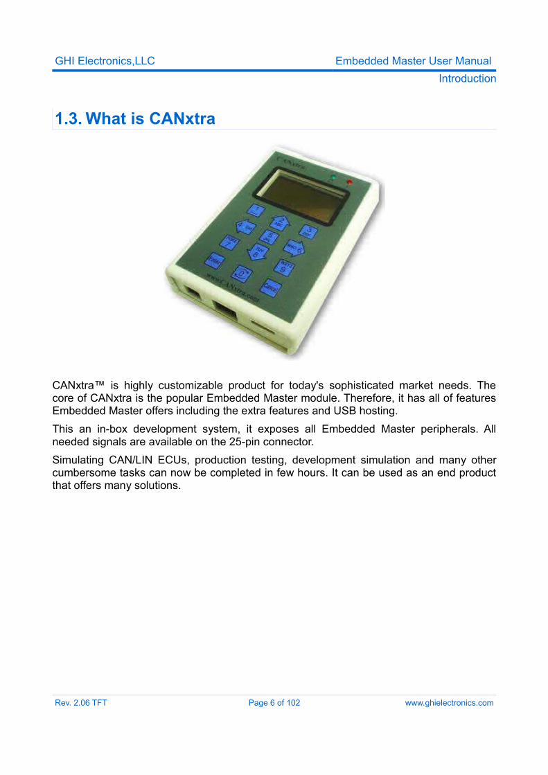
CANxtra™ is highly customizable product for today's sophisticated market needs. The core of CANxtra is the popular Embedded Master module. Therefore, it has all of features Embedded Master offers including the extra features and USB hosting.This an in-box development system, it exposes all Embedded Master peripherals. All needed signals are available on the 25-pin connector. Simulating CAN/LIN ECUs, production testing, development simulation and many other cumbersome tasks can now be completed in few hours. It can be used as an end product that offers many solutions.
Rev. 2.06 TFT Page 6 of 102 www.ghielectronics.com
GHI Electronics,LLC Embedded Master User ManualIntroduction
1.4. What is USBiziUSBizi chip -pronounced USB easy- is a headless .NET Micro Framework system based on LPC2388\LPC2387 chipsets. It is basically a subset of Embedded Master which provides many of the great features Embedded Master offers, with everything implemented on a single chip. This is the smallest and lowest cost Micro Framework device that still implements unique features like USB host.Its limitations include reduced Flash and RAM size than Embedded Master and no TCP/IP nor LCD/Graphics libraries are included. However, an LCD can be connected and controlled using some of the many GPIOs available or SPI.Comparison between Embedded Master and USBizi
Embedded Master USBiziRAM over 8000 KB 96 KB
FLASH over 4500 KB 512 KBUser RAM over 6000 KB 40 KBUser Flash over 3000 KB 100 KB
Native Graphics Yes NoNative Ethernet Yes No
GHI Library Yes Yes
USBizi chipset is available in two packages LQFP100 and LQFP144 . LQFP100 chipset is identical to the LQFP144 pin version except that it doesn't contain a USB host. USB device is still available and works exactly the same.
Rev. 2.06 TFT Page 7 of 102 www.ghielectronics.com
GHI Electronics,LLC Embedded Master User ManualIntroduction
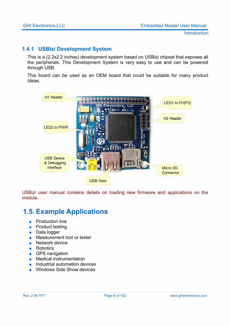
1.4.1 USBizi Development System This is a (2.2x2.2 inches) development system based on USBizi chipset that exposes all the peripherals. This Development System is very easy to use and can be powered through USB.This board can be used as an OEM board that could be suitable for many product Ideas.
USBizi user manual contains details on loading new firmware and applications on the module.
1.5. Example Applications● Production line● Product testing● Data logger● Measurement tool or tester● Network device● Robotics ● GPS navigation ● Medical instrumentation ● Industrial automation devices● Windows Side Show devices
Rev. 2.06 TFT Page 8 of 102 www.ghielectronics.com
H1 HeaderLED1 to H1(P3)
H2 Header
Micro SD Connector
USB Host
USB Device & Debugging
interface
LED2 to PWR
GHI Electronics,LLC Embedded Master User ManualIntroduction
1.6. Embedded Master Key Features
1.6.1 Software
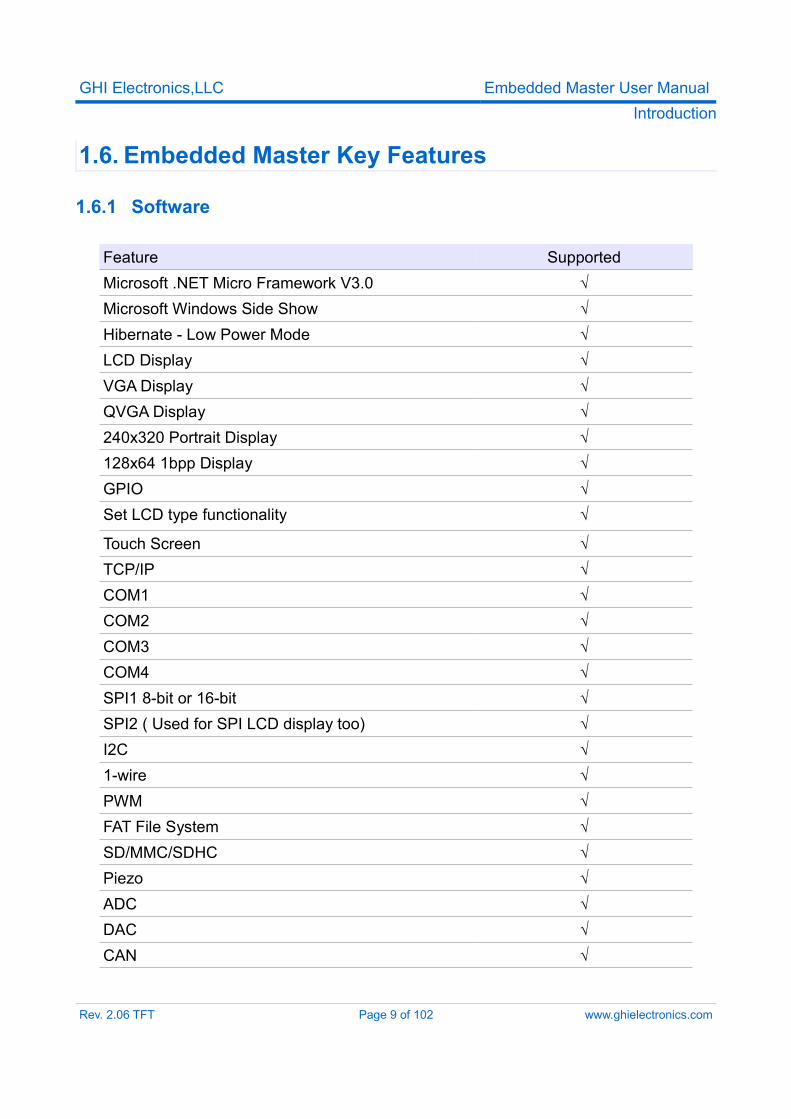
Feature SupportedMicrosoft .NET Micro Framework V3.0 √Microsoft Windows Side Show √Hibernate - Low Power Mode √LCD Display √VGA Display √QVGA Display √240x320 Portrait Display √128x64 1bpp Display √GPIO √Set LCD type functionality √
Touch Screen √TCP/IP √COM1 √COM2 √COM3 √COM4 √SPI1 8-bit or 16-bit √SPI2 ( Used for SPI LCD display too) √I2C √1-wire √PWM √FAT File System √SD/MMC/SDHC √Piezo √ADC √DAC √CAN √
Rev. 2.06 TFT Page 9 of 102 www.ghielectronics.com
GHI Electronics,LLC Embedded Master User ManualIntroduction
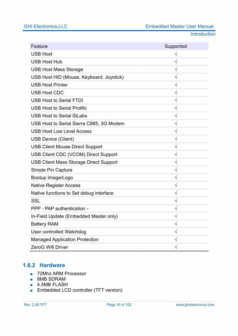
Feature SupportedUSB Host √USB Host Hub √USB Host Mass Storage √USB Host HID (Mouse, Keyboard, Joystick) √USB Host Printer √USB Host CDC √USB Host to Serial FTDI √USB Host to Serial Prolific √USB Host to Serial SiLabs √USB Host to Serial Sierra C885, 3G Modem √USB Host Low Level Access √USB Device (Client) √USB Client Mouse Direct Support √USB Client CDC (VCOM) Direct Support √USB Client Mass Storage Direct Support √Simple Pin Capture √Bootup Image/Logo √Native Register Access √Native functions to Set debug interface √SSL √PPP - PAP authentication - √In-Field Update (Embedded Master only) √Battery RAM √User controlled Watchdog √Managed Application Protection √ZeroG Wifi Driver √
1.6.2 Hardware● 72Mhz ARM Processor● 8MB SDRAM● 4.5MB FLASH● Embedded LCD controller (TFT version)
Rev. 2.06 TFT Page 10 of 102 www.ghielectronics.com
GHI Electronics,LLC Embedded Master User ManualIntroduction
● 10/100 Ethernet Interface● Embedded USB host/device● Graphics on SPI LCDs● 51 GPIO Pins + 20 on LCD Connector (45 on Non-TFT)● 31 Interrupt Inputs + 10 on LCD connector (30 on Non-TFT) ● 2 SPI (8/16bit) ● I2C● 4 UART● 2 CAN Channels● 7 10-bit Analog Inputs (4 on Non-TFT)● 10-bit Analog Output● 4-bit SD Memory card interface● 5 PWM with two separate clocks (2 on Non-TFT)● 160 mA current consumption with everything enabled● 40 mA Hibernate Mode● -40ºC to +85ºC Operational● RoHS Lead Free● Connector-less Mounting● Easy prototyping with even hand soldering
Rev. 2.06 TFT Page 11 of 102 www.ghielectronics.com
GHI Electronics,LLC Embedded Master User ManualEmbedded Master Products
2. Embedded Master Products
2.1. Embedded Master TFT Development System
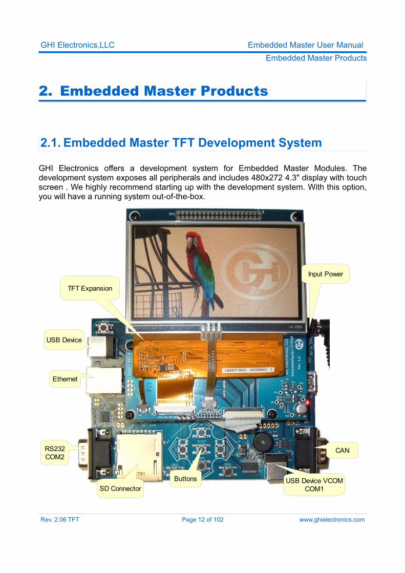
GHI Electronics offers a development system for Embedded Master Modules. The development system exposes all peripherals and includes 480x272 4.3" display with touch screen . We highly recommend starting up with the development system. With this option, you will have a running system out-of-the-box.
Rev. 2.06 TFT Page 12 of 102 www.ghielectronics.com
Input Power
CAN
USB Device VCOMCOM1SD Connector
RS232COM2
Ethernet
USB Device
Buttons
TFT Expansion
GHI Electronics,LLC Embedded Master User ManualEmbedded Master Products
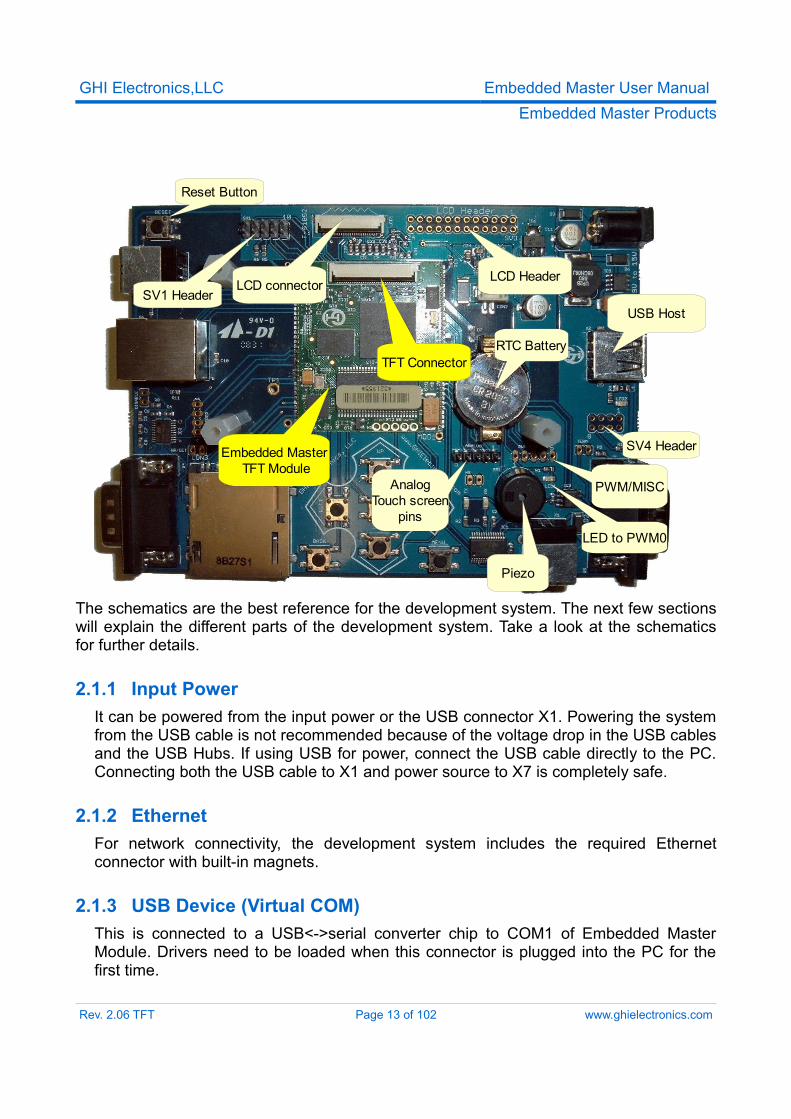
The schematics are the best reference for the development system. The next few sections will explain the different parts of the development system. Take a look at the schematics for further details.
2.1.1 Input PowerIt can be powered from the input power or the USB connector X1. Powering the system from the USB cable is not recommended because of the voltage drop in the USB cables and the USB Hubs. If using USB for power, connect the USB cable directly to the PC. Connecting both the USB cable to X1 and power source to X7 is completely safe.
2.1.2 EthernetFor network connectivity, the development system includes the required Ethernet connector with built-in magnets.
2.1.3 USB Device (Virtual COM)This is connected to a USB<->serial converter chip to COM1 of Embedded Master Module. Drivers need to be loaded when this connector is plugged into the PC for the first time.
Rev. 2.06 TFT Page 13 of 102 www.ghielectronics.com
USB Host
Piezo
RTC Battery
SV4 Header
SV1 Header
AnalogTouch screen
pins
PWM/MISC
Embedded Master TFT Module
LCD HeaderLCD connector
TFT Connector
LED to PWM0
Reset Button
GHI Electronics,LLC Embedded Master User ManualEmbedded Master Products
2.1.4 USB DeviceThis connector is connected to the internal USB device peripheral of Embedded Master Module. USB device feature allows Embedded Master to become almost any USB peripheral that can be connected to a PC. .NET Micro Framework 3.0 has the ability to change what type of USB device you need to create.
2.1.5 USB HostEmbedded Master Module's USB Host connector. This connector supplies 5V to the connected USB device through a 250mA resettable fuse. The LED next to the connector is an indicator if 5V power is available or not.
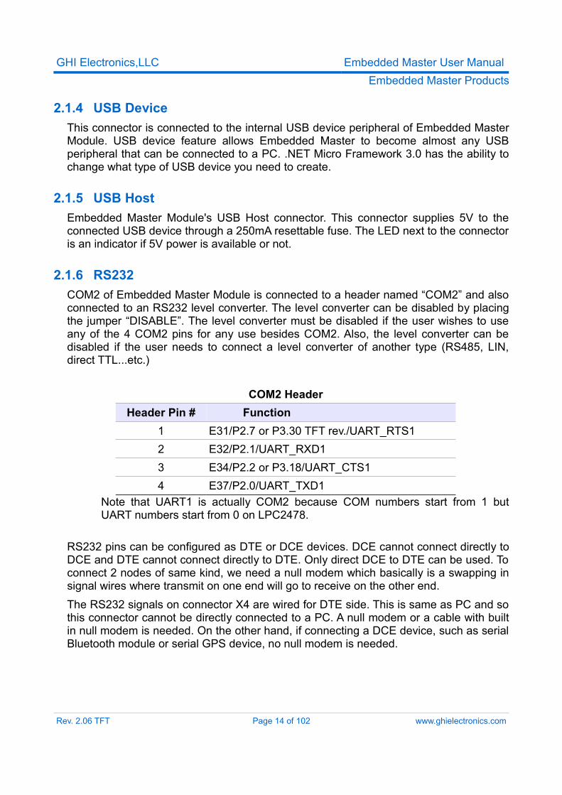
2.1.6 RS232COM2 of Embedded Master Module is connected to a header named “COM2” and also connected to an RS232 level converter. The level converter can be disabled by placing the jumper “DISABLE”. The level converter must be disabled if the user wishes to use any of the 4 COM2 pins for any use besides COM2. Also, the level converter can be disabled if the user needs to connect a level converter of another type (RS485, LIN, direct TTL...etc.)
COM2 HeaderHeader Pin # Function
1 E31/P2.7 or P3.30 TFT rev./UART_RTS12 E32/P2.1/UART_RXD13 E34/P2.2 or P3.18/UART_CTS14 E37/P2.0/UART_TXD1
Note that UART1 is actually COM2 because COM numbers start from 1 but UART numbers start from 0 on LPC2478.
RS232 pins can be configured as DTE or DCE devices. DCE cannot connect directly to DCE and DTE cannot connect directly to DTE. Only direct DCE to DTE can be used. To connect 2 nodes of same kind, we need a null modem which basically is a swapping in signal wires where transmit on one end will go to receive on the other end.The RS232 signals on connector X4 are wired for DTE side. This is same as PC and so this connector cannot be directly connected to a PC. A null modem or a cable with built in null modem is needed. On the other hand, if connecting a DCE device, such as serial Bluetooth module or serial GPS device, no null modem is needed.
Rev. 2.06 TFT Page 14 of 102 www.ghielectronics.com
GHI Electronics,LLC Embedded Master User ManualEmbedded Master Products
2.1.7 CANThe development system wires one of the available CAN channels (channel 1) to a high speed transceiver. The outputs CAN_High and CAN_Low are connected to pins 7 and 2 respectively on connector X5. Pins 3 and 6 are connected to ground.High speed CAN transceivers require termination on the very last endings of the twisted pair wires. 120 ohm resistor should be on every end. If the board is connected to a system with no termination, short the “TERM” jumper to enable on-board termination resistor.
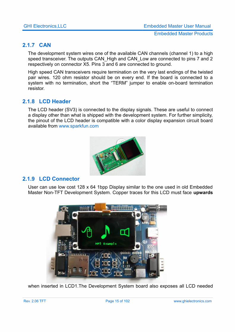
2.1.8 LCD HeaderThe LCD header (SV3) is connected to the display signals. These are useful to connect a display other than what is shipped with the development system. For further simplicity, the pinout of the LCD header is compatible with a color display expansion circuit board available from www.sparkfun.com
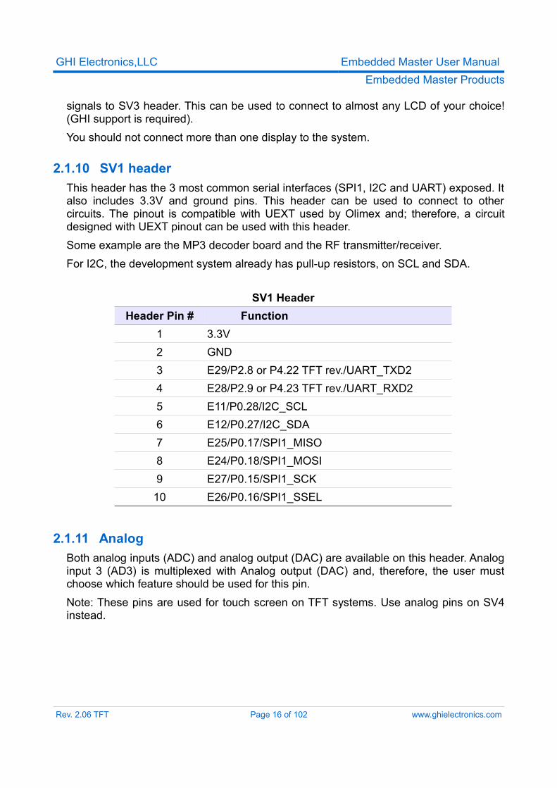
2.1.9 LCD ConnectorUser can use low cost 128 x 64 1bpp Display similar to the one used in old Embedded Master Non-TFT Development System. Copper traces for this LCD must face upwards
when inserted in LCD1.The Development System board also exposes all LCD needed
Rev. 2.06 TFT Page 15 of 102 www.ghielectronics.com
GHI Electronics,LLC Embedded Master User ManualEmbedded Master Products
signals to SV3 header. This can be used to connect to almost any LCD of your choice! (GHI support is required).You should not connect more than one display to the system.
2.1.10 SV1 headerThis header has the 3 most common serial interfaces (SPI1, I2C and UART) exposed. It also includes 3.3V and ground pins. This header can be used to connect to other circuits. The pinout is compatible with UEXT used by Olimex and; therefore, a circuit designed with UEXT pinout can be used with this header.Some example are the MP3 decoder board and the RF transmitter/receiver.For I2C, the development system already has pull-up resistors, on SCL and SDA.
SV1 HeaderHeader Pin # Function
1 3.3V2 GND3 E29/P2.8 or P4.22 TFT rev./UART_TXD24 E28/P2.9 or P4.23 TFT rev./UART_RXD25 E11/P0.28/I2C_SCL6 E12/P0.27/I2C_SDA7 E25/P0.17/SPI1_MISO8 E24/P0.18/SPI1_MOSI9 E27/P0.15/SPI1_SCK10 E26/P0.16/SPI1_SSEL
2.1.11 AnalogBoth analog inputs (ADC) and analog output (DAC) are available on this header. Analog input 3 (AD3) is multiplexed with Analog output (DAC) and, therefore, the user must choose which feature should be used for this pin.Note: These pins are used for touch screen on TFT systems. Use analog pins on SV4 instead.
Rev. 2.06 TFT Page 16 of 102 www.ghielectronics.com
GHI Electronics,LLC Embedded Master User ManualEmbedded Master Products
Analog HeaderHeader Pin # Function
1 E8/P0.23/ADC02 E7/P0.26/ADC3/AOUT3 E6/P0.25/ADC24 E5/P0.24/ADC1
2.1.12 PWM/MISCPWM and other miscellaneous pins are available on this header. An LED is connected to PWM0 for a quick test of the PWM functionality.
PWM/MISC HeaderHeader Pin # Function
1 E13/P3.16/PWM0 (PWM Timer 0)2 E14/P3.24/PWM1 (PWM Timer 1)3 E16/P1.19/USB_PWR_EN4 E19/P1.27/USB_OC#5 GND
2.1.13 SV4 headerThis header adds the extra pins introduced on the TFT version. They add 3 more analog inputs and 2 PWM outputs.
SV4 HeaderHeader Pin # Function
1 ET46/P0.13/AD72 ET45/P0.12/AD63 ET47/P1.31/AD54 ET49/P3.26/PWM3 (PWM Timer 1)5 TFT_PWR (3.3/2.5V)6 ET50/P3.17/PWM2 (PWM Timer 0)7 ET48/P3.27/PWM5 (PWM Timer 1)8 TFT_5V
Rev. 2.06 TFT Page 17 of 102 www.ghielectronics.com
GHI Electronics,LLC Embedded Master User ManualEmbedded Master Products
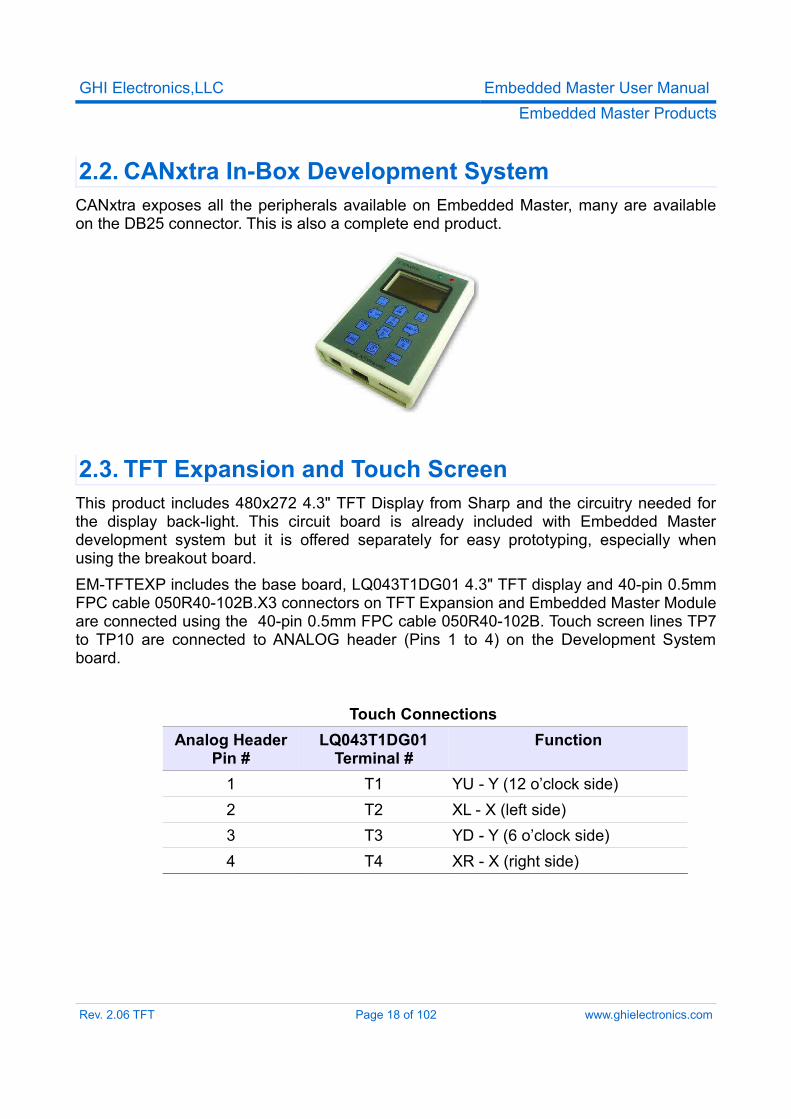
2.2. CANxtra In-Box Development SystemCANxtra exposes all the peripherals available on Embedded Master, many are available on the DB25 connector. This is also a complete end product.
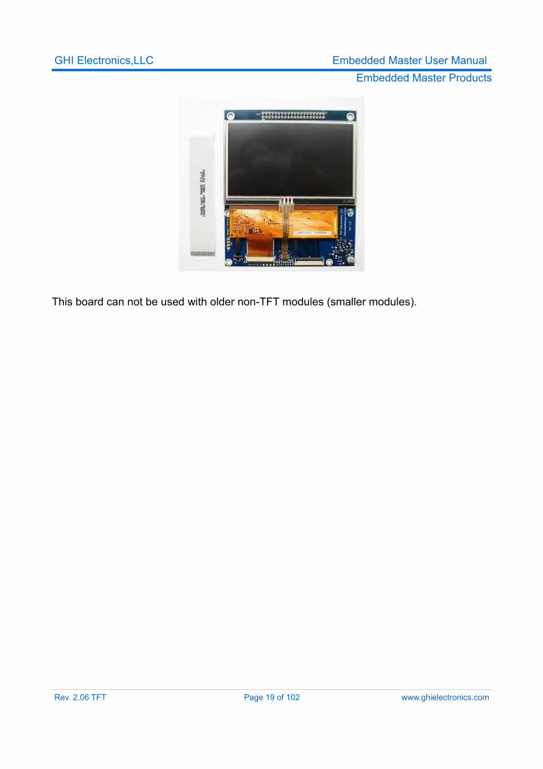
2.3. TFT Expansion and Touch ScreenThis product includes 480x272 4.3" TFT Display from Sharp and the circuitry needed for the display back-light. This circuit board is already included with Embedded Master development system but it is offered separately for easy prototyping, especially when using the breakout board.EM-TFTEXP includes the base board, LQ043T1DG01 4.3" TFT display and 40-pin 0.5mm FPC cable 050R40-102B.X3 connectors on TFT Expansion and Embedded Master Module are connected using the 40-pin 0.5mm FPC cable 050R40-102B. Touch screen lines TP7 to TP10 are connected to ANALOG header (Pins 1 to 4) on the Development System board.
Touch ConnectionsAnalog Header
Pin #LQ043T1DG01
Terminal #Function
1 T1 YU - Y (12 o’clock side)2 T2 XL - X (left side)3 T3 YD - Y (6 o’clock side)4 T4 XR - X (right side)
Rev. 2.06 TFT Page 18 of 102 www.ghielectronics.com
GHI Electronics,LLC Embedded Master User ManualEmbedded Master Products
This board can not be used with older non-TFT modules (smaller modules).
Rev. 2.06 TFT Page 19 of 102 www.ghielectronics.com
GHI Electronics,LLC Embedded Master User ManualEmbedded Master Products
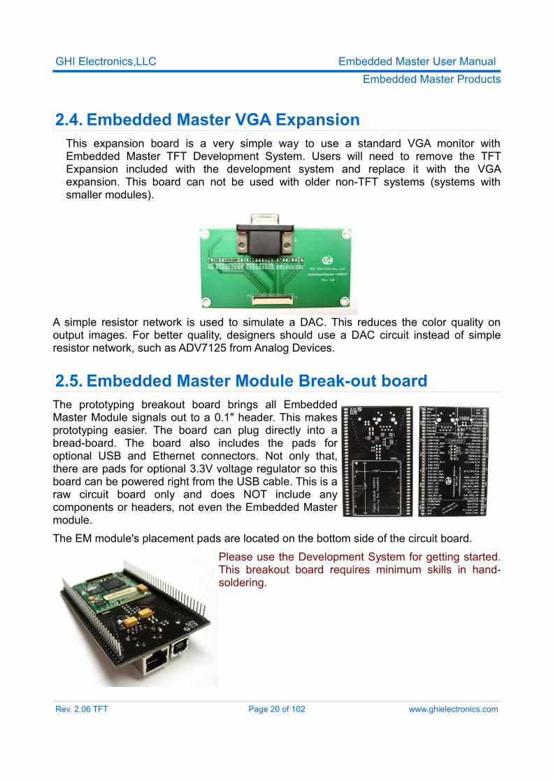
2.4. Embedded Master VGA ExpansionThis expansion board is a very simple way to use a standard VGA monitor with Embedded Master TFT Development System. Users will need to remove the TFT Expansion included with the development system and replace it with the VGA expansion. This board can not be used with older non-TFT systems (systems with smaller modules).
A simple resistor network is used to simulate a DAC. This reduces the color quality on output images. For better quality, designers should use a DAC circuit instead of simple resistor network, such as ADV7125 from Analog Devices.
2.5. Embedded Master Module Break-out boardThe prototyping breakout board brings all Embedded Master Module signals out to a 0.1" header. This makes prototyping easier. The board can plug directly into a bread-board. The board also includes the pads for optional USB and Ethernet connectors. Not only that, there are pads for optional 3.3V voltage regulator so this board can be powered right from the USB cable. This is a raw circuit board only and does NOT include any components or headers, not even the Embedded Master module. The EM module's placement pads are located on the bottom side of the circuit board.
Please use the Development System for getting started. This breakout board requires minimum skills in hand-soldering.
Rev. 2.06 TFT Page 20 of 102 www.ghielectronics.com
GHI Electronics,LLC Embedded Master User ManualEmbedded Master Products
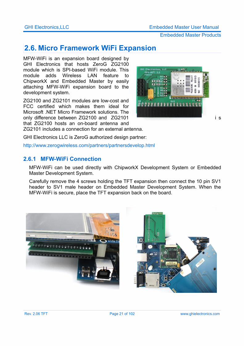
2.6. Micro Framework WiFi ExpansionMFW-WiFi is an expansion board designed by GHI Electronics that hosts ZeroG ZG2100 module which is SPI-based WiFi module. This module adds Wireless LAN feature to ChipworkX and Embedded Master by easily attaching MFW-WiFi expansion board to the development system.ZG2100 and ZG2101 modules are low-cost and FCC certified which makes them ideal for Microsoft .NET Micro Framework solutions. The only difference between ZG2100 and ZG2101 i s that ZG2100 hosts an on-board antenna and ZG2101 includes a connection for an external antenna.GHI Electronics LLC is ZeroG authorized design partner:http://www.zerogwireless.com/partners/partnersdevelop.html
2.6.1 MFW-WiFi ConnectionMFW-WiFi can be used directly with ChipworkX Development System or Embedded Master Development System.Carefully remove the 4 screws holding the TFT expansion then connect the 10 pin SV1 header to SV1 male header on Embedded Master Development System. When the MFW-WiFi is secure, place the TFT expansion back on the board.
Rev. 2.06 TFT Page 21 of 102 www.ghielectronics.com
GHI Electronics,LLC Embedded Master User ManualEmbedded Master Products
I/O used:1. E26: Reserved for MFW-WiFi external Interrupt. User should not use it.2. E28: Reserved for MFW-WiFi SPI SSEL signal. User should not use it.3. SPI1: Embedded Master accesses MFW-Wifi through this SPI interface. User can
only use the relative IOs (SCK, MOSI and MISO) for SPI interface.Note: In case hardware designer needs to support ZeroG WiFi module on different I/Os, it is possible to change the default IO through managed code. Consult ChipworkX library for further details.
2.6.2 Getting Started with WiFi Firmware1. Attach MFW-WiFi Expansion board to development system as described in the
previous section.2. Enable WiFi Interface (ZG2100) using ChipworkX.System.Net.Interface.Set()
method.3. Restart the system.4. Access TinyBooter and select Target->Configuration-> Network.
You will notice that Wireless Configurations are active.5. Assign static IP address, Subnet Mask and Default Gateway (and DNS Address if
needed) according to your wireless network.DHCP is also supported for this beta firmware.
6. Authentication: Ignore this field.7. Encryption:
TKIP: It is considered as No Encryption (No security).WEP: Fill in the key (64 bits, 10 hex digits) in the ReKey Internal field. (128 bits key is not supported in the current release)WPA: Fill in your Pass phrase.WPAPSK: Fill in precalculated PSK: 64 hex digits (32 bytes) in Network Key field.It is more recommended to use WPA option since it automatically calculates PSK code.You may use this tool as an example to calculate PSK:http://www.wireshark.org/tools/wpa-psk.html
8. Radio check boxes are ignored.9. Fill in the SSID field with ASCII HEX values.
For example:SSID string is GHI-AP
Rev. 2.06 TFT Page 22 of 102 www.ghielectronics.com
GHI Electronics,LLC Embedded Master User ManualEmbedded Master Products
SSID Field: 47 48 49 2d 41 50 00
Rev. 2.06 TFT Page 23 of 102 www.ghielectronics.com
GHI Electronics,LLC Embedded Master User ManualEmbedded Master Architecture
3. Embedded Master Architecture
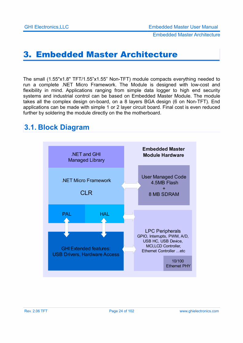
The small (1.55"x1.8" TFT/1.55”x1.55” Non-TFT) module compacts everything needed to run a complete .NET Micro Framework. The Module is designed with low-cost and flexibility in mind. Applications ranging from simple data logger to high end security systems and industrial control can be based on Embedded Master Module. The module takes all the complex design on-board, on a 8 layers BGA design (6 on Non-TFT). End applications can be made with simple 1 or 2 layer circuit board. Final cost is even reduced further by soldering the module directly on the the motherboard.
3.1. Block Diagram
Rev. 2.06 TFT Page 24 of 102 www.ghielectronics.com
LPC PeripheralsGPIO, Interrupts, PWM, A/D,
USB HC, USB Device, MCI,LCD Controller,
Ethernet Controller ...etcGHI Extended features:USB Drivers, Hardware Access
Embedded Master Module Hardware
.NET Micro Framework
CLR
HALPAL
User Managed Code 4.5MB Flash
+8 MB SDRAM
.NET and GHI Managed Library
10/100 Ethernet PHY
GHI Electronics,LLC Embedded Master User ManualEmbedded Master Architecture
3.2. LPC2468/78 MicrocontrollerThe LPC2468/78 72Mhz ARM7 32-bit processor is the core of Embedded Master Module. The LPC2468 contains a memory acceleration interface with 128-bit internal FLASH memory. This lets the processor core run with zero wait states. Comparing to executing code from 16-bit external FLASH we see over 10 times the execution speed. The internal FLASH is 0.5MB that is used to run the complete .NET Micro Framework core very efficiently. Also, the processor includes an RTC that can operate while while the processor is off. Embedded Master Module already has the needed circuitry to run the RTC. Users only need to add a battery or a super capacitor to VBAT pin.Further more, LPC2468 has a wide range of peripherals that adds a lot of functions and features to Embedded Master such as PWM, GPIO, LCD Controller, USB HC ...etc.While keeping all the great features. The TFT version also adds a built-in support to TFT displays.
3.3. SDRAM8MB of SDRAM come standard with Embedded Master Module. This is more than enough for applications using .NET Micro Framework and SideShow.
3.4. FLASH4MB of external flash is available on Embedded Master Modules. This doesn't include the 0.5MB internal flash used for Micro Framework CLR execution. External flash is used for system assemblies, boot loader, user deployment and EWR storage.about 1MB of the external FLASH is used for boot loader, system assemblies and other internal GHI resources. About 3MB is reserved for deployed managed applications, including resources. 256KB is reserved for EWR two regions, each region is 128KB and one of them is reserved for CLR use.EWR (Extended Week References) is a way for managed applications to store data on FLASH memory. Stored data have priorities, if more data needs to be stored and flash EWR region is full, some data of lower priority data will be overwritten. Consult .NET Micro Framework documentation for more details.If more storage is needed, SD memory cards and/or USB memory devices can be used. EWR do not work with removable media devices.
3.5. GHI Extended FeaturesEmbedded Master adds features to the .NET Micro Framework, such as embedded USB host stack, devices like mice , keyboards, joysticks, printers, Bluetooth dongles and more can be access from user's managed code. Other hardware classes are provided to support the many available peripherals such as ADC, DAC, PWM and more.
Rev. 2.06 TFT Page 25 of 102 www.ghielectronics.com
GHI Electronics,LLC Embedded Master User ManualEmbedded Master design Consideration
4. Embedded Master Design Consideration
4.1. HardwareThe following peripherals are recommended to be exposed from the module in any design, possibly hidden from the end user:
• UART0 (COM1) pins. (Updating TinyBooter/Firmware)• UP, Down and Select Buttons pins. (Selecting the BootLoader)• USB Device (Client) if it is used for debugging or TinyBooter communications
4.2. SoftwareEmbedded Master Module is usually shipped with GHI Bootloader and Tinybooter only. The firmware has to be downloaded through USB using Microsoft MFDeploy tool.If the user is using in-field firmware update feature (without USB), it would a good idea to have this USB port exposed in case of firmware update failure, for example a power loss.
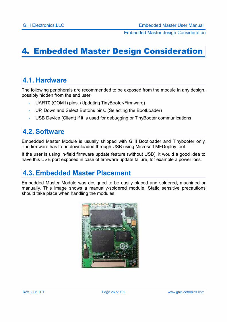
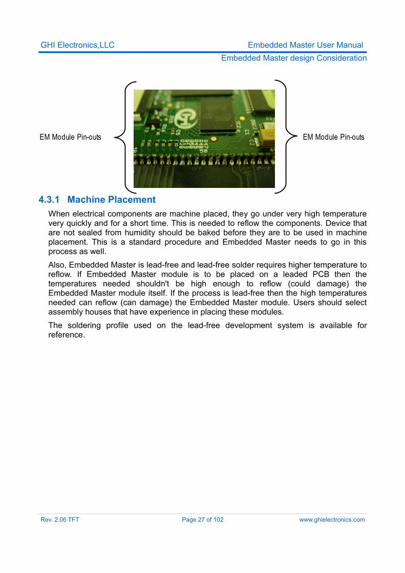
4.3. Embedded Master PlacementEmbedded Master Module was designed to be easily placed and soldered, machined or manually. This image shows a manually-soldered module. Static sensitive precautions should take place when handling the modules.
Rev. 2.06 TFT Page 26 of 102 www.ghielectronics.com
GHI Electronics,LLC Embedded Master User ManualEmbedded Master design Consideration
4.3.1 Machine PlacementWhen electrical components are machine placed, they go under very high temperature very quickly and for a short time. This is needed to reflow the components. Device that are not sealed from humidity should be baked before they are to be used in machine placement. This is a standard procedure and Embedded Master needs to go in this process as well.Also, Embedded Master is lead-free and lead-free solder requires higher temperature to reflow. If Embedded Master module is to be placed on a leaded PCB then the temperatures needed shouldn't be high enough to reflow (could damage) the Embedded Master module itself. If the process is lead-free then the high temperatures needed can reflow (can damage) the Embedded Master module. Users should select assembly houses that have experience in placing these modules.The soldering profile used on the lead-free development system is available for reference.
Rev. 2.06 TFT Page 27 of 102 www.ghielectronics.com
EM Module Pin-outs EM Module Pin-outs
GHI Electronics,LLC Embedded Master User ManualPin-Out Description
5. Pin-Out Description
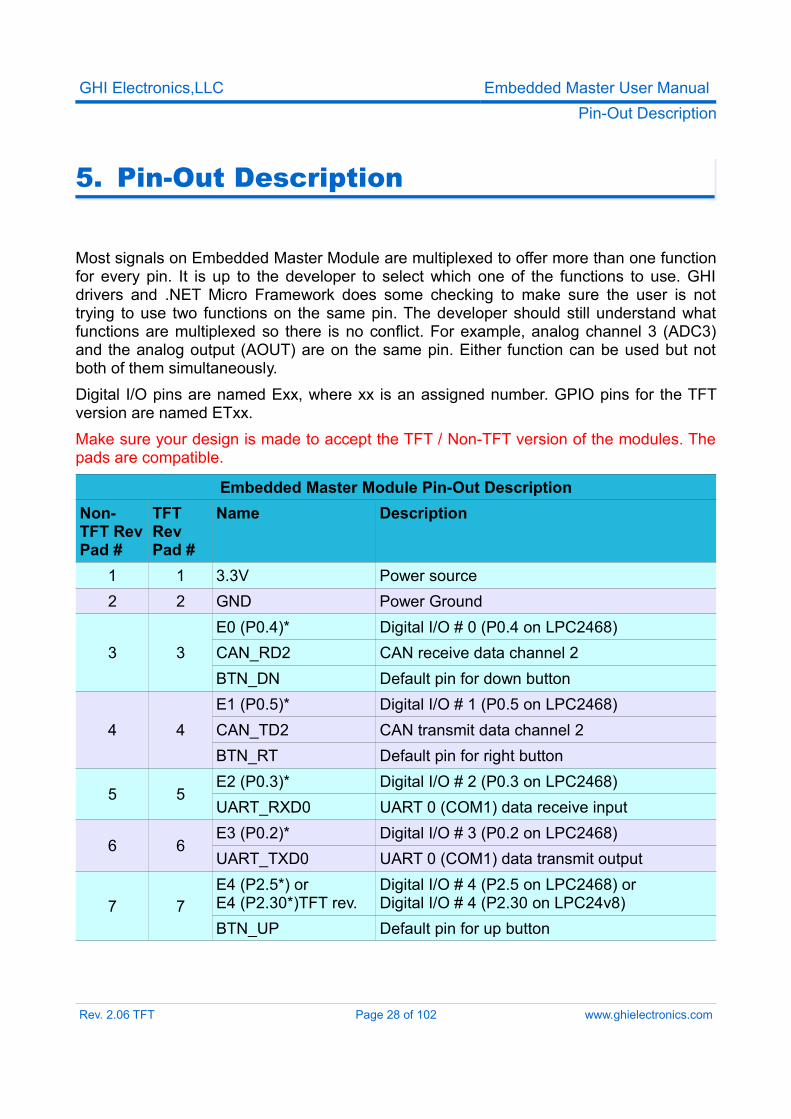
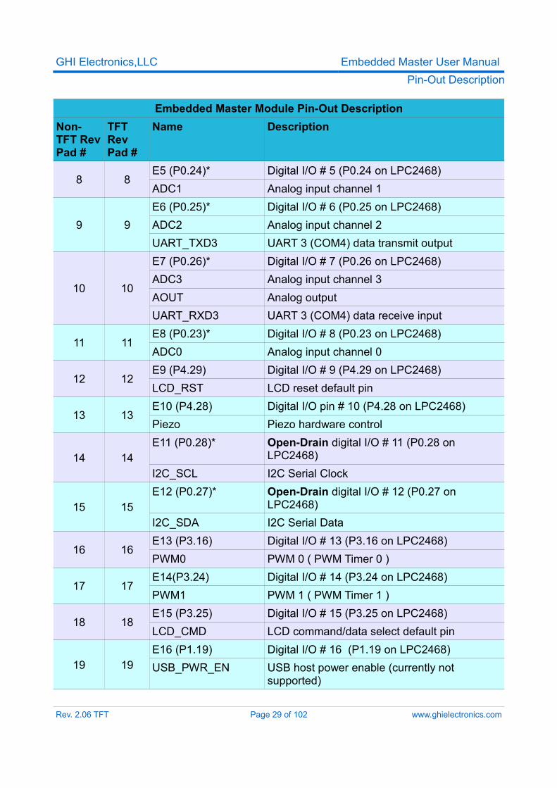
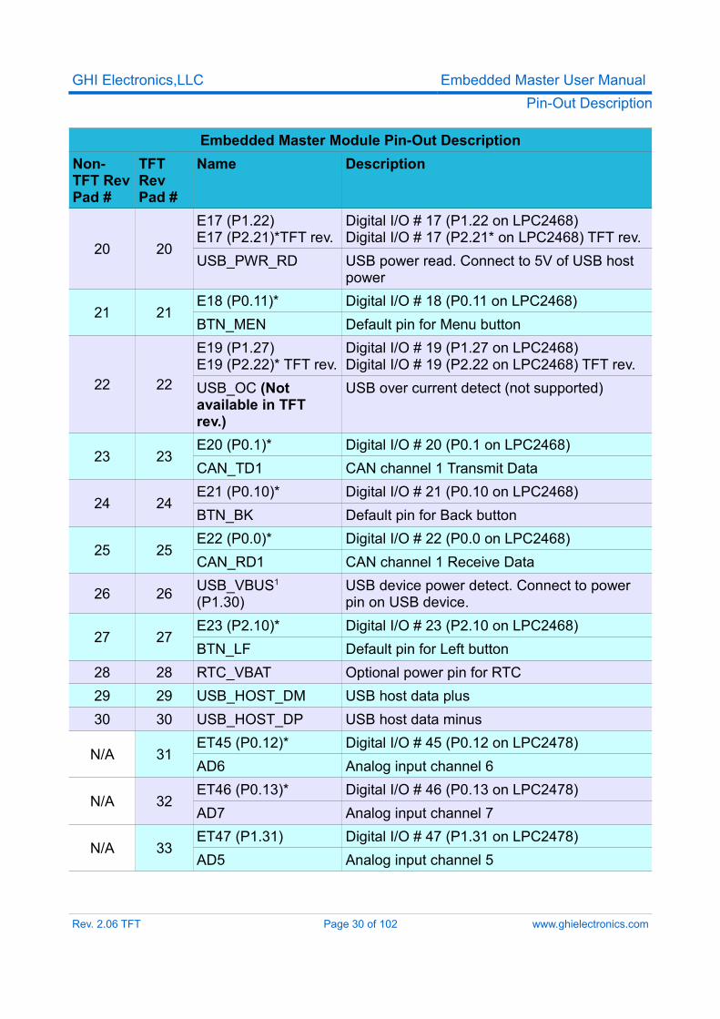
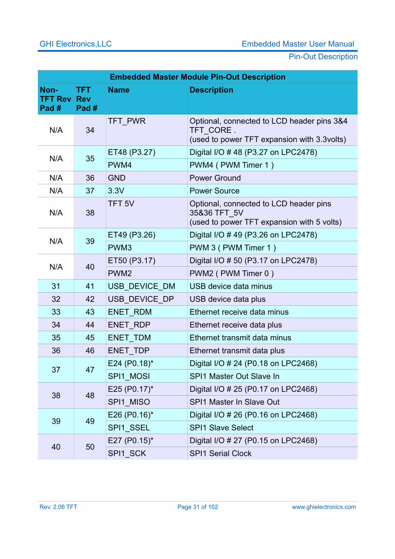
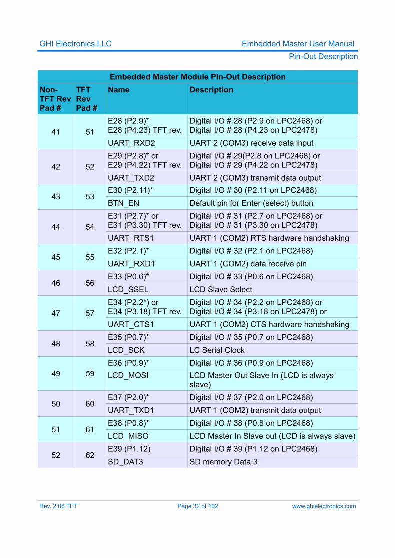
Most signals on Embedded Master Module are multiplexed to offer more than one function for every pin. It is up to the developer to select which one of the functions to use. GHI drivers and .NET Micro Framework does some checking to make sure the user is not trying to use two functions on the same pin. The developer should still understand what functions are multiplexed so there is no conflict. For example, analog channel 3 (ADC3) and the analog output (AOUT) are on the same pin. Either function can be used but not both of them simultaneously.Digital I/O pins are named Exx, where xx is an assigned number. GPIO pins for the TFT version are named ETxx.Make sure your design is made to accept the TFT / Non-TFT version of the modules. The pads are compatible.
Embedded Master Module Pin-Out DescriptionNon-TFT Rev Pad #
TFT RevPad #
Name Description
1 1 3.3V Power source2 2 GND Power Ground
3 3E0 (P0.4)* Digital I/O # 0 (P0.4 on LPC2468)CAN_RD2 CAN receive data channel 2BTN_DN Default pin for down button
4 4E1 (P0.5)* Digital I/O # 1 (P0.5 on LPC2468)CAN_TD2 CAN transmit data channel 2BTN_RT Default pin for right button
5 5E2 (P0.3)* Digital I/O # 2 (P0.3 on LPC2468)UART_RXD0 UART 0 (COM1) data receive input
6 6E3 (P0.2)* Digital I/O # 3 (P0.2 on LPC2468)UART_TXD0 UART 0 (COM1) data transmit output
7 7E4 (P2.5*) or E4 (P2.30*)TFT rev.
Digital I/O # 4 (P2.5 on LPC2468) or Digital I/O # 4 (P2.30 on LPC24v8)
BTN_UP Default pin for up button
Rev. 2.06 TFT Page 28 of 102 www.ghielectronics.com
GHI Electronics,LLC Embedded Master User ManualPin-Out Description
Embedded Master Module Pin-Out DescriptionNon-TFT Rev Pad #
TFT RevPad #
Name Description
8 8E5 (P0.24)* Digital I/O # 5 (P0.24 on LPC2468)ADC1 Analog input channel 1
9 9E6 (P0.25)* Digital I/O # 6 (P0.25 on LPC2468)ADC2 Analog input channel 2UART_TXD3 UART 3 (COM4) data transmit output
10 10
E7 (P0.26)* Digital I/O # 7 (P0.26 on LPC2468)ADC3 Analog input channel 3AOUT Analog outputUART_RXD3 UART 3 (COM4) data receive input
11 11E8 (P0.23)* Digital I/O # 8 (P0.23 on LPC2468)ADC0 Analog input channel 0
12 12E9 (P4.29) Digital I/O # 9 (P4.29 on LPC2468)LCD_RST LCD reset default pin
13 13E10 (P4.28) Digital I/O pin # 10 (P4.28 on LPC2468)Piezo Piezo hardware control
14 14E11 (P0.28)* Open-Drain digital I/O # 11 (P0.28 on
LPC2468)I2C_SCL I2C Serial Clock
15 15E12 (P0.27)* Open-Drain digital I/O # 12 (P0.27 on
LPC2468)I2C_SDA I2C Serial Data
16 16E13 (P3.16) Digital I/O # 13 (P3.16 on LPC2468)PWM0 PWM 0 ( PWM Timer 0 )
17 17E14(P3.24) Digital I/O # 14 (P3.24 on LPC2468)PWM1 PWM 1 ( PWM Timer 1 )
18 18E15 (P3.25) Digital I/O # 15 (P3.25 on LPC2468)LCD_CMD LCD command/data select default pin
19 19E16 (P1.19) Digital I/O # 16 (P1.19 on LPC2468)USB_PWR_EN USB host power enable (currently not
supported)
Rev. 2.06 TFT Page 29 of 102 www.ghielectronics.com
GHI Electronics,LLC Embedded Master User ManualPin-Out Description
Embedded Master Module Pin-Out DescriptionNon-TFT Rev Pad #
TFT RevPad #
Name Description
20 20
E17 (P1.22)E17 (P2.21)*TFT rev.
Digital I/O # 17 (P1.22 on LPC2468)Digital I/O # 17 (P2.21* on LPC2468) TFT rev.
USB_PWR_RD USB power read. Connect to 5V of USB host power
21 21E18 (P0.11)* Digital I/O # 18 (P0.11 on LPC2468)BTN_MEN Default pin for Menu button
22 22
E19 (P1.27)E19 (P2.22)* TFT rev.
Digital I/O # 19 (P1.27 on LPC2468)Digital I/O # 19 (P2.22 on LPC2468) TFT rev.
USB_OC (Not available in TFT rev.)
USB over current detect (not supported)
23 23E20 (P0.1)* Digital I/O # 20 (P0.1 on LPC2468)CAN_TD1 CAN channel 1 Transmit Data
24 24E21 (P0.10)* Digital I/O # 21 (P0.10 on LPC2468)BTN_BK Default pin for Back button
25 25E22 (P0.0)* Digital I/O # 22 (P0.0 on LPC2468)CAN_RD1 CAN channel 1 Receive Data
26 26 USB_VBUS1
(P1.30)USB device power detect. Connect to power pin on USB device.
27 27E23 (P2.10)* Digital I/O # 23 (P2.10 on LPC2468)BTN_LF Default pin for Left button
28 28 RTC_VBAT Optional power pin for RTC29 29 USB_HOST_DM USB host data plus30 30 USB_HOST_DP USB host data minus
N/A 31ET45 (P0.12)* Digital I/O # 45 (P0.12 on LPC2478)AD6 Analog input channel 6
N/A 32ET46 (P0.13)* Digital I/O # 46 (P0.13 on LPC2478)AD7 Analog input channel 7
N/A 33ET47 (P1.31) Digital I/O # 47 (P1.31 on LPC2478)AD5 Analog input channel 5
Rev. 2.06 TFT Page 30 of 102 www.ghielectronics.com
GHI Electronics,LLC Embedded Master User ManualPin-Out Description
Embedded Master Module Pin-Out DescriptionNon-TFT Rev Pad #
TFT RevPad #
Name Description
N/A 34TFT_PWR Optional, connected to LCD header pins 3&4
TFT_CORE .(used to power TFT expansion with 3.3volts)
N/A 35ET48 (P3.27)PWM4
Digital I/O # 48 (P3.27 on LPC2478)PWM4 ( PWM Timer 1 )
N/A 36 GND Power GroundN/A 37 3.3V Power Source
N/A 38TFT 5V Optional, connected to LCD header pins
35&36 TFT_5V(used to power TFT expansion with 5 volts)
N/A 39ET49 (P3.26)PWM3
Digital I/O # 49 (P3.26 on LPC2478)PWM 3 ( PWM Timer 1 )
N/A 40ET50 (P3.17)PWM2
Digital I/O # 50 (P3.17 on LPC2478)PWM2 ( PWM Timer 0 )
31 41 USB_DEVICE_DM USB device data minus32 42 USB_DEVICE_DP USB device data plus33 43 ENET_RDM Ethernet receive data minus34 44 ENET_RDP Ethernet receive data plus35 45 ENET_TDM Ethernet transmit data minus36 46 ENET_TDP Ethernet transmit data plus
37 47E24 (P0.18)* Digital I/O # 24 (P0.18 on LPC2468)SPI1_MOSI SPI1 Master Out Slave In
38 48E25 (P0.17)* Digital I/O # 25 (P0.17 on LPC2468)SPI1_MISO SPI1 Master In Slave Out
39 49E26 (P0.16)* Digital I/O # 26 (P0.16 on LPC2468)SPI1_SSEL SPI1 Slave Select
40 50E27 (P0.15)* Digital I/O # 27 (P0.15 on LPC2468)SPI1_SCK SPI1 Serial Clock
Rev. 2.06 TFT Page 31 of 102 www.ghielectronics.com
GHI Electronics,LLC Embedded Master User ManualPin-Out Description
Embedded Master Module Pin-Out DescriptionNon-TFT Rev Pad #
TFT RevPad #
Name Description
41 51E28 (P2.9)*E28 (P4.23) TFT rev.
Digital I/O # 28 (P2.9 on LPC2468) orDigital I/O # 28 (P4.23 on LPC2478)
UART_RXD2 UART 2 (COM3) receive data input
42 52E29 (P2.8)* orE29 (P4.22) TFT rev.
Digital I/O # 29(P2.8 on LPC2468) orDigital I/O # 29 (P4.22 on LPC2478)
UART_TXD2 UART 2 (COM3) transmit data output
43 53E30 (P2.11)* Digital I/O # 30 (P2.11 on LPC2468)BTN_EN Default pin for Enter (select) button
44 54E31 (P2.7)* orE31 (P3.30) TFT rev.
Digital I/O # 31 (P2.7 on LPC2468) orDigital I/O # 31 (P3.30 on LPC2478)
UART_RTS1 UART 1 (COM2) RTS hardware handshaking
45 55E32 (P2.1)* Digital I/O # 32 (P2.1 on LPC2468)UART_RXD1 UART 1 (COM2) data receive pin
46 56E33 (P0.6)* Digital I/O # 33 (P0.6 on LPC2468)LCD_SSEL LCD Slave Select
47 57E34 (P2.2*) or E34 (P3.18) TFT rev.
Digital I/O # 34 (P2.2 on LPC2468) or Digital I/O # 34 (P3.18 on LPC2478) or
UART_CTS1 UART 1 (COM2) CTS hardware handshaking
48 58E35 (P0.7)* Digital I/O # 35 (P0.7 on LPC2468)LCD_SCK LC Serial Clock
49 59E36 (P0.9)* Digital I/O # 36 (P0.9 on LPC2468)LCD_MOSI LCD Master Out Slave In (LCD is always
slave)
50 60E37 (P2.0)* Digital I/O # 37 (P2.0 on LPC2468)UART_TXD1 UART 1 (COM2) transmit data output
51 61E38 (P0.8)* Digital I/O # 38 (P0.8 on LPC2468)LCD_MISO LCD Master In Slave out (LCD is always slave)
52 62E39 (P1.12) Digital I/O # 39 (P1.12 on LPC2468)SD_DAT3 SD memory Data 3
Rev. 2.06 TFT Page 32 of 102 www.ghielectronics.com
GHI Electronics,LLC Embedded Master User ManualPin-Out Description
Embedded Master Module Pin-Out DescriptionNon-TFT Rev Pad #
TFT RevPad #
Name Description
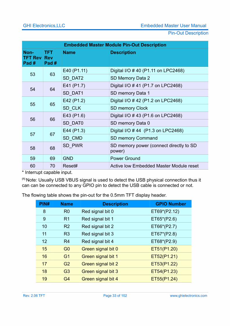
53 63E40 (P1.11) Digital I/O # 40 (P1.11 on LPC2468)SD_DAT2 SD Memory Data 2
54 64E41 (P1.7) Digital I/O # 41 (P1.7 on LPC2468)SD_DAT1 SD memory Data 1
55 65E42 (P1.2) Digital I/O # 42 (P1.2 on LPC2468)SD_CLK SD memory Clock
56 66E43 (P1.6) Digital I/O # 43 (P1.6 on LPC2468)SD_DAT0 SD memory Data 0
57 67E44 (P1.3) Digital I/O # 44 (P1.3 on LPC2468)SD_CMD SD memory Command
58 68 SD_PWR SD memory power (connect directly to SD power)
59 69 GND Power Ground60 70 Reset# Active low Embedded Master Module reset
* Interrupt capable input.(1) Note: Usually USB VBUS signal is used to detect the USB physical connection thus it can can be connected to any GPIO pin to detect the USB cable is connected or not.
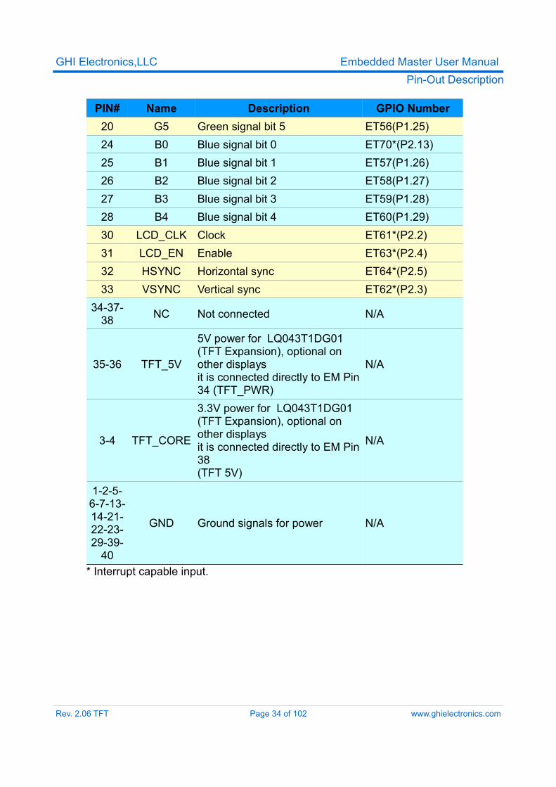
The flowing table shows the pin-out for the 0.5mm TFT display header.
PIN# Name Description GPIO Number8 R0 Red signal bit 0 ET69*(P2.12)9 R1 Red signal bit 1 ET65*(P2.6)10 R2 Red signal bit 2 ET66*(P2.7)11 R3 Red signal bit 3 ET67*(P2.8)12 R4 Red signal bit 4 ET68*(P2.9)15 G0 Green signal bit 0 ET51(P1.20)16 G1 Green signal bit 1 ET52(P1.21)17 G2 Green signal bit 2 ET53(P1.22)18 G3 Green signal bit 3 ET54(P1.23)19 G4 Green signal bit 4 ET55(P1.24)
Rev. 2.06 TFT Page 33 of 102 www.ghielectronics.com
GHI Electronics,LLC Embedded Master User ManualPin-Out Description
PIN# Name Description GPIO Number20 G5 Green signal bit 5 ET56(P1.25)24 B0 Blue signal bit 0 ET70*(P2.13)25 B1 Blue signal bit 1 ET57(P1.26)26 B2 Blue signal bit 2 ET58(P1.27)27 B3 Blue signal bit 3 ET59(P1.28)28 B4 Blue signal bit 4 ET60(P1.29)30 LCD_CLK Clock ET61*(P2.2)31 LCD_EN Enable ET63*(P2.4)32 HSYNC Horizontal sync ET64*(P2.5)33 VSYNC Vertical sync ET62*(P2.3)
34-37-38 NC Not connected N/A
35-36 TFT_5V
5V power for LQ043T1DG01 (TFT Expansion), optional on other displaysit is connected directly to EM Pin 34 (TFT_PWR)
N/A
3-4 TFT_CORE
3.3V power for LQ043T1DG01 (TFT Expansion), optional on other displaysit is connected directly to EM Pin 38 (TFT 5V)
N/A
1-2-5-6-7-13-14-21-22-23-29-39-
40
GND Ground signals for power N/A
* Interrupt capable input.
Rev. 2.06 TFT Page 34 of 102 www.ghielectronics.com
GHI Electronics,LLC Embedded Master User ManualPin-Out Description
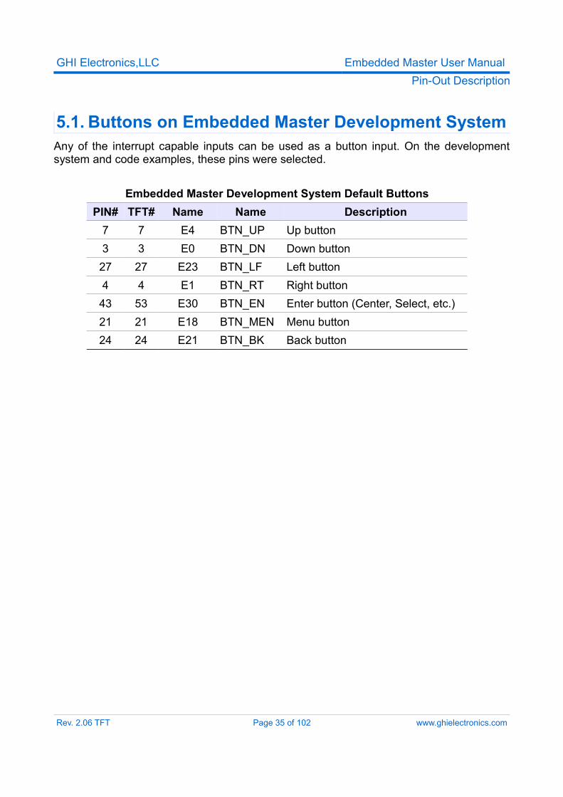
5.1. Buttons on Embedded Master Development SystemAny of the interrupt capable inputs can be used as a button input. On the development system and code examples, these pins were selected.
Embedded Master Development System Default ButtonsPIN# TFT# Name Name Description
7 7 E4 BTN_UP Up button3 3 E0 BTN_DN Down button27 27 E23 BTN_LF Left button4 4 E1 BTN_RT Right button43 53 E30 BTN_EN Enter button (Center, Select, etc.)21 21 E18 BTN_MEN Menu button24 24 E21 BTN_BK Back button
Rev. 2.06 TFT Page 35 of 102 www.ghielectronics.com
GHI Electronics,LLC Embedded Master User ManualGetting Started with Embedded Master
6. Getting Started With Embedded Master
6.1. How Simple?Thanks to the .NET Micro Framework, programmers can now develop code for embedded systems without knowing anything about hardware internals. Some peripherals, like I2C, requires some knowledge on how it operates, as far as high level. The low level work is already handled by drivers that maps the physical hardware to Micro Framework Objects and Methods.Even for peripherals that are not directly supported by the .NET Micro Framework, like analog inputs, GHI supplies libraries to use them. This gives the user the fastest possible time-to-market.Embedded Master Module is a very complex design itself but adding it to a hardware is very simple. GHI took all high speed signals and complex routing internally on a 8-layer circuit board (6 for the Non-TFT version). Users have 70 pins (60 on Non-TFT) that are directly usable by the designated application. For example, using USB host only requires a USB connector with only 2 wires going to Embedded Master Module. Although it is not recommended, a user can solder wires directly to the pads for prototyping or better to use Embedded Master breakout board that exposes all modules pins.
Rev. 2.06 TFT Page 36 of 102 www.ghielectronics.com
GHI Electronics,LLC Embedded Master User ManualGetting Started with Embedded Master
6.2. All you need to start up● We recommend Embedded Master Development System for getting started.● Any regular 9 – 15 Volt DC adapter with the inner connector positive .● Microsoft Visual Studio 2008 SP1 or Microsoft Visual C# Express Edition SP1
installed with latest updates.● Microsoft .NET Micro Framework SDK Version 3.0.● Terminal service program that can access serial port like Hyper Terminal or Tera
Term (A working version of TeraTerm is available on Embedded Master page, preferable).
● the latest GHI .NET MFW 3.0 SDK which is available on GHI Electronics website.
Important Note: If you are currently using a development system with .Net Micro Framework 2.5 (01.08.0000 or older), please upgrade to .NET Micro Framework 3.0 firmware. The SDK includes a document to get you through this process.
Rev. 2.06 TFT Page 37 of 102 www.ghielectronics.com
GHI Electronics,LLC Embedded Master User ManualGetting Started with Embedded Master
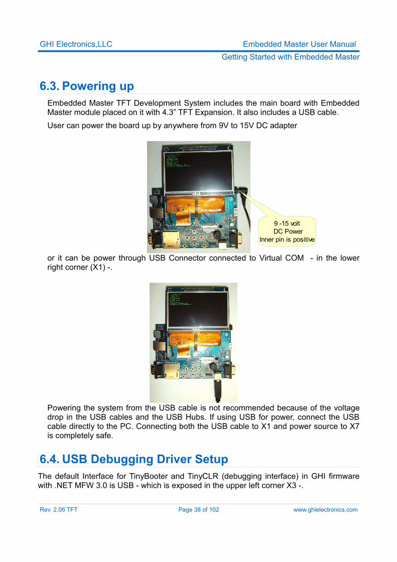
6.3. Powering upEmbedded Master TFT Development System includes the main board with Embedded Master module placed on it with 4.3” TFT Expansion. It also includes a USB cable.User can power the board up by anywhere from 9V to 15V DC adapter
or it can be power through USB Connector connected to Virtual COM - in the lower right corner (X1) -.
Powering the system from the USB cable is not recommended because of the voltage drop in the USB cables and the USB Hubs. If using USB for power, connect the USB cable directly to the PC. Connecting both the USB cable to X1 and power source to X7 is completely safe.
6.4. USB Debugging Driver SetupThe default Interface for TinyBooter and TinyCLR (debugging interface) in GHI firmware with .NET MFW 3.0 is USB - which is exposed in the upper left corner X3 -.
Rev. 2.06 TFT Page 38 of 102 www.ghielectronics.com
9 -15 volt DC Power
Inner pin is positive
GHI Electronics,LLC Embedded Master User ManualGetting Started with Embedded Master
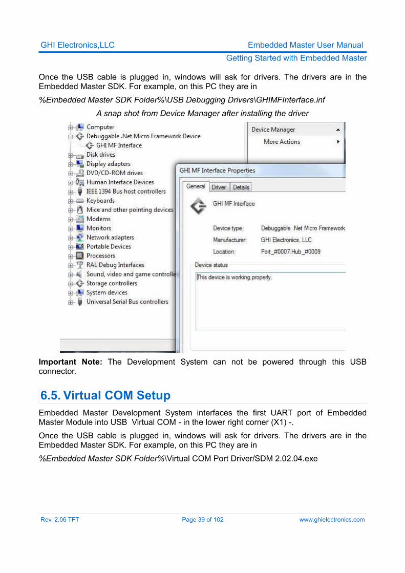
Once the USB cable is plugged in, windows will ask for drivers. The drivers are in the Embedded Master SDK. For example, on this PC they are in%Embedded Master SDK Folder%\USB Debugging Drivers\GHIMFInterface.inf
A snap shot from Device Manager after installing the driver
Important Note: The Development System can not be powered through this USB connector.
6.5. Virtual COM SetupEmbedded Master Development System interfaces the first UART port of Embedded Master Module into USB Virtual COM - in the lower right corner (X1) -. Once the USB cable is plugged in, windows will ask for drivers. The drivers are in the Embedded Master SDK. For example, on this PC they are in %Embedded Master SDK Folder%\Virtual COM Port Driver/SDM 2.02.04.exe
Rev. 2.06 TFT Page 39 of 102 www.ghielectronics.com
GHI Electronics,LLC Embedded Master User ManualGetting Started with Embedded Master
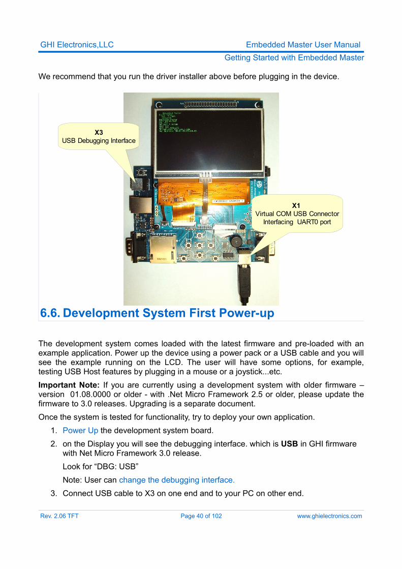
We recommend that you run the driver installer above before plugging in the device.
6.6. Development System First Power-up
The development system comes loaded with the latest firmware and pre-loaded with an example application. Power up the device using a power pack or a USB cable and you will see the example running on the LCD. The user will have some options, for example, testing USB Host features by plugging in a mouse or a joystick...etc.Important Note: If you are currently using a development system with older firmware – version 01.08.0000 or older - with .Net Micro Framework 2.5 or older, please update the firmware to 3.0 releases. Upgrading is a separate document.Once the system is tested for functionality, try to deploy your own application.
1. Power Up the development system board.2. on the Display you will see the debugging interface. which is USB in GHI firmware
with Net Micro Framework 3.0 release.Look for “DBG: USB” Note: User can change the debugging interface.
3. Connect USB cable to X3 on one end and to your PC on other end.
Rev. 2.06 TFT Page 40 of 102 www.ghielectronics.com
X1 Virtual COM USB Connector
Interfacing UART0 port
X3USB Debugging Interface
GHI Electronics,LLC Embedded Master User ManualGetting Started with Embedded Master
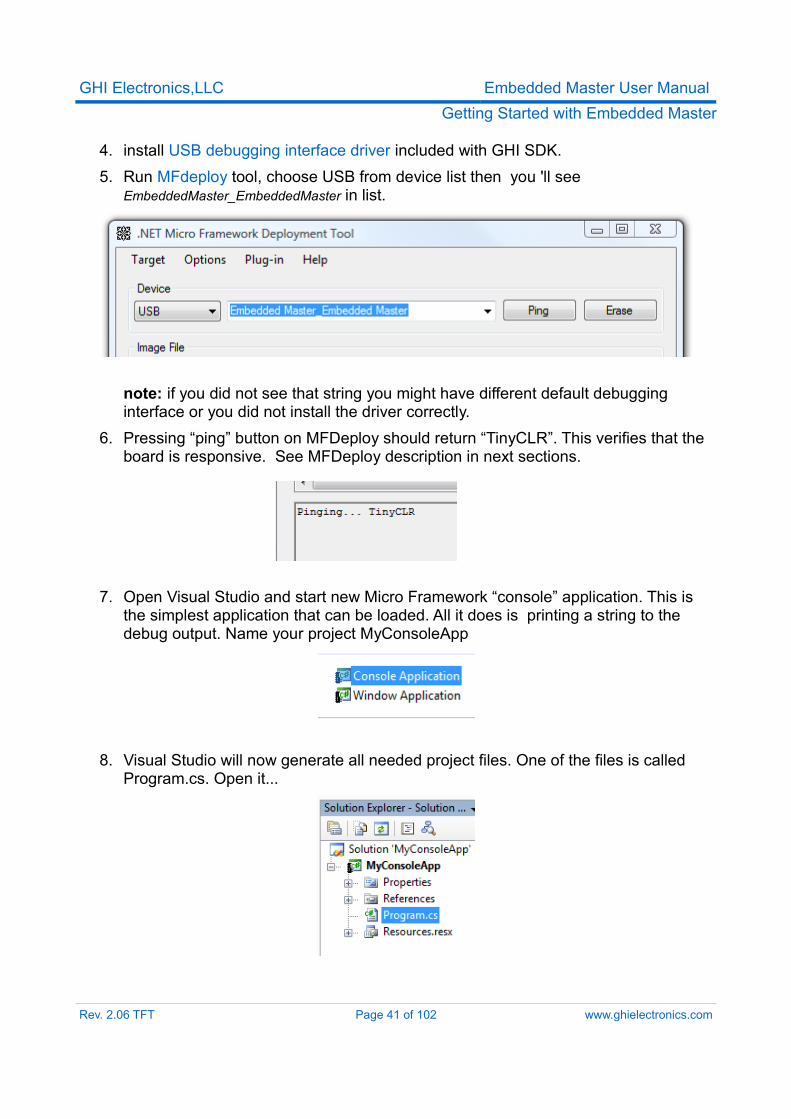
4. install USB debugging interface driver included with GHI SDK.5. Run MFdeploy tool, choose USB from device list then you 'll see
EmbeddedMaster_EmbeddedMaster in list.
note: if you did not see that string you might have different default debugging interface or you did not install the driver correctly.
6. Pressing “ping” button on MFDeploy should return “TinyCLR”. This verifies that the board is responsive. See MFDeploy description in next sections.
7. Open Visual Studio and start new Micro Framework “console” application. This is the simplest application that can be loaded. All it does is printing a string to the debug output. Name your project MyConsoleApp
8. Visual Studio will now generate all needed project files. One of the files is called Program.cs. Open it...
Rev. 2.06 TFT Page 41 of 102 www.ghielectronics.com
GHI Electronics,LLC Embedded Master User ManualGetting Started with Embedded Master
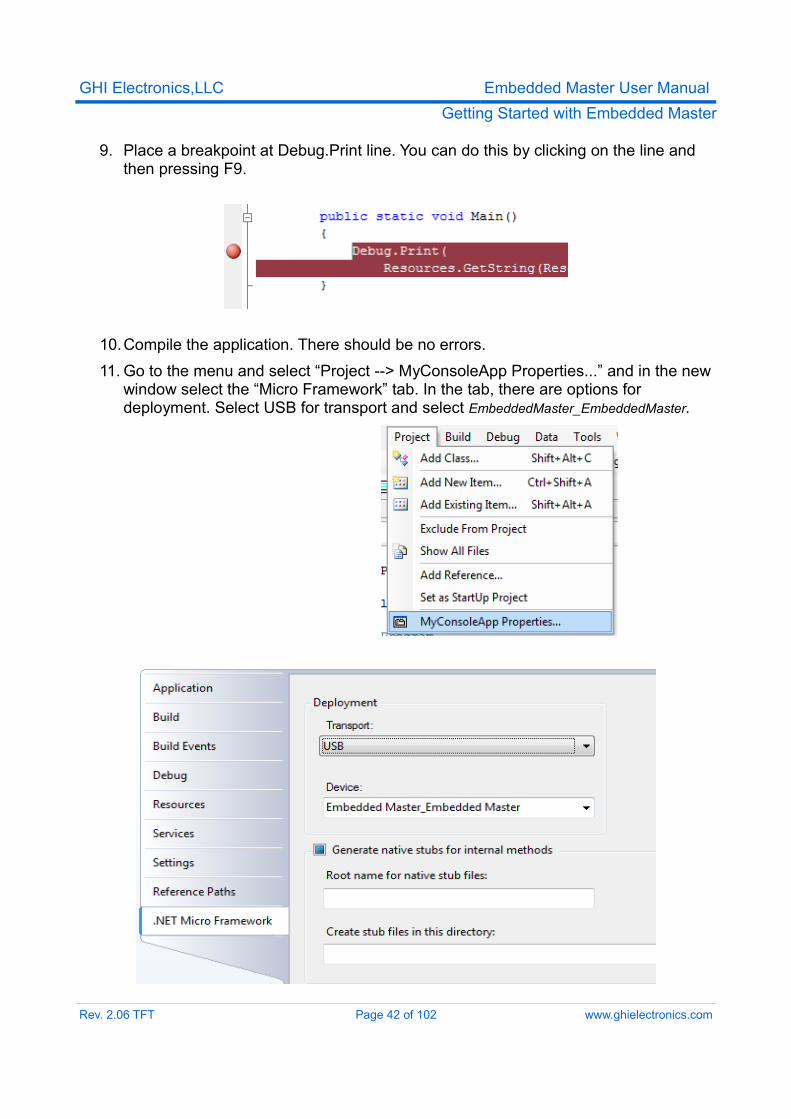
9. Place a breakpoint at Debug.Print line. You can do this by clicking on the line and then pressing F9.
10.Compile the application. There should be no errors.11. Go to the menu and select “Project --> MyConsoleApp Properties...” and in the new
window select the “Micro Framework” tab. In the tab, there are options for deployment. Select USB for transport and select EmbeddedMaster_EmbeddedMaster.
Rev. 2.06 TFT Page 42 of 102 www.ghielectronics.com
GHI Electronics,LLC Embedded Master User ManualGetting Started with Embedded Master
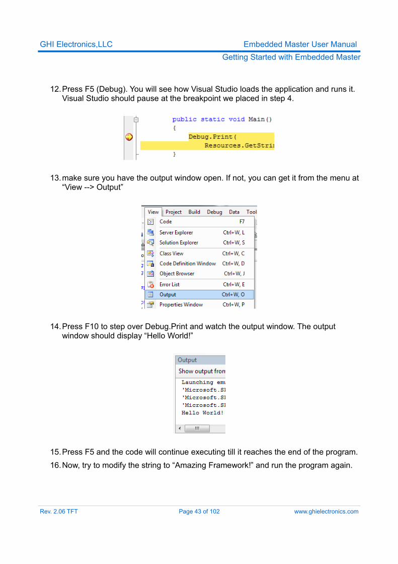
12.Press F5 (Debug). You will see how Visual Studio loads the application and runs it. Visual Studio should pause at the breakpoint we placed in step 4.
13.make sure you have the output window open. If not, you can get it from the menu at “View --> Output”
14.Press F10 to step over Debug.Print and watch the output window. The output window should display “Hello World!”
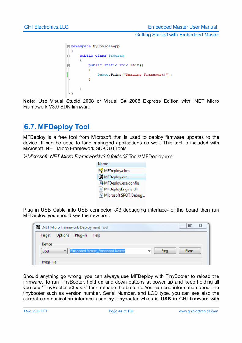
15.Press F5 and the code will continue executing till it reaches the end of the program.16.Now, try to modify the string to “Amazing Framework!” and run the program again.
Rev. 2.06 TFT Page 43 of 102 www.ghielectronics.com
GHI Electronics,LLC Embedded Master User ManualGetting Started with Embedded Master
Note: Use Visual Studio 2008 or Visual C# 2008 Express Edition with .NET Micro Framework V3.0 SDK firmware.
6.7. MFDeploy ToolMFDeploy is a free tool from Microsoft that is used to deploy firmware updates to the device. It can be used to load managed applications as well. This tool is included with Microsoft .NET Micro Framework SDK 3.0 Tools%Microsoft .NET Micro Framework\v3.0 folder%\Tools\MFDeploy.exe
Plug in USB Cable into USB connector -X3 debugging interface- of the board then run MFDeploy. you should see the new port.
Should anything go wrong, you can always use MFDeploy with TinyBooter to reload the firmware. To run TinyBooter, hold up and down buttons at power up and keep holding till you see “TinyBooter V3.x.x.x” then release the buttons. You can see information about the tinybooter such as version number, Serial Number, and LCD type. you can see also the currect communication interface used by Tinybooter which is USB in GHI firmware with
Rev. 2.06 TFT Page 44 of 102 www.ghielectronics.com
GHI Electronics,LLC Embedded Master User ManualGetting Started with Embedded Master
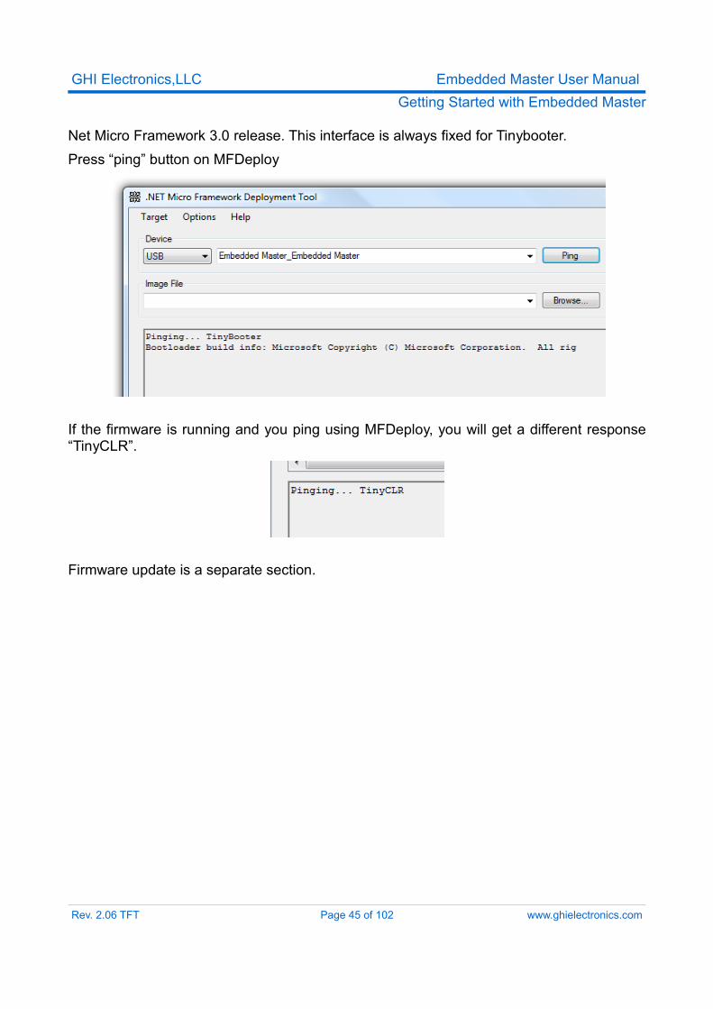
Net Micro Framework 3.0 release. This interface is always fixed for Tinybooter.Press “ping” button on MFDeploy
If the firmware is running and you ping using MFDeploy, you will get a different response “TinyCLR”.
Firmware update is a separate section.
Rev. 2.06 TFT Page 45 of 102 www.ghielectronics.com
GHI Electronics,LLC Embedded Master User ManualGetting Started with Embedded Master
6.8. Embedded Master LibraryMake sure you have the correct library included with your firmware. Otherwise, it will not load correctly.
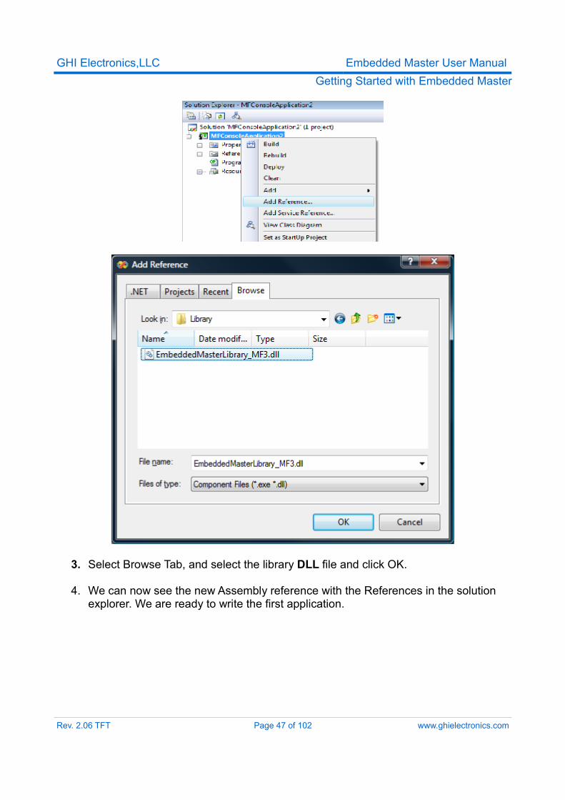
Embedded Master adds many functionalities on top of the .NET Micro Framework 3.0. For example, hardware peripherals such as CAN, Analog converters, PWM, ... are not supported in Micro Framework. However, they can be easily used with Embedded Master library.The library provides access for hardware peripherals, storage solutions, USB connectivity, and many other features.The library can be downloaded from GHI Electronics website as Assemblies files. These files must be added to your Visual Studio project in order to be able to use them.(Visual Studio Project --> Add Reference --> Choose Embedded Master Assemblies).
● USB Host Driver: Provides the ability to use various connected USB devices on low and high level. They include but not limited to: - USB Mass Storage.- USB HID Devices: Mouse, Keyboard, Joystick, etc.- Printers.- Serial Devices.- and many more...
● Hardware Extensions: Provides more hardware capabilities including but not limited to:- Analog Pins Access.- CAN Driver: CAN is very popular in the automotive industry.- PWM.
● and many more...
6.8.1 Adding the LibraryProceeding from the previous example, we will add GHI library to it and write a simple program.
1. Download the SDK which includes the Assemblies files for the library.2. Now, we need to add the library to our project. Go to the Menu and select “project
--> Add Reference...“.
Rev. 2.06 TFT Page 46 of 102 www.ghielectronics.com
GHI Electronics,LLC Embedded Master User ManualGetting Started with Embedded Master
3. Select Browse Tab, and select the library DLL file and click OK.
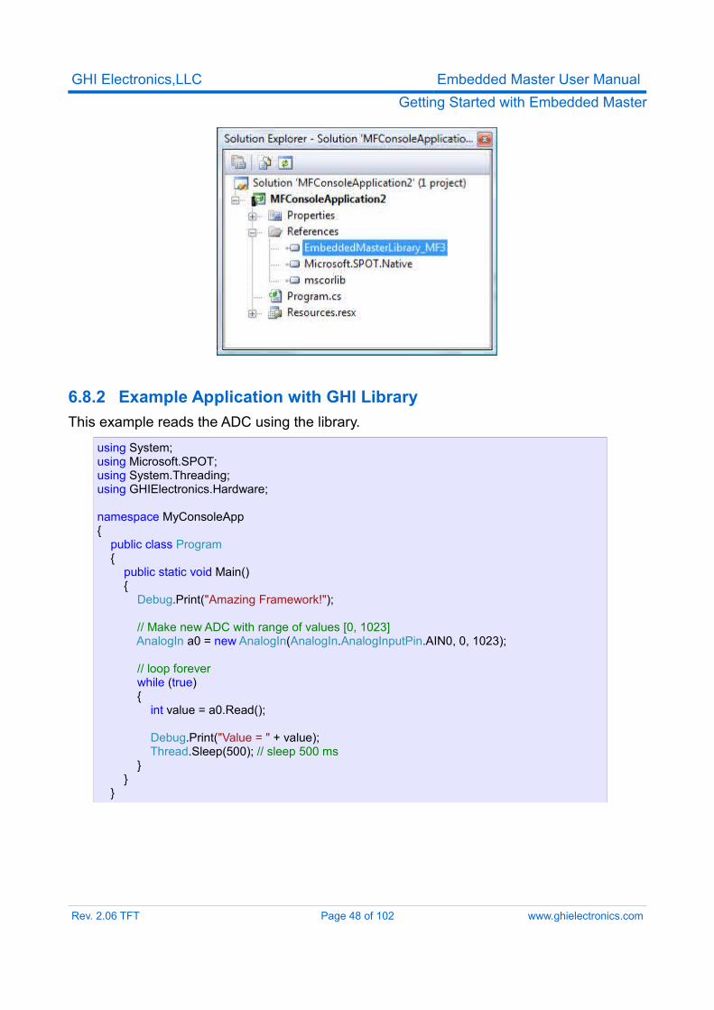
4. We can now see the new Assembly reference with the References in the solution explorer. We are ready to write the first application.
Rev. 2.06 TFT Page 47 of 102 www.ghielectronics.com
GHI Electronics,LLC Embedded Master User ManualGetting Started with Embedded Master
6.8.2 Example Application with GHI LibraryThis example reads the ADC using the library.
using System;using Microsoft.SPOT;using System.Threading;using GHIElectronics.Hardware;
namespace MyConsoleApp{ public class Program { public static void Main() { Debug.Print("Amazing Framework!");
// Make new ADC with range of values [0, 1023] AnalogIn a0 = new AnalogIn(AnalogIn.AnalogInputPin.AIN0, 0, 1023);
// loop forever while (true) { int value = a0.Read();
Debug.Print("Value = " + value); Thread.Sleep(500); // sleep 500 ms } } }
Rev. 2.06 TFT Page 48 of 102 www.ghielectronics.com
GHI Electronics,LLC Embedded Master User ManualDeveloping with the Emulator
7. Developing With The Emulator
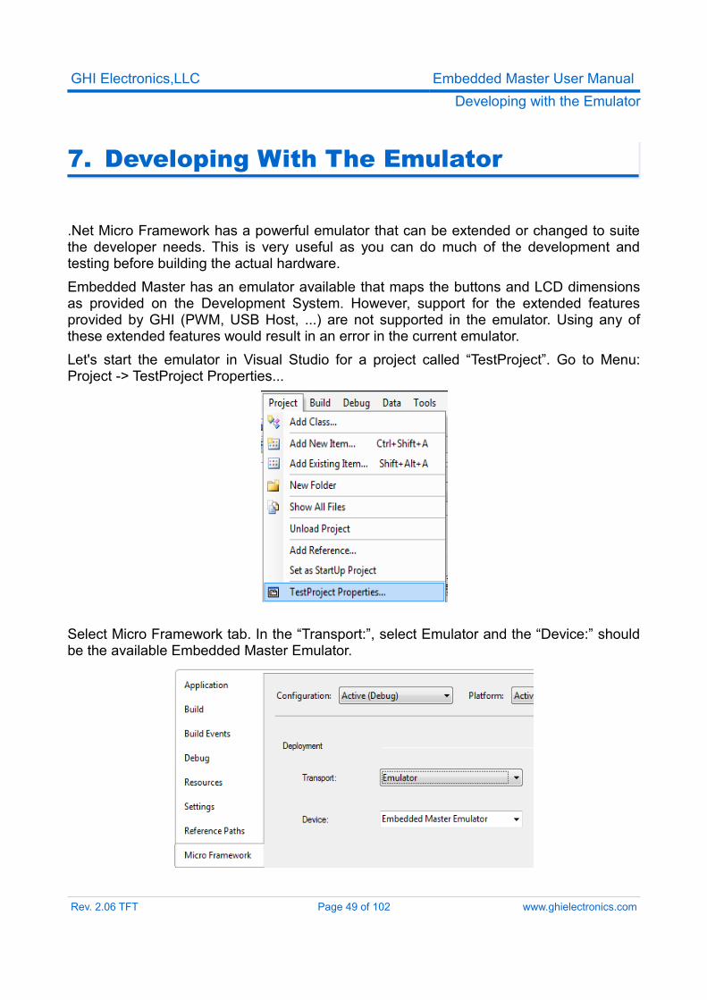
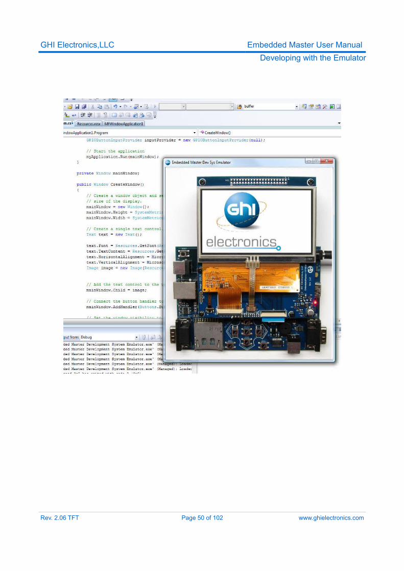
.Net Micro Framework has a powerful emulator that can be extended or changed to suite the developer needs. This is very useful as you can do much of the development and testing before building the actual hardware.Embedded Master has an emulator available that maps the buttons and LCD dimensions as provided on the Development System. However, support for the extended features provided by GHI (PWM, USB Host, ...) are not supported in the emulator. Using any of these extended features would result in an error in the current emulator.Let's start the emulator in Visual Studio for a project called “TestProject”. Go to Menu: Project -> TestProject Properties...
Select Micro Framework tab. In the “Transport:”, select Emulator and the “Device:” should be the available Embedded Master Emulator.
Rev. 2.06 TFT Page 49 of 102 www.ghielectronics.com
GHI Electronics,LLC Embedded Master User ManualDeveloping with the Emulator
Rev. 2.06 TFT Page 50 of 102 www.ghielectronics.com
GHI Electronics,LLC Embedded Master User ManualUpdating Embedded Master Firmware
8. Updating Embedded Master Firmware
Embedded Master includes GHI Loader, TinyBooter and TinyCLR which are three separate programs and they might have different version numbers.
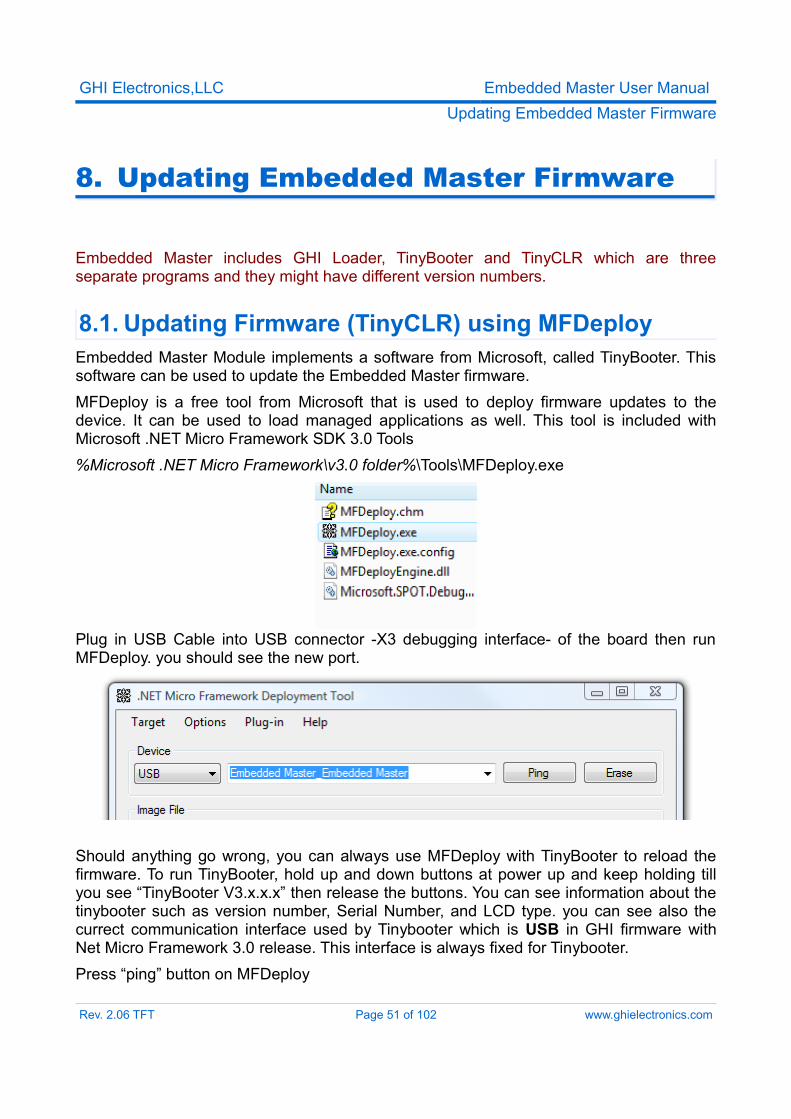
8.1. Updating Firmware (TinyCLR) using MFDeployEmbedded Master Module implements a software from Microsoft, called TinyBooter. This software can be used to update the Embedded Master firmware.MFDeploy is a free tool from Microsoft that is used to deploy firmware updates to the device. It can be used to load managed applications as well. This tool is included with Microsoft .NET Micro Framework SDK 3.0 Tools%Microsoft .NET Micro Framework\v3.0 folder%\Tools\MFDeploy.exe
Plug in USB Cable into USB connector -X3 debugging interface- of the board then run MFDeploy. you should see the new port.
Should anything go wrong, you can always use MFDeploy with TinyBooter to reload the firmware. To run TinyBooter, hold up and down buttons at power up and keep holding till you see “TinyBooter V3.x.x.x” then release the buttons. You can see information about the tinybooter such as version number, Serial Number, and LCD type. you can see also the currect communication interface used by Tinybooter which is USB in GHI firmware with Net Micro Framework 3.0 release. This interface is always fixed for Tinybooter.Press “ping” button on MFDeploy
Rev. 2.06 TFT Page 51 of 102 www.ghielectronics.com
GHI Electronics,LLC Embedded Master User ManualUpdating Embedded Master Firmware
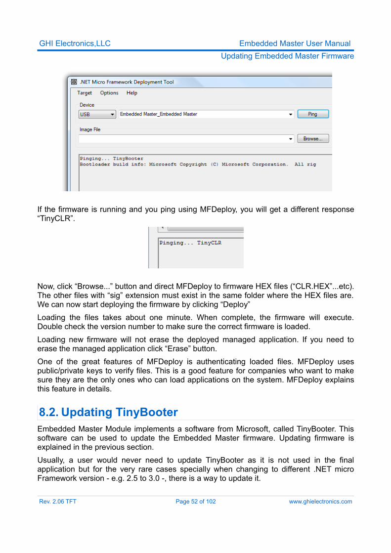
If the firmware is running and you ping using MFDeploy, you will get a different response “TinyCLR”.
Now, click “Browse...” button and direct MFDeploy to firmware HEX files (“CLR.HEX”...etc). The other files with “sig” extension must exist in the same folder where the HEX files are. We can now start deploying the firmware by clicking “Deploy”Loading the files takes about one minute. When complete, the firmware will execute. Double check the version number to make sure the correct firmware is loaded.Loading new firmware will not erase the deployed managed application. If you need to erase the managed application click “Erase” button.One of the great features of MFDeploy is authenticating loaded files. MFDeploy uses public/private keys to verify files. This is a good feature for companies who want to make sure they are the only ones who can load applications on the system. MFDeploy explains this feature in details.
8.2. Updating TinyBooterEmbedded Master Module implements a software from Microsoft, called TinyBooter. This software can be used to update the Embedded Master firmware. Updating firmware is explained in the previous section.Usually, a user would never need to update TinyBooter as it is not used in the final application but for the very rare cases specially when changing to different .NET micro Framework version - e.g. 2.5 to 3.0 -, there is a way to update it.
Rev. 2.06 TFT Page 52 of 102 www.ghielectronics.com
GHI Electronics,LLC Embedded Master User ManualUpdating Embedded Master Firmware
At power up, a GHI bootstrap and loader take over the processor and validates TinyBooter stored in FLASH. If TinyBooter was found and was valid, execution is transferred to TinyBooter, and from there to .NET Micro Framework.This piece of software is also accessible by user and provides many useful commands that help updating the Tinybooter. check GHI Loader section for more details.
Updating TinyBooter is not necessary and should not be done unless needed.TinyBooter update is necessary when upgrading or downgrading from Embedded Master .NET Micro Framework 2.5 to 3.0 firmwares.
9. GHI Loader
GHI Loader is the initial piece of software that runs on system power up.At power up, a GHI bootstrap and loader take over the processor and validates TinyBooter stored in FLASH. If TinyBooter was found and was valid, execution is transferred to TinyBooter, and from there to .NET Micro Framework.This software is also accessible by user and provides many useful commands.
9.1. Entering GHI Loader User Interface
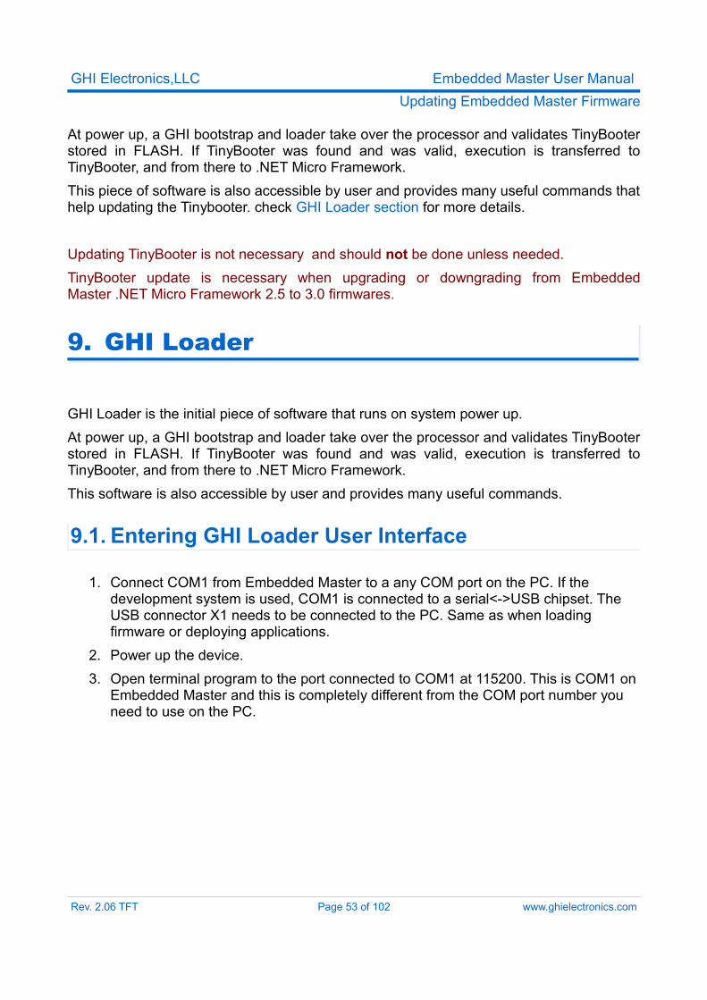
1. Connect COM1 from Embedded Master to a any COM port on the PC. If the development system is used, COM1 is connected to a serial<->USB chipset. The USB connector X1 needs to be connected to the PC. Same as when loading firmware or deploying applications.
2. Power up the device.3. Open terminal program to the port connected to COM1 at 115200. This is COM1 on
Embedded Master and this is completely different from the COM port number you need to use on the PC.
Rev. 2.06 TFT Page 53 of 102 www.ghielectronics.com
GHI Electronics,LLC Embedded Master User ManualGHI Loader
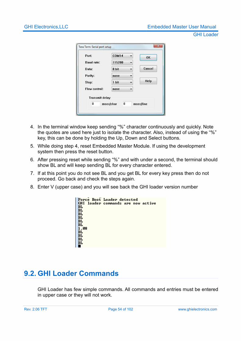
4. In the terminal window keep sending “%” character continuously and quickly. Note the quotes are used here just to isolate the character. Also, instead of using the “%” key, this can be done by holding the Up, Down and Select buttons.
5. While doing step 4, reset Embedded Master Module. If using the development system then press the reset button.
6. After pressing reset while sending “%” and with under a second, the terminal should show BL and will keep sending BL for every character entered.
7. If at this point you do not see BL and you get BL for every key press then do not proceed. Go back and check the steps again.
8. Enter V (upper case) and you will see back the GHI loader version number
9.2. GHI Loader Commands
GHI Loader has few simple commands. All commands and entries must be entered in upper case or they will not work.
Rev. 2.06 TFT Page 54 of 102 www.ghielectronics.com
GHI Electronics,LLC Embedded Master User ManualGHI Loader
Command DescriptionV Get GHI Loader version numberE Erase all memory. Should NOT be used, unless, the
user is sure that this step is needed.X Load new TinyBooter. See details below.N Display serial numberR Run TinyBooter (exit GHI loader)
Before updating TinyBooter, it would be very wise to check and write down the version numbers of everything, assuming the device is functional.
1. The .NET Micro Framework version number is displayed at power up on the LCD and it can be also obtained using GHI native methods.
2. TinyBooter version is displayed when the user force TinyBooter at power up. You can force TinyBooter by holding UP and DOWN buttons and then pressing reset.
3. The GHI Loader version number can be obtained by sending V command.
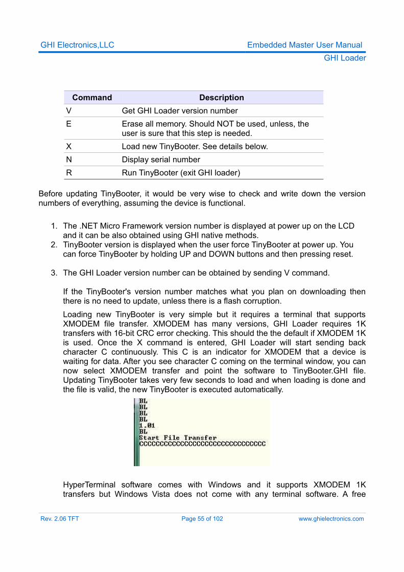
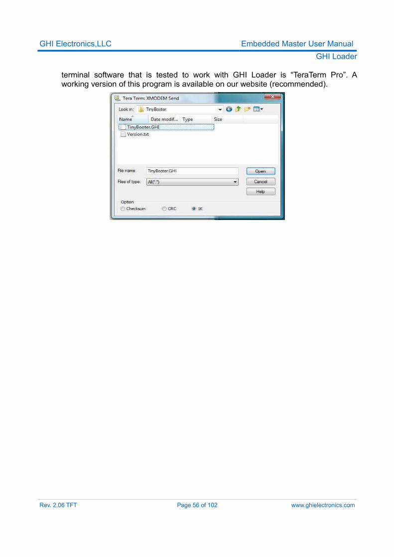
If the TinyBooter's version number matches what you plan on downloading then there is no need to update, unless there is a flash corruption.Loading new TinyBooter is very simple but it requires a terminal that supports XMODEM file transfer. XMODEM has many versions, GHI Loader requires 1K transfers with 16-bit CRC error checking. This should the the default if XMODEM 1K is used. Once the X command is entered, GHI Loader will start sending back character C continuously. This C is an indicator for XMODEM that a device is waiting for data. After you see character C coming on the terminal window, you can now select XMODEM transfer and point the software to TinyBooter.GHI file. Updating TinyBooter takes very few seconds to load and when loading is done and the file is valid, the new TinyBooter is executed automatically.
HyperTerminal software comes with Windows and it supports XMODEM 1K transfers but Windows Vista does not come with any terminal software. A free
Rev. 2.06 TFT Page 55 of 102 www.ghielectronics.com
GHI Electronics,LLC Embedded Master User ManualGHI Loader
terminal software that is tested to work with GHI Loader is “TeraTerm Pro”. A working version of this program is available on our website (recommended).
Rev. 2.06 TFT Page 56 of 102 www.ghielectronics.com
GHI Electronics,LLC Embedded Master User ManualSelecting the Debug Interface
10. Selecting The Debug Interface
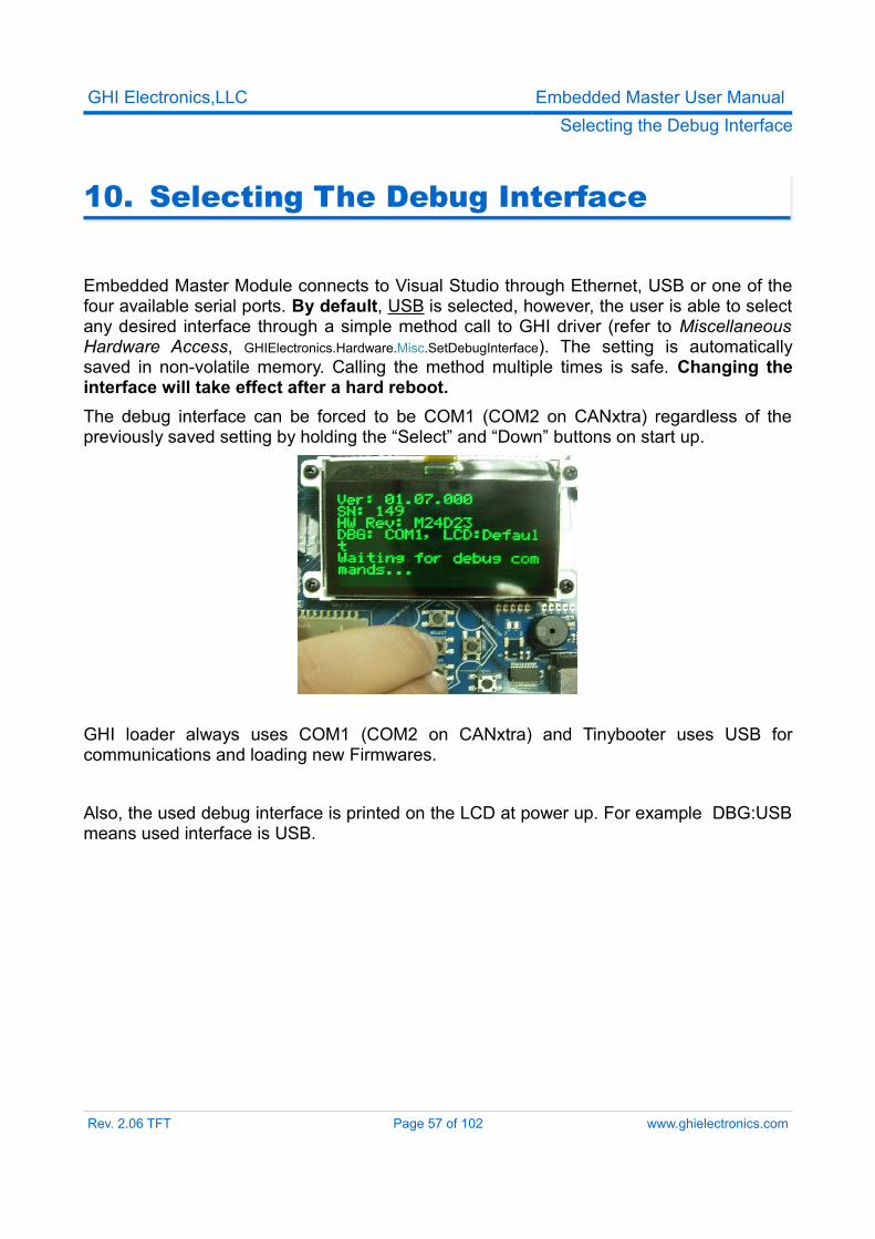
Embedded Master Module connects to Visual Studio through Ethernet, USB or one of the four available serial ports. By default, USB is selected, however, the user is able to select any desired interface through a simple method call to GHI driver (refer to Miscellaneous Hardware Access, GHIElectronics.Hardware.Misc.SetDebugInterface). The setting is automatically saved in non-volatile memory. Calling the method multiple times is safe. Changing the interface will take effect after a hard reboot.The debug interface can be forced to be COM1 (COM2 on CANxtra) regardless of the previously saved setting by holding the “Select” and “Down” buttons on start up.
GHI loader always uses COM1 (COM2 on CANxtra) and Tinybooter uses USB for communications and loading new Firmwares.
Also, the used debug interface is printed on the LCD at power up. For example DBG:USB means used interface is USB.
Rev. 2.06 TFT Page 57 of 102 www.ghielectronics.com
GHI Electronics,LLC Embedded Master User ManualHardware and Software Library
11. Hardware And Software Library
There are many libraries included with Embedded Master. This section will give a full description of Embedded Master Hardware and peripherals and a general overview on the related libraries and what is supported. Developers should consult the library reference, which is is in a separate document.
11.1. GraphicsThe TFT version of Embedded Master Module adds an interface for TFT displays. TFT display refresh is all done through DMA with no processor utilization. The display connector is designed to plug directly into Sharp 4.3” (480x272) LQ043T1DG01 display. These displays are very common and similar to what is used in Sony PSP. A developer can also select to use a different TFT display. In this case, the display connector should be connected to a cable to another circuit board. The second board will have all circuitry needed to run the connected TFT display, such as VCOM and back-light power supply. Micro Framework requires 5:6:5 RGB color mapping display.Embedded Master TFT modules supports TFT displays and still keeps the support for the SPI2 based displays. Users can select between a colorful TFT display or a low-cost 128x64 one-color displays.Developers can use the library to write directly to the processor registers; therefore, tweak the display settings.GHI library lets users select one of the supported display drivers. Users can use one of them as a base and then change the timing requirements for their use TFT display if needed.The supported TFT configurations are:
1. 480x272: Default.2. QVGA 320x240: This is a smaller LCD that can provide a better performance for
some graphics applications such as continuously moving objects on the LCD.3. VGA 480x480: Can be used to connect Embedded Master to a VGA monitor. This
option uses standard VGA timing for 640x480 (supported by all monitors) but Embedded Master simulate this at 480x480 pixels. This is done to slow the refresh rate on Embedded Master and provide a better performance. As far as the monitor is concerned, this is the standard 640x480 but when you draw to the screen the images will be slightly stretched.
4. 240x320: This is for a smaller Portrait position LCD.Refer to Pin-out description section for the 0.5mm TFT display header pin-out table
Rev. 2.06 TFT Page 58 of 102 www.ghielectronics.com
GHI Electronics,LLC Embedded Master User ManualHardware and Software Library
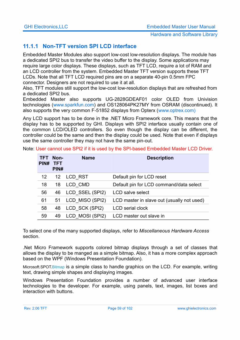
11.1.1 Non-TFT version SPI LCD interfaceEmbedded Master Modules also support low-cost low-resolution displays. The module has a dedicated SPI2 bus to transfer the video buffer to the display. Some applications may require large color displays. These displays, such as TFT LCD, require a lot of RAM and an LCD controller from the system. Embedded Master TFT version supports these TFT LCDs. Note that all TFT LCD required pins are on a separate 40-pin 0.5mm FPC connector. Designers are not required to use it at all.Also, TFT modules still support the low-cost low-resolution displays that are refreshed from a dedicated SPI2 bus.Embedded Master also supports UG-2828GDEAF01 color OLED from Univision technologies (www.sparkfun.com) and OS128064PK27MY from OSRAM (discontinued). It also supports the very common F-51852 displays from Opterx (www.optrex.com)Any LCD support has to be done in the .NET Micro Framework core. This means that the display has to be supported by GHI. Displays with SPI2 interface usually contain one of the common LCD/OLED controllers. So even though the display can be different, the controller could be the same and then the display could be used. Note that even if displays use the same controller they may not have the same pin-out.Note: User cannot use SPI2 if it is used by the SPI-based Embedded Master LCD Driver.
TFT PIN#
Non-TFTPIN#
Name Description
12 12 LCD_RST Default pin for LCD reset18 18 LCD_CMD Default pin for LCD command/data select56 46 LCD_SSEL (SPI2) LCD salve select61 51 LCD_MISO (SPI2) LCD master in slave out (usually not used)58 48 LCD_SCK (SPI2) LCD serial clock59 49 LCD_MOSI (SPI2) LCD master out slave in
To select one of the many supported displays, refer to Miscellaneous Hardware Access section.
.Net Micro Framework supports colored bitmap displays through a set of classes that allows the display to be manged as a simple bitmap. Also, it has a more complex approach based on the WPF (Windows Presentation Foundation).Microsoft.SPOT.Bitmap is a simple class to handle graphics on the LCD. For example, writing text, drawing simple shapes and displaying images.Windows Presentation Foundation provides a number of advanced user interface technologies to the developer. For example, using panels, text, images, list boxes and interaction with buttons.
Rev. 2.06 TFT Page 59 of 102 www.ghielectronics.com
GHI Electronics,LLC Embedded Master User ManualHardware and Software Library
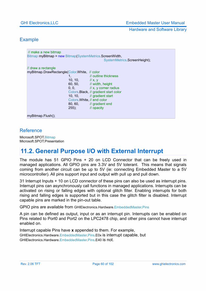
Example
// make a new bitmap Bitmap myBitmap = new Bitmap(SystemMetrics.ScreenWidth,
SystemMetrics.ScreenHeight);
// draw a rectangle myBitmap.DrawRectangle(Color.White, // color
1, // outline thickness 10, 10, // x, y 60, 50, // width, height 0, 0, // x, y corner radius Colors.Black, // gradient start color 10, 10, // gradient start Colors.White, // end color 80, 60, // gradient end 255); // opacity
myBitmap.Flush();
ReferenceMicrosoft.SPOT.BitmapMicrosoft.SPOT.Presentation
11.2. General Purpose I/O with External InterruptThe module has 51 GPIO Pins + 20 on LCD Connector that can be freely used in managed applications. All GPIO pins are 3.3V and 5V tolerant. This means that signals coming from another circuit can be up to 5V (ie: connecting Embedded Master to a 5V microcontroller). All pins support input and output with pull up and pull down.31 Interrupt Inputs + 10 on LCD connector of these pins can also be used as interrupt pins. Interrupt pins can asynchronously call functions in managed applications. Interrupts can be activated on rising or falling edges with optional glitch filter. Enabling interrupts for both rising and falling edges is supported but in this case the glitch filter is disabled. Interrupt capable pins are marked in the pin-out table.GPIO pins are available from GHIElectronics.Hardware.EmbeddedMaster.Pins
A pin can be defined as output, input or as an interrupt pin. Interrupts can be enabled on Pins related to Port0 and Port2 on the LPC2478 chip, and other pins cannot have interrupt enabled on.Interrupt capable Pins have x appended to them. For example, GHIElectronics.Hardware.EmbeddedMaster.Pins.E0x is interrupt capable, but GHIElectronics.Hardware.EmbeddedMaster.Pins.E40 is not.
Rev. 2.06 TFT Page 60 of 102 www.ghielectronics.com
GHI Electronics,LLC Embedded Master User ManualHardware and Software Library
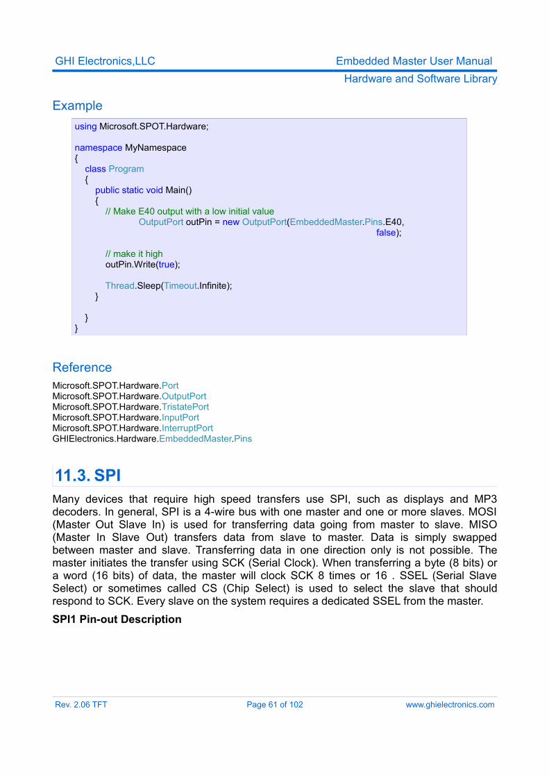
Exampleusing Microsoft.SPOT.Hardware;
namespace MyNamespace{ class Program { public static void Main() { // Make E40 output with a low initial value
OutputPort outPin = new OutputPort(EmbeddedMaster.Pins.E40, false);
// make it high outPin.Write(true); Thread.Sleep(Timeout.Infinite); } }}
ReferenceMicrosoft.SPOT.Hardware.PortMicrosoft.SPOT.Hardware.OutputPort Microsoft.SPOT.Hardware.TristatePort Microsoft.SPOT.Hardware.InputPort Microsoft.SPOT.Hardware.InterruptPort GHIElectronics.Hardware.EmbeddedMaster.Pins
11.3. SPIMany devices that require high speed transfers use SPI, such as displays and MP3 decoders. In general, SPI is a 4-wire bus with one master and one or more slaves. MOSI (Master Out Slave In) is used for transferring data going from master to slave. MISO (Master In Slave Out) transfers data from slave to master. Data is simply swapped between master and slave. Transferring data in one direction only is not possible. The master initiates the transfer using SCK (Serial Clock). When transferring a byte (8 bits) or a word (16 bits) of data, the master will clock SCK 8 times or 16 . SSEL (Serial Slave Select) or sometimes called CS (Chip Select) is used to select the slave that should respond to SCK. Every slave on the system requires a dedicated SSEL from the master.SPI1 Pin-out Description
Rev. 2.06 TFT Page 61 of 102 www.ghielectronics.com
GHI Electronics,LLC Embedded Master User ManualHardware and Software Library
PIN# TFT# Name Description37 47 SPI1_MOSI SPI1 Master Out Slave In38 48 SPI1_MISO SPI1 Master In Slave Out39 49 SPI1_SSEL SPI1 Slave Select40 50 SPI1_SCK SPI1 Serial Clock
SPI2 Pin-out DescriptionUser cannot use SPI2 if it is used by the SPI-based Embedded Master LCD Driver.
PIN# TFT# Name Description49 59 (LCD)SPI2_MOSI SPI2 Master Out Slave In51 48 (LCD)SPI2_MISO SPI2 Master In Slave Out46 56 (LCD)SPI2_SSEL SPI2 Slave Select48 58 (LCD)SPI2_SCK SPI2 Serial Clock
Embedded Master supports two SPIs, one is dedicated for the LCD (SPI.SPI_module.SPI2) but user can use it if not using SPI based LCD and the other one is available to the user which is SSP0 on the LPC2478 chip. SPI Module (SPI.SPI_module.SPI1).The SPI.Configuration class constructor takes several arguments, note that ChipSelect_HoldTime and ChipSelect_SetupTime are not supported.
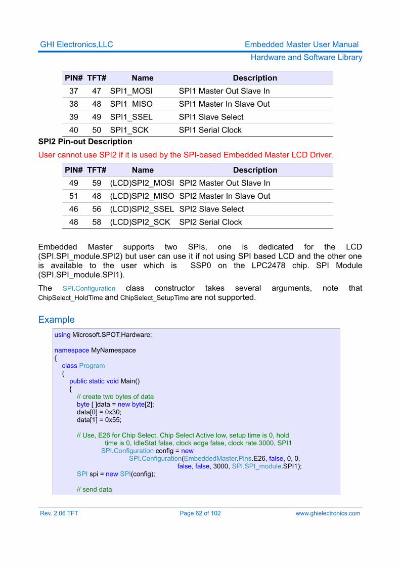
Example using Microsoft.SPOT.Hardware;
namespace MyNamespace{ class Program { public static void Main() { // create two bytes of data byte [ ]data = new byte[2]; data[0] = 0x30; data[1] = 0x55;
// Use, E26 for Chip Select, Chip Select Active low, setup time is 0, hold time is 0, IdleStat false, clock edge false, clock rate 3000, SPI1
SPI.Configuration config = new SPI.Configuration(EmbeddedMaster.Pins.E26, false, 0, 0,
false, false, 3000, SPI.SPI_module.SPI1); SPI spi = new SPI(config);
// send data
Rev. 2.06 TFT Page 62 of 102 www.ghielectronics.com
GHI Electronics,LLC Embedded Master User ManualHardware and Software Library
spi.Write(data);
Thread.Sleep(Timeout.Infinite); } }}
ReferenceMicrosoft.SPOT.Hardware.SPI
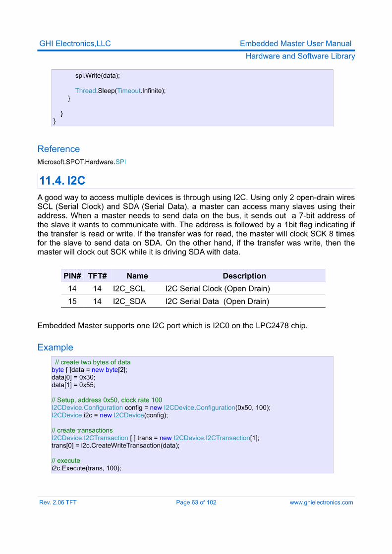
11.4. I2CA good way to access multiple devices is through using I2C. Using only 2 open-drain wires SCL (Serial Clock) and SDA (Serial Data), a master can access many slaves using their address. When a master needs to send data on the bus, it sends out a 7-bit address of the slave it wants to communicate with. The address is followed by a 1bit flag indicating if the transfer is read or write. If the transfer was for read, the master will clock SCK 8 times for the slave to send data on SDA. On the other hand, if the transfer was write, then the master will clock out SCK while it is driving SDA with data.
PIN# TFT# Name Description14 14 I2C_SCL I2C Serial Clock (Open Drain)15 14 I2C_SDA I2C Serial Data (Open Drain)
Embedded Master supports one I2C port which is I2C0 on the LPC2478 chip.
Example // create two bytes of data
byte [ ]data = new byte[2]; data[0] = 0x30; data[1] = 0x55;
// Setup, address 0x50, clock rate 100 I2CDevice.Configuration config = new I2CDevice.Configuration(0x50, 100); I2CDevice i2c = new I2CDevice(config); // create transactions I2CDevice.I2CTransaction [ ] trans = new I2CDevice.I2CTransaction[1]; trans[0] = i2c.CreateWriteTransaction(data);
// execute i2c.Execute(trans, 100);
Rev. 2.06 TFT Page 63 of 102 www.ghielectronics.com
GHI Electronics,LLC Embedded Master User ManualHardware and Software Library
ReferenceMicrosoft.SPOT.Hardware.I2CDevice
11.5. UARTOne of the oldest and most common protocols is UART (or USART). TX is the serial data transmitted and RX is the data received. UART is actually what is used on serial (COM) ports on computers. The difference between UART on Embedded Master and a serial port on a PC is that Embedded Master’s UART pins have 3.3V TTL levels where the PC uses RS232 levels. For proper communication, an RS232 level converter is required. One of the most common converters is MAX232. If UART is connected between 2 TTL circuits, no level converter is needed but they should be connected as a null modem. Null modem means RX on one circuit is connected to TX on the other circuit, and vice versa.When 2 nodes want to communicate over UART, a predefined baud rate should be used on both sides. Baud rate is how many bits per second are transferred on the bus.Embedded Master Module hardware supports 4 COM ports, however, the user is able to have many more COM ports using USB serial chipsets. For example, there are many USB <--> Serial cables available and these can be connected directly to Embedded Master. Check Supported Devices Section.Maximum Baudrate supported by .Net Micro Framework is 115200. However, any baudrate can be set using the processor registers directly (GHIElectronics.Hardware.Register). The maximum baudrate is 9 Mhz. An example is provided later in this section.
PIN# TFT# Name Description5 5 UART_RXD0 UART 0 (COM1) data receive input6 6 UART_TXD0 UART 0 (COM1) data transmit output45 55 UART_RXD1 UART 1 (COM2) data receive pin50 60 UART_TXD1 UART 1 (COM2) transmit data output44 54 UART_RTS1 UART 1 (COM2) RTS hardware
handshaking47 57 UART_CTS1 UART 1 (COM2) CTS hardware
handshaking41 51 UART_RXD2 UART 2 (COM3) receive data input42 52 UART_TXD2 UART 2 (COM3) transmit data output10 10 UART_RXD3 UART 3 (COM4) data receive input9 9 UART_TXD3 UART 3 (COM4) data transmit output
The following COM ports are available:
Rev. 2.06 TFT Page 64 of 102 www.ghielectronics.com
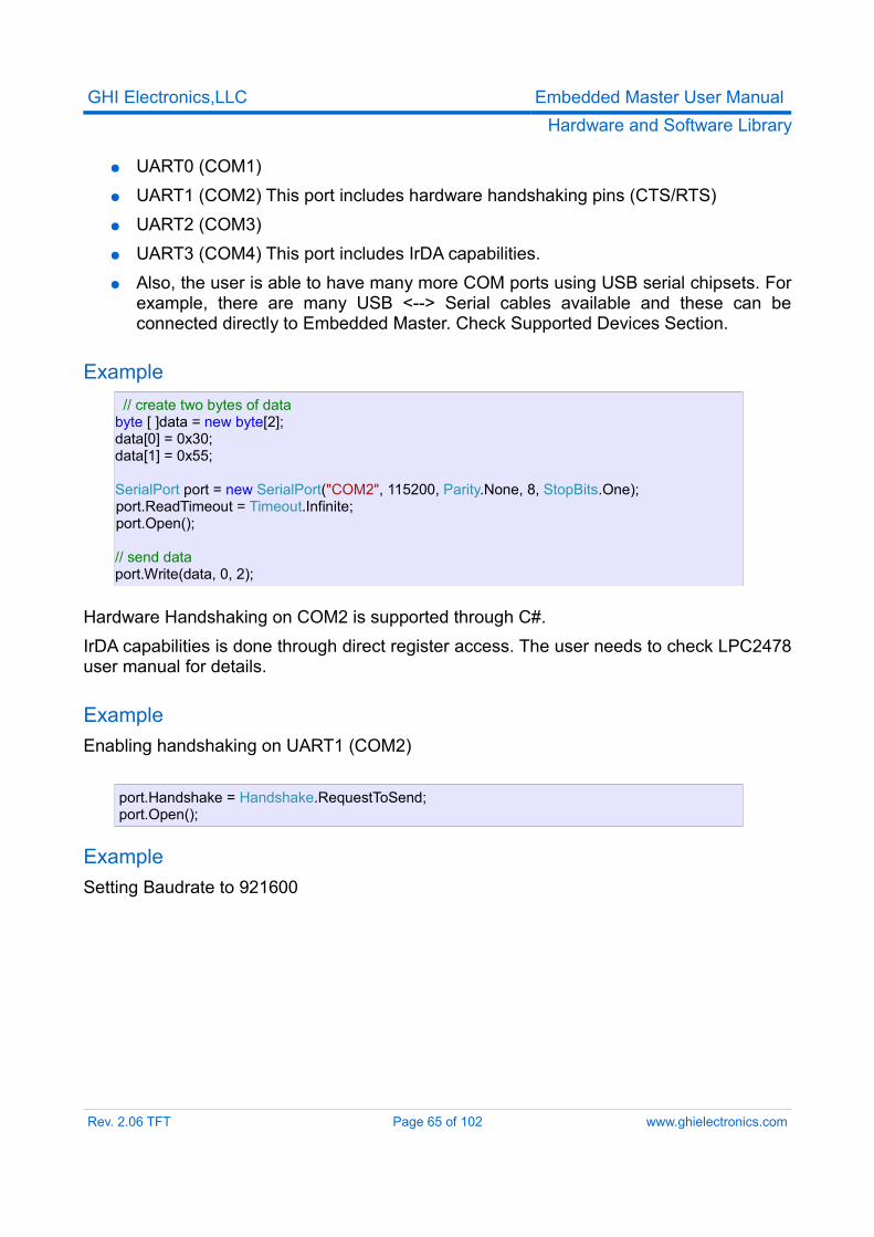
GHI Electronics,LLC Embedded Master User ManualHardware and Software Library
● UART0 (COM1)● UART1 (COM2) This port includes hardware handshaking pins (CTS/RTS)● UART2 (COM3)● UART3 (COM4) This port includes IrDA capabilities.● Also, the user is able to have many more COM ports using USB serial chipsets. For
example, there are many USB <--> Serial cables available and these can be connected directly to Embedded Master. Check Supported Devices Section.
Example // create two bytes of data
byte [ ]data = new byte[2]; data[0] = 0x30; data[1] = 0x55;
SerialPort port = new SerialPort("COM2", 115200, Parity.None, 8, StopBits.One); port.ReadTimeout = Timeout.Infinite; port.Open();
// send data port.Write(data, 0, 2);
Hardware Handshaking on COM2 is supported through C#.IrDA capabilities is done through direct register access. The user needs to check LPC2478 user manual for details.
ExampleEnabling handshaking on UART1 (COM2)
port.Handshake = Handshake.RequestToSend;port.Open();
ExampleSetting Baudrate to 921600
Rev. 2.06 TFT Page 65 of 102 www.ghielectronics.com
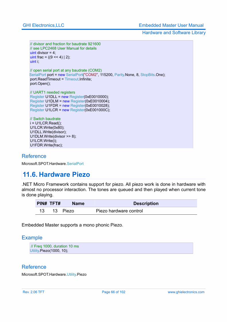
GHI Electronics,LLC Embedded Master User ManualHardware and Software Library
// divisor and fraction for baudrate 921600 // see LPC2468 User Manual for details uint divisor = 4; uint frac = ((9 << 4) | 2); uint i;
// open serial port at any baudrate (COM2) SerialPort port = new SerialPort("COM2", 115200, Parity.None, 8, StopBits.One); port.ReadTimeout = Timeout.Infinite; port.Open();
// UART1 needed registers Register U1DLL = new Register(0xE0010000); Register U1DLM = new Register(0xE0010004); Register U1FDR = new Register(0xE0010028); Register U1LCR = new Register(0xE001000C);
// Switch baudrate i = U1LCR.Read(); U1LCR.Write(0x80); U1DLL.Write(divisor); U1DLM.Write(divisor >> 8); U1LCR.Write(i); U1FDR.Write(frac);
ReferenceMicrosoft.SPOT.Hardware.SerialPort
11.6. Hardware Piezo.NET Micro Framework contains support for piezo. All piezo work is done in hardware with almost no processor interaction. The tones are queued and then played when current tone is done playing.
PIN# TFT# Name Description13 13 Piezo Piezo hardware control
Embedded Master supports a mono phonic Piezo.
Example// Freq 1000, duration 10 ms
Utility.Piezo(1000, 10);
ReferenceMicrosoft.SPOT.Hardware.Utility.Piezo
Rev. 2.06 TFT Page 66 of 102 www.ghielectronics.com
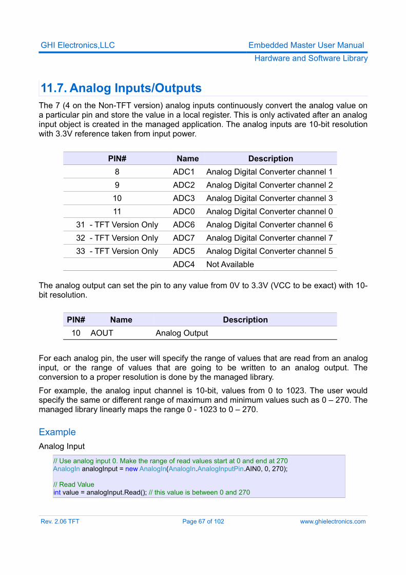
GHI Electronics,LLC Embedded Master User ManualHardware and Software Library
11.7. Analog Inputs/OutputsThe 7 (4 on the Non-TFT version) analog inputs continuously convert the analog value on a particular pin and store the value in a local register. This is only activated after an analog input object is created in the managed application. The analog inputs are 10-bit resolution with 3.3V reference taken from input power.
PIN# Name Description8 ADC1 Analog Digital Converter channel 19 ADC2 Analog Digital Converter channel 210 ADC3 Analog Digital Converter channel 311 ADC0 Analog Digital Converter channel 0
31 - TFT Version Only ADC6 Analog Digital Converter channel 632 - TFT Version Only ADC7 Analog Digital Converter channel 733 - TFT Version Only ADC5 Analog Digital Converter channel 5
ADC4 Not Available
The analog output can set the pin to any value from 0V to 3.3V (VCC to be exact) with 10-bit resolution.
PIN# Name Description10 AOUT Analog Output
For each analog pin, the user will specify the range of values that are read from an analog input, or the range of values that are going to be written to an analog output. The conversion to a proper resolution is done by the managed library.For example, the analog input channel is 10-bit, values from 0 to 1023. The user would specify the same or different range of maximum and minimum values such as 0 – 270. The managed library linearly maps the range 0 - 1023 to 0 – 270.
ExampleAnalog Input
// Use analog input 0. Make the range of read values start at 0 and end at 270 AnalogIn analogInput = new AnalogIn(AnalogIn.AnalogInputPin.AIN0, 0, 270);
// Read Value int value = analogInput.Read(); // this value is between 0 and 270
Rev. 2.06 TFT Page 67 of 102 www.ghielectronics.com
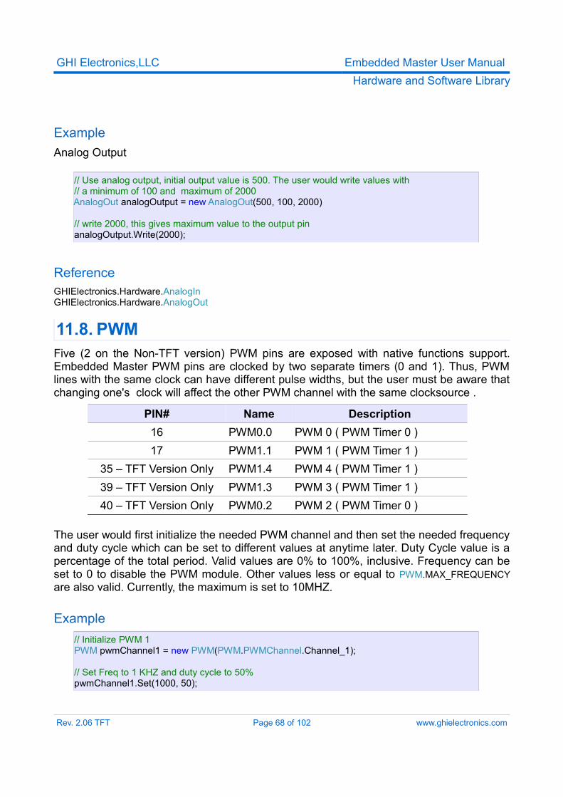
GHI Electronics,LLC Embedded Master User ManualHardware and Software Library
ExampleAnalog Output
// Use analog output, initial output value is 500. The user would write values with // a minimum of 100 and maximum of 2000 AnalogOut analogOutput = new AnalogOut(500, 100, 2000)
// write 2000, this gives maximum value to the output pin analogOutput.Write(2000);
ReferenceGHIElectronics.Hardware.AnalogInGHIElectronics.Hardware.AnalogOut
11.8. PWMFive (2 on the Non-TFT version) PWM pins are exposed with native functions support. Embedded Master PWM pins are clocked by two separate timers (0 and 1). Thus, PWM lines with the same clock can have different pulse widths, but the user must be aware that changing one's clock will affect the other PWM channel with the same clocksource .
PIN# Name Description16 PWM0.0 PWM 0 ( PWM Timer 0 )17 PWM1.1 PWM 1 ( PWM Timer 1 )
35 – TFT Version Only PWM1.4 PWM 4 ( PWM Timer 1 )39 – TFT Version Only PWM1.3 PWM 3 ( PWM Timer 1 )40 – TFT Version Only PWM0.2 PWM 2 ( PWM Timer 0 )
The user would first initialize the needed PWM channel and then set the needed frequency and duty cycle which can be set to different values at anytime later. Duty Cycle value is a percentage of the total period. Valid values are 0% to 100%, inclusive. Frequency can be set to 0 to disable the PWM module. Other values less or equal to PWM.MAX_FREQUENCY are also valid. Currently, the maximum is set to 10MHZ.
Example // Initialize PWM 1 PWM pwmChannel1 = new PWM(PWM.PWMChannel.Channel_1);
// Set Freq to 1 KHZ and duty cycle to 50% pwmChannel1.Set(1000, 50);
Rev. 2.06 TFT Page 68 of 102 www.ghielectronics.com
GHI Electronics,LLC Embedded Master User ManualHardware and Software Library
ReferenceGHIElectronics.Hardware.PWM
11.9. Processor Register AccessEmbedded Master Module allows direct access to the LPC2468/78 registers. The user can write, read or manipulate the bits as needed. This can be very useful to enable some features that are not already exposed. For example, IrDA capabilities.This feature is intended for advanced user only. GHI is not responsible for misusing these functionalities.
ExampleAccessing UART1 Modem Control Register
Register U1MCR = new Register(0xE0010010);
// Set Bits: 6: RTSen, 7: CTSen in U1MCR registerU1MCR.SetBits((1 << 6) | (1 << 7));
ReferenceGHIElectronics.Hardware.Register
11.10. Ethernet and TCP/IPNetworking is very important in today’s market. .NET Micro Framework includes a full TCP/IP stack with complete socket support for manged applications. Embedded Master Module uses all DMA transfers for Ethernet (no processor time) using the built in MAC peripheral. Also, the module include 10/100 base industrial PHY DP83848K with all required circuitry. Users who wish to use Ethernet have to add Ethernet connector with magnetic such as J0011D01B or any other compatible connectors.GHI supplies a MAC address with each Embedded Master Module. Your MAC address is 00:21:03:80:00:00 plus the serial number. For example, if the serial number is 0000160, which is 0xA0 in Hex, then this Embedded Master Module's MAC address is 00:21:03:80:00:A0You must enter the correct MAC address before the device is connected to a network. MFDeploy expects MAC address entered as in the format above.
Rev. 2.06 TFT Page 69 of 102 www.ghielectronics.com
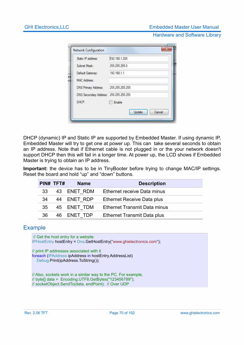
GHI Electronics,LLC Embedded Master User ManualHardware and Software Library
DHCP (dynamic) IP and Static IP are supported by Embedded Master. If using dynamic IP, Embedded Master will try to get one at power up. This can take several seconds to obtain an IP address. Note that if Ethernet cable is not plugged in or the your network doesn't support DHCP then this will fail in a longer time. At power up, the LCD shows if Embedded Master is trying to obtain an IP address.Important: the device has to be in TinyBooter before trying to change MAC/IP settings. Reset the board and hold “up” and “down” buttons.
PIN# TFT# Name Description33 43 ENET_RDM Ethernet receive Data minus34 44 ENET_RDP Ethernet Receive Data plus35 45 ENET_TDM Ethernet Transmit Data minus36 46 ENET_TDP Ethernet Transmit Data plus
Example// Get the host entry for a website
IPHostEntry hostEntry = Dns.GetHostEntry("www.ghielectronics.com");
// print IP addresses associated with it foreach (IPAddress ipAddress in hostEntry.AddressList) Debug.Print(ipAddress.ToString());
// Also, sockets work in a similar way to the PC. For example, // byte[] data = Encoding.UTF8.GetBytes("123456789"); // socketObject.SendTo(data, endPoint); // Over UDP
Rev. 2.06 TFT Page 70 of 102 www.ghielectronics.com
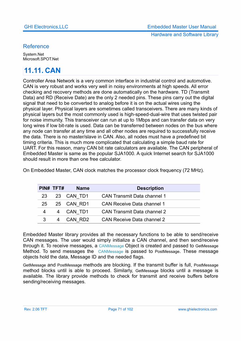
GHI Electronics,LLC Embedded Master User ManualHardware and Software Library
ReferenceSystem.NetMicrosoft.SPOT.Net
11.11. CANController Area Network is a very common interface in industrial control and automotive. CAN is very robust and works very well in noisy environments at high speeds. All error checking and recovery methods are done automatically on the hardware. TD (Transmit Data) and RD (Receive Date) are the only 2 needed pins. These pins carry out the digital signal that need to be converted to analog before it is on the actual wires using the physical layer. Physical layers are sometimes called transceivers. There are many kinds of physical layers but the most commonly used is high-speed-dual-wire that uses twisted pair for noise immunity. This transceiver can run at up to 1Mbps and can transfer data on very long wires if low bit-rate is used. Data can be transferred between nodes on the bus where any node can transfer at any time and all other nodes are required to successfully receive the data. There is no master/slave in CAN. Also, all nodes must have a predefined bit timing criteria. This is much more complicated that calculating a simple baud rate for UART. For this reason, many CAN bit rate calculators are available. The CAN peripheral of Embedded Master is same as the popular SJA1000. A quick Internet search for SJA1000 should result in more than one free calculator.
On Embedded Master, CAN clock matches the processor clock frequency (72 MHz).
PIN# TFT# Name Description23 23 CAN_TD1 CAN Transmit Data channel 125 25 CAN_RD1 CAN Receive Data channel 14 4 CAN_TD1 CAN Transmit Data channel 23 4 CAN_RD2 CAN Receive Data channel 2
Embedded Master library provides all the necessary functions to be able to send/receive CAN messages. The user would simply initialize a CAN channel, and then send/receive through it. To receive messages, a CANMessage Object is created and passed to GetMessage Method. To send messages the CANMessage is passed to PostMessage. These message objects hold the data, Message ID and the needed flags.GetMessage and PostMessage methods are blocking. If the transmit buffer is full, PostMessage method blocks until is able to proceed. Similarly, GetMessage blocks until a message is available. The library provide methods to check for transmit and receive buffers before sending/receiving messages.
Rev. 2.06 TFT Page 71 of 102 www.ghielectronics.com
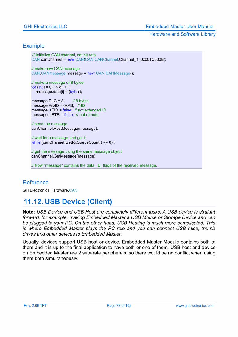
GHI Electronics,LLC Embedded Master User ManualHardware and Software Library
Example// Initialize CAN channel, set bit rate
CAN canChannel = new CAN(CAN.CANChannel.Channel_1, 0x001C000B);
// make new CAN message CAN.CANMessage message = new CAN.CANMessage();
// make a message of 8 bytes for (int i = 0; i < 8; i++) message.data[i] = (byte) i;
message.DLC = 8; // 8 bytes message.ArbID = 0xAB; // ID message.isEID = false; // not extended ID message.isRTR = false; // not remote
// send the message canChannel.PostMessage(message);
// wait for a message and get it. while (canChannel.GetRxQueueCount() == 0) ;
// get the message using the same message object canChannel.GetMessage(message); // Now "message" contains the data, ID, flags of the received message.
ReferenceGHIElectronics.Hardware.CAN
11.12. USB Device (Client)Note: USB Device and USB Host are completely different tasks. A USB device is straight forward, for example, making Embedded Master a USB Mouse or Storage Device and can be plugged to your PC. On the other hand, USB Hosting is much more complicated. This is where Embedded Master plays the PC role and you can connect USB mice, thumb drives and other devices to Embedded Master.Usually, devices support USB host or device. Embedded Master Module contains both of them and it is up to the final application to have both or one of them. USB host and device on Embedded Master are 2 separate peripherals, so there would be no conflict when using them both simultaneously.
Rev. 2.06 TFT Page 72 of 102 www.ghielectronics.com
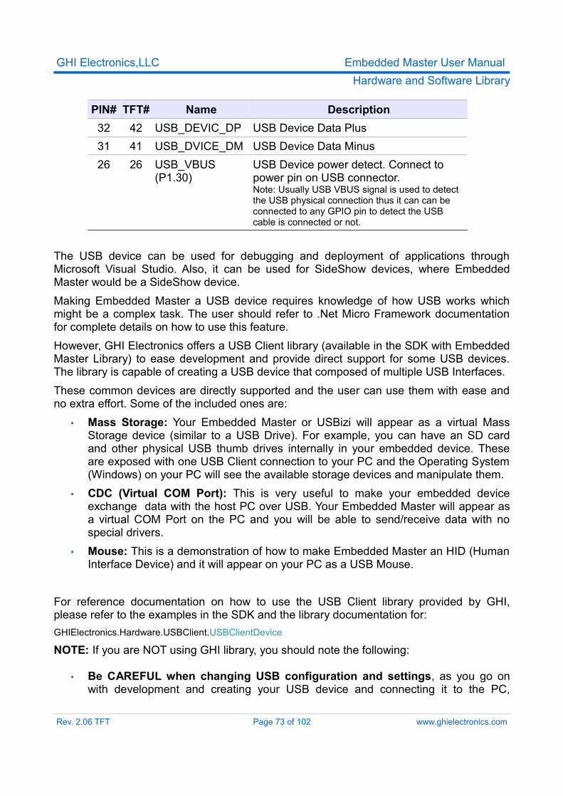
GHI Electronics,LLC Embedded Master User ManualHardware and Software Library
PIN# TFT# Name Description32 42 USB_DEVIC_DP USB Device Data Plus31 41 USB_DVICE_DM USB Device Data Minus26 26 USB_VBUS
(P1.30)USB Device power detect. Connect to power pin on USB connector.Note: Usually USB VBUS signal is used to detect the USB physical connection thus it can can be connected to any GPIO pin to detect the USB cable is connected or not.
The USB device can be used for debugging and deployment of applications through Microsoft Visual Studio. Also, it can be used for SideShow devices, where Embedded Master would be a SideShow device.Making Embedded Master a USB device requires knowledge of how USB works which might be a complex task. The user should refer to .Net Micro Framework documentation for complete details on how to use this feature.However, GHI Electronics offers a USB Client library (available in the SDK with Embedded Master Library) to ease development and provide direct support for some USB devices. The library is capable of creating a USB device that composed of multiple USB Interfaces.These common devices are directly supported and the user can use them with ease and no extra effort. Some of the included ones are:
• Mass Storage: Your Embedded Master or USBizi will appear as a virtual Mass Storage device (similar to a USB Drive). For example, you can have an SD card and other physical USB thumb drives internally in your embedded device. These are exposed with one USB Client connection to your PC and the Operating System (Windows) on your PC will see the available storage devices and manipulate them.
• CDC (Virtual COM Port): This is very useful to make your embedded device exchange data with the host PC over USB. Your Embedded Master will appear as a virtual COM Port on the PC and you will be able to send/receive data with no special drivers.
• Mouse: This is a demonstration of how to make Embedded Master an HID (Human Interface Device) and it will appear on your PC as a USB Mouse.
For reference documentation on how to use the USB Client library provided by GHI, please refer to the examples in the SDK and the library documentation for:GHIElectronics.Hardware.USBClient.USBClientDevice
NOTE: If you are NOT using GHI library, you should note the following:
• Be CAREFUL when changing USB configuration and settings, as you go on with development and creating your USB device and connecting it to the PC,
Rev. 2.06 TFT Page 73 of 102 www.ghielectronics.com
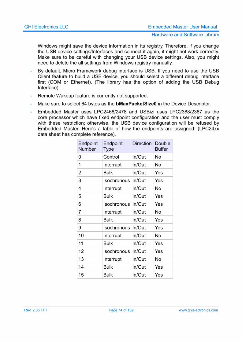
GHI Electronics,LLC Embedded Master User ManualHardware and Software Library
Windows might save the device information in its registry. Therefore, if you change the USB device settings/Interfaces and connect it again, it might not work correctly. Make sure to be careful with changing your USB device settings. Also, you might need to delete the all settings from Windows registry manually.
• By default, Micro Framework debug interface is USB. If you need to use the USB Client feature to build a USB device, you should select a different debug interface first (COM or Ethernet). (The library has the option of adding the USB Debug Interface).
• Remote Wakeup feature is currently not supported.• Make sure to select 64 bytes as the bMaxPacketSize0 in the Device Descriptor.• Embedded Master uses LPC2468/2478 and USBizi uses LPC2388/2387 as the
core processor which have fixed endpoint configuration and the user must comply with these restriction; otherwise, the USB device configuration will be refused by Embedded Master. Here's a table of how the endpoints are assigned: (LPC24xx data sheet has complete reference).
Endpoint Number
Endpoint Type
Direction Double Buffer
0 Control In/Out No1 Interrupt In/Out No2 Bulk In/Out Yes3 Isochronous In/Out Yes4 Interrupt In/Out No5 Bulk In/Out Yes6 Isochronous In/Out Yes7 Interrupt In/Out No8 Bulk In/Out Yes9 Isochronous In/Out Yes10 Interrupt In/Out No11 Bulk In/Out Yes12 Isochronous In/Out Yes13 Interrupt In/Out No14 Bulk In/Out Yes15 Bulk In/Out Yes
Rev. 2.06 TFT Page 74 of 102 www.ghielectronics.com
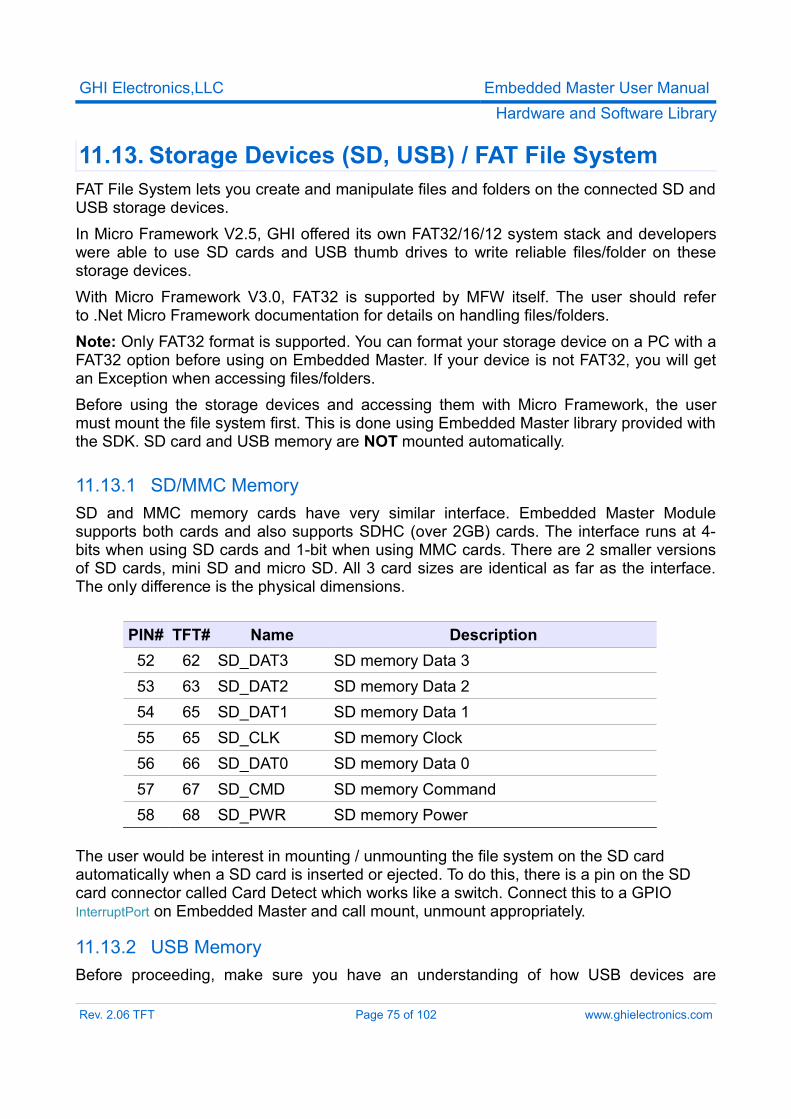
GHI Electronics,LLC Embedded Master User ManualHardware and Software Library
11.13. Storage Devices (SD, USB) / FAT File SystemFAT File System lets you create and manipulate files and folders on the connected SD and USB storage devices.In Micro Framework V2.5, GHI offered its own FAT32/16/12 system stack and developers were able to use SD cards and USB thumb drives to write reliable files/folder on these storage devices.With Micro Framework V3.0, FAT32 is supported by MFW itself. The user should refer to .Net Micro Framework documentation for details on handling files/folders.Note: Only FAT32 format is supported. You can format your storage device on a PC with a FAT32 option before using on Embedded Master. If your device is not FAT32, you will get an Exception when accessing files/folders.Before using the storage devices and accessing them with Micro Framework, the user must mount the file system first. This is done using Embedded Master library provided with the SDK. SD card and USB memory are NOT mounted automatically.
11.13.1 SD/MMC MemorySD and MMC memory cards have very similar interface. Embedded Master Module supports both cards and also supports SDHC (over 2GB) cards. The interface runs at 4-bits when using SD cards and 1-bit when using MMC cards. There are 2 smaller versions of SD cards, mini SD and micro SD. All 3 card sizes are identical as far as the interface. The only difference is the physical dimensions.
PIN# TFT# Name Description52 62 SD_DAT3 SD memory Data 353 63 SD_DAT2 SD memory Data 254 65 SD_DAT1 SD memory Data 155 65 SD_CLK SD memory Clock56 66 SD_DAT0 SD memory Data 057 67 SD_CMD SD memory Command58 68 SD_PWR SD memory Power
The user would be interest in mounting / unmounting the file system on the SD card automatically when a SD card is inserted or ejected. To do this, there is a pin on the SD card connector called Card Detect which works like a switch. Connect this to a GPIO InterruptPort on Embedded Master and call mount, unmount appropriately.
11.13.2 USB MemoryBefore proceeding, make sure you have an understanding of how USB devices are
Rev. 2.06 TFT Page 75 of 102 www.ghielectronics.com
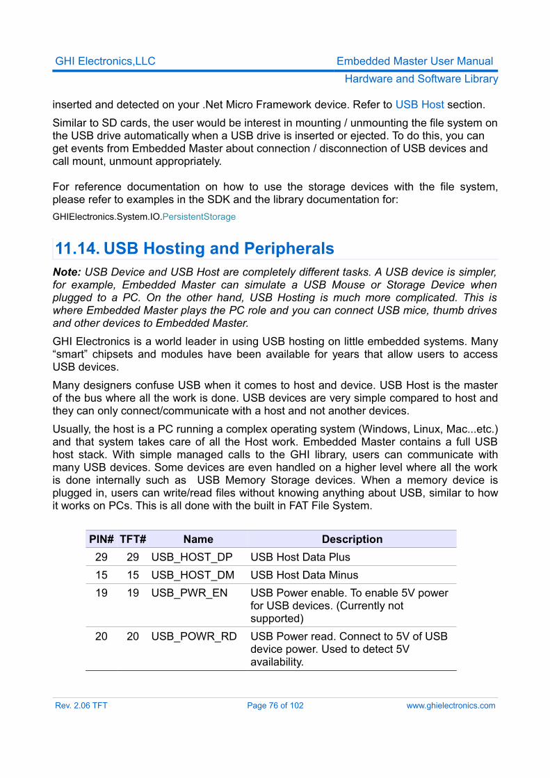
GHI Electronics,LLC Embedded Master User ManualHardware and Software Library
inserted and detected on your .Net Micro Framework device. Refer to USB Host section.Similar to SD cards, the user would be interest in mounting / unmounting the file system on the USB drive automatically when a USB drive is inserted or ejected. To do this, you can get events from Embedded Master about connection / disconnection of USB devices and call mount, unmount appropriately.
For reference documentation on how to use the storage devices with the file system, please refer to examples in the SDK and the library documentation for:GHIElectronics.System.IO.PersistentStorage
11.14. USB Hosting and PeripheralsNote: USB Device and USB Host are completely different tasks. A USB device is simpler, for example, Embedded Master can simulate a USB Mouse or Storage Device when plugged to a PC. On the other hand, USB Hosting is much more complicated. This is where Embedded Master plays the PC role and you can connect USB mice, thumb drives and other devices to Embedded Master.GHI Electronics is a world leader in using USB hosting on little embedded systems. Many “smart” chipsets and modules have been available for years that allow users to access USB devices.Many designers confuse USB when it comes to host and device. USB Host is the master of the bus where all the work is done. USB devices are very simple compared to host and they can only connect/communicate with a host and not another devices.Usually, the host is a PC running a complex operating system (Windows, Linux, Mac...etc.) and that system takes care of all the Host work. Embedded Master contains a full USB host stack. With simple managed calls to the GHI library, users can communicate with many USB devices. Some devices are even handled on a higher level where all the work is done internally such as USB Memory Storage devices. When a memory device is plugged in, users can write/read files without knowing anything about USB, similar to how it works on PCs. This is all done with the built in FAT File System.
PIN# TFT# Name Description29 29 USB_HOST_DP USB Host Data Plus15 15 USB_HOST_DM USB Host Data Minus19 19 USB_PWR_EN USB Power enable. To enable 5V power
for USB devices. (Currently not supported)
20 20 USB_POWR_RD USB Power read. Connect to 5V of USB device power. Used to detect 5V availability.
Rev. 2.06 TFT Page 76 of 102 www.ghielectronics.com
GHI Electronics,LLC Embedded Master User ManualHardware and Software Library
Notes: • Current implementation supports multiple devices but only one USB Hub can be
detected. A USB Hub has a maximum of 7 devices. Therefore, a USB Hub and seven USB devices can be used.
• Only supports one Interface per device (Several Interfaces might be present in a device).
• Device Connection/Disconnection events are sent per device and each device has a unique ID among the other connected devices.
• Self-Powered USB Hubs are highly recommended, Embedded Master and USBizi are not designed to deliver power for multiple USB devices.
• Some USB Hubs are built as two separate USB Hubs internally. For example, one USB Hub with seven ports is actually two Hubs inside. Therefore, Embedded Master will only detect one USB Hub with few ports.
Embedded Master library has a built in event system to handle connection/disconnection of devices. When a device is connected, an event is raised to the user and another event for disconnection when the device is removed. This event system is useful to dynamically check for the available devices. However, it is not a requirement. The user can, at any time, retrieve a list of the available devices and use some or all of them.
For an event driven system, the user registers to GHIElectronics.System.SystemManager.SystemEvent event.
To use USB Host you must start it first using (need to be called once):GHIElectronics.System.SystemManager.Start
After initialization, a list of current devices can be retrieved throughGHIElectronics.System.SystemManager.GetDevices
The list of devices is a GHIElectronics.System.SystemDevices.Device array. Each Device has a type and a unique ID. The type is simply the type of the device (Mouse, Printer, ...) and the ID is unique among the other current connected devices. The ID is useful if a user has two similar devices and needs to distinguish them, for example, two mice but each with a unique ID.
ExampleUsing the system with no events.
Rev. 2.06 TFT Page 77 of 102 www.ghielectronics.com
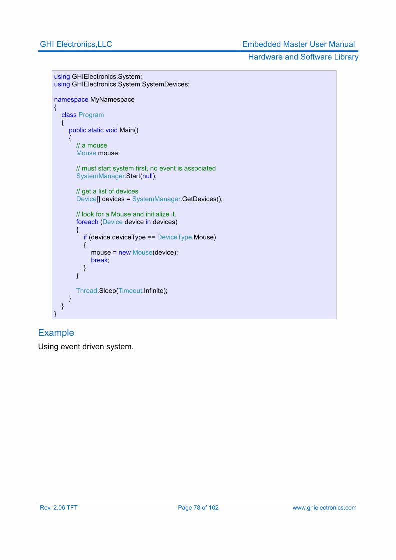
GHI Electronics,LLC Embedded Master User ManualHardware and Software Library
using GHIElectronics.System;using GHIElectronics.System.SystemDevices;
namespace MyNamespace{ class Program { public static void Main() { // a mouse Mouse mouse;
// must start system first, no event is associated SystemManager.Start(null);
// get a list of devices Device[] devices = SystemManager.GetDevices();
// look for a Mouse and initialize it. foreach (Device device in devices) { if (device.deviceType == DeviceType.Mouse) { mouse = new Mouse(device); break; } } Thread.Sleep(Timeout.Infinite); } }}
ExampleUsing event driven system.
Rev. 2.06 TFT Page 78 of 102 www.ghielectronics.com
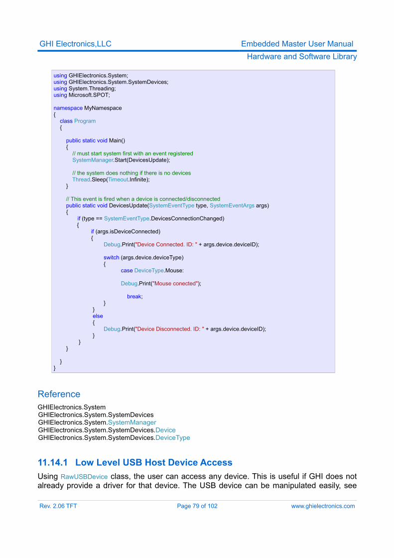
GHI Electronics,LLC Embedded Master User ManualHardware and Software Library
using GHIElectronics.System;using GHIElectronics.System.SystemDevices;using System.Threading;using Microsoft.SPOT;
namespace MyNamespace{ class Program {
public static void Main() { // must start system first with an event registered SystemManager.Start(DevicesUpdate);
// the system does nothing if there is no devices Thread.Sleep(Timeout.Infinite); }
// This event is fired when a device is connected/disconnected public static void DevicesUpdate(SystemEventType type, SystemEventArgs args) {
if (type == SystemEventType.DevicesConnectionChanged) { if (args.isDeviceConnected)
{ Debug.Print("Device Connected. ID: " + args.device.deviceID);
switch (args.device.deviceType) { case DeviceType.Mouse:
Debug.Print("Mouse conected");
break; } } else { Debug.Print("Device Disconnected. ID: " + args.device.deviceID); }
} }
}}
ReferenceGHIElectronics.System
GHIElectronics.System.SystemDevices GHIElectronics.System.SystemManager GHIElectronics.System.SystemDevices.Device GHIElectronics.System.SystemDevices.DeviceType
11.14.1 Low Level USB Host Device AccessUsing RawUSBDevice class, the user can access any device. This is useful if GHI does not already provide a driver for that device. The USB device can be manipulated easily, see
Rev. 2.06 TFT Page 79 of 102 www.ghielectronics.com
GHI Electronics,LLC Embedded Master User ManualHardware and Software Library
examples included in SDK.Note that you should have an understanding of the USB specifications in order to use this functionality (www.usb.org).
11.14.2 USB Mass Storage (Thumb Drive)USB memory devices are supported and work with Micro Framework file system, please refer to Storage Devices section for reference.
11.14.3 USB-To-Serial Device● USB-To-Serial FTDI● USB-To-Serial Prolific● USB-To-Serial SiLabs● USB-To-Serial Communication Device Class (CDC) modem● USB Sierra C885 3G modem
These devices can be connected to Embedded Master and are handled similar to physical COM ports. Some of them cannot be recognized by Embedded Master but you can still force Embedded Master to recognize them as in examples below. Also, there are two Prolific drivers for different versions of the hardware. If one of them does not work, you can force Embedded Master to use the other one.
ExampleConnecting a FTDI and SiLabs serial devices. Embedded Master recognized the FTDI but not the SiLabs one. Therefore, we will force Embedded Master to use the SiLabs driver.
Rev. 2.06 TFT Page 80 of 102 www.ghielectronics.com
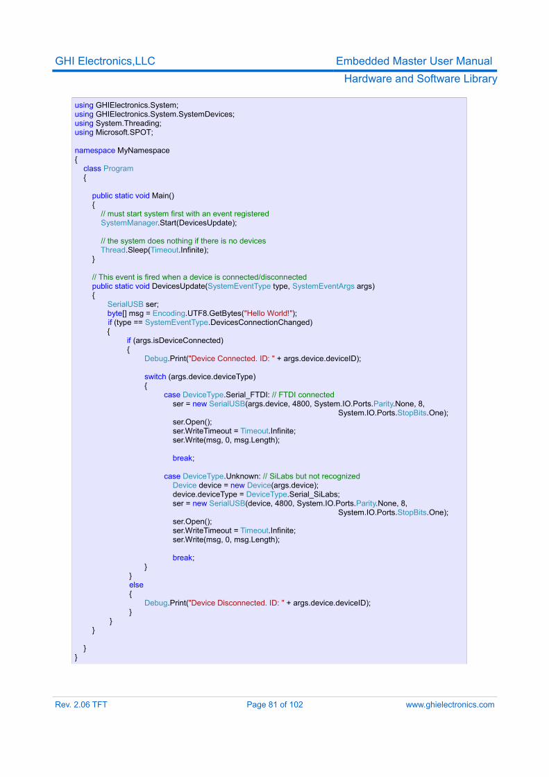
GHI Electronics,LLC Embedded Master User ManualHardware and Software Library
using GHIElectronics.System;using GHIElectronics.System.SystemDevices;using System.Threading;using Microsoft.SPOT;
namespace MyNamespace{ class Program {
public static void Main() { // must start system first with an event registered SystemManager.Start(DevicesUpdate);
// the system does nothing if there is no devices Thread.Sleep(Timeout.Infinite); }
// This event is fired when a device is connected/disconnected public static void DevicesUpdate(SystemEventType type, SystemEventArgs args) {
SerialUSB ser;byte[] msg = Encoding.UTF8.GetBytes("Hello World!");if (type == SystemEventType.DevicesConnectionChanged)
{ if (args.isDeviceConnected)
{ Debug.Print("Device Connected. ID: " + args.device.deviceID);
switch (args.device.deviceType) {
case DeviceType.Serial_FTDI: // FTDI connected ser = new SerialUSB(args.device, 4800, System.IO.Ports.Parity.None, 8, System.IO.Ports.StopBits.One); ser.Open(); ser.WriteTimeout = Timeout.Infinite; ser.Write(msg, 0, msg.Length);
break;
case DeviceType.Unknown: // SiLabs but not recognized Device device = new Device(args.device); device.deviceType = DeviceType.Serial_SiLabs;
ser = new SerialUSB(device, 4800, System.IO.Ports.Parity.None, 8, System.IO.Ports.StopBits.One);
ser.Open(); ser.WriteTimeout = Timeout.Infinite; ser.Write(msg, 0, msg.Length);
break; } } else { Debug.Print("Device Disconnected. ID: " + args.device.deviceID); }
} }
}}
Rev. 2.06 TFT Page 81 of 102 www.ghielectronics.com
GHI Electronics,LLC Embedded Master User ManualHardware and Software Library
11.14.4 USB MouseEmbedded Master has direct support for Mice. The user simply connects a USB mouse to the system. It is found by checking the connection status of system devices. Each connected Mouse holds information about the current pressed buttons and the current position.
ScalingFirst, the user has to set the scale of the mouse axes. This is the range of reported mouse movements as the user move the mouse around. For example, let us assume the user has a screen width of 128 pixels. So a setting a scale with a minimum of -64 and a maximum of +64 would be appropriate; A a fast mouse movement refers to change of 64 in the direction.Here's an example that sets X, Y and Mouse Wheel Movement to values appropriate to an LCD 128 by 64:mouse.SetScale(-64, +64, -32, +32, -512, +512);
PositionThe position can be obtained as a Delta Position (Relative) or as a Cursor associated with it (Absolute). The Delta Position changes with a range (min, max) that is the same as the scale used earlier. The user can associate a cursor with the mouse that updates automatically. Values taken by the X and Y position in a cursor are in a range specified by the user. For example, in the earlier example, LCD with width of 128, the user can specify a cursor to start at 0 and end at 128. With this model, the user is able to use two mice each moving with a specified cursor in a different region on the LCD.Getting a mouse position:mouse.Cursor
mouse.DeltaPosition
An example of setting cursor bounds for X, Y and Wheel position on a LCD 128 by 64:mouse.SetCursorBounds(0, 128, 0, 64, 0, 64);
ButtonsThe Mouse class contains definitions for the current state of Left, Right, Middle, Extended Button 1 and Extended Button 2.
EventsPosition of the mouse or the state of the buttons can be obtained at anytime. Any changes are sent by events to the user. Each event will have a reference to the originating mouse. Also, the EventArgs for a mouse button event contains which button is associated with the event.
Rev. 2.06 TFT Page 82 of 102 www.ghielectronics.com
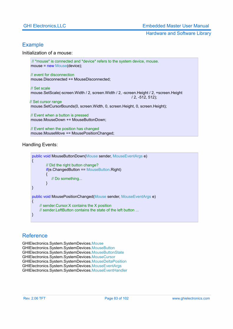
GHI Electronics,LLC Embedded Master User ManualHardware and Software Library
ExampleInitialization of a mouse:
// *mouse* is connected and *device* refers to the system device, mouse. mouse = new Mouse(device);
// event for disconnection mouse.Disconnected += MouseDisconnected;
// Set scale mouse.SetScale(-screen.Width / 2, screen.Width / 2, -screen.Height / 2, +screen.Height
/ 2, -512, 512); // Set cursor range mouse.SetCursorBounds(0, screen.Width, 0, screen.Height, 0, screen.Height);
// Event when a button is pressed mouse.MouseDown += MouseButtonDown;
// Event when the position has changed mouse.MouseMove += MousePositionChanged;
Handling Events:
public void MouseButtonDown(Mouse sender, MouseEventArgs e){
// Did the right button change?if(e.ChangedButton == MouseButton.Right){ // Do something...}
}
public void MousePositionChanged(Mouse sender, MouseEventArgs e){ // sender.Cursor.X contains the X position // sender.LeftButton contains the state of the left button ...}
ReferenceGHIElectronics.System.SystemDevices.MouseGHIElectronics.System.SystemDevices.MouseButtonGHIElectronics.System.SystemDevices.MouseButtonStateGHIElectronics.System.SystemDevices.MouseCursorGHIElectronics.System.SystemDevices.MouseDeltaPositionGHIElectronics.System.SystemDevices.MouseEventArgsGHIElectronics.System.SystemDevices.MouseEventHandler
Rev. 2.06 TFT Page 83 of 102 www.ghielectronics.com
GHI Electronics,LLC Embedded Master User ManualHardware and Software Library
11.14.5 USB KeyboardKeyboards are directly supported. They are found by checking the connection status of system devices.Keyboard LEDs are currently not supported.
Key EnumerationHolds definitions for all keys on a standard US-English keyboard.For example:Key.A // Refers to 'A'. Also 'a' is mapped to the same keyKey.F1 // Refers to F1 keyKey.D1 // Refers to the '1' key. Note this is also the '!'Key.Keypad_D1 // Refers to the '1' key on the keypad. Note this is also the 'End' key.
These definitions are useful for checking the pressed/released Keys. Events are also available that converts these definitions to an appropriate ASCII equivalent.
Current Key StateThe current state of any key can be obtained at anytime. For example,// Is LeftShift pressed?Keyboard.GetKeyState(Key.LeftShift);
EventsThe user can subscribe to different events when the keys are pressed/released using:Keyboard.KeyUp // Key releasedKeyboard.KeyDown // Key pressed
Two more events are available and are fired when the key can be mapped to an appropriate ASCII representation.Keyboard.CharDown // Key pressedKeyboard.CharUp // Key released
When an event occurs:Keyboard.Key // Refers to the Key associated with the event.Keyboard.KeyAscii // Refers to the ASCII representation of the pressed key, when
approperiate. Otherwise, this value is zero.
ExampleInitialization of a keyboard:
Rev. 2.06 TFT Page 84 of 102 www.ghielectronics.com
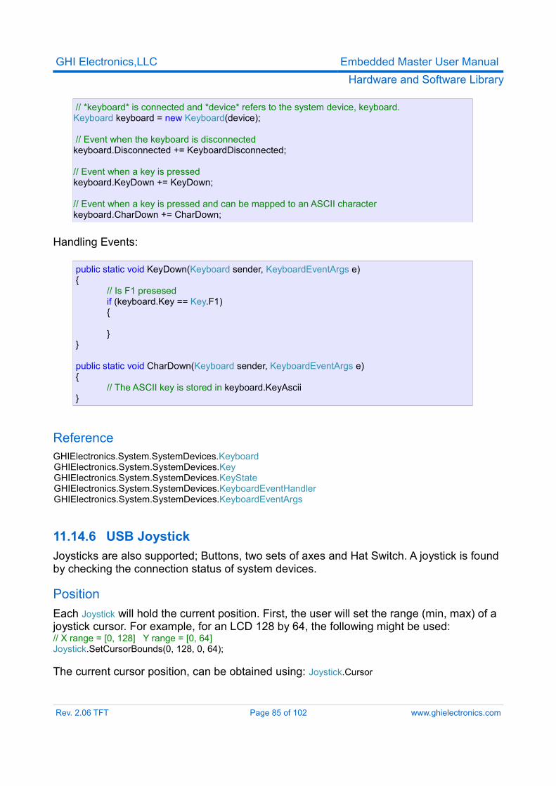
GHI Electronics,LLC Embedded Master User ManualHardware and Software Library
// *keyboard* is connected and *device* refers to the system device, keyboard. Keyboard keyboard = new Keyboard(device);
// Event when the keyboard is disconnected keyboard.Disconnected += KeyboardDisconnected; // Event when a key is pressed keyboard.KeyDown += KeyDown;
// Event when a key is pressed and can be mapped to an ASCII character keyboard.CharDown += CharDown;
Handling Events:
public static void KeyDown(Keyboard sender, KeyboardEventArgs e){ // Is F1 presesed if (keyboard.Key == Key.F1) { }}
public static void CharDown(Keyboard sender, KeyboardEventArgs e){ // The ASCII key is stored in keyboard.KeyAscii}
ReferenceGHIElectronics.System.SystemDevices.Keyboard
GHIElectronics.System.SystemDevices.Key GHIElectronics.System.SystemDevices.KeyState GHIElectronics.System.SystemDevices.KeyboardEventHandler GHIElectronics.System.SystemDevices.KeyboardEventArgs
11.14.6 USB JoystickJoysticks are also supported; Buttons, two sets of axes and Hat Switch. A joystick is found by checking the connection status of system devices.
PositionEach Joystick will hold the current position. First, the user will set the range (min, max) of a joystick cursor. For example, for an LCD 128 by 64, the following might be used:// X range = [0, 128] Y range = [0, 64]Joystick.SetCursorBounds(0, 128, 0, 64);
The current cursor position, can be obtained using: Joystick.Cursor
Rev. 2.06 TFT Page 85 of 102 www.ghielectronics.com
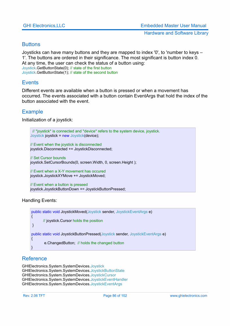
GHI Electronics,LLC Embedded Master User ManualHardware and Software Library
ButtonsJoysticks can have many buttons and they are mapped to index '0', to 'number to keys – 1'. The buttons are ordered in their significance. The most significant is button index 0.At any time, the user can check the status of a button using:Joystick.GetButtonState(0); // state of the first buttonJoystick.GetButtonState(1); // state of the second button
EventsDifferent events are available when a button is pressed or when a movement has occurred. The events associated with a button contain EventArgs that hold the index of the button associated with the event.
ExampleInitialization of a joystick:
// *joystick* is connected and *device* refers to the system device, joystick. Joystick joystick = new Joystick(device);
// Event when the joystick is disconnected joystick.Disconnected += JoystickDisconnected;
// Set Cursor bounds joystick.SetCursorBounds(0, screen.Width, 0, screen.Height );
// Event when a X-Y movement has occured joystick.JoystickXYMove += JoystickMoved;
// Event when a button is preseed joystick.JoystickButtonDown += JoystickButtonPressed;
Handling Events:
public static void JoystickMoved(Joystick sender, JoystickEventArgs e){ // joystick.Cursor holds the position }
public static void JoystickButtonPressed(Joystick sender, JoystickEventArgs e){ e.ChangedButton; // holds the changed button}
ReferenceGHIElectronics.System.SystemDevices.JoystickGHIElectronics.System.SystemDevices.JoystickButtonStateGHIElectronics.System.SystemDevices.JoystickCursorGHIElectronics.System.SystemDevices.JoystickEventHandlerGHIElectronics.System.SystemDevices.JoystickEventArgs
Rev. 2.06 TFT Page 86 of 102 www.ghielectronics.com
GHI Electronics,LLC Embedded Master User ManualHardware and Software Library
11.15. Miscellaneous Hardware AccessSeveral special access functions are available to the user to change some settings. For example, changing the used LCD type or debugging interface for .NET Micro Framework
Example Changing the used LCD
Misc.SetLCDType(Misc.LCDTypes.OSRAM_OS128064PK27MY);
ReferenceGHIElectronics.Hardware.Misc
11.16. System InformationSeveral system specific information can be obtained using the SystemInfo class. They contain the following:
➢ Serial Number: A unique serial number for your Embedded Master Module.➢ System Version Info: The installed firmware version.➢ Hardware Version: Embedded Master Module hardware version.➢ Extended Hardware Version: Special hardware for Embedded Master Module, for
example, CANxtra.
ExampleGetting the serial number.
string serialNumber = GHIElectronics.System.SystemInfo.SerialNumber;
ReferenceGHIElectronics.System.SystemInfo
Rev. 2.06 TFT Page 87 of 102 www.ghielectronics.com
GHI Electronics,LLC Embedded Master User ManualHardware and Software Library
11.17. Power Control / SleepHibernate is supported to save power. In this mode all clocks are stopped. This feature should be used by advanced users only. The user must disable peripherals such as USB Device and CAN before hibernating and re-enabling them after waking up, as needed. LPC24xx data sheet should be used as a reference.Hibernation mode is entered by calling Utility.HibernateSystem() then the processor will only wake up as the user specified. For example, in order to wake up on a button press connected to a GPIO pin, the pin must be defined as interrupt port and INTWAKE register must modified before sleeping. Likewise, registers can be directly modified to tweak the sleeping mode operation.Utility.HibernateSystem() first sleeps the processor (Power-down mode in PCON register, refer to LPC24xx datasheet), and after waking up, it resets all clocks including USBCLKCFG, then control is returned back to the user.Normal power operation is about 160mA. In hibernate mode, it is about 40mA.
Example// Before sleepingRegister INTWAKE = new Register(0xE01FC144); // Interrupt wakeupINTWAKE.Write((1 << 7) | (1 << 8)); // wake on GPIO0, GPIO2 activity
// define an interrupt pin to wake up the processor on the rising edge (on button release)InterruptPort DownBtn = new InterruptPort(EmbeddedMaster.Pins.E0x, true, Port.ResistorMode.PullUp,Port.InterruptMode.InterruptEdgeHigh);
// sleep, Press and release Down Button to wake it up. Microsoft.SPOT.Hardware.Utility.HibernateSystem();
// User can resume operation nowA full project example is provided with he SDK.Hibernate_GPIO_Wakeup and Hibernate_USB_Wakeup projects.
Rev. 2.06 TFT Page 88 of 102 www.ghielectronics.com
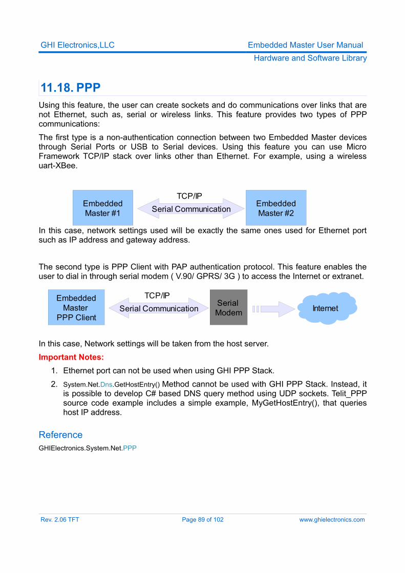
GHI Electronics,LLC Embedded Master User ManualHardware and Software Library
11.18. PPP Using this feature, the user can create sockets and do communications over links that are not Ethernet, such as, serial or wireless links. This feature provides two types of PPP communications:The first type is a non-authentication connection between two Embedded Master devices through Serial Ports or USB to Serial devices. Using this feature you can use Micro Framework TCP/IP stack over links other than Ethernet. For example, using a wireless uart-XBee.
In this case, network settings used will be exactly the same ones used for Ethernet port such as IP address and gateway address.
The second type is PPP Client with PAP authentication protocol. This feature enables the user to dial in through serial modem ( V.90/ GPRS/ 3G ) to access the Internet or extranet.
In this case, Network settings will be taken from the host server.Important Notes:
1. Ethernet port can not be used when using GHI PPP Stack.2. System.Net.Dns.GetHostEntry() Method cannot be used with GHI PPP Stack. Instead, it
is possible to develop C# based DNS query method using UDP sockets. Telit_PPP source code example includes a simple example, MyGetHostEntry(), that queries host IP address.
ReferenceGHIElectronics.System.Net.PPP
Rev. 2.06 TFT Page 89 of 102 www.ghielectronics.com
EmbeddedMaster #1
EmbeddedMaster #2Serial Communication
TCP/IP
InternetEmbedded
Master PPP Client
Serial ModemSerial Communication
TCP/IP
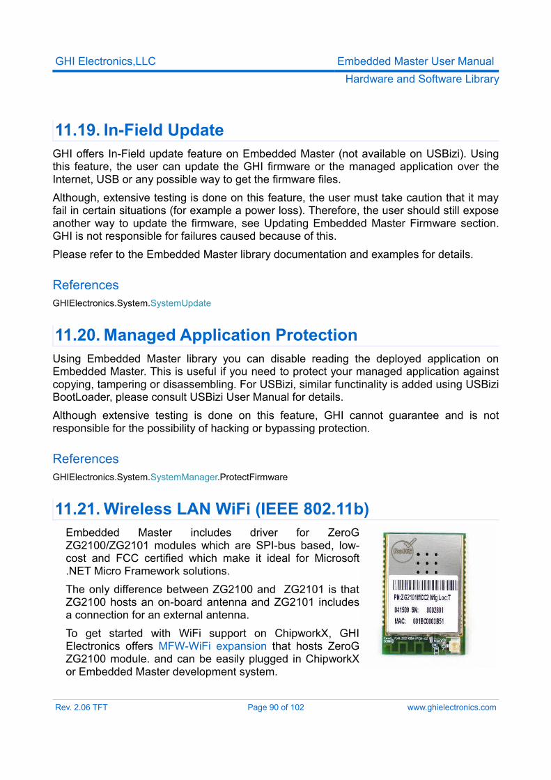
GHI Electronics,LLC Embedded Master User ManualHardware and Software Library
11.19. In-Field UpdateGHI offers In-Field update feature on Embedded Master (not available on USBizi). Using this feature, the user can update the GHI firmware or the managed application over the Internet, USB or any possible way to get the firmware files. Although, extensive testing is done on this feature, the user must take caution that it may fail in certain situations (for example a power loss). Therefore, the user should still expose another way to update the firmware, see Updating Embedded Master Firmware section. GHI is not responsible for failures caused because of this.Please refer to the Embedded Master library documentation and examples for details.
ReferencesGHIElectronics.System.SystemUpdate
11.20. Managed Application ProtectionUsing Embedded Master library you can disable reading the deployed application on Embedded Master. This is useful if you need to protect your managed application against copying, tampering or disassembling. For USBizi, similar functinality is added using USBizi BootLoader, please consult USBizi User Manual for details.Although extensive testing is done on this feature, GHI cannot guarantee and is not responsible for the possibility of hacking or bypassing protection.
ReferencesGHIElectronics.System.SystemManager.ProtectFirmware
11.21. Wireless LAN WiFi (IEEE 802.11b)Embedded Master includes driver for ZeroG ZG2100/ZG2101 modules which are SPI-bus based, low-cost and FCC certified which make it ideal for Microsoft .NET Micro Framework solutions.The only difference between ZG2100 and ZG2101 is that ZG2100 hosts an on-board antenna and ZG2101 includes a connection for an external antenna.To get started with WiFi support on ChipworkX, GHI Electronics offers MFW-WiFi expansion that hosts ZeroG ZG2100 module. and can be easily plugged in ChipworkX or Embedded Master development system.
Rev. 2.06 TFT Page 90 of 102 www.ghielectronics.com
GHI Electronics,LLC Embedded Master User ManualHardware and Software Library
GHI Electronics LLC is ZeroG authorized design partner:
http://www.zerogwireless.com/partners/partnersdevelop.htmlNote: currently more than one interface is not supported. the user must choose Ethernet or Wifi from managed code. the default interface is Ethernet.
References
GHIElectronics.System.Net.Interface
Rev. 2.06 TFT Page 91 of 102 www.ghielectronics.com
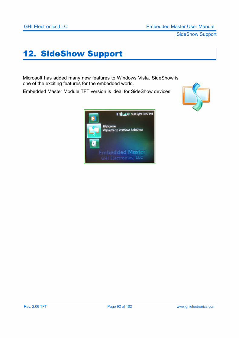
GHI Electronics,LLC Embedded Master User ManualSideShow Support
12. SideShow Support
Microsoft has added many new features to Windows Vista. SideShow is one of the exciting features for the embedded world. Embedded Master Module TFT version is ideal for SideShow devices.
Rev. 2.06 TFT Page 92 of 102 www.ghielectronics.com
GHI Electronics,LLC Embedded Master User ManualCustom Native Drivers
13. Custom Native Drivers
Managed code is safer for the system than native code. Programmers do not have to worry about memory leaks or uninitialized pointers anymore. These nice features come with a performance penalty. Depending on the application, speed may not be an issue.GHI Electronics has proven experience with customizing Micro Framework with extended functionality. FAT -previously- and USB libraries are completely written in native code but still accessible from managed applications. The same way, any required functionality can be added to the core of Embedded Master.
13.1. Requesting New Native DriverWhenever possible, it is recommended that the design is started with managed code. Once the driver is working then it would be easier to take the managed code and convert it to native code. For example, an application may require Embedded Master to transfer encrypted data over the network or CAN bus. We will also assume that required encryption is not supported by .NET Micro Framework. The encryption algorithm can be written in C# for testing the system. At this point, the developer can do some analysis to determine if the “bottleneck” is the encryption or not. GHI can now take the managed encryption algorithm and rewrite it in native code then add it to the core of Embedded Master for a fee. Please contact GHI for further details.
13.2. Required Native DriversSome drivers can't be developed in managed applications. The display is one of the devices that requires drivers to be written in native code and placed in the core. The driver even runs at power up before the managed system is ready yet. In this case, GHI can develop the complete driver or the user can supply some managed examples. LCDs on Embedded Master run on a dedicated SPI bus (SPI2). This second SPI bus can be used to connect the new unsupported LCD. A simple managed application can be used to reset and setup the new LCD. This simple managed application can be used as a base to start writing the native drivers.Important: User can access SPI2 but must be aware that it is used in the SPI-based Embedded Master LCD Driver when active.
13.3. Semi-Native DriversIn some case, a native driver can be used with minor modification from the managed side. Here is a scenario: A display need to be used. This display has the same controller as the
Rev. 2.06 TFT Page 93 of 102 www.ghielectronics.com
GHI Electronics,LLC Embedded Master User ManualCustom Native Drivers
one support by Embedded Master but it uses a different initialization settings. Or slower clock rate. The developer can use the GHI library to access the processor registers and re-initialize the display with correct settings and even change the SPI clock rate. This is also valid for TFT displays where a developer may need to change the timing characteristics of the TFT signals.
Rev. 2.06 TFT Page 94 of 102 www.ghielectronics.com
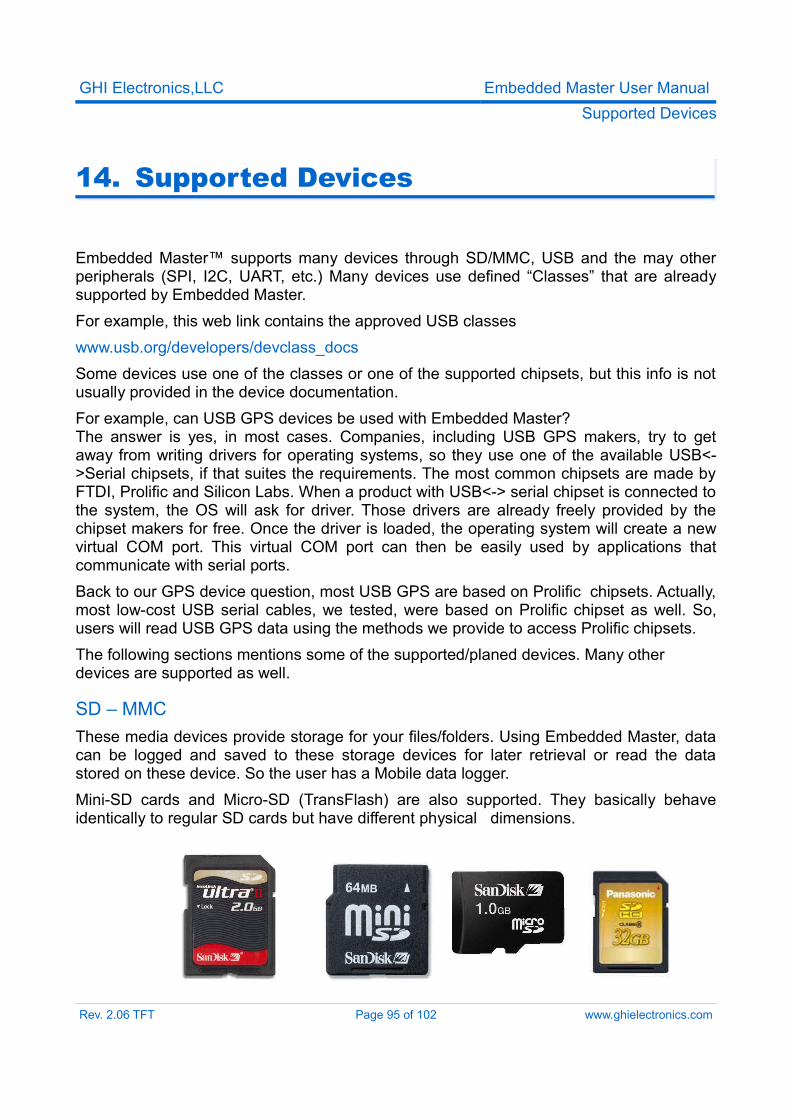
GHI Electronics,LLC Embedded Master User ManualSupported Devices
14. Supported Devices
Embedded Master™ supports many devices through SD/MMC, USB and the may other peripherals (SPI, I2C, UART, etc.) Many devices use defined “Classes” that are already supported by Embedded Master.For example, this web link contains the approved USB classeswww.usb.org/developers/devclass_docs Some devices use one of the classes or one of the supported chipsets, but this info is not usually provided in the device documentation.For example, can USB GPS devices be used with Embedded Master?The answer is yes, in most cases. Companies, including USB GPS makers, try to get away from writing drivers for operating systems, so they use one of the available USB<->Serial chipsets, if that suites the requirements. The most common chipsets are made by FTDI, Prolific and Silicon Labs. When a product with USB<-> serial chipset is connected to the system, the OS will ask for driver. Those drivers are already freely provided by the chipset makers for free. Once the driver is loaded, the operating system will create a new virtual COM port. This virtual COM port can then be easily used by applications that communicate with serial ports.Back to our GPS device question, most USB GPS are based on Prolific chipsets. Actually, most low-cost USB serial cables, we tested, were based on Prolific chipset as well. So, users will read USB GPS data using the methods we provide to access Prolific chipsets.The following sections mentions some of the supported/planed devices. Many other devices are supported as well.
SD – MMCThese media devices provide storage for your files/folders. Using Embedded Master, data can be logged and saved to these storage devices for later retrieval or read the data stored on these device. So the user has a Mobile data logger. Mini-SD cards and Micro-SD (TransFlash) are also supported. They basically behave identically to regular SD cards but have different physical dimensions.
Rev. 2.06 TFT Page 95 of 102 www.ghielectronics.com
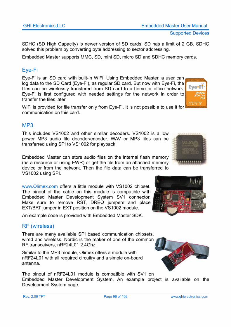
GHI Electronics,LLC Embedded Master User ManualSupported Devices
SDHC (SD High Capacity) is newer version of SD cards. SD has a limit of 2 GB. SDHC solved this problem by converting byte addressing to sector addressing.Embedded Master supports MMC, SD, mini SD, micro SD and SDHC memory cards.
Eye-FiEye-Fi is an SD card with built-in WiFi. Using Embedded Master, a user can log data to the SD Card (Eye-Fi), as regular SD card. But now with Eye-Fi, the files can be wirelessly transfered from SD card to a home or office network. Eye-Fi is first configured with needed settings for the network in order to transfer the files later.WiFi is provided for file transfer only from Eye-Fi. It is not possible to use it for communication on this card.
MP3This includes VS1002 and other similar decoders. VS1002 is a low power MP3 audio file decoder/encoder. WAV or MP3 files can be transferred using SPI to VS1002 for playback.
Embedded Master can store audio files on the internal flash memory (as a resource or using EWR) or get the file from an attached memory device or from the network. Then the file data can be transferred to VS1002 using SPI.
www.Olimex.com offers a little module with VS1002 chipset. The pinout of the cable on this module is compatible with Embedded Master Development System SV1 connector. Make sure to remove RST, DREQ jumpers and place EXT/BAT jumper in EXT position on the VS1002 module.An example code is provided with Embedded Master SDK.
RF (wireless)There are many available SPI based communication chipsets, wired and wireless. Nordic is the maker of one of the common RF transceivers, nRF24L01 2.4Ghz.Similar to the MP3 module, Olimex offers a module with nRF24L01 with all required circuitry and a simple on-board antenna.
The pinout of nRF24L01 module is compatible with SV1 on Embedded Master Development System. An example project is available on the Development System page.
Rev. 2.06 TFT Page 96 of 102 www.ghielectronics.com
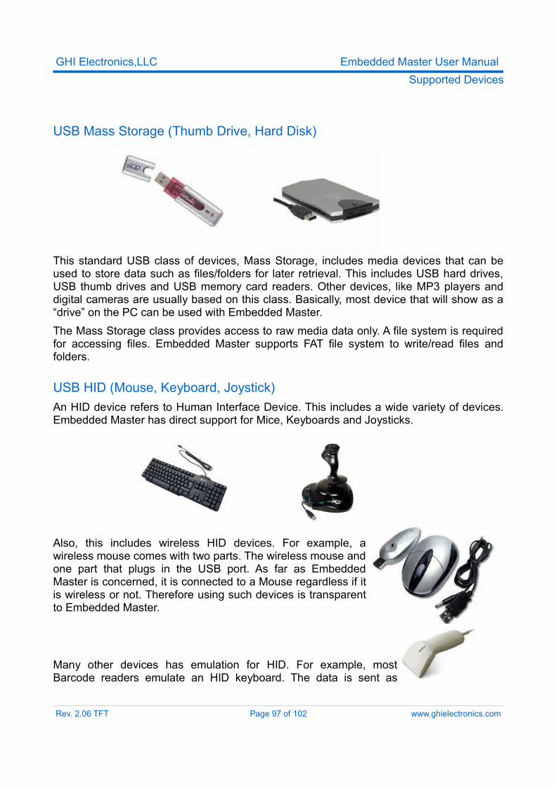
GHI Electronics,LLC Embedded Master User ManualSupported Devices
USB Mass Storage (Thumb Drive, Hard Disk)
This standard USB class of devices, Mass Storage, includes media devices that can be used to store data such as files/folders for later retrieval. This includes USB hard drives, USB thumb drives and USB memory card readers. Other devices, like MP3 players and digital cameras are usually based on this class. Basically, most device that will show as a “drive” on the PC can be used with Embedded Master.The Mass Storage class provides access to raw media data only. A file system is required for accessing files. Embedded Master supports FAT file system to write/read files and folders.
USB HID (Mouse, Keyboard, Joystick)An HID device refers to Human Interface Device. This includes a wide variety of devices. Embedded Master has direct support for Mice, Keyboards and Joysticks.
Also, this includes wireless HID devices. For example, a wireless mouse comes with two parts. The wireless mouse and one part that plugs in the USB port. As far as Embedded Master is concerned, it is connected to a Mouse regardless if it is wireless or not. Therefore using such devices is transparent to Embedded Master.
Many other devices has emulation for HID. For example, most Barcode readers emulate an HID keyboard. The data is sent as
Rev. 2.06 TFT Page 97 of 102 www.ghielectronics.com
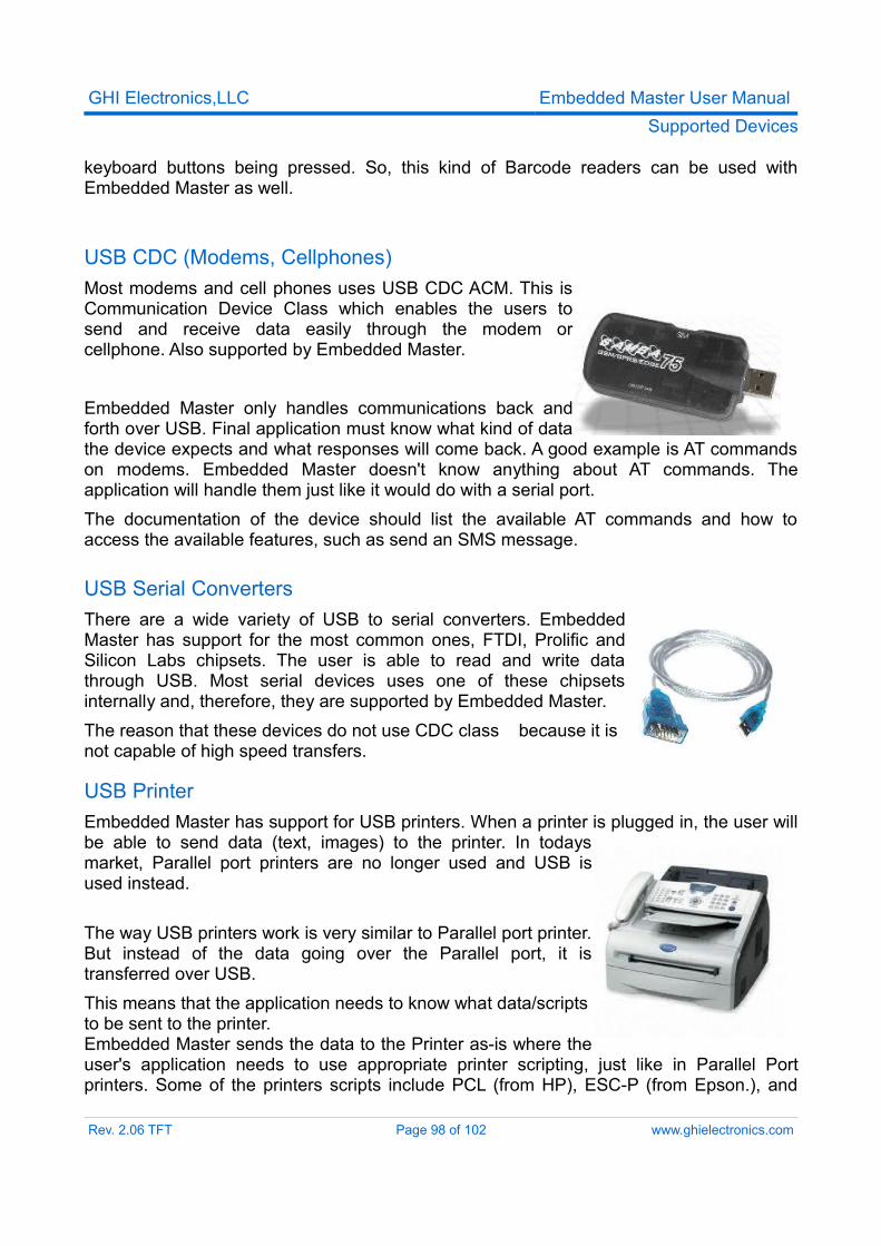
GHI Electronics,LLC Embedded Master User ManualSupported Devices
keyboard buttons being pressed. So, this kind of Barcode readers can be used with Embedded Master as well.
USB CDC (Modems, Cellphones)Most modems and cell phones uses USB CDC ACM. This is Communication Device Class which enables the users to send and receive data easily through the modem or cellphone. Also supported by Embedded Master.
Embedded Master only handles communications back and forth over USB. Final application must know what kind of data the device expects and what responses will come back. A good example is AT commands on modems. Embedded Master doesn't know anything about AT commands. The application will handle them just like it would do with a serial port.The documentation of the device should list the available AT commands and how to access the available features, such as send an SMS message.
USB Serial ConvertersThere are a wide variety of USB to serial converters. Embedded Master has support for the most common ones, FTDI, Prolific and Silicon Labs chipsets. The user is able to read and write data through USB. Most serial devices uses one of these chipsets internally and, therefore, they are supported by Embedded Master.The reason that these devices do not use CDC class because it is not capable of high speed transfers.
USB PrinterEmbedded Master has support for USB printers. When a printer is plugged in, the user will be able to send data (text, images) to the printer. In todays market, Parallel port printers are no longer used and USB is used instead.
The way USB printers work is very similar to Parallel port printer. But instead of the data going over the Parallel port, it is transferred over USB.This means that the application needs to know what data/scripts to be sent to the printer.Embedded Master sends the data to the Printer as-is where the user's application needs to use appropriate printer scripting, just like in Parallel Port printers. Some of the printers scripts include PCL (from HP), ESC-P (from Epson.), and
Rev. 2.06 TFT Page 98 of 102 www.ghielectronics.com
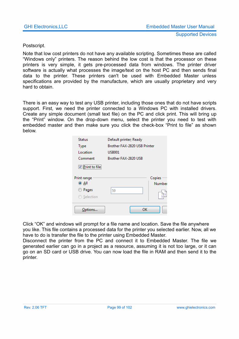
GHI Electronics,LLC Embedded Master User ManualSupported Devices
Postscript.Note that low cost printers do not have any available scripting. Sometimes these are called “Windows only” printers. The reason behind the low cost is that the processor on these printers is very simple, it gets pre-processed data from windows. The printer driver software is actually what processes the image/text on the host PC and then sends final data to the printer. These printers can't be used with Embedded Master unless specifications are provided by the manufacture, which are usually proprietary and very hard to obtain.
There is an easy way to test any USB printer, including those ones that do not have scripts support. First, we need the printer connected to a Windows PC with installed drivers. Create any simple document (small text file) on the PC and click print. This will bring up the “Print” window. On the drop-down menu, select the printer you need to test with embedded master and then make sure you click the check-box “Print to file” as shown below.
Click “OK” and windows will prompt for a file name and location. Save the file anywhere you like. This file contains a processed data for the printer you selected earlier. Now, all we have to do is transfer the file to the printer using Embedded Master.Disconnect the printer from the PC and connect it to Embedded Master. The file we generated earlier can go in a project as a resource, assuming it is not too large, or it can go on an SD card or USB drive. You can now load the file in RAM and then send it to the printer.
Rev. 2.06 TFT Page 99 of 102 www.ghielectronics.com
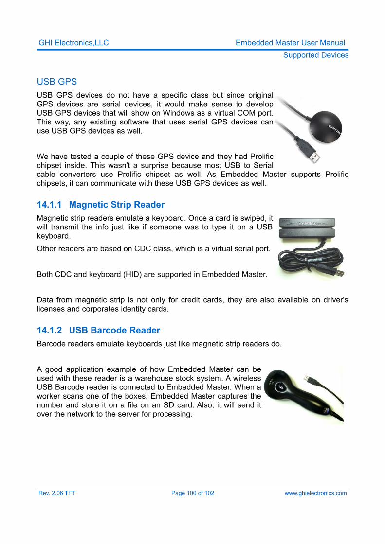
GHI Electronics,LLC Embedded Master User ManualSupported Devices
USB GPSUSB GPS devices do not have a specific class but since original GPS devices are serial devices, it would make sense to develop USB GPS devices that will show on Windows as a virtual COM port. This way, any existing software that uses serial GPS devices can use USB GPS devices as well.
We have tested a couple of these GPS device and they had Prolific chipset inside. This wasn't a surprise because most USB to Serial cable converters use Prolific chipset as well. As Embedded Master supports Prolific chipsets, it can communicate with these USB GPS devices as well.
14.1.1 Magnetic Strip ReaderMagnetic strip readers emulate a keyboard. Once a card is swiped, it will transmit the info just like if someone was to type it on a USB keyboard. Other readers are based on CDC class, which is a virtual serial port.
Both CDC and keyboard (HID) are supported in Embedded Master.
Data from magnetic strip is not only for credit cards, they are also available on driver's licenses and corporates identity cards.
14.1.2 USB Barcode ReaderBarcode readers emulate keyboards just like magnetic strip readers do.
A good application example of how Embedded Master can be used with these reader is a warehouse stock system. A wireless USB Barcode reader is connected to Embedded Master. When a worker scans one of the boxes, Embedded Master captures the number and store it on a file on an SD card. Also, it will send it over the network to the server for processing.
Rev. 2.06 TFT Page 100 of 102 www.ghielectronics.com
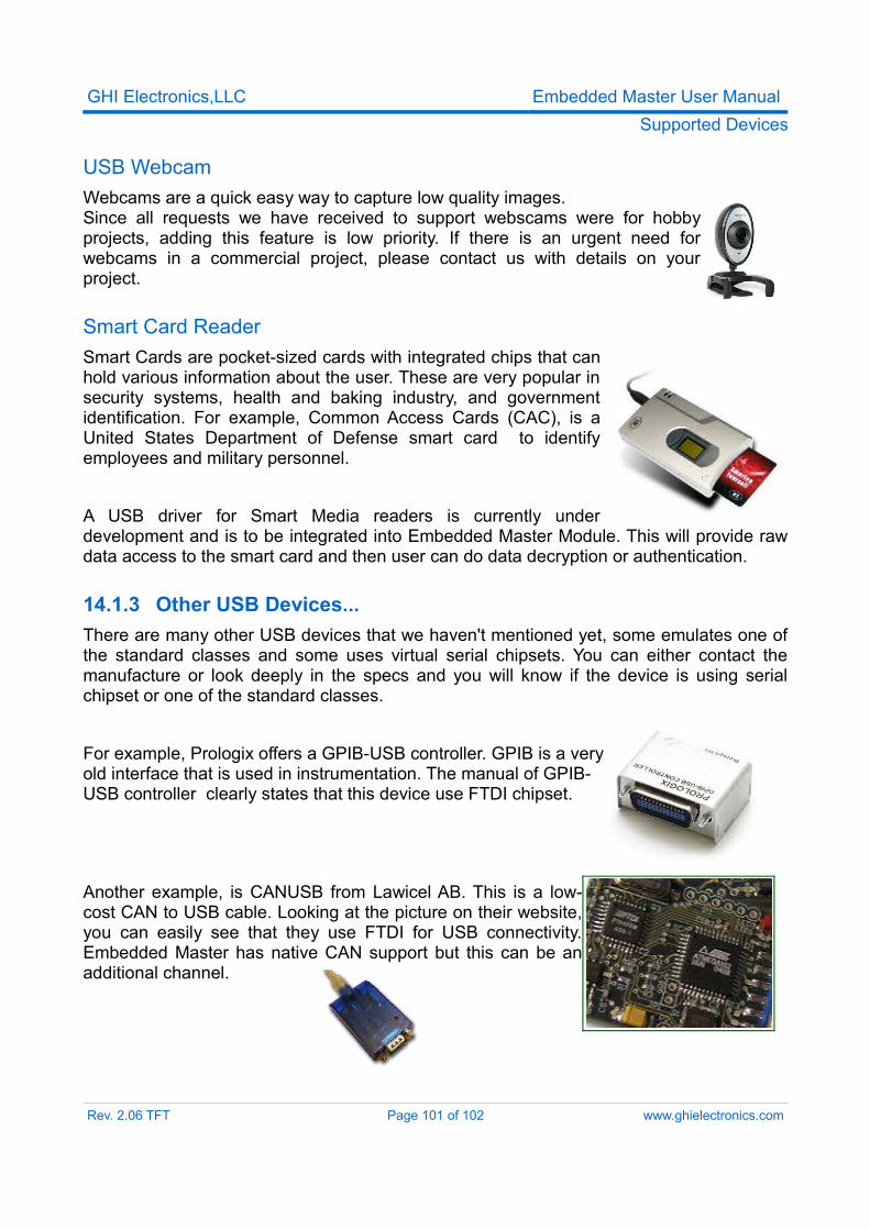
GHI Electronics,LLC Embedded Master User ManualSupported Devices
USB WebcamWebcams are a quick easy way to capture low quality images.Since all requests we have received to support webscams were for hobby projects, adding this feature is low priority. If there is an urgent need for webcams in a commercial project, please contact us with details on your project.
Smart Card ReaderSmart Cards are pocket-sized cards with integrated chips that can hold various information about the user. These are very popular in security systems, health and baking industry, and government identification. For example, Common Access Cards (CAC), is a United States Department of Defense smart card to identify employees and military personnel.
A USB driver for Smart Media readers is currently under development and is to be integrated into Embedded Master Module. This will provide raw data access to the smart card and then user can do data decryption or authentication.
14.1.3 Other USB Devices...There are many other USB devices that we haven't mentioned yet, some emulates one of the standard classes and some uses virtual serial chipsets. You can either contact the manufacture or look deeply in the specs and you will know if the device is using serial chipset or one of the standard classes.
For example, Prologix offers a GPIB-USB controller. GPIB is a very old interface that is used in instrumentation. The manual of GPIB-USB controller clearly states that this device use FTDI chipset.
Another example, is CANUSB from Lawicel AB. This is a low-cost CAN to USB cable. Looking at the picture on their website, you can easily see that they use FTDI for USB connectivity. Embedded Master has native CAN support but this can be an additional channel.
Rev. 2.06 TFT Page 101 of 102 www.ghielectronics.com
GHI Electronics,LLC Embedded Master User ManualAppendices
LicensingEmbedded Master module is fully licensed for commercial use. The module price covers the commercial use of Embedded Master Module with .Net Micro Framework and a licensed MAC address.
DisclaimerIN NO EVENT SHALL GHI ELECTRONICS, LLC. OR ITS CONTRIBUTORS BE LIABLE FOR ANY DIRECT, INDIRECT, INCIDENTAL, SPECIAL, EXEMPLARY, OR CONSEQUENTIAL DAMAGES (INCLUDING, BUT NOT LIMITED TO, PROCUREMENT OF SUBSTITUTE GOODS OR SERVICES; LOSS OF USE, DATA, OR PROFITS; OR BUSINESS INTERRUPTION) HOWEVER CAUSED AND ON ANY THEORY OF LIABILITY, WHETHER IN CONTRACT, STRICT LIABILITY, OR TORT (INCLUDING NEGLIGENCE OR OTHERWISE) ARISING IN ANY WAY OUT OF THE USE OF THIS SOFTWARE, EVEN IF ADVISED OF THE POSSIBILITY OF SUCH DAMAGE. SPECIFICATIONS ARE SUBJECT TO CHANGE WITHOUT ANY NOTICE. GHI ELECTRONICS, LLC LINE OF PRODUCTS ARE NOT DESIGNED FOR LIFE SUPPORT APPLICATIONS.
Embedded Master is a Trademark of GHI Electronics, LLC
.NET Micro Framework, Visual Studio, MFDeploy, Windows Vista, Windows SideShow are registered or unregistered trademarks of Microsoft Corporation.
Other Trademarks and Registered Trademarks are Owned by their Respective Companies.
Rev. 2.06 TFT Page 102 of 102 www.ghielectronics.com