Embed Size (px)
Citation preview

Embedded Ethernet Server foriSeries Monitor/Controller
Operator’s Manual
http://www.newportUS.com/iServer
®NEWPORT Electronics,Inc.

CountersFrequency Meters
PID ControllersClock/Timers
PrintersProcess Meters
On/OffControllersRecordersRelativeHumidity
TransmittersThermocouples
ThermistorsWire
Rate MetersTimers
TotalizersStrain Gauge
MetersVoltmetersMultimeters
Soldering IronTesterspH pens
pH ControllerspH Electrodes
RTDsThermowellsFlow Sensors
For Immediate AssistanceIn the U.S.A. and Canada: 1-800-NEWPORT®
In Mexico: (95) 800-NEWPORTSM
Or call your local NEWPORT Office.
Internet [email protected]
Additional products from
NEWPORTnetSM On-Line Servicewww.newportUS.com
® NEWPORT Electronics,Inc.
It is the policy of NEWPORT to comply with all worldwide safety and EMC/EMI regulations that apply. NEWPORT is constantlypursuing certification of its products to the European New Approach Directives. NEWPORT will add the CE mark to everyappropriate device upon certification.
The information contained in this document is believed to be correct but NEWPORT Electronics, Inc. accepts no liability for anyerrors it contains, and reserves the right to alter specifications without notice.
WARNING: These products are not designed for use in, and should not be used for, patient connected applications.
TRADEMARK NOTICE: , NEWPORT, NEWPORT® and newportUS.com are trademarks of NEWPORTElectronics, Inc.PATENT NOTICE: This product is covered by one or more of the following patents: U.S. Pat. No. Des. 336,895; 5,274,577/CANADA 2052599; 2052600/ ITALY 1249456; 1250938 / FRANCE BREVET No. 91 12756 / SPAIN 2039150; 2048066 / UKPATENT No. GB2 249 837; GB2 248 954 / GERMANY DE 41 34398 C2. The ™ is a Trademark of OMEGA Engineering, Inc.
Used Under License. Other US and International Patents pending or applied for.This device is marked with the international caution symbol. It is important to read the Setup Guide before installing orcommissioning this device as it contains important information relating to safety and EMC.

TABLE OF CONTENTS
Part 1: Introduction1.1 Safety and EMC Considerations ........................................................................21.2 Description ..........................................................................................................3
Part 2: Hardware2.1 Physical Characteristics and Mounting ...........................................................42.2 Rear Panel of iSeries Meter with Embedded Ethernet Server ........................42.3 DIP Switches on the iServer...............................................................................52.4 Serial Communication Interfaces (For Models with RS485 Port) ...................6
2.4.1 Wiring RS485 Interface ........................................................................72.5 Network Communication Interfaces .................................................................8
2.5.1 10Base-T RJ-45 Pinout .........................................................................82.5.2 10Base-T Crossover Wiring .................................................................8
Part 3: Network Configuration3.1 Network Protocols .............................................................................................93.2 Ethernet (MAC) Address ....................................................................................93.3 DHCP .............................................................................................................103.4 DNS .............................................................................................................103.5 IP Address .........................................................................................................11
3.5.1 Default IP Address ..............................................................................113.6 Port Number.......................................................................................................11
Part 4: Operations4.1 Serial Interface Configuration-Communication Protocol ..............................124.2 Command Structure..........................................................................................124.3 Command Formats ...........................................................................................124.4 Operations .........................................................................................................144.5 Setup and Operation using a Web Browser ..................................................14
4.5.1 Read Devices .....................................................................................164.5.1.1 Device Setpoints ................................................................................164.5.2 Send Raw Command ..........................................................................164.5.3 Device Setup .......................................................................................174.5.3.1 Modify Device Parameters (or Device List Entry) ............................174.5.4 Configuration ......................................................................................184.5.5 Access Control ..................................................................................21
4.6 Setting a New IP Address over the Network ..................................................234.7 Terminal Server Function ................................................................................244.8 Terminal Emulation ...........................................................................................254.9 Telnet Setup ......................................................................................................264.10 HTTPGET Program............................................................................................284.11 ARP Protocol .....................................................................................................294.12 Remote Access (Tunneling) .............................................................................30
4.12.1 Remote iServer ..................................................................................314.12.2 Local iServer ......................................................................................32
4.13 Mail Notifier Software .......................................................................................334.13.1 Installation ...........................................................................................334.13.2 Program Options Setup and Configuration ....................................344.13.3 Device Setting Setup and Configuration ..........................................35
Part 5: Specifications .................................................................................................................. 36Part 6: Factory Preset Values ......................................................................................................37Appendix A Glossary .............................................................................................................38Appendix B IP Address ........................................................................................................39Appendix C IP Netmask .........................................................................................................40Appendix D ASCII Chart .......................................................................................................41
ASCII Chart Control Codes .............................................................................42Part 7: Approvals Information
7.1 Electromagnetic Compatibility (EMC) ............................................................437.2 FCC ..............................................................................................................43
i
LIST OF FIGURES:
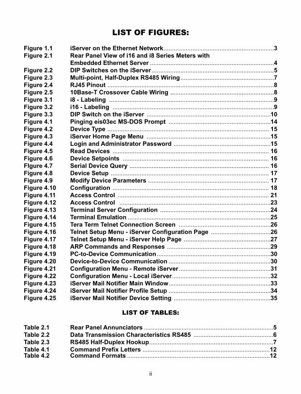
Figure 1.1 iServer on the Ethernet Network.................................................................3Figure 2.1 Rear Panel View of i16 and i8 Series Meters with
Embedded Ethernet Server .........................................................................4Figure 2.2 DIP Switches on the iServer ........................................................................5Figure 2.3 Multi-point, Half-Duplex RS485 Wiring .......................................................7Figure 2.4 RJ45 Pinout ..................................................................................................8Figure 2.5 10Base-T Crossover Cable Wiring .............................................................8Figure 3.1 i8 - Labeling .................................................................................................9Figure 3.2 i16 - Labeling ...............................................................................................9Figure 3.3 DIP Switch on the iServer .........................................................................10Figure 4.1 Pinging eis03ec MS-DOS Prompt ............................................................14Figure 4.2 Device Type ............................................................................................... 15Figure 4.3 iServer Home Page Menu .........................................................................15Figure 4.4 Login and Administrator Password .........................................................15Figure 4.5 Read Devices ............................................................................................ 16Figure 4.6 Device Setpoints ...................................................................................... 16FIgure 4.7 Serial Device Query .................................................................................. 16Figure 4.8 Device Setup ............................................................................................. 17Figure 4.9 Modify Device Parameters ....................................................................... 17Figure 4.10 Configuration ............................................................................................ 18Figure 4.11 Access Control ......................................................................................... 21Figure 4.12 Access Control .........................................................................................23Figure 4.13 Terminal Server Configuration .................................................................24Figure 4.14 Terminal Emulation ....................................................................................25Figure 4.15 Tera Term Telnet Connection Screen ......................................................26Figure 4.16 Telnet Setup Menu - iServer Configuration Page ...................................26Figure 4.17 Telnet Setup Menu - iServer Help Page ...................................................27Figure 4.18 ARP Commands and Responses .............................................................29Figure 4.19 PC-to-Device Communication ...................................................................30Figure 4.20 Device-to-Device Communication ............................................................30Figure 4.21 Configuration Menu - Remote iServer ......................................................31Figure 4.22 Configuration Menu - Local iServer..........................................................32Figure 4.23 iServer Mail Notifier Main Window............................................................33Figure 4.24 iServer Mail Notifier Profile Setup ............................................................34Figure 4.25 iServer Mail Notifier Device Setting .........................................................35
LIST OF TABLES:
Table 2.1 Rear Panel Annunciators ............................................................................5Table 2.2 Data Transmission Characteristics RS485 ...............................................6Table 2.3 RS485 Half-Duplex Hookup.........................................................................7Table 4.1 Command Prefix Letters ...........................................................................12Table 4.2 Command Formats ....................................................................................12
ii
NOTES, WARNINGS and CAUTIONS
Information that is especially important to note is identified by following labels:
• NOTE • WARNING or CAUTION• IMPORTANT• TIP
NOTE: Provides you with information that is important to successfullysetup and use the iServer.
CAUTION or WARNING: Tells you about the risk of electrical shock.
CAUTION, WARNING or IMPORTANT: Tells you of circumstances orpractices that can effect the instrument’s functionality and must referto accompanying documents.
TIP: Provides you helpful hints.
Before You Begin
Inspecting Your Shipment:
Remove the packing slip and verify that you have received everything listed. Inspect thecontainer and equipment for signs of damage as soon as you receive the shipment. Noteany evidence of rough handling in transit. Immediately report any damage to the shippingagent. The carrier will not honor damage claims unless all shipping material is saved forinspection. After examining and removing the contents, save the packing material andcarton in the event reshipment is necessary.
Customer Service:
If you need assistance, please contact the Customer Service Department nearest you.
Manuals, Software:
The latest Operation Manual as well as free iSeries configuration software and iServerMail Notifier are available at the website listed on the cover page of this manual oron the CD-ROM enclosed with your shipment.
1

PART 1INTRODUCTION
1.1 Safety and EMC Considerations
This device is marked with the international caution symbol. It is important toread this manual before installing or commissioning this device as it containsimportant information relating to Safety and EMC (ElectromagneticCompatibility).
This instrument is a panel mount device protected in accordance with EN 61010-1:2001, electrical safety requirements for electrical equipment for measurement,control and laboratory. Installation of this instrument should be done by qualifiedpersonnel. In order to ensure safe operation, the following instructions should befollowed.
This instrument has no power-on switch. An external switch or circuit-breakershall be included in the building installation as a disconnecting device. It shall bemarked to indicate this function, and it shall be in close proximity to theequipment within easy reach of the operator. The switch or circuit-breaker shallmeet the relevant requirements of IEC 947–1 and IEC 947-3 (InternationalElectrotechnical Commission). The switch shall not be incorporated in the mainsupply cord.
Furthermore, to provide protection against excessive energy being drawn fromthe main supply in case of a fault in the equipment, an overcurrent protectiondevice shall be installed.
• Do not exceed voltage rating on the label located on the top of theinstrument housing.
• Always disconnect power before changing signal and power connections.• Do not use this instrument on a work bench without its case for safety
reasons.• Do not operate this instrument in flammable or explosive atmospheres.• Do not expose this instrument to rain or moisture.• Unit mounting should allow for adequate ventilation to ensure instrument
does not exceed operating temperature rating.• Use electrical wires with adequate size to handle mechanical strain and
power requirements. Install without exposing bare wire outside the connectorto minimize electrical shock hazards.
EMC Considerations• Whenever EMC is an issue, always use shielded cables.• Never run signal and power wires in the same conduit.• Use signal wire connections with twisted-pair cables.• Install Ferrite Bead(s) on signal wires close to the instrument if EMC
problems persist.
Failure to follow all instructions and warnings may result in injury!
2
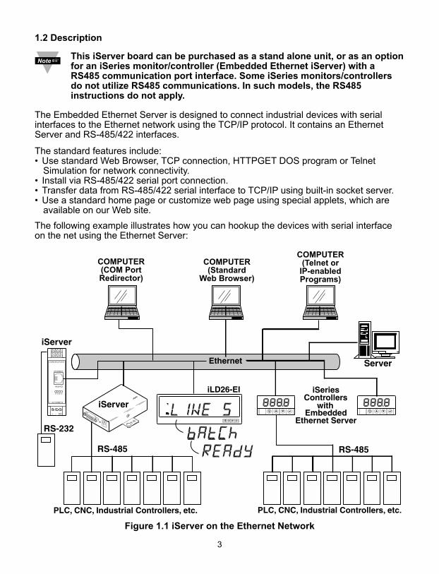
1.2 Description
This iServer board can be purchased as a stand alone unit, or as an optionfor an iSeries monitor/controller (Embedded Ethernet iServer) with aRS485 communication port interface. Some iSeries monitors/controllersdo not utilize RS485 communications. In such models, the RS485instructions do not apply.
The Embedded Ethernet Server is designed to connect industrial devices with serialinterfaces to the Ethernet network using the TCP/IP protocol. It contains an EthernetServer and RS-485/422 interfaces.
The standard features include:• Use standard Web Browser, TCP connection, HTTPGET DOS program or Telnet
Simulation for network connectivity.• Install via RS-485/422 serial port connection.• Transfer data from RS-485/422 serial interface to TCP/IP using built-in socket server.• Use a standard home page or customize web page using special applets, which are
available on our Web site.
The following example illustrates how you can hookup the devices with serial interfaceon the net using the Ethernet Server:
Figure 1.1 iServer on the Ethernet Network
COMMUNICATIONS
ETHERNET
DC POWER IN
RX TX ON COL
RESET
+ - N/C
COMPUTER(COM PortRedirector)
COMPUTER(Telnet or
IP-enabledPrograms)
COMPUTER(Standard
Web Browser)
3
4
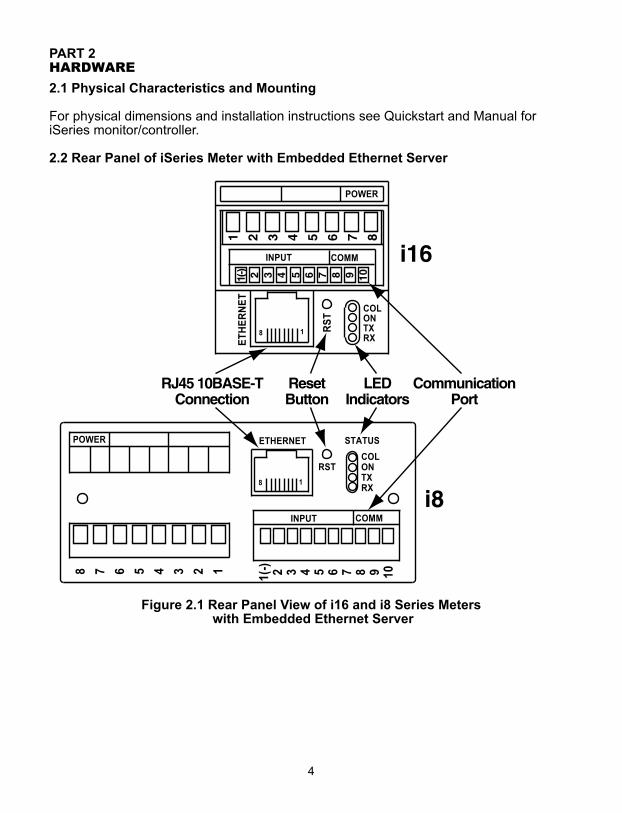
PART 2HARDWARE
2.1 Physical Characteristics and Mounting
For physical dimensions and installation instructions see Quickstart and Manual foriSeries monitor/controller.
2.2 Rear Panel of iSeries Meter with Embedded Ethernet Server
Figure 2.1 Rear Panel View of i16 and i8 Series Meterswith Embedded Ethernet Server
5
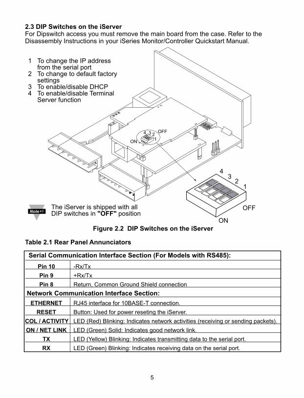
2.3 DIP Switches on the iServerFor Dipswitch access you must remove the main board from the case. Refer to theDisassembly Instructions in your iSeries Monitor/Controller Quickstart Manual.
Figure 2.2 DIP Switches on the iServer
Table 2.1 Rear Panel Annunciators
Serial Communication Interface Section (For Models with RS485):
Pin 10 -Rx/Tx
Pin 9 +Rx/Tx
Pin 8 Return, Common Ground Shield connection
Network Communication Interface Section:
ETHERNET RJ45 interface for 10BASE-T connection.
RESET Button: Used for power reseting the iServer.
COL / ACTIVITY LED (Red) Blinking: Indicates network activities (receiving or sending packets).
ON / NET LINK LED (Green) Solid: Indicates good network link.
TX LED (Yellow) Blinking: Indicates transmitting data to the serial port.
RX LED (Green) Blinking: Indicates receiving data on the serial port.
14 3 2
OFF
ON
1
43
2
OFF
ON
The iServer is shipped with allDIP switches in "OFF" position
1 To change the IP addressfrom the serial port
2 To change to default factorysettings
3 To enable/disable DHCP4 To enable/disable Terminal
Server function
6
2.4 Serial Communication Interfaces (For Models with RS485 Port)
The iSeries controller/monitor with the Embedded Ethernet Server option board supportonly RS485/422 interfaces. These standards define the electrical characteristics of acommunication network. The RS485 port of the Ethernet Server is fully compatible foruse with RS422 instruments. The RS485 is an extended version of the RS422communication standard which increases the allowable number of devices from 10 to32 by improving the electrical characteristics.
• The RS485 standard (multi-point) allows one or more devices (multi-dropped) to be connected to the Ethernet Server using a two-wire connection (half-duplex) +Rx/+Tx and –Rx/-Tx. Use of RS485 communications allows up to 32 devices to connect to theWeb Server with cable length up to 4000 feet long.
Although the RS485 is commonly referred to as a "two wire" connection, the Web Server also provides a ground/return shield connection to use as acommon connection for EMI noise protection.
Table 2.2 shows some characteristics of the RS485 communication interface.
Table 2.2 Data Transmission Characteristics RS485
Data Transmission Characteristics RS485Transmission Mode DifferentialElectrical connections 2 wireDrivers per line 32 driversReceivers per line 32 receiverMaximum data rate 10M bits/sMaximum cable length 4000 ft (1200 meters)
7
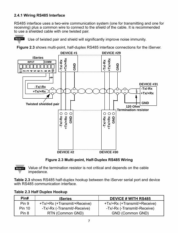
2.4.1 Wiring RS485 Interface
RS485 interface uses a two-wire communication system (one for transmitting and one forreceiving) plus a common wire to connect to the shield of the cable. It is recommendedto use a shielded cable with one twisted pair.
Use of twisted pair and shield will significantly improve noise immunity.
Figure 2.3 shows multi-point, half-duplex RS485 interface connections for the iServer.
Figure 2.3 Multi-point, Half-Duplex RS485 Wiring
Value of the termination resistor is not critical and depends on the cableimpedance.
Table 2.3 shows RS485 half-duplex hookup between the iServer serial port and devicewith RS485 communication interface.
Table 2.3 Half Duplex Hookup
Pin# iSeries DEVICE # WITH RS485Pin 9 +Tx/+Rx (+Transmit/+Receive) +Tx/+Rx (+Transmit/+Receive)
Pin 10 -Tx/-Rx (-Transmit/-Receive) -Tx/-Rx (-Transmit/-Receive)Pin 8 RTN (Common GND) GND (Common GND)
DEVICE #1 DEVICE #29
DEVICE #31
DEVICE #30DEVICE #2
120 OhmTermination resistor
GND
-Tx/-Rx+Tx/+Rx+Tx/+Rx
-Tx/-Rx
Twisted shielded pair
-Tx/
-Rx
-Tx/
-Rx
-Tx/
-Rx
-Tx/
-Rx
+Tx/
+Rx
+Tx/
+Rx
GN
D
GN
DG
ND
GN
D
+Tx/
+Rx
+Tx/
+Rx
.........................
.........................
...............................
...............................
iSeries
8
2.5 Network Communication Interfaces
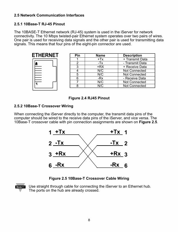
2.5.1 10Base-T RJ-45 Pinout
The 10BASE-T Ethernet network (RJ-45) system is used in the iServer for networkconnectivity. The 10 Mbps twisted-pair Ethernet system operates over two pairs of wires.One pair is used for receiving data signals and the other pair is used for transmitting datasignals. This means that four pins of the eight-pin connector are used.
Figure 2.4 RJ45 Pinout
2.5.2 10Base-T Crossover Wiring
When connecting the iServer directly to the computer, the transmit data pins of thecomputer should be wired to the receive data pins of the iServer, and vice versa. The10Base-T crossover cable with pin connection assignments are shown on Figure 2.5.
Figure 2.5 10Base-T Crossover Cable Wiring
Use straight through cable for connecting the iServer to an Ethernet hub. The ports on the hub are already crossed.
Pin Name Description1 +Tx + Transmit Data2 -Tx - Transmit Data3 +RX + Receive Data4 N/C Not Connected5 N/C Not Connected6 -Rx - Receive Data7 N/C Not Connected8 N/C Not Connected
9
PART 3NETWORK CONFIGURATION
3.1 Network Protocols
The iServer can be connected to the network using standard TCP/IP protocols. It alsosupports ARP, HTTP (WEB server), DHCP, DNS and Telnet protocols.
3.2 Ethernet (MAC) Address
MAC (Media Access Control) address is your computer's unique hardware number.When you're connected to the LAN from your computer, a correspondence table relatesyour IP address to your computer's physical (MAC) address. The MAC address can befound on the label of your device and contains 6 bytes (12 characters) of hexadecimalnumbers XX:XX:XX:XX:XX:XX hex
For example: 0A:0C:3D:0B:0A:0B
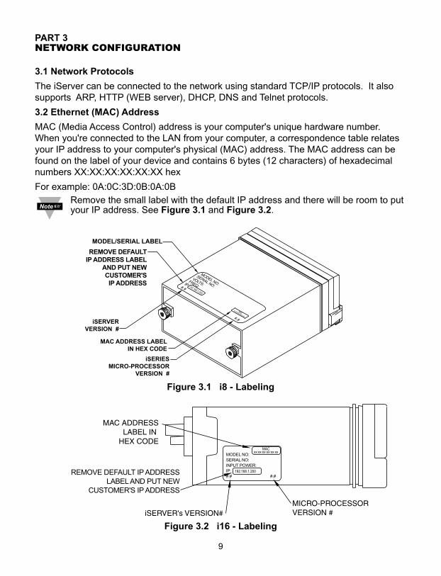
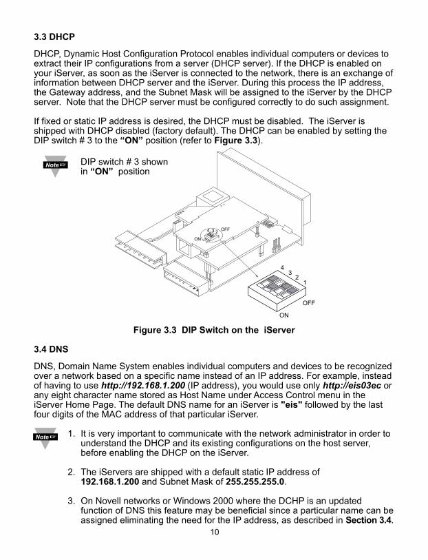
Remove the small label with the default IP address and there will be room to putyour IP address. See Figure 3.1 and Figure 3.2.
Figure 3.1 i8 - Labeling
Figure 3.2 i16 - Labeling
MODEL NO:SERIAL NO:INPUT POWER:IP:#.# #.#
3.3 DHCP
DHCP, Dynamic Host Configuration Protocol enables individual computers or devices toextract their IP configurations from a server (DHCP server). If the DHCP is enabled onyour iServer, as soon as the iServer is connected to the network, there is an exchange ofinformation between DHCP server and the iServer. During this process the IP address,the Gateway address, and the Subnet Mask will be assigned to the iServer by the DHCPserver. Note that the DHCP server must be configured correctly to do such assignment.
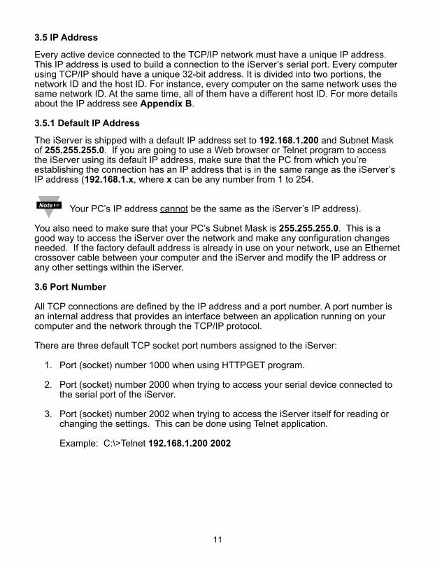
If fixed or static IP address is desired, the DHCP must be disabled. The iServer isshipped with DHCP disabled (factory default). The DHCP can be enabled by setting theDIP switch # 3 to the “ON” position (refer to Figure 3.3).
Figure 3.3 DIP Switch on the iServer
3.4 DNS
DNS, Domain Name System enables individual computers and devices to be recognizedover a network based on a specific name instead of an IP address. For example, insteadof having to use http://192.168.1.200 (IP address), you would use only http://eis03ec orany eight character name stored as Host Name under Access Control menu in theiServer Home Page. The default DNS name for an iServer is "eis" followed by the lastfour digits of the MAC address of that particular iServer.
1. It is very important to communicate with the network administrator in order tounderstand the DHCP and its existing configurations on the host server, before enabling the DHCP on the iServer.
2. The iServers are shipped with a default static IP address of 192.168.1.200 and Subnet Mask of 255.255.255.0.
3. On Novell networks or Windows 2000 where the DCHP is an updatedfunction of DNS this feature may be beneficial since a particular name can beassigned eliminating the need for the IP address, as described in Section 3.4.
1010
14 3 2
OFF
ON
1
43
2
OFF
ON
DIP switch # 3 shownin “ON” position
3.5 IP Address
Every active device connected to the TCP/IP network must have a unique IP address.This IP address is used to build a connection to the iServer’s serial port. Every computerusing TCP/IP should have a unique 32-bit address. It is divided into two portions, thenetwork ID and the host ID. For instance, every computer on the same network uses thesame network ID. At the same time, all of them have a different host ID. For more detailsabout the IP address see Appendix B.
3.5.1 Default IP Address
The iServer is shipped with a default IP address set to 192.168.1.200 and Subnet Maskof 255.255.255.0. If you are going to use a Web browser or Telnet program to accessthe iServer using its default IP address, make sure that the PC from which you’reestablishing the connection has an IP address that is in the same range as the iServer’sIP address (192.168.1.x, where x can be any number from 1 to 254.
Your PC’s IP address cannot be the same as the iServer’s IP address).
You also need to make sure that your PC’s Subnet Mask is 255.255.255.0. This is agood way to access the iServer over the network and make any configuration changesneeded. If the factory default address is already in use on your network, use an Ethernetcrossover cable between your computer and the iServer and modify the IP address orany other settings within the iServer.
3.6 Port Number
All TCP connections are defined by the IP address and a port number. A port number isan internal address that provides an interface between an application running on yourcomputer and the network through the TCP/IP protocol.
There are three default TCP socket port numbers assigned to the iServer:
1. Port (socket) number 1000 when using HTTPGET program.
2. Port (socket) number 2000 when trying to access your serial device connected to the serial port of the iServer.
3. Port (socket) number 2002 when trying to access the iServer itself for reading or changing the settings. This can be done using Telnet application.
Example: C:\>Telnet 192.168.1.200 2002
11
PART 4OPERATIONS
An industrial device with serial interfaces (PLC, CNC controllers, PC, Data DisplayDevices, etc.) can be connected to the serial port of the Web Server.
4.1 SERIAL INTERFACE CONFIGURATION - Communication Protocol
A data communication protocol defines the rules and structure of messages used by alldevices on a network for data exchange. A typical transaction will consist of a request tosend from the MASTER followed by the response from one or more SLAVE devices.Either a single (point-to-point) or multi-drop network (multi-point) is possible.
4.2 Command Structure
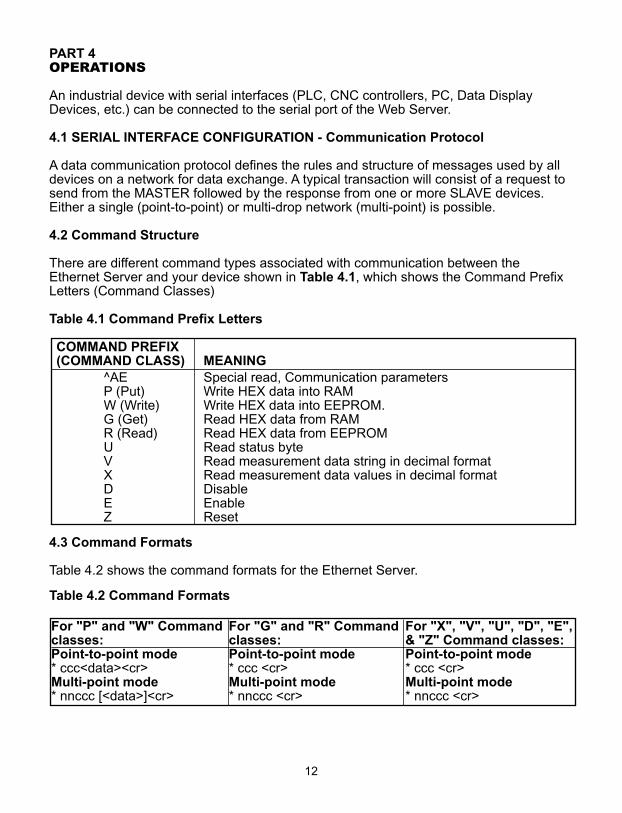
There are different command types associated with communication between theEthernet Server and your device shown in Table 4.1, which shows the Command PrefixLetters (Command Classes)
Table 4.1 Command Prefix Letters
COMMAND PREFIX (COMMAND CLASS) MEANING
^AE Special read, Communication parameters P (Put) Write HEX data into RAMW (Write) Write HEX data into EEPROM. G (Get) Read HEX data from RAMR (Read) Read HEX data from EEPROMU Read status byteV Read measurement data string in decimal formatX Read measurement data values in decimal formatD DisableE EnableZ Reset
4.3 Command Formats
Table 4.2 shows the command formats for the Ethernet Server.
Table 4.2 Command Formats
For "P" and "W" Command For "G" and "R" Command For "X", "V", "U", "D", "E",classes: classes: & "Z" Command classes:Point-to-point mode Point-to-point mode Point-to-point mode* ccc<data><cr> * ccc <cr> * ccc <cr>Multi-point mode Multi-point mode Multi-point mode* nnccc [<data>]<cr> * nnccc <cr> * nnccc <cr>
12
Where:
"*" is the selected Recognition Character. You may select any ASCII table symbol from"!" (HEX address "21") to the right-hand brace (HEX "7D") except for the caret "^", "A","E", which are reserved for bus format request.
"ccc" stands for the hex-ASCII Command Class letter (one of eleven given in Table 4.1),followed by the two hex-ASCII Command Suffix characters identifying the meter data,features, or menu items to which the command is directed.
"<data>" is the string of characters containing the variable information the computer issending to the meter. These data (whether BCD or binary) are encoded into hex-ASCIIcharacter (see Appendix D for binary-hex-ASCII chart), two characters to the byte.Square brackets [indicating optional status] enclose this string, since some commandscontain no data.
"<nn>" are the two ASCII characters for the device Bus Address of RS485 communication.Use values from "00" to hex "C7" (199 decimal).
The following format is used for each byte sent and received through serial port ofEthernet Server:
1. Seven or Eight-bit binary, Hexadecimal (0 ... 9, A ... F)
2. Two hexadecimal characters contained in each eight-bit field of the message
3. 1 start bit; 7 or 8 data bit; 1 Stop Bit; Odd, Even (No Parity) Bit
The figure below shows the bit sequences when a byte is transmitted or receivedthrough the Ethernet Server.
LSB MSB
LSB – Least Significant bit
MSB – Most Significant bit
Least Significant beat sent first
13
START 1 2 3 4 5 6 7 8 STOP PARITY
4.4 OPERATIONS
This iServer can be used and configured in several ways, depending on user’spreference and network setup. It can be used in Telnet simulation mode where itemmulates serial communication operation over a network cable or directly from a Webbrowser, like Netscape or Internet Explorer.
If DHCP and DNS servers are used, the connection is very simple, you do not need toworry about IP address, MAC address, or network conflicts, all of these issues are solvedfor you by your network DHCP and DNS server. All that is left for you to do, is to use astraight/normal network cable to connect the device to a hub and power it up. Then youcan go to your computer that is connected over the same network and from the MS-DOSPrompt window type "ping eisxxxx" followed by the last four digits from the MAC addresslocated on the side or back of the device.
Figure 4.1 Pinging eis03ec MS-DOS Prompt
This proves that the connection is proper and you can get into configuration or run modeusing the Telnet or Web browser.
4.5 Setup and Operation Using a Web Browsera) Start your web browser.
b) From the browser you type http://eisxxxx using the last four-digits from the MACaddress label located on the device if DHCP and DNS are used. If a static IP addressis used, then simly type http://x.x.x.x, where x.x.x.x is the iServer’s IP address.
c) The Home Page, shown below, will be displayed.
d) From the drop-down window you can select the type of device connected (iSeries,iDRN, iDRX, iR2, INFB, or iLD) then press Update to get to the Home Page.
C:\>ping eis03ecPinging eis03ec with 32 bytes of data:
Reply from eis03ec: bytes=32 time=15ms TTL=60Reply from eis03ec: bytes=32 time=8ms TTL=60Reply from eis03ec: bytes=32 time=8ms TTL=60Reply from eis03ec: bytes=32 time=8ms TTL=60
Pinging statistics for eis03ec: Packets: Sent=4, Received=4, Lost=0 (0% loss)
Approximate round trip times in milli-seconds:Minimum=8ms, Maximum=15ms, Average=9ms
14
15
4.5 Setup and Operation Using a Web Browser (continued)
Figure 4.2 Device Type
Figure 4.3 iServer Home Page Menu
In order to access certain menu items of the iServer Home Page, users may beprompted for a Login Password.
Figure 4.4 Login and Administrator Passwords
Login Password: This allows users to access and modify all of the iServer Home Pagemenu items, except “Access Control”, which requires an Administrator password (refer toSection 4.5.5). The “Read Devices” does not require a password.
The default Login password is 12345678. This password can be up to 16 alpha-numericcase-sensitive characters.
ADMINISTRATOR
ADMINISTRATOR
LOGIN
LOGIN
http://192.168.1.200 http://192.168.1.200
SERVER HOME PAGE
SERVER HOME PAGE
http://192.168.1.200Address
Read Devices
Device Setup
Configuration
Terminal Emulation
Serial Device Query
Access Control
iSERVER
iSERVER
http://192.168.1.200
Update Reset
Device Type Selection:
Firmware Version x.x
iSeries
iDRNiDRXiR2INF-BiLD
4.5.1 Read Devices
• Read variables from up to eight different devices.
• Read up to eight variables from the same device.
• Read and write the setpoint values to the device.
Figure 4.5 Read Devices
4.5.1.1 Device Setpoints
• When you click on Device No in the Read Device Page, you can edit the Setpoints.
Figure 4.6 Device Setpoints 4.5.2 Send Raw Command
• Send single command and receive response.
Figure 4.7 Serial Device Query
CommandResponse
*01 X01
01X01092.4
SERIAL DEVICE QUERY
http://192.168.1.200Address
Send
SERIAL DEVICE QUERY
DEVICE SETPOINTS
DEVICE SETPOINTS
http://192.168.1.200Address
Device No. (R01)
Main Menu
Setpoint #2: 0.
Setpoint #3: 0.
Setpoint #4: 0.
Setpoint #1: 0.
Update Reset
16
1. iSeries1 092.4 Deg.C
Auto Update
READ DEVICES
http://192.168.1.200Address
000
READ DEVICES
092.4 Deg. C
Main Menu
Click on Device No. on the left to query/change Device Setpoints
If you have 000, click the Auto Updatebutton to manually refresh the page.If you want to change the timeinterval of the page refresh, enter theamount of seconds in the box.
17
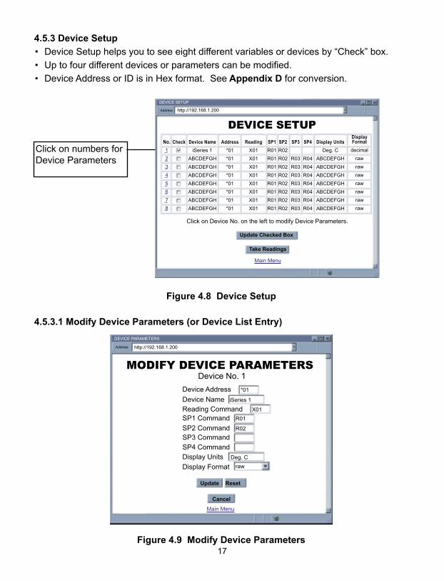
4.5.3 Device Setup
• Device Setup helps you to see eight different variables or devices by “Check” box.
• Up to four different devices or parameters can be modified.
• Device Address or ID is in Hex format. See Appendix D for conversion.
Figure 4.8 Device Setup
4.5.3.1 Modify Device Parameters (or Device List Entry)
Figure 4.9 Modify Device Parameters
MODIFY DEVICE PARAMETERS
DEVICE PARAMETERS
http://192.168.1.200Address
Device No. 1
Main Menu
Device Address *01
SP1 Command R01
SP2 Command R02
SP3 CommandSP4 CommandDisplay Units Deg. C
Display Format raw
Device Name iSeries 1
Reading Command X01
Update Reset
Cancel
DEVICE SETUP
DEVICE SETUP
http://192.168.1.200Address
Take Readings
Update Checked Box
Click on Device No. on the left to modify Device Parameters.
Main Menu
No.
1
2
3
4
5
6
7
8
Device Name
iSeries 1
ABCDEFGH
ABCDEFGH
ABCDEFGH
ABCDEFGH
ABCDEFGH
ABCDEFGH
ABCDEFGH
Display Units
Deg. C
ABCDEFGH
ABCDEFGH
ABCDEFGH
ABCDEFGH
ABCDEFGH
ABCDEFGH
ABCDEFGH
Address
*01
*01
*01
*01
*01
*01
*01
*01
Reading
X01
X01
X01
X01
X01
X01
X01
X01
SP1
R01
R01
R01
R01
R01
R01
R01
R01
SP2
R02
R02
R02
R02
R02
R02
R02
R02
SP3
R03
R03
R03
R03
R03
R03
R03
SP4
R04
R04
R04
R04
R04
R04
R04
DisplayFormat
decimal
raw
raw
raw
raw
raw
raw
raw
Check
Click on numbers forDevice Parameters
18
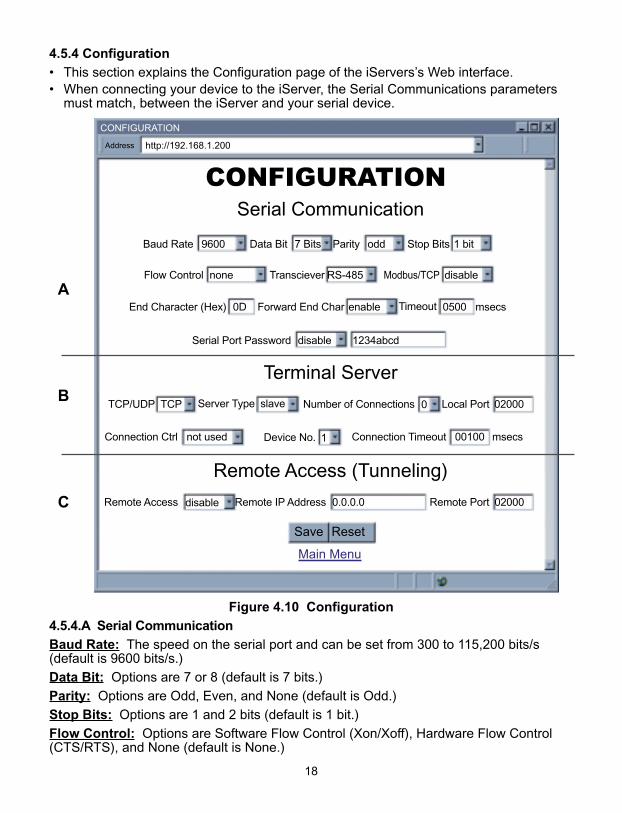
4.5.4 Configuration
• This section explains the Configuration page of the iServers’s Web interface.• When connecting your device to the iServer, the Serial Communications parameters
must match, between the iServer and your serial device.
Figure 4.10 Configuration
4.5.4.A Serial Communication
Baud Rate: The speed on the serial port and can be set from 300 to 115,200 bits/s(default is 9600 bits/s.)
Data Bit: Options are 7 or 8 (default is 7 bits.)
Parity: Options are Odd, Even, and None (default is Odd.)
Stop Bits: Options are 1 and 2 bits (default is 1 bit.)
Flow Control: Options are Software Flow Control (Xon/Xoff), Hardware Flow Control(CTS/RTS), and None (default is None.)
CONFIGURATION
CONFIGURATION
http://192.168.1.200Address
Serial Communication
Remote Access (Tunneling)
Terminal Server
Main Menu
Save Reset
Baud Rate 9600 Data Bit 7 Bits Parity odd Stop Bits 1 bit
Flow Control none Transciever RS-485 Modbus/TCP disable
End Character (Hex) 0D Forward End Char enable Timeout 0500 msecs
Serial Port Password disable 1234abcd
Connection Ctrl not used Device No. 1 Connection Timeout 00100 msecs
TCP/UDP TCP Server Type slave Number of Connections 0 Local Port 02000
Remote Access disable Remote IP Address 0.0.0.0 Remote Port 02000
A
B
C
4.5.4.A Serial Communication (continued)
Transceiver: Can either be set to RS-232 or two-wire RS-485 (default is RS-485.)
Modbus/TCP: A widely used protocol mainly in industrial automation applications with defaultTCP port number of 502 (see Local Port field). The options are Enable and Disable. If enabled,the Modbus/TCP is the only protocol driven by the iServer on its LAN port. If disabled, theTCP/IP is the only protocol driven by the iServer on its LAN port (default is disable).
End Character: When the defined Hex character is received by the iServer on its serialport, the iServer will forward the buffered serial data to the Ethernet. The default value is00, which forces the iServer to forward the data to the Ethernet as it receives the data onits serial port (this means that the iServer requires NO “end character” to forward the data).
Forward End Char: If enabled, the iServer will send the End Character out to theEthernet as part of the data. If disabled, the iServer will not count the End Character aspart of the data and will drop it (default is enabled.)
Timeout: In RS232 connection, if the iServer does not receive any more serial data withinthe given time value, the iServer will forward the buffered serial data to the Ethernet. Forexample, if the Timeout is set to 200 ms, the iServer will send out the buffered serial data tothe LAN, if it does not receive any more data on its serial port for a period of 200 ms.
In RS485 connection, the Timeout value is used to switch between serial transmit andreceive mode. Since the iServer supports 2-wire RS485, it needs to either transmit orreceive serial data and the Timeout value determines the time interval for each. Therange can be from 0 to 9999 ms (default is 500 ms).
4.5.4.B Terminal Server
TCP/UDP: The iServer supports TCP and UDP protocol (default is TCP). If UDP isselected, it can be configured either for Broadcast UDP or Directed UDP. In case ofBroadcast UDP, the iServer will transmit the serial data to every node on the network.This can be accomplished if the Remote IP Address is set to 255.255.255.255.
The Broadcast UDP is a practical solution when one device needs to communicate withmultiple PC’s or devices over the network (one-to-many connection). In the case ofdirected UDP, the iServer will transmit the serial data to a specific node on the network(one-to-one connection). This can be accomplished if the Remote IP Address is set tothe IP address of that specific node.
Server Type: In most cases the iServer will be acting as a Slave device. Slave option ischosen when a network host needs to connect to the serial port of the iServer (default is Slave)
Number of Connections: The range is from 0 to 5. If 0 is selected, the Terminal Serverfeature is disabled. That means that no network connection can be made to the serialport of the iServer. If 1 is selected, only one network connection can be made to theiServer’s serial port. Any number more than 1 would allow the network hosts to monitor(read only) the traffic on the iServer’s serial port simultaneously, but only one networkhost would be allowed to read and write (default is 0).
Local Port: This is the port or socket number for the iServer’s serial port. Any numberbetween 500 and 9999 can be defined with the exceptions of 1000 and 2002 which arealready used by the iServer for other purposes.
If the “Number of Connections” is set to 0, the iServer’s “Local Port” will be 1000,regardless of the displayed value inside the “Local Port” box. Once the “Numberof Connections” is changed to a non-zero number (1 - 5) the “Local Port” value willbe what is inside the box, this value by default indicates 2000 and is changable.
19
4.5.4.B Terminal Server (continued)
Connection Control: Some serial devices accept connections or disconnectconnections based on certain signal conditions. For example, a serial device may accepta connection only if the incoming DTR signal (connected to device’s DSR or DCD) ishigh or low. In this case, when the iServer receives the TCP connection, before itforwards it to its serial port, it must raise its DTR (DTR+) or to lower its DTR (DTR-). TheiServer is capable of doing this with any of the hardware or modem control signals (DTR,DSR, DCD, RTS, and CTS).
"Reconnect" is one of the options in the Connection Control menu. This optioncan be used in the Serial Tunneling described in Section 4.11. If the connectionin Serial Tunneling is broken due to network problems, power failure, etc., theReconnect option will try to get the connection back on line every whatever the"Connection Timeout" is set to. For Example, if the Connection Timeout is set to1000 x10 ms or 10 seconds, then every 10 seconds the iServer attempts toreconnect and reestablish the serial tunnel to the other network node.
Device No.: Refer to Section 4.5.1
4.5.4C Remote Access: This option needs to be enabled when Serial Tunneling isconfigured. The Serial Tunneling is explained in detail in Section 4.11.
Changes made in the iServer’s Configuration page can be saved permanentlyby pressing the Save button. Pressing the Reset button will set all the fieldsback to their default values.
20
21
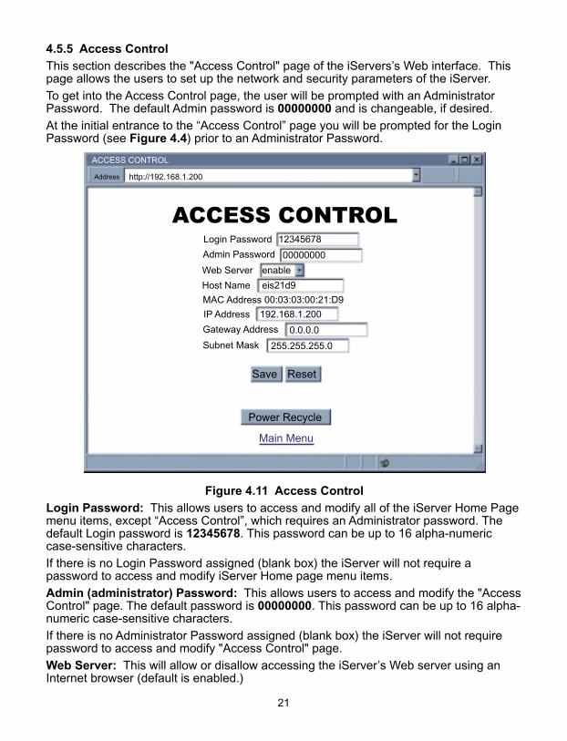
4.5.5 Access Control
This section describes the "Access Control" page of the iServers’s Web interface. Thispage allows the users to set up the network and security parameters of the iServer.
To get into the Access Control page, the user will be prompted with an AdministratorPassword. The default Admin password is 00000000 and is changeable, if desired.
At the initial entrance to the “Access Control” page you will be prompted for the LoginPassword (see Figure 4.4) prior to an Administrator Password.
Figure 4.11 Access Control
Login Password: This allows users to access and modify all of the iServer Home Pagemenu items, except “Access Control”, which requires an Administrator password. Thedefault Login password is 12345678. This password can be up to 16 alpha-numericcase-sensitive characters.
If there is no Login Password assigned (blank box) the iServer will not require apassword to access and modify iServer Home page menu items.
Admin (administrator) Password: This allows users to access and modify the "AccessControl" page. The default password is 00000000. This password can be up to 16 alpha-numeric case-sensitive characters.
If there is no Administrator Password assigned (blank box) the iServer will not requirepassword to access and modify "Access Control" page.
Web Server: This will allow or disallow accessing the iServer’s Web server using anInternet browser (default is enabled.)
ACCESS CONTROL
ACCESS CONTROL
http://192.168.1.200Address
Main Menu
Login Password 12345678
Admin Password 00000000
IP Address 192.168.1.200
Gateway Address 0.0.0.0
Subnet Mask 255.255.255.0
MAC Address 00:03:03:00:21:D9
Web Server enable
Host Name eis21d9
Save Reset
Power Recycle
4.5.5 Access Control (continued)
Host Name: Refer to Section 3.4, DNS.
MAC Address: This is also called Hardware address or Ethernet address, which isassigned to the iServer at production. The MAC (Media Access Control) address is theiServer’s unique hardware number and is not changeable.
IP Address: The IP (Internet Protocol) address is a 32-bit number that identifies eachsender or receiver of information that is sent in packets across the Ethernet or theInternet. The iServer’s default IP address is 192.168.1.200. The iServer’s IP addressshould be changed to fit user’s networking environment. Consult with your IT departmentfor obtaining an IP address.
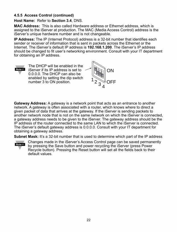
The DHCP will be enabled in theiServer if its IP address is set to0.0.0.0. The DHCP can also beenabled by setting the dip switchnumber 3 to ON position.
Gateway Address: A gateway is a network point that acts as an entrance to anothernetwork. A gateway is often associated with a router, which knows where to direct agiven packet of data that arrives at the gateway. If the iServer is sending packets toanother network node that is not on the same network on which the iServer is connected,a gateway address needs to be given to the iServer. The gateway address should be theIP address of the router connected to the same LAN to which the iServer is connected.The iServer’s default gateway address is 0.0.0.0. Consult with your IT department forobtaining a gateway address.
Subnet Mask: It’s a 32-bit number that is used to determine which part of the IP address
Changes made in the iServer’s Access Control page can be saved permanentlyby pressing the Save button and power recycling the iServer (press PowerRecycle button). Pressing the Reset button will set all the fields back to theirdefault values.
22
1
432 OFF
ON
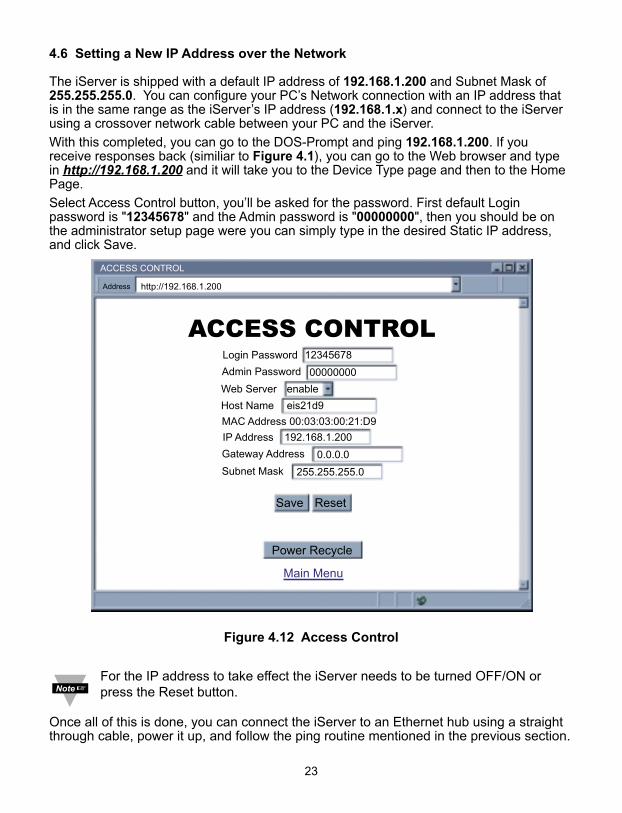
4.6 Setting a New IP Address over the Network
The iServer is shipped with a default IP address of 192.168.1.200 and Subnet Mask of255.255.255.0. You can configure your PC’s Network connection with an IP address thatis in the same range as the iServer’s IP address (192.168.1.x) and connect to the iServerusing a crossover network cable between your PC and the iServer.
With this completed, you can go to the DOS-Prompt and ping 192.168.1.200. If youreceive responses back (similiar to Figure 4.1), you can go to the Web browser and typein http://192.168.1.200 and it will take you to the Device Type page and then to the HomePage.
Select Access Control button, you’ll be asked for the password. First default Loginpassword is "12345678" and the Admin password is "00000000", then you should be onthe administrator setup page were you can simply type in the desired Static IP address,and click Save.
Figure 4.12 Access Control
For the IP address to take effect the iServer needs to be turned OFF/ON orpress the Reset button.
Once all of this is done, you can connect the iServer to an Ethernet hub using a straightthrough cable, power it up, and follow the ping routine mentioned in the previous section.
ACCESS CONTROL
ACCESS CONTROL
http://192.168.1.200Address
Main Menu
Login Password 12345678
Admin Password 00000000
IP Address 192.168.1.200
Gateway Address 0.0.0.0
Subnet Mask 255.255.255.0
MAC Address 00:03:03:00:21:D9
Web Server enable
Host Name eis21d9
Save Reset
Power Recycle
23
24
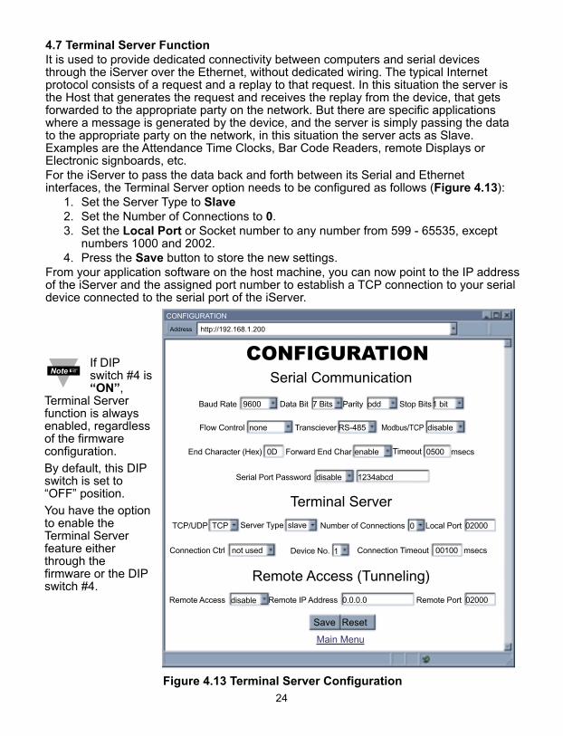
4.7 Terminal Server FunctionIt is used to provide dedicated connectivity between computers and serial devicesthrough the iServer over the Ethernet, without dedicated wiring. The typical Internetprotocol consists of a request and a replay to that request. In this situation the server isthe Host that generates the request and receives the replay from the device, that getsforwarded to the appropriate party on the network. But there are specific applicationswhere a message is generated by the device, and the server is simply passing the datato the appropriate party on the network, in this situation the server acts as Slave.Examples are the Attendance Time Clocks, Bar Code Readers, remote Displays orElectronic signboards, etc.For the iServer to pass the data back and forth between its Serial and Ethernetinterfaces, the Terminal Server option needs to be configured as follows (Figure 4.13):
1. Set the Server Type to Slave2. Set the Number of Connections to 0.3. Set the Local Port or Socket number to any number from 599 - 65535, except
numbers 1000 and 2002.4. Press the Save button to store the new settings.
From your application software on the host machine, you can now point to the IP addressof the iServer and the assigned port number to establish a TCP connection to your serialdevice connected to the serial port of the iServer.
Figure 4.13 Terminal Server Configuration
CONFIGURATION
CONFIGURATION
http://192.168.1.200Address
Serial Communication
Remote Access (Tunneling)
Terminal Server
Main Menu
Save Reset
Baud Rate 9600 Data Bit 7 Bits Parity odd Stop Bits1 bit
Flow Control none Transciever RS-485 Modbus/TCP disable
End Character (Hex) 0D Forward End Char enable Timeout 0500 msecs
Serial Port Password disable 1234abcd
Connection Ctrl not used Device No. 1 Connection Timeout 00100 msecs
TCP/UDP TCP Server Type slave Number of Connections 0 Local Port 02000
Remote Access disable Remote IP Address 0.0.0.0 Remote Port 02000
If DIPswitch #4 is“ON”,
Terminal Serverfunction is alwaysenabled, regardlessof the firmwareconfiguration.
By default, this DIPswitch is set to“OFF” position.
You have the optionto enable theTerminal Serverfeature eitherthrough thefirmware or the DIPswitch #4.
4.8 Terminal Emulation
On this page you can send and receive data to and from the instrument. Simply, type thecommand in the open window and as you type the characters, the characters will betransmitted out from the serial port of the iServer.
If the command is more than one character, you must type the command in a differentwindow and then use “copy” and “paste” options to drop the command in the TerminalEmulation window (the right mouse button will give you “copy” and “paste” options).
Figure 4.14 Terminal Emulation
http://192.168.1.200Address
Main Menu
TERMINAL EMULATION
TERMINAL SERVER
reading
25
26
4.9 Telnet SetupTelnet stands for Telecommunications Network, is a protocol that provides a way for users (orclients) to connect to computers (or servers) on a network, whether in the next building oracross the other side of the world. You can open a Telnet session using other terminal emulation programs like Tera Term Pro(downloadable from the internet), which is a free software for MS-Windows. It supportsVT100 emulation, Telnet connection and serial port connection.Once the Telnet mechanism is decided we can open a session by simply typing the IPaddress of the iServer, and setting the Port on 2002 for logging into the iServer Configurationpage or 2000 for accessing the serial device connected to the iServer’s serial port.
Figure 4.15
Tera Term Telnet Connection Screen
Figure 4.16 Telnet SetupiServer Configuration Page
The default password for Telnet Login is 00000000 and can be changed ifdesired. Telnet works only in RS-232 mode
Firmware Version 4.1Admin Password:00000000Admin. Login Successfulp Configuration
Firmware Version 4.1BD = 9600 (5)PT = odd (1)ST = 1 bit (0)DT = 7 bits (0)MD = RS-485 (1)TO = 500TT = SLAVE (1)TN = 0HN = eis1376IP = 192.168.1.200LP = 12345678SP = 00000000TP = iSeries (3)RE = enable (1)RI = 0.0.0.0RP = 02000GW = 0.0.0.0SM = 255.255.255.0EC = 0DPP = 02000FC = None (0)MB = disable(0)TU = TCP (0)CC = not used(0)CT = 01000FE = enable (1)EP = disable(0)CP = 1234abcdWB = enable (1)MAC = 00:03:34:00:13:76qQuit
4.9 Telnet Setup (continued)In the Configuration mode you can make any changes just like you would do using the WebBrowser. After connected to the iServer, the user can use the following commands to read, modify,and get help from the iServer console.? Following with a return character, the console will show all the commands and options (Figure 4.17).p Following with a return character, the console will show the iServer configurations (Figure 4.16).s Is the configuration command, used to set a new setting (see the example in Figure 4.17)r This command is used to read the status of the digital I/O signals (0 is low and 1 is high)
Example: r DCD response will be DCD (DSR)=0r DTR response will be DTR=0
w This command is used to change the status of the digital I/O signals (applies only to the outgoing signals, DTR and RTS)
Example : w RTS=1 means raise the RTSw DTR=0 means lower the DTR
RESET following with a return character, it will recycle the Power on the iServer.FACTORY following with a return character, it will set the iServer to it’s factory default settings.
Figure 4.17 Telnet Setup - iServer Help Page
Admin. Password:00000000Admin. Login Successful
iServer Configuration Command:
?cc description ppppppBD BaudRate 0-300,1-600,2-1200,3-2400,4-4800,5-9600,6-19200,
7-38400, 8-57600, 9-115200PT Parity 0-none,1-Odd,2-evenST StopBits 0-1bits,1-2bitsDT DataBits 0-7bits,1-8bitsFC FlowControl 0-none,1-XON/XOFF,2-HardwareMD Mode 0-RS232, 1-RS485MB Modbus/TCP 0-disable, 1-enableTO TimeOut xxxx ms Rang range 100-9999TU TCP/UDP 0-TCP, 1-UDPTT TerminalType 0-Host, 1-SlaveTN TerminalNumber 0-5PP TerminalPort XXXXX 500-65535 but 1000 and 2002HN HostName XXXXXXXX maxim 18 charactersIP Static IP XXX.XXX.XXX.XXXLP Login Password XXXXXX maxim 16 charactersSP Admin Password XXXXXX maxim 16 charactersTP Device Type 0-iServer,1-iDRN,2-iDRX,3-iSeries,4-iNFB,5-iLDRE Remote Enable 0-Disable, 1-EnableRI Remote IP XXX.XXX.XXX.XXXRP Remote Port XXXXX 500-65535 but 1000 and 2002GW Gateway XXX.XXX.XXX.XXXEC End Char XX represents the Hex Num. of ASCII. i.e 0D means CR
(Carrige Return) FE Forward End Char 0-disabled, 1-enabledEP Enable Serial Port Password 0-disabled, 1-enabledCP Serial Port Password XXXXXX maxim 16 charactersCC Connect CTRL 0-not used,1-RTS+,2-RTS-,3-CTS+,4-CTS_,5-RTS-CTS+,
6-RTS-CTS-, 7-DTS+,8-DTR-, 9-DCD/DSR+,A-DCD/DSR-, B-DTR-DCD+, C-DTR-DCD-, D-RECONNECT
CT Connect Timeout XXXXX 1-65535WB Web Server 0-disable, 1-enableExample:To configure Baudrate 9600, 1 stop bit, Odd Parity, and RS232 mode.s -BD5 -PT1 -ST1 -MD0
27
28
4.10 HTTPGET Program
You can setup and read the information from the iServer by using the HTTPGETprogram. The following program can be used to read data from the embedded serverfirmware by using TCP port 1000. The command string sends to this TCP port, then itreads back the response from the same port. Whatever you write to the port goes to theserial port unmodified. Any response from the serial port can be read back from thesame socket.
The Httpget.exe file is used to setup and read information from the iServer. This file willbe automatically installed when you run any iServer related software available on ourwebsite and CD.
Example to use the "Httpget" program:1. Create a directory C:\iServer\Httpget.2. Copy httpget.exe and readme_features.doc files to this directory.3. Make sure that you are in this directory and then enter the following test program:
C:\iServer\Httpget\httpget –r –S "*01X01\r" 192.168.1.200:1000
where:"-r –S" are switches before the command string"01" is device address (in hex format) for RS485 communication interface (skip forRS232)"X01" read measurement data value (iSeries protocol)"\r" calls out a CR"192.168.1.200" is an IP address "1000" is a local port number
Respond:
01X01074.3where:
"01X01" is Echo command"074.3" is a display reading of the 4-digit device
In the example above the 4-digit iSeries controller has been connected to theserial communication port of iServer.
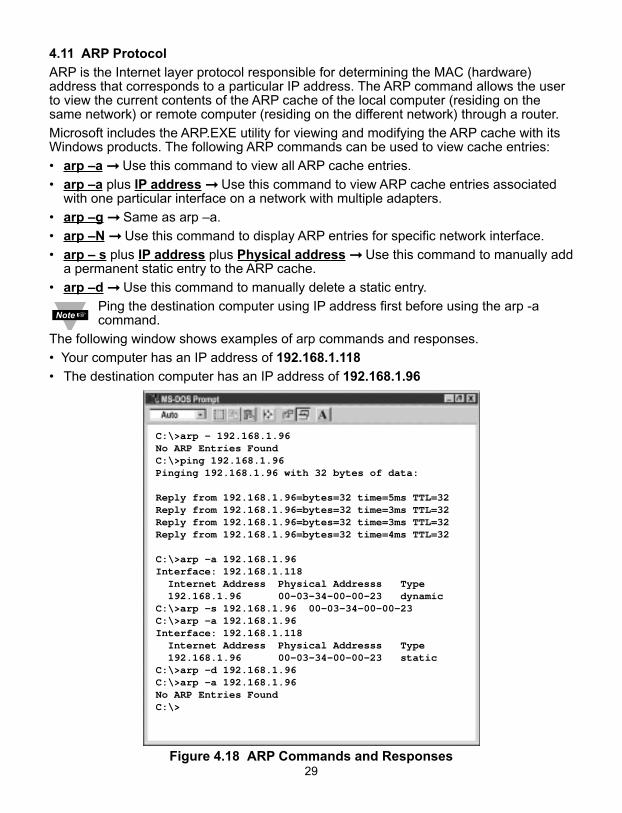
4.11 ARP Protocol
ARP is the Internet layer protocol responsible for determining the MAC (hardware)address that corresponds to a particular IP address. The ARP command allows the userto view the current contents of the ARP cache of the local computer (residing on thesame network) or remote computer (residing on the different network) through a router.
Microsoft includes the ARP.EXE utility for viewing and modifying the ARP cache with itsWindows products. The following ARP commands can be used to view cache entries:
• arp –a ➞ Use this command to view all ARP cache entries.
• arp –a plus IP address ➞ Use this command to view ARP cache entries associated with one particular interface on a network with multiple adapters.
• arp –g ➞ Same as arp –a.
• arp –N ➞ Use this command to display ARP entries for specific network interface.
• arp – s plus IP address plus Physical address ➞ Use this command to manually adda permanent static entry to the ARP cache.
• arp –d ➞ Use this command to manually delete a static entry.
Ping the destination computer using IP address first before using the arp -acommand.
The following window shows examples of arp commands and responses.
• Your computer has an IP address of 192.168.1.118
• The destination computer has an IP address of 192.168.1.96
Figure 4.18 ARP Commands and Responses
C:\>arp - 192.168.1.96No ARP Entries FoundC:\>ping 192.168.1.96Pinging 192.168.1.96 with 32 bytes of data:
Reply from 192.168.1.96=bytes=32 time=5ms TTL=32Reply from 192.168.1.96=bytes=32 time=3ms TTL=32Reply from 192.168.1.96=bytes=32 time=3ms TTL=32Reply from 192.168.1.96=bytes=32 time=4ms TTL=32
C:\>arp -a 192.168.1.96Interface: 192.168.1.118 Internet Address Physical Addresss Type 192.168.1.96 00-03-34-00-00-23 dynamicC:\>arp -s 192.168.1.96 00-03-34-00-00-23C:\>arp -a 192.168.1.96Interface: 192.168.1.118 Internet Address Physical Addresss Type 192.168.1.96 00-03-34-00-00-23 staticC:\>arp -d 192.168.1.96C:\>arp -a 192.168.1.96No ARP Entries FoundC:\>
29
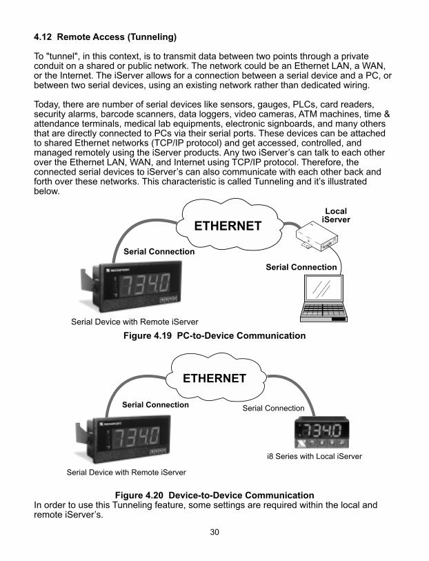
4.12 Remote Access (Tunneling)
To "tunnel", in this context, is to transmit data between two points through a privateconduit on a shared or public network. The network could be an Ethernet LAN, a WAN,or the Internet. The iServer allows for a connection between a serial device and a PC, orbetween two serial devices, using an existing network rather than dedicated wiring.
Today, there are number of serial devices like sensors, gauges, PLCs, card readers,security alarms, barcode scanners, data loggers, video cameras, ATM machines, time &attendance terminals, medical lab equipments, electronic signboards, and many othersthat are directly connected to PCs via their serial ports. These devices can be attachedto shared Ethernet networks (TCP/IP protocol) and get accessed, controlled, andmanaged remotely using the iServer products. Any two iServer’s can talk to each otherover the Ethernet LAN, WAN, and Internet using TCP/IP protocol. Therefore, theconnected serial devices to iServer’s can also communicate with each other back andforth over these networks. This characteristic is called Tunneling and it’s illustratedbelow.
Figure 4.19 PC-to-Device Communication
Figure 4.20 Device-to-Device CommunicationIn order to use this Tunneling feature, some settings are required within the local andremote iServer’s.
30
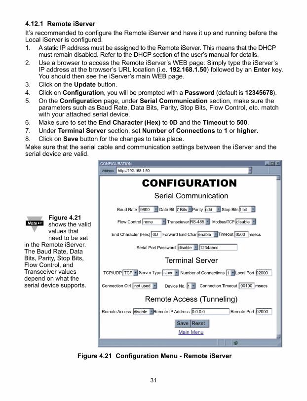
4.12.1 Remote iServer It’s recommended to configure the Remote iServer and have it up and running before theLocal iServer is configured.1. A static IP address must be assigned to the Remote iServer. This means that the DHCP
must remain disabled. Refer to the DHCP section of the user’s manual for details.2. Use a browser to access the Remote iServer’s WEB page. Simply type the iServer’s
IP address at the browser’s URL location (i.e. 192.168.1.50) followed by an Enter key.You should then see the iServer’s main WEB page.
3. Click on the Update button.4. Click on Configuration, you will be prompted with a Password (default is 12345678).5. On the Configuration page, under Serial Communication section, make sure the
parameters such as Baud Rate, Data Bits, Parity, Stop Bits, Flow Control, etc. matchwith your attached serial device.
6. Make sure to set the End Character (Hex) to 0D and the Timeout to 500.7. Under Terminal Server section, set Number of Connections to 1 or higher.8. Click on Save button for the changes to take place.Make sure that the serial cable and communication settings between the iServer and theserial device are valid.
Figure 4.21 Configuration Menu - Remote iServer
CONFIGURATION
CONFIGURATION
http://192.168.1.50Address
Serial Communication
Remote Access (Tunneling)
Terminal Server
Main Menu
Save Reset
Baud Rate 9600 Data Bit 7 Bits Parity odd Stop Bits1 bit
Flow Control none Transciever RS-485 Modbus/TCP disable
End Character (Hex) 0D Forward End Char enable Timeout 0500 msecs
Serial Port Password disable 1234abcd
Connection Ctrl not used Device No. 1 Connection Timeout 00100 msecs
TCP/UDP TCP Server Type slave Number of Connections 1 Local Port 02000
Remote Access disable Remote IP Address 0.0.0.0 Remote Port 02000
31
Figure 4.21shows the validvalues thatneed to be set
in the Remote iServer.The Baud Rate, DataBits, Parity, Stop Bits,Flow Control, andTransceiver valuesdepend on what theserial device supports.
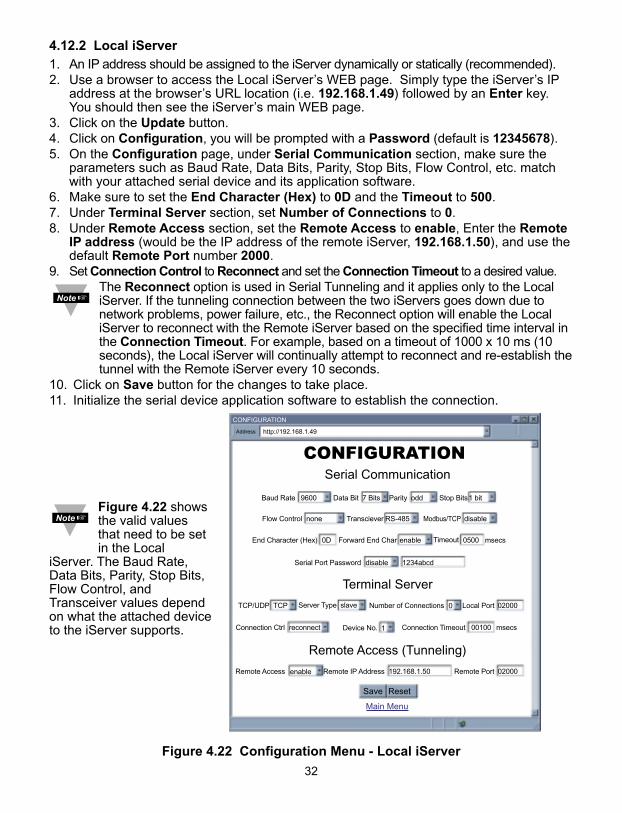
4.12.2 Local iServer 1. An IP address should be assigned to the iServer dynamically or statically (recommended).2. Use a browser to access the Local iServer’s WEB page. Simply type the iServer’s IP
address at the browser’s URL location (i.e. 192.168.1.49) followed by an Enter key.You should then see the iServer’s main WEB page.
3. Click on the Update button.4. Click on Configuration, you will be prompted with a Password (default is 12345678).5. On the Configuration page, under Serial Communication section, make sure the
parameters such as Baud Rate, Data Bits, Parity, Stop Bits, Flow Control, etc. matchwith your attached serial device and its application software.
6. Make sure to set the End Character (Hex) to 0D and the Timeout to 500. 7. Under Terminal Server section, set Number of Connections to 0.8. Under Remote Access section, set the Remote Access to enable, Enter the Remote
IP address (would be the IP address of the remote iServer, 192.168.1.50), and use thedefault Remote Port number 2000.
9. Set Connection Control to Reconnect and set the Connection Timeout to a desired value.The Reconnect option is used in Serial Tunneling and it applies only to the LocaliServer. If the tunneling connection between the two iServers goes down due tonetwork problems, power failure, etc., the Reconnect option will enable the LocaliServer to reconnect with the Remote iServer based on the specified time interval inthe Connection Timeout. For example, based on a timeout of 1000 x 10 ms (10seconds), the Local iServer will continually attempt to reconnect and re-establish thetunnel with the Remote iServer every 10 seconds.
10. Click on Save button for the changes to take place.11. Initialize the serial device application software to establish the connection.
Figure 4.22 Configuration Menu - Local iServer
CONFIGURATION
CONFIGURATION
http://192.168.1.49Address
Serial Communication
Remote Access (Tunneling)
Terminal Server
Main Menu
Save Reset
Baud Rate 9600 Data Bit 7 Bits Parity odd Stop Bits1 bit
Flow Control none Transciever RS-485 Modbus/TCP disable
End Character (Hex) 0D Forward End Char enable Timeout 0500 msecs
Serial Port Password disable 1234abcd
Connection Ctrl reconnect Device No. 1 Connection Timeout 00100 msecs
TCP/UDP TCP Server Type slave Number of Connections 0 Local Port 02000
Remote Access enable Remote IP Address 192.168.1.50 Remote Port 02000
32
Figure 4.22 showsthe valid valuesthat need to be setin the Local
iServer. The Baud Rate,Data Bits, Parity, Stop Bits,Flow Control, andTransceiver values dependon what the attached deviceto the iServer supports.
33
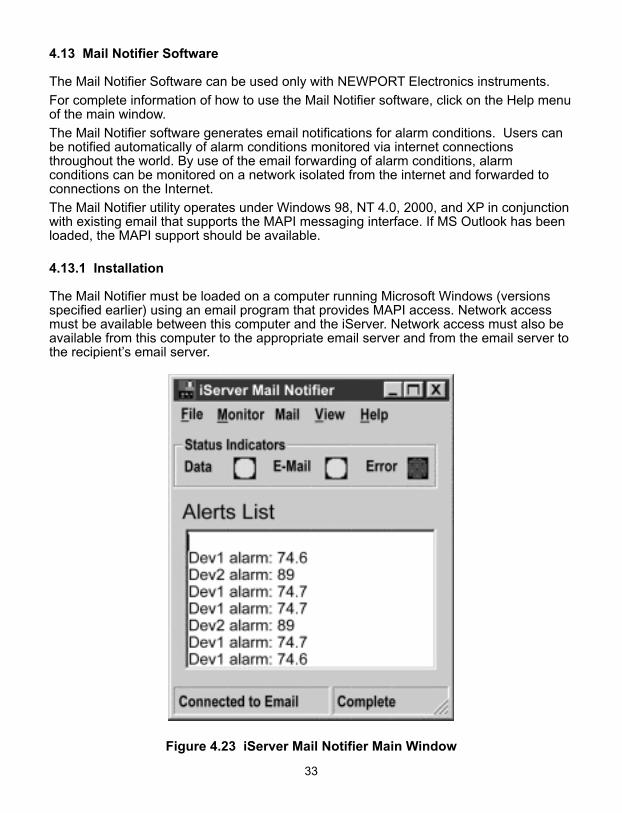
4.13 Mail Notifier Software
The Mail Notifier Software can be used only with NEWPORT Electronics instruments.
For complete information of how to use the Mail Notifier software, click on the Help menuof the main window.
The Mail Notifier software generates email notifications for alarm conditions. Users canbe notified automatically of alarm conditions monitored via internet connectionsthroughout the world. By use of the email forwarding of alarm conditions, alarmconditions can be monitored on a network isolated from the internet and forwarded toconnections on the Internet.
The Mail Notifier utility operates under Windows 98, NT 4.0, 2000, and XP in conjunctionwith existing email that supports the MAPI messaging interface. If MS Outlook has beenloaded, the MAPI support should be available.
4.13.1 Installation
The Mail Notifier must be loaded on a computer running Microsoft Windows (versionsspecified earlier) using an email program that provides MAPI access. Network accessmust be available between this computer and the iServer. Network access must also beavailable from this computer to the appropriate email server and from the email server tothe recipient’s email server.
Figure 4.23 iServer Mail Notifier Main Window
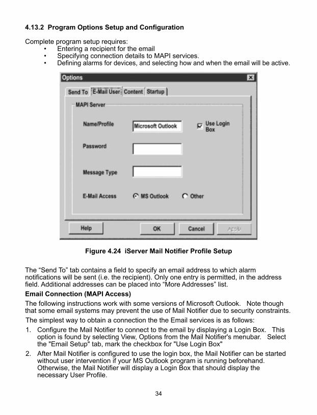
4.13.2 Program Options Setup and Configuration
Complete program setup requires: • Entering a recipient for the email• Specifying connection details to MAPI services.• Defining alarms for devices, and selecting how and when the email will be active.
Figure 4.24 iServer Mail Notifier Profile Setup
The “Send To” tab contains a field to specify an email address to which alarmnotifications will be sent (i.e. the recipient). Only one entry is permitted, in the addressfield. Additional addresses can be placed into “More Addresses” list.
Email Connection (MAPI Access)
The following instructions work with some versions of Microsoft Outlook. Note thoughthat some email systems may prevent the use of Mail Notifier due to security constraints.
The simplest way to obtain a connection the the Email services is as follows:
1. Configure the Mail Notifier to connect to the email by displaying a Login Box. Thisoption is found by selecting View, Options from the Mail Notifier's menubar. Selectthe "Email Setup" tab, mark the checkbox for "Use Login Box"
2. After Mail Notifier is configured to use the login box, the Mail Notifier can be startedwithout user intervention if your MS Outlook program is running beforehand.Otherwise, the Mail Notifier will display a Login Box that should display thenecessary User Profile.
34
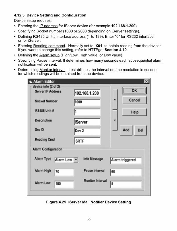
4.12.3 Device Setting and Configuration
Device setup requires:
• Entering the IP address for iServer device (for example 192.168.1.200).
• Specifying Socket number (1000 or 2000 depending on iServer settings).
• Defining RS485 Unit # interface address (1 to 199). Enter "0" for RS232 interface or for iServer.
• Entering Reading command. Normally set to X01 to obtain reading from the devices.If you want to change this setting, refer to HTTPget Section 4.10.
• Defining the Alarm setup (High/Low, High value, or Low value).
• Specifying Pause Interval. It determines how many seconds each subsequential alarmnotification will be sent.
• Determining Monitor interval. It establishes the interval or time resolution in seconds for which readings will be obtained from the device.
Figure 4.25 iServer Mail Notifier Device Setting
35
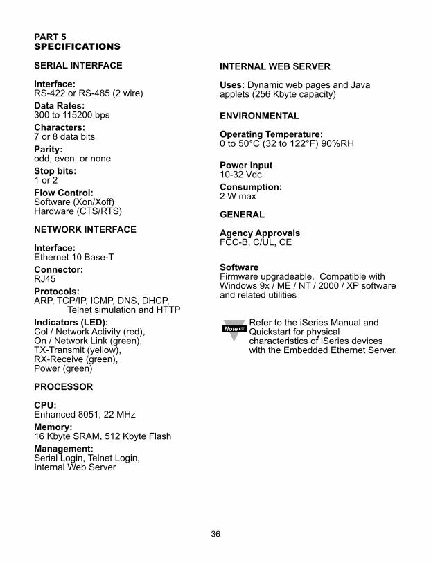
PART 5SPECIFICATIONS
SERIAL INTERFACE
Interface: RS-422 or RS-485 (2 wire)Data Rates: 300 to 115200 bpsCharacters: 7 or 8 data bitsParity: odd, even, or noneStop bits: 1 or 2Flow Control:Software (Xon/Xoff)Hardware (CTS/RTS)
NETWORK INTERFACE
Interface: Ethernet 10 Base-TConnector: RJ45Protocols: ARP, TCP/IP, ICMP, DNS, DHCP,
Telnet simulation and HTTPIndicators (LED):Col / Network Activity (red),On / Network Link (green), TX-Transmit (yellow), RX-Receive (green), Power (green)
PROCESSOR
CPU: Enhanced 8051, 22 MHzMemory: 16 Kbyte SRAM, 512 Kbyte FlashManagement:Serial Login, Telnet Login, Internal Web Server
36
INTERNAL WEB SERVER
Uses: Dynamic web pages and Javaapplets (256 Kbyte capacity)
ENVIRONMENTAL
Operating Temperature: 0 to 50°C (32 to 122°F) 90%RH
Power Input 10-32 VdcConsumption: 2 W max
GENERAL
Agency ApprovalsFCC-B, C/UL, CE
SoftwareFirmware upgradeable. Compatible withWindows 9x / ME / NT / 2000 / XP softwareand related utilities
Refer to the iSeries Manual andQuickstart for physicalcharacteristics of iSeries deviceswith the Embedded Ethernet Server.
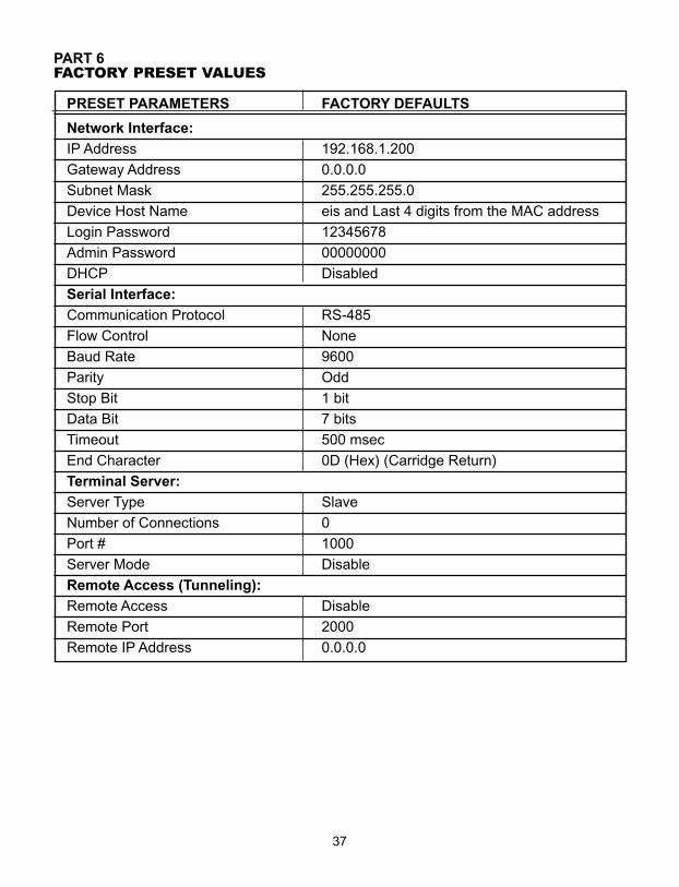
PART 6FACTORY PRESET VALUES
PRESET PARAMETERS FACTORY DEFAULTS
Network Interface:
IP Address 192.168.1.200
Gateway Address 0.0.0.0
Subnet Mask 255.255.255.0
Device Host Name eis and Last 4 digits from the MAC address
Login Password 12345678
Admin Password 00000000
DHCP Disabled
Serial Interface:
Communication Protocol RS-485
Flow Control None
Baud Rate 9600
Parity Odd
Stop Bit 1 bit
Data Bit 7 bits
Timeout 500 msec
End Character 0D (Hex) (Carridge Return)
Terminal Server:
Server Type Slave
Number of Connections 0
Port # 1000
Server Mode Disable
Remote Access (Tunneling):
Remote Access Disable
Remote Port 2000
Remote IP Address 0.0.0.0
37
APPENDIX A GLOSSARY
User of this manual should be familiar with following definitions:
ARP (Address Resolution Protocol) is a protocol for mapping an Internet Protocol address (IP address) to a physical machine address that is recognized in the localnetwork. For example, the IP address in use today is an address that is 32-bits long. In an Ethernet local area network, however, addresses for attached devices are 48-bitslong. (The physical machine address is also known as a Media Access Control or MAC address.) A table, usually called the ARP cache, is used to maintain a correlationbetween each MAC address and its corresponding IP address. ARP provides theprotocol rules for making this correlation and providing address conversion in bothdirections.
Ethernet is a network protocol defined by the IEEE 802.3 standard. Ethernet-based networks use MAC Address rather then IP Address to exchange data betweencomputers. By using ARP and adding TCP/IP support, Ethernet devices may beconnected as part of the Internet. An Ethernet LAN typically uses coaxial cable or specialgrades of twisted pair wires. The most commonly installed Ethernet systems are called10BASE-T and provide transmission speeds up to 10 Mbps. Devices are connected tothe cable and compete for access using a Carrier Sense Multiple Access with CollisionDetection (CSMA/CD) protocol.
IP (Internet Protocol) is the method or protocol by which data is sent from one computerto another on the Internet.
IP address (Internet Protocol address) is a 32-bit number that identifies each senderor receiver of information that is sent in packets across the Internet.
IP Netmask is a 32-bit pattern of bits used to determine which part of the IP address isthe network portion and which part is the host portion.
MAC (Media Access Control) Address is your computer's unique hardware number.When you're connected to the Internet from your computer, a correspondence tablerelates your IP address to your computer's physical (MAC) address on the LAN.
Ping is a utility that tests the network connectivity. It is used to determine if the host iscapable of exchanging information with another host.
Port number/Socket number is a way to identify a specific process to which an Internetor other network message is to be forwarded when it arrives at a server. It is apredefined address that serves as a route from the application to the Transport layer orfrom the Transport layer to the application of the TCP/IP system.
Sockets are a method for communication between a client program and a serverprogram in a network and defined as "the endpoint in a connection." Informationtransferred across the Internet primarily occurs between sockets.
TCP/IP (Transmission Control Protocol/Internet Protocol) is the basic communicationlanguage or protocol of the Internet. When you are set up with direct access to theInternet, your computer is provided with a copy of the TCP/IP program just as everyother computer that you may send messages to or get information from also has a copyof TCP/IP. TCP/IP often is used as a general term to indicate generic access to theInternet.
38
39
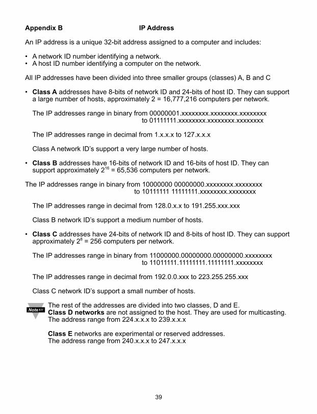
Appendix B IP Address
An IP address is a unique 32-bit address assigned to a computer and includes:
• A network ID number identifying a network.• A host ID number identifying a computer on the network.
All IP addresses have been divided into three smaller groups (classes) A, B and C
• Class A addresses have 8-bits of network ID and 24-bits of host ID. They can support a large number of hosts, approximately 2 = 16,777,216 computers per network.
The IP addresses range in binary from 00000001.xxxxxxxx.xxxxxxxx.xxxxxxxxto 01111111.xxxxxxxx.xxxxxxxx.xxxxxxxx
The IP addresses range in decimal from 1.x.x.x to 127.x.x.x
Class A network ID’s support a very large number of hosts.
• Class B addresses have 16-bits of network ID and 16-bits of host ID. They can support approximately 216 = 65,536 computers per network.
The IP addresses range in binary from 10000000 00000000.xxxxxxxx.xxxxxxxxto 10111111 11111111.xxxxxxxx.xxxxxxxx
The IP addresses range in decimal from 128.0.x.x to 191.255.xxx.xxx
Class B network ID’s support a medium number of hosts.
• Class C addresses have 24-bits of network ID and 8-bits of host ID. They can support approximately 28 = 256 computers per network.
The IP addresses range in binary from 11000000.00000000.00000000.xxxxxxxx to 11011111.11111111.11111111.xxxxxxxx
The IP addresses range in decimal from 192.0.0.xxx to 223.255.255.xxx
Class C network ID’s support a small number of hosts.
The rest of the addresses are divided into two classes, D and E.Class D networks are not assigned to the host. They are used for multicasting. The address range from 224.x.x.x to 239.x.x.x
Class E networks are experimental or reserved addresses.The address range from 240.x.x.x to 247.x.x.x
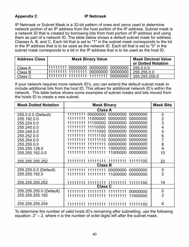
Appendix C IP Netmask
IP Netmask or Subnet Mask is a 32-bit pattern of ones and zeros used to determinenetwork portion of an IP address from the host portion of the IP address. Subnet mask isa network ID that is created by borrowing bits from host portion of IP address and usingthem as part of a network ID. The table below shows a default subnet mask for addressClasses A, B, and C. Each bit that is set to "1" in the subnet mask corresponds to the bitin the IP address that is to be used as the network ID. Each bit that is set to "0" in thesubnet mask corresponds to a bit in the IP address that is to be used as the host ID.
Address Class Mask Binary Value Mask Decimal Valueor Dotted Notation
Class A 255.0.0.0Class B 255.255.0.0Class C 255.255.255.0
If your network requires more network ID’s, you can extend the default subnet mask toinclude additional bits from the host ID. This allows for additional network ID’s within thenetwork. The table below shows some examples of subnet masks and bits moved fromthe hosts ID to create a new subnet.
Mask Dotted Notation Mask Binary Mask BitsClass A
255.0.0.0 (Default) 0255.192.0.0 2255.224.0.0 3255.240.0.0 4255.248.0.0 5255.252.0.0 6255.254.0.0 7255.255.0.0 8255.255.128.0 9255.255.192.0.0 10……………......... .255.255.255.252 22
Class B255.255.0.0 (Default) 0255.255.192.0 2……………......... .255.255.255.252 14
Class C255.255.255.0 (Default) 0255.255.255.192 2…………………. .255.255.255.254 6
To determine the number of valid hosts ID’s remaining after subnetting, use the followingequation: 2n – 2, where n is the number of octet digits left after the subnet mask.
40
111111111111111111111111
000000001111111111111111
000000000000000011111111
000000000000000000000000
11111111111111111111111111111111111111111111111111111111111111111111111111111111. . . . . . . .11111111
00000000110000001110000011110000111110001111110011111110111111111111111111111111. . . . . . . .11111111
00000000000000000000000000000000000000000000000000000000000000001000000011000000. . . . . . . .11111111
00000000000000000000000000000000000000000000000000000000000000000000000000000000. . . . . . . .11111100
1111111111111111. . . . . . . .11111111
1111111111111111. . . . . . . .11111111
0000000011000000. . . . . . . .11111111
0000000000000000. . . . . . . .11111100
1111111111111111. . . . . . . .11111111
1111111111111111. . . . . . . .11111111
1111111111111111. . . . . . . .11111111
0000000011000000. . . . . . . .11111100
Appendix D ASCII Chart
ASCII Dec Hex Binary ASCII Dec Hex BinaryChar No Parity Char No parityNUL 00 00 00000000 @ 64 40 01000000SOH 01 01 00000001 A 65 41 01000000STX 02 02 00000010 B 66 42 01000010ETX 03 03 00000011 C 67 43 01000011EOT 04 04 00000100 D 68 44 01000100ENQ 05 05 00000101 E 69 45 01000101ACK 06 06 00000110 F 70 46 01000110BEL 07 07 00000111 G 71 47 01000111BS 08 08 00001000 H 72 48 01001000HT 09 09 00001001 I 73 49 01001001LF 10 0A 00001010 J 74 4A 01001010VT 11 0B 00001011 K 75 4B 01001011FF 12 0C 00001100 L 76 4C 01001100CR 13 0D 00001101 M 77 4D 01001101SO 14 0E 00001110 N 78 4E 01001110SI 15 0F 00001111 O 79 4F 01001111
DLE 16 10 00010000 P 80 50 01010000DC1 17 11 00010001 Q 81 51 01010001DC2 18 12 00010010 R 82 52 01010010DC3 19 13 00010011 S 83 53 01010011DC4 20 14 00010100 T 84 54 01010100NAK 21 15 00010101 U 85 55 01010101SYN 22 16 00010110 V 86 56 01010110ETB 23 17 00010111 W 87 57 01010111CAN 24 18 00011000 X 88 58 01011000EM 25 19 00011001 Y 89 59 01011001
SUB 26 1A 00011010 Z 90 5A 01011010ESC 27 1B 00011011 [ 91 5B 01011011FS 28 1C 00011100 \ 92 5C 01011100GS 29 1D 00011101 ] 93 5D 01011101RS 30 1E 00011110 ^ 94 5E 01011110US 31 1F 00011111 _ 95 5F 01011111SP 32 20 00100000 ` 96 60 01100000! 33 21 00100001 a 97 61 01100001" 34 22 00100010 b 98 62 01100010# 35 23 00100011 c 99 63 01100011$ 36 24 00100100 d 100 64 01100100% 37 25 00100101 e 101 65 01100101& 38 26 00100110 f 102 66 01100110‘ 39 27 00100111 g 103 67 01100111( 40 28 00101000 h 104 68 01101000) 41 29 00101001 I 105 69 01101001* 42 2A 00101010 j 106 6A 01101010+ 43 2B 00101011 k 107 6B 01101011, 44 2C 00101100 l 108 6C 01101100- 45 2D 00101101 m 109 6D 01101101. 46 2E 00101110 n 110 6E 01101110
41
Appendix D ASCII Chart Continuation/ 47 2F 00101111 o 111 6F 011011110 48 30 00110000 p 112 70 011100001 49 31 00110001 q 113 71 011100012 50 32 00110010 r 114 72 011100103 51 33 00110011 s 115 73 011100114 52 34 00110100 t 116 74 011101005 53 35 00110101 u 117 75 011101016 54 36 00110110 v 118 76 011101107 55 37 00110111 w 119 77 011101118 56 38 00111000 x 120 78 011110009 57 39 00111001 y 121 79 01111001: 58 3A 00111010 z 122 7A 01111010; 59 3B 00111011 { 123 7B 01111011< 60 3C 00111100 | 124 7C 01111100= 61 3D 00111101 } 125 7D 01111101> 62 3E 00111110 ~ 126 7E 01111110? 63 3F 00111111 DEL 127 7F 01111111
ASCII Control CodesASCII Dec Hex Ctrl Key Definition ASCII Dec Hex Ctrl Key DefinitionChar Equiv. Char Equiv.NUL 00 00 Crtl @ Null Character DC1 17 11 Crtl Q Data Control 1
- XONSOH 01 01 Crtl A Start of DC2 18 12 Crtl R Data Control 2
HeaderSTX 02 02 Crtl B Start of Text DC3 19 13 Crtl S Data Control 3
- XOFFETX 03 03 Crtl C End of Text DC4 20 14 Crtl T Data Control 4EOT 04 04 Crtl D End of NAK 21 15 Crtl U Negative
Transmission AcknowledgeENQ 05 05 Crtl E Inquiry SYN 22 16 Crtl V Synchronous
IdleACK 06 06 Crtl F Acknowledge ETB 23 17 Crtl W End of Trans
BlockBEL 07 07 Crtl G Bell CAN 24 18 Crtl X CancelBS 08 08 Crtl H Back Space EM 25 19 Crtl Y End of MediumHT 09 09 Crtl I Horizontal SUB 26 1A Crtl Z Substitute
TabulationLF 10 0A Crtl J Line Feed ESC 27 1B Crtl [ EscapeVT 11 0B Crtl K Vertical FS 28 1C Crtl \ File Separator
TabulationFF 12 0C Crtl L Form Feed GS 29 1D Crtl ] Group
SeparatorCR 13 0D Crtl M Carriage RS 30 1E Crtl | Record
Return SeparatorSO 14 0E Crtl N Shift Out US 31 1F Crtl _ Unit SeparatorSI 15 0F Crtl O Shift In SP 32 20 Space
DLE 16 10 Crtl P Data LinkEscape
42

43
PART 7APPROVALS INFORMATION7.1 CE APPROVALS INFORMATION
This product conforms to the EMC directive 89/336/EEC amended by93/68/EEC, and with the European Low Voltage Directive 72/23/EEC.
Electrical Safety EN61010-1:2001Safety requirements for electrical equipment for measurement, control andlaboratory.Double InsulationPollution Degree 2Dielectric withstand Test per 1 min
• Power to Input/Output: 2300Vac (3250Vdc)• Power to Input/Output: 1500Vac (2120Vdc)
(Low Voltage dc Power Option*)
• Power to Relays/SSR Output: 2300Vac (3250Vdc)• Ethernet to Inputs: 1500Vac (2120Vdc)• Isolated RS232 to Inputs: 500Vac (720Vdc)• Isolated Analog to Inputs: 500Vac (720Vdc)• Analog/Pulse to Inputs: No Isolation
Measurement Category ICategory I are measurements performed on circuits not directly connected to theMains Supply (power). Maximum Line-to-Neutral working voltage is 50Vac/dc.This unit should not be used in Measurement Categories II, III, IV.
Transients Overvoltage Surge (1.2 / 50uS pulse)• Input Power: 2500V• Input Power: 1500V
(Low Voltage dc Power Option*)
• Ethernet: 1500V• Input/Output Signals: 500V
Note: *Units configured for external low power dc voltage, 12-36Vdc
EMC EN61326:1997 + and A1:1998 + A2:2001Immunity and Emissions requirements for electrical equipment for measurement,control and laboratory.
• EMC Emissions Table 4, Class B of EN61326• EMC Immunity** Table 1 of EN61326
Note: **I/O signal and control lines require shielded cables and these cables mustbe located on conductive cable trays or in conduits. Furthermore, the lengthof these cables should not exceed 30 meters
Refer to the EMC and Safety installation considerations (Guidelines) of thismanual for additional information.
7.2 FCCThis device complies with Part 15, Subpart B, Class B of the FCC rules.

Warranty/DisclaimerNEWPORT Electronics, Inc. warrants this unit to be free of defects in materials and workmanship for a period of one(1) year from the date of purchase. In addition to NEWPORT’s standard warranty period, NEWPORT Electronics willextend the warranty period for four (4) additional years if the warranty card enclosed with each instrument isreturned to NEWPORT.
If the unit should malfunction, it must be returned to the factory for evaluation. NEWPORT’s Customer ServiceDepartment will issue an Authorized Return (AR) number immediately upon phone or written request. Uponexamination by NEWPORT, if the unit is found to be defective it will be repaired or replaced at no charge.NEWPORT’s WARRANTY does not apply to defects resulting from any action of the purchaser, including but notlimited to mishandling, improper interfacing, operation outside of design limits, improper repair, or unauthorizedmodification. This WARRANTY is VOID if the unit shows evidence of having been tampered with or shows evidenceof being damaged as a result of excessive corrosion; or current, heat, moisture or vibration; improper specification;misapplication; misuse or other operating conditions outside of NEWPORT’s control. Components which wear are notwarranted, including but not limited to contact points, fuses, and triacs.
NEWPORT is pleased to offer suggestions on the use of its various products. However, NEWPORT neitherassumes responsibility for any omissions or errors nor assumes liability for any damages that result fromthe use of its products in accordance with information provided by NEWPORT, either verbal or written.NEWPORT warrants only that the parts manufactured by it will be as specified and free of defects.NEWPORT MAKES NO OTHER WARRANTIES OR REPRESENTATIONS OF ANY KIND WHATSOEVER,EXPRESSED OR IMPLIED, EXCEPT THAT OF TITLE, AND ALL IMPLIED WARRANTIES INCLUDING ANYWARRANTY OF MERCHANTABILITY AND FITNESS FOR A PARTICULAR PURPOSE ARE HEREBYDISCLAIMED. LIMITATION OF LIABILITY: The remedies of purchaser set forth herein are exclusive and thetotal liability of NEWPORT with respect to this order, whether based on contract, warranty, negligence,indemnification, strict liability or otherwise, shall not exceed the purchase price of the component uponwhich liability is based. In no event shall NEWPORT be liable for consequential, incidental or specialdamages.
CONDITIONS: Equipment sold by NEWPORT is not intended to be used, nor shall it be used: (1) as a “BasicComponent” under 10 CFR 21 (NRC), used in or with any nuclear installation or activity; or (2) in medical applicationsor used on humans. Should any Product(s) be used in or with any nuclear installation or activity, medical application,or used on humans, or misused in any way, NEWPORT assumes no responsibility as set forth in our basicWARRANTY / DISCLAIMER language, and additionally purchaser will indemnify NEWPORT and hold NEWPORTharmless from any liability or damage whatsoever arising out of the use of the Product(s) in such a manner.
Direct all warranty and repair requests/inquiries to the NEWPORT Customer Service Department.BEFORE RETURNING ANY PRODUCT(S) TO NEWPORT, PURCHASER MUST OBTAIN ANAUTHORIZED RETURN (AR) NUMBER FROM NEWPORT’S CUSTOMER SERVICE DEPARTMENT (INORDER TO AVOID PROCESSING DELAYS). The assigned AR number should then be marked on theoutside of the return package and on any correspondence.
The purchaser is responsible for shipping charges, freight, insurance and proper packaging to preventbreakage in transit.
FOR WARRANTY RETURNS, please have thefollowing information available BEFORE contacting NEWPORT:
1. P.O. number under which the product wasPURCHASED,
2. Model and serial number of the productunder warranty, and
3. Repair instructions and/or specificproblems relative to the product.
FOR NON-WARRANTY REPAIRS, consultNEWPORT for current repair charges. Have thefollowing information available BEFORE contactingNEWPORT:
1. P.O. number to cover the COST of the repair,
2. Model and serial number of product, and3. Repair instructions and/or specific problems
relative to the product.
NEWPORT’s policy is to make running changes, not model changes, whenever an improvement is possible.This affords our customers the latest in technology and engineering.NEWPORT is a registered trademark of NEWPORT Electronics, Inc.© Copyright 2006 NEWPORT Electronics, Inc. All rights reserved. This document may not be copied,photocopied, reproduced, translated, or reduced to any electronic medium or machine-readable form, inwhole or in part, without prior written consent of NEWPORT Electronics, Inc.
Return Requests/Inquiries

M3629/N/0606
For immediate technical or application assistance please call:
Newport Electronics, Inc.2229 South Yale Street • Santa Ana, CA • 92704 • U.S.A.
TEL: (714) 540-4914 • FAX: (203) 968-7311Toll Free: 1-800-639-7678 • www.newportUS.com • e-mail:[email protected]
ISO 9001 Certified
Newport Technologies, Inc.976 Bergar • Laval (Quebec) • H7L 5A1 • Canada
TEL: (514) 335-3183 • FAX: (514) 856-6886Toll Free: 1-800-639-7678 • www.newport.ca • e-mail:[email protected]
Newport Electronics, Ltd.One Omega Drive • River Bend Technology Centre
Northbank, Irlam • Manchester M44 5BD • United KingdomTel: +44 161 777 6611 • FAX: +44 161 777 6622
Toll Free: 0800 488 488 • www.newportuk.co.uk • e-mail:[email protected]
Newport Electronics spol s.r.o.Frystatska 184, 733 01 Karviná • Czech RepublicTEL: +420 59 6311899 • FAX: +420 59 6311114
Toll Free: 0800-1-66342 • www.newport.cz • e-mail: [email protected]
Newport Electronics GmbHDaimlerstrasse 26 • D-75392 Deckenpfronn • Germany
TEL: 49 7056 9398-0 • FAX: 49 7056 9398-29Toll Free: 0800 / 6397678 • www.newport.de • e-mail: [email protected]
Mexico and Latin AmericaFAX: 001 (203) 359-7807
En Español: 001 (203) 359-7803


![Windows iSeries Access - ibm.com · .Comm RC=xxxx - ( ) xxxx 16 . .: ID iSeries Access Windows iSeries Access . 22 IBM - iSeries: Windows iSeries Access: iSeries DB2 UDB [IBM] [iSeries](https://img.pdfslide.us/doc/110x75/5ad38ee67f8b9a92258ea836/windows-iseries-access-ibmcom-rcxxxx-xxxx-16-id-iseries-access-windows.jpg)