Embed Size (px)
Citation preview
Construction History Vol. 11. 1996
Embankments and Cuttings on the early Railways
A W SKEMPTON
Introduction
Between 1834 and 1841 nine main lines of railway were built in England totalling 660 miles in length complete with tunnels, bridges, viaducts and stations and involving the excavation, in cuttings, of some 70 million cu.yd (54 million cu.m) of material, most of which was used in making embankments. Construction on this scale had no precedent. The earthwork quantities, in particular, are astonishing. Apart from the vast total amount, about 2 to 3 million cu.yd of excavation (and banking) was achieved on each line per year averaged over the whole period of its construction (Table 1); figures not much less than the rate of work on the Great Central Railway in the 1890s, using 40 steam navvies and upwards of 100 locomotives, and substantially exceeded, on works of a comparable nature, only with the introduction of modem earthmoving plant on the first 55 mile length of the M1 Motorway in 1958, where 11 million cu.yd were excavated and placed in (well-compacted) embankments at an average rate of 7 million cu.yd per year'. Yet one looks almost in vain in modem histories for details of the methods employed, the results obtained or the difficulties encountered in making embankments and cuttings on the early railways.
Table 1: Excavation Quantities
DATE LENGTH EXCAVATION
RAILWAY WORK LINE MILES VOLUME BEGAN OPENED
By contrast, as these were subjects of great concern to the engineers and contractors involved, there is plenty of information available chiefly in reports and parliamentary papers, together with articles in the Civil Engineer & Architect's Journal and an important paper in Proceedings of the Institution of Civil Engineers as well as several books, all published before 1846. This material forms the basis of the present paper.
Management
The high rates of construction were achieved by good organisation and a large work force. Data are given in Table 2, where the numbers of men employed include bricklayers and masons as well as navvies, but not the brickmakers and quanymen2. Locomotives and staionary engines were used on some of the earthwork operations, and in addition there would be several small steam engines for pumping excavations.
Embankments and Cuttings o n the early Railways
Table 2: Worldorce
I I 1 RAILWAY
As for organisation, the plan adopted on the Londo'n & Brighton Railway is typical: under the engineer-in-chief John Rastrick there were three resident engineers in charge of three divisions of the line and another responsible for the tunnels, each with three or four assistants. The 48 mile length was divided into 14 contracts, plus separate contracts for three long tunnels, and on every contract there was a superintendent or agent directing the gangs, many of which worked as sub-contractors.
Great Western
Midland Counties
Midland Counties
London & Brlghton
London & Brighton
Excavation and End-Tipping
DATES
All 'soft ground' including clay, gravel and the softer variety of Chalk was excavated by pick and shovel. Hard rock had to be blasted. For example, in Blisworth cutting on the London & Birmingham Railway up to a ton of gunpowder was used per week in blasting the limestone (270,000 cu.yd out of a total 870,000, mostly excavated between December 1836 and May 1838)3. In an intermediate category of soft rock a (horse-drawn) plough proved to be most effective. This seems to have been introduced by the contractor Joseph Thornton in 1835 while excavating Keuper Marl in the deep cutting at Yardley, also on the London & Birmingham, where, as usual, the excavated material was taken into an adjacent embankment. According to an account written four years later:
NUMBERS EMPLOYED
Jul. 1837 Dec. 1838 May 1839 Jan. 1840
Jul. 1840
after a few trials, and by increasing the strength and altering the form of the plough, the plan was crowned with a success far beyond what was originally contemplated; for it was found that, in addition to dispensing with a number of men employed in undermining, wedging and breaking up, it reduced the material to such small pieces that the labour of several men, who used to break it up at the foot of the embankment, was saved; and many excavations are now entirely worked with the p l o ~ g h . ~
STATIONARY ENGINES
Clearly it was desirable so far as possible to balance 'cut' and 'fill', both in total and over relatively short distances. Admittedly it was not difficult to excavate a cutting and simply run the material to spoil banks nearby, or to build an embankment from borrow pits along each side of its base (the process of 'side-cutting'). But the total cost would be roughly double that involved in building embankments of material from cuttings; while extra land was required outside the normal boundaries, and useless spoil banks or pits would be left alongside the line. Locally such methods had to be adopted to overcome a deficiency of banking material or an excess of excavation, and sometimes they were used to expedite construction. But as a general rule embankments were formed from cuttings, not too far distant, the excavated material being carried in earth waggons drawn by horses or, for distances of more than about two miles, by locomotives. An integrated system of cutting and embanking was therefore achieved, capable of handling large quantities in a reasonably short time.
LOCOS MEN
6250
4030
5140
4370
621 0
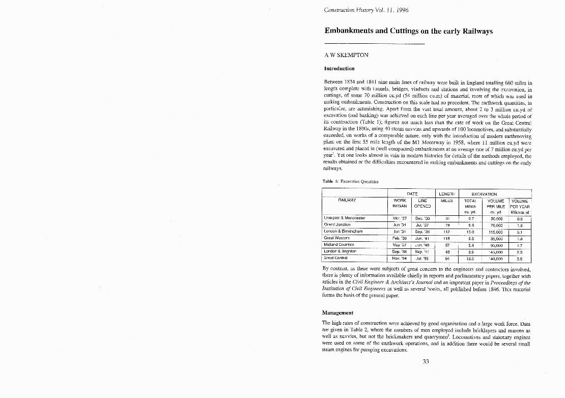
Fig 1: Cutting and embanking, from 'Resident Assistant Engineer' (J.D. Hughes), A Practical Inquiry into the lnws of Excavation and Embankments upon Railways (1840).
HORSES
Now the best way of building an embankment, especially in clay, would have been to form the bank in shallow layers, say 2 to 4 ft thick, running out each of them to the full length, and following with the upper layers after each of the lower ones was laid and compacted with 'beetles' or punners. The bank is thus progressively raised and there is time for some consolidation in the bank and foundation. This was the method (with 4 ft layers) specified by John Macneill in 1836 for embankments on the Slamannan Railway in Scotland (12 miles long, built 1837-40) where the strata chiefly consists of Boulder Clay overlying Coal Measures and the total excavation amounted only to 1 million cu.yd, the largest embankment being 40 ft high with 2:l slopes and 180,000 cu.yd. of fill5.
It was also quite usual to compact in layers that portion of an embankment immediately adjacent to the abutment of a viaduct6. But construction of the whole of an embankment in shallow layers was too slow a process, and one not well suited to the combined operations of cutting and embanking on a large scale. Instead, the method most commonly used on the railways by the mid 1830s was to run out the bank to its full height at once, by end-tipping from the advancing head of the bank on a level with the bottom of the cutting.
The procedure is illustrated in Fig. 1. The cutting has been started by
A', ,*,' '$, opening a 'gullet' 8 ft deep. Above ,, I I this the 'second lift' is being worked
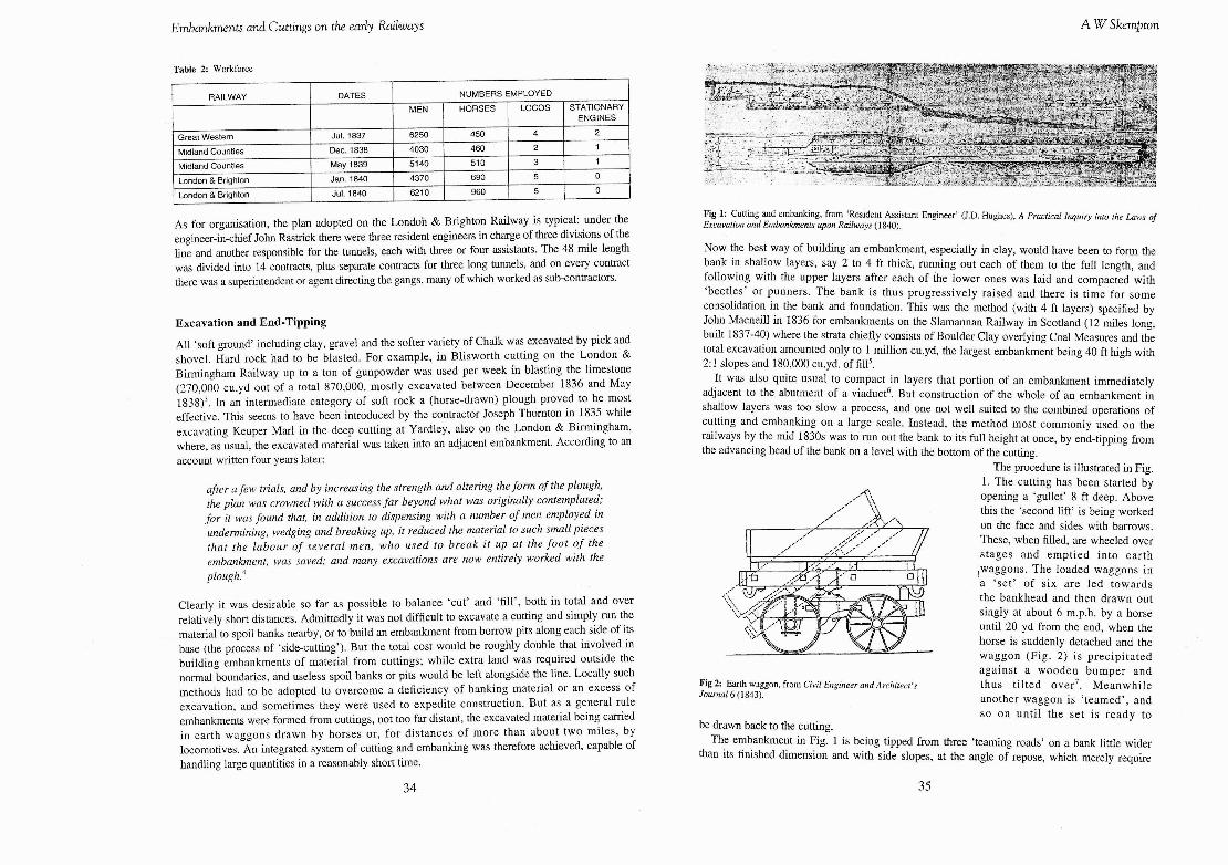
,/' ,,," ..V, ,\> on the face and sides with barrows. These, when filled, are wheeled over stages and emptied into earth ,waggons. The loaded waggons in a 'set ' of six are led towards the bankhead and then drawn out singly at about 6 m.p.h. by a horse until 20 yd from the end, when the horse is suddenly detached and the waggon (Fig. 2) is precipitated against a wooden bumper and
Fig 2: E m h waggon, from Civil Engineer andilrchitect's thus tilted over7. Meanwhile Journal 6 (1843). another waggon is 'teamed', and
so on until the set is ready to he drawn back to the cutting.
The embankment in Fig. 1 is being tipped from three 'teaming roads' on a hank little wider than its finished dimension and with side slopes, at the angle of repose, which merely require
450
460
510
690 960
4
2
3
5 5
- -
2
1
1
0
0
Embankments and Cuttings on the early Railways A W Skempton
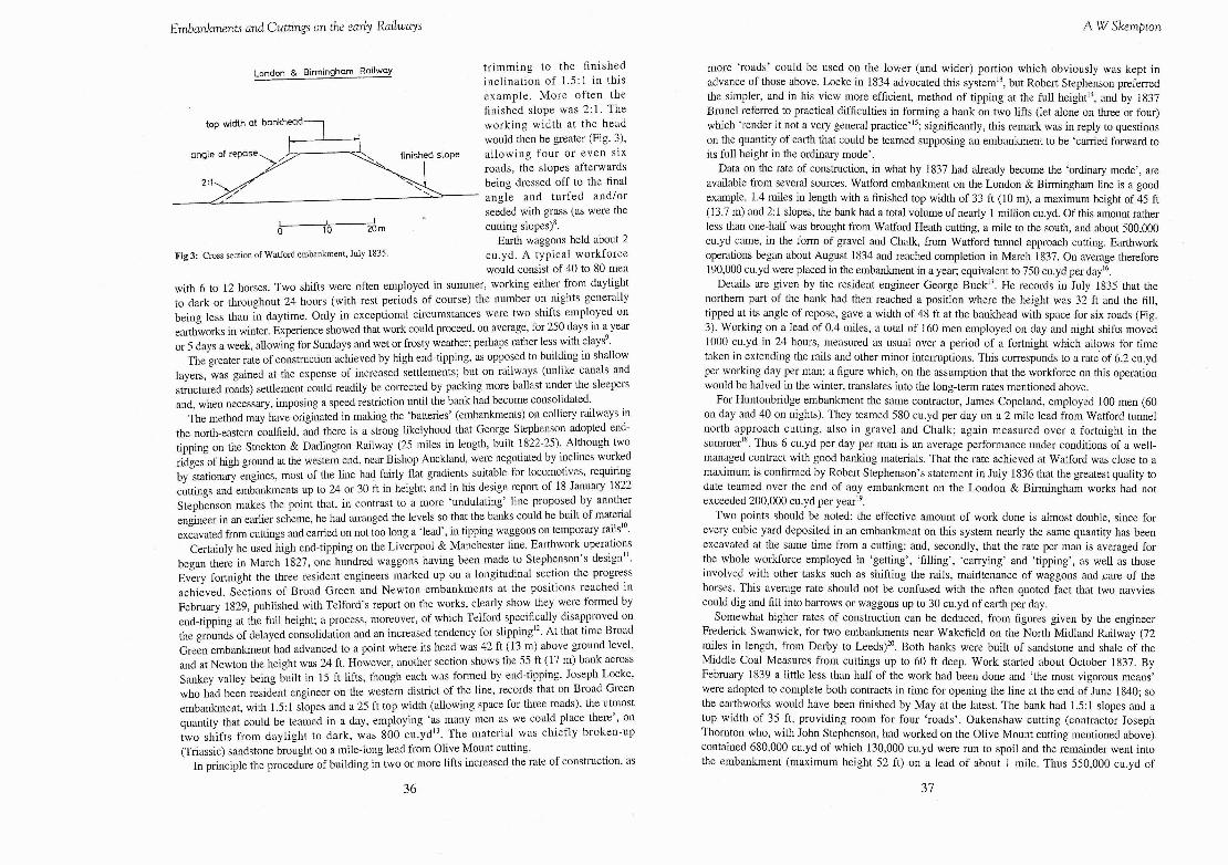
London & Birmingham Railway trimming to the finished inclination of 1.5:l in this example. More often the finished slope was 2 : l . The working width at the head would then be greater (Fig. 3),
ope allowing four or even six roads, the slopes afterwards being dressed off to the final angle and turfed and/or seeded with grass (as were the
I I
0 10 20 m cutting slope^)^. Earth waggons held about 2
Fig 3: Cross section of Watford embankment, July 1835. cu.yd. A typical workforce would consist of 40 to 80 men
with 6 to 12 horses. Two shifts were often employed in summer, working either from daylight to dark or throughout 24 hours (with rest periods of course) the number on nights generally being less than in daytime. Only in exceptional circumstances were two shifts employed on earthworks in winter. Experience showed that work could proceed, on average, for 250 days in a year or 5 days a week, allowing for Sundays and wet or frosty weather; perhaps rather less with clay?.
The greater rate of construction achieved by high end-tipping, as opposed to building in shallow layers, was gained at the expense of increased settlements; but on railways (unlike canals and structured roads) settlement could readily be corrected by packing more ballast under the sleepers and, when necessary, imposing a speed restriction until the bank had become consolidated.
The method may have originated in making the 'batteries' (embankments) on colliery railways in the north-eastem coalfield, and there is a strong likelyhood that George Stephenson adopted end- tipping on the Stockton & Darlington Railway (25 miles in length, built 1822-25). Altho~~gh two ridges of high ground at the western end, near Bishop Auckland, were negotiated by inclines worked by stationary engines, most of the line had fairly flat gradients suitable for locomotives, requiring cuttings and embankments up to 24 or 30 ft in height; and in his design report of 18 January 1822 Stephenson makes the point that, in contrast to a more 'undulating' line proposed by another engineer in an earlier scheme, he had arranged the levels so that the banks could be built of material excavated from cuttings and can-ied on not too long a 'lead', in tipping waggons on temporary rails''.
Certainly he used high end-tipping on the Liverpool & Manchester line. Earthwork operations began there in March 1827, one hundred waggons having been made to Stephenson's design1'. Eveiy fortnight the three resident engineers marked up on a longitudinal section the progress achieved. Sections of Broad Green and Newton embankments at the positions reached in February 1829, published with Telford's report on the works, clearly show they were formed by end-tipping at the full height; a process, moreover, of which Telford specifically disapproved on the grounds of delayed consolidation and an increased tendency for slippingI2. At that time Broad Green embankment had advanced to a point where its head was 42 ft (13 m) above ground level, and at Newton the height was 24 ft. However, another section shows the 55 ft (17 m) bank across Sankey valley being built in 15 ft lifts, though each was formed by end-tipping. Joseph Locke, who had been resident engineer on the western district of the line, records that on Broad Green embankment, with 1.5:l slopes and a 25 ft top width (allowing space for three roads), the utmost q~~antity that could he teamed in a day, employing 'as many men as we could place there', on two shifts from daylight to dark, was 800 cu.ydI3. The material was chiefly broken-up (Triassic) sandstone brought on a mile-long lead from Olive Mount cutting.
In principle the procedure of building in two or more lifts increased the rate of construction, as
36
more 'roads' could be used on the lower (and wider) portion which obviously was kept in advance of those above. Locke in 1834 advocated this system", but Robert Stephenson preferred the simpler, and in his view more efficient, method of tipping at the full heightL4, and by 1837 Brunel referred to practical difficulties in forming a hank on two lifts (let alone on three or four) which 'render it not a very general practice'I5; significantly, this remark was in reply to questions on the quantity of earth that could be teamed supposing an embankment to he 'canied forward to its full height in the ordinary mode'.
Data on the rate of constmction, in what by 1837 had already become the 'ordinary mode', are available from several sources. Watford embankment on the London & Birmingham line is a good example. 1.4 miles in length with a finished top width of 33 ft (10 m), a maximum height of 45 ft (13.7 m) and 2:l slopes, the bank had a total volume of nearly 1 million cu.yd. Of this amount rather less than one-half was brought from Watford Heath cutting, a mile to the south, and about 500,000 cu.yd came, in the form of gravel and Chalk, from Watford tunnel approach cutting. Earthwork operations began about August 1834 and reached completion in March 1837. On average therefore 190,000 cn.yd were placed in the embankment in a year; equivalent to 750 cu.yd per dayi6.
Details are given by the resident engineer George BuckI7. He records in July 1835 that the northern part of the bank bad then reached a position where the height was 32 ft and the fill, tipped at its angle of repose, gave a width of 48 ft at the bankhead with space for six roads (Fig. 3). Working on a lead of 0.4 miles, a total of 160 men employed on day and night shifts moved 1000 cu.yd in 24 hours, measured as usual over a period of a fortnight which allows for time taken in extending the rails and other minor intemptions. This corresponds to a rate of 6.2 cu.yd per working day per man; a figure which, on the assumption that the workforce on this operation would be halved in the winter, translates into the long-term rates mentioned above.
For Huntonbridge embankment the same contractor, James Copeland, employed 100 men (60 on day and 40 on nights). They teamed 580 cu.yd per day on a 2 mile lead from Watford tunnel north approach cutting, also in gravel and Chalk; again measured over a fortnight in the summer'! Thus 6 cu.yd per day per man is an average performance under conditions of a well- managed contract with good banking materials. That the rate achieved at Watford was close to a maximum is confirmed by Robert Stephenson's statement in July 1836 that the greatest quality to date teamed over the end of any embankment on the London & Birmingham works had not exceeded 200,000 cu.yd per yearI9.
Two points should be noted: the effective amount of work done is almost double, since for every cubic yard deposited in an embankment on this system nearly the same quantity has been excavated at the same time from a cutting: and, secondly, that the rate per man is averaged for the whole workforce employed in 'getting', 'filling', 'carrying' and 'tipping', as well as those involved with other tasks such as shifting the rails, mairitenance of waggons and .care of the horses. This average rate should not be confused with the often quoted fact that two navvies could dig and fill into barrows or waggons up to 30 cu.yd of earth per day.
Somewhat higher rates of construction can he deduced, from figures given by the engineer Frederick Swanwick, for two embankments near Wakefield on the North Midland Railway (72 miles in length, from Derby to Leed~)~'. Both banks were built of sandstone and shale of the Middle Coal Measures from cuttings up to 60 ft deep. Work started about October 1837. By Fehn~ary 1839 a little less than half of the work had been done and 'the most vigorous means' were adopted to complete both contracts in time for opening the line at the end of June 1840; so the earthworks would have been finished by May at the latest. The hank had 1.5:l slopes and a top width of 35 ft, providing room for four 'roads'. Oakenshaw cutting (contractor Joseph Thornton who, with John Stephenson, had worked on the Olive Mount cutting mentioned above). contained 680,000 cu.yd of which 130,000 cu.yd were run to spoil and the remainder went into the embankment (maximum height 52 ft) on a lead of about 1 mile. Thus 550,000 cu.yd of
Embankments and Cuttings on the early Raibays
material were taken from the cutting to the bank at an average rate of 205,000 cu.yd per year; but this volume is 'measured in the solid' and the quantity of fill would be greater, by at least 10 percent, owing to its lower density. Figures for the Altofts embankment (contractor David McIntosh) are very similar: 525,000 cu.yd taken from Normanton cutting on a 1.5 mile lead to a bank with a maximum height of 37 ft in exactly the same period of time.
Information on the rate of constructing clay embankments is available from New Cross on the London & Croydon line and from Willesden on the London & Birmingham. In the former case a mile-long embankment with 2:l slopes and a maximum height of 25 ft (7.6 m) was built of London Clay from the deep New Cross cutting. By September 1837 the contractor William Hoof was fully organised and during the next six months, to March 1838, working double shifts for part of the time, 81,000 cu.yd were teamed into the bankz1; thus achieving a rate of 160,000 cu.yd per year. This would seem to be an excellent performance, only 12 percent less than at Watford despite the notoriously difficult nature of the clay as compared to Chalk and gravel. But an identical figure emerges from data given by Stephenson for Willesden embankmentz2. This, too, was built of London Clay, here brought on a 1.75 mile lead from Kensal Green cutting. With a finished top width of 33 ft and 3:l slopes, the bank in September 1835 had reached a position where its height was 13 ft. The clay was carried to within a few hundred yards of bankhead by a locomotive hauling 12 waggons, and typically making 25 journeys in a single 12 hours shift, when the waggons would be individually drawn and tipped in the usual manner on four roads. During the 8 months before Stephenson recorded the data in July 109,000 cu.yd had been teamed at an average rate of 160,000 cu.yd per year, whlch corresponds closely with 25 x 12 = 300 waggons a day.
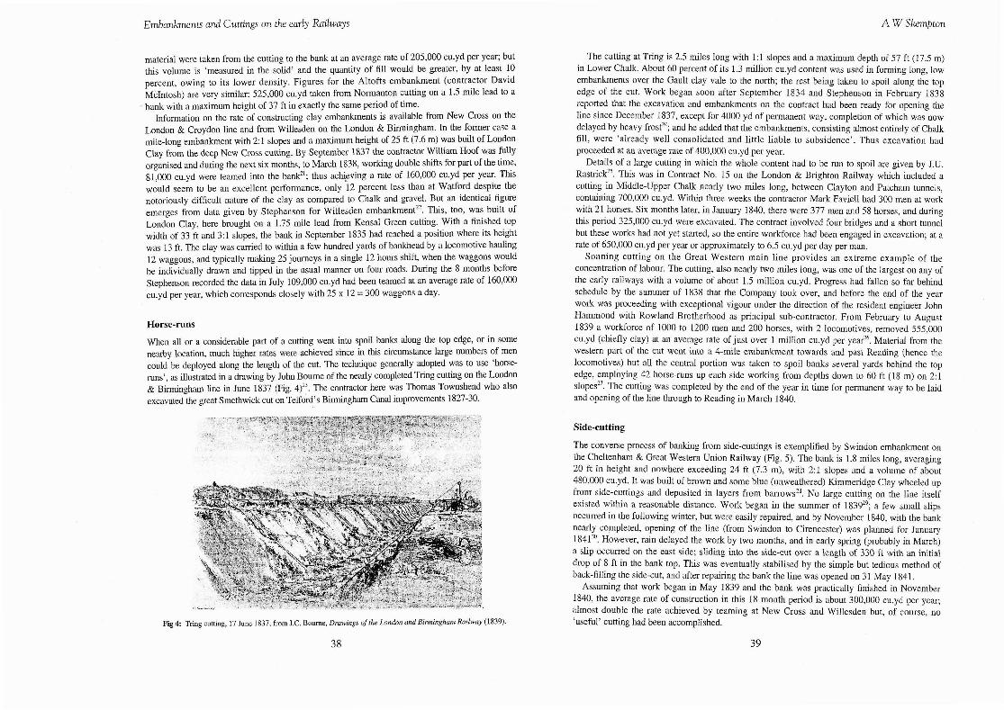
When all or a considerable part of a cutting went into spoil banks along the top edge, or in some nearby location, much higher rates were achieved since in this circumstance large numbers of men could be deployed along the length of the cut. The technique generally adopted was to use 'horse- runs', as illustrated in a drawing by John Bourne of the nearly completed Tring cutting on the London & Birmingham line in June 1837 (Fig. 4)';. The contractor here was Thomas Townshend who also excavated the great Smethwick cut on Telford's Birmingham Canal improvements 1827-30.
Fig 4: Tring cutting, 17 June 1837, from J.C. Bourne, Drawings of the London and Birmingham Railway (1839).
3 8
The cutting at Tring is 2.5 miles long with 1:l slopes and a maximum depth of 57 ft (17.5 m) in Lower Chalk. About 60 percent of its 1.3 million cu.yd content was used in forming long, low embankments over the Gault clay vale to the north; the rest being taken to spoil along the top edge of the cut. Work began soon after September 1834 and Stephenson in February 1838 reported that the excavation and embankments on the contract had been ready for opening the line since December 1837, except for 4000 yd of permanent way, completion of which was now delayed by heavy frostz; and he added that the embankments, consisting almost entirely of Chalk fill, were 'already well consolidated and little liable to subsidence'. Thus excavation had proceeded at an average rate of 400,000 cu.yd per year.
Details of a large cutting in which the whole content had to be run to spoil are given by J.U. as tick^^. This was in Contract No. 15 on the London & Brighton Railway which included a cutting in Middle-Upper Chalk nearly two miles long, between Clayton and Patcham tunnels, containing 700,000 cu.yd. Within three weeks the contractor Mark Faviell had 300 men at work with 21 horses. Six months later, in January 1840, there were 377 men and 58 horses, and during this period 325,000 cu.yd were excavated. The contract involved four bridges and a short tunnel but these works had not yet started, so the entire workforce had been engaged in excavation; at a rate of 650,000 co.yd per year or approximately to 6.5 cu.yd per day per man.
Sonning cutting on the Great Western main line provides an extreme example of the concentration of labour. The cutting, also nearly two miles long, was one of the largest on any of the early railways with a volume of about 1.5 million cu.yd. Progress had fallen so far behind schedule by the summer of 1838 that the Company took over, and before the end of the year work was proceeding with exceptional vigour under the direction of the resident engineer John Hammond with Rowland Brotherhood as principal sub-contractor. From February to August 1839 a workforce of 1000 to 1200 men and 200 horses, with 2 locomotives, removed 555,000 cu.yd (chiefly clay) at an average rate of just over 1 million cu.yd per yed6 . Material from the western part of the cut went into a 4-mile embankment towards and past Reading (hence the locomotives) but all the central portion was taken to spoil banks several yards behind the top edge, employing 42 horse-runs up each side working from depths down to 60 ft (18 m) on 2:l slopesz7. The cutting was completed by the end of the year in time for permanent way to be laid and opening of the line through to Reading in March 1840.
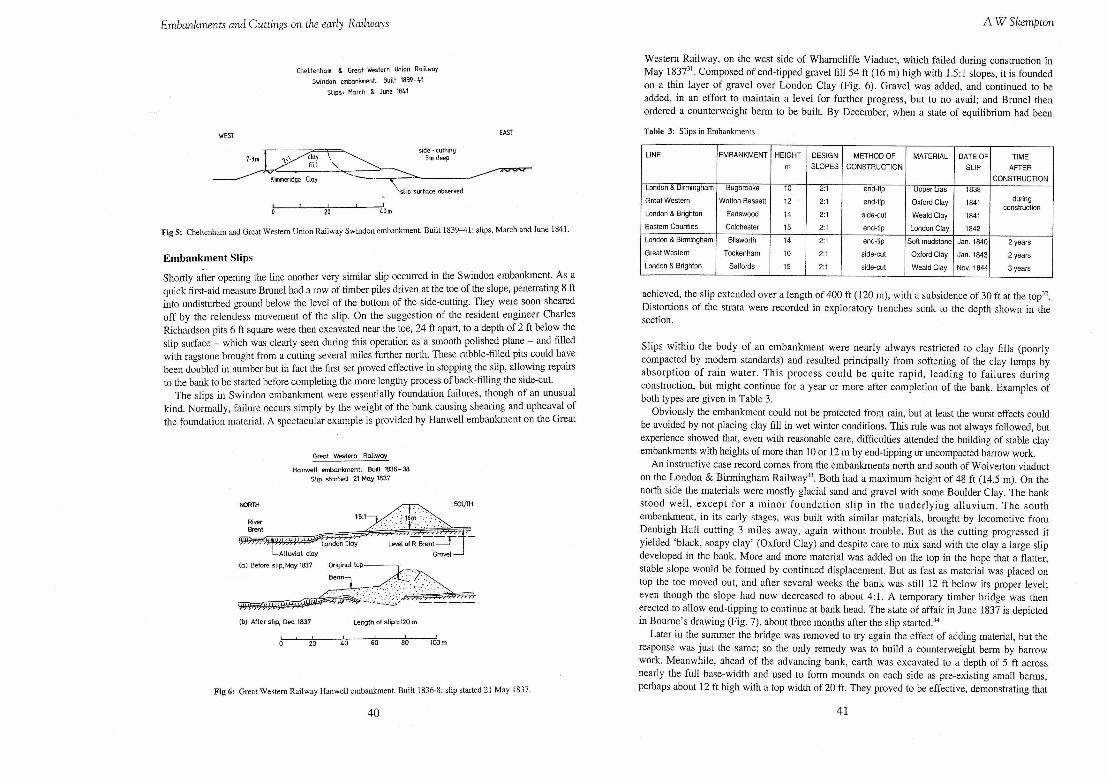
The converse process of banking from side-cuttings is exemplified by Swindon embankment on the Cheltenham & Great Western Union Railway (Fig. 5). The bank is 1.8 miles long, averaging 20 ft in height and nowhere exceeding 24 ft (7.3 m), with 2:1 slopes and a volume of about 480,000 cu.yd. It was built of brown and some blue (unweathered) Kimmeridge Clay wheeled up from side-cuttings and deposited in layers from barrowsz8. No large cutting on the line itself existed within a reasonable distance. Work began in the summer of 183929; a few small slips occurred in the following winter, but were easily repaired, and by November 1840, with the bank nearly completed, opening of the line (from Swindon to Cirencester) was planned for January 18413'. However, rain delayed the work by two months, and in early spring (probably in March) a slip occurred on the east side; sliding into the side-cut over a length of 330 ft with an initial drop of 8 ft in the bank top. This was eventually stabilised by the simple but tedious method of back-filling the side-cut, and after repairing the bank the line was opened on 31 May 1841.
Assuming that work began in May 1839 and the bank was practically finished in November 1840, the average rate of construction in this 18 month period 1s about 300,000 cn.yd per year; almost double the rate achieved by teaming at New Cross and Willesdeu but, of course, no 'useful' cutting had been accomplished.
Embankments and Cuttings on the early Railways A W Skempton
Cheltenhom & Greot Western Union Railway
Svtndon embankment. h i l t 1839-41 Slips. March & June 1841
WEST EAST
side - cutttng 3m deep
H
Kimmeridge Cloy
face observed /
Fig 5: Cheltenham and Grest Western U n ~ o n Ralway Sw~ndon embankment. B u ~ l t 1839-41: shps, March and June 1841
Embankment Slips
Shortly after opening the line another very similar slip occurred in the Swindon embankment. As a quick first-aid measure Brunel had a row of timber piles driven at the toe of the slope, penetrating 8 ft into undisturbed ground below the level of the bonom of the side-cutting. They were soon sheared off by the relentless movement of the slip. On the suggestion of the resident engineer Charles Richardson pits 6 ft square were then excavated near the toe, 24 ft apart, to a depth of 2 ft below the slip surface - which was clearly seen during this operation as a smooth polished plane - and filled with ragstone brought from a cutting several miles further north. These rubble-filled pits could have been doubled in number but in fact the first set proved effective in stopping the slip, allowing repairs to the bank to be started before completing the more lengthy process of back-filling the side-cut.
The slips in Swindon embankment were essentially foundation failures, though of an unusual kind. Normally, failure occurs simply by the weight of the bank causing shearing and upheaval of the foundation material. A spectacular example is provided by Hanwell embankment on the Great
Great Westwn Railway
Hanwell wnbankrnent. Built W36-38 Slip started 21 May 1837
NORTH
(b) After slip, Dec 1837 Length of slip=120 rn
I 20 40 60 80 ICQrn
Fig 6: Great Western Railway Hanwell embankment. Bui l t 1836-8: slip started 21 May 1837.
Western Railway, on the west side of Wharncliffe Viaduct, which failed during construction in May 1837~'. Composed of end-tipped gravel fill 54 ft (16 m) high with 1.5:l slopes, it is founded on a thin layer of gravel over London Clay (Fig. 6). Gravel was added, and continued to be added, in an effort to maintain a level for further progress, but to no avail; and Brunel then ordered a counterweight berm to be built. By December, when a state of equilibrium had been
Table 3: Slips in Embankments
LINE
- London & Birmingham
Great Western
London & Brighton
MATERIAL
Eastern Count~es
achieved, the slip extended over a length of 400 ft (120 m), with a subsidence of 30 ft at the top3'. Distortions of the strata were recorded in exploratory trenches sunk to the depth shown in the section.
Bugbrooke
Wotton Bassett
Earlswood
Great Western
London & Brighton
Slips within the body of an embankment were nearly always restricted to clay fills (poorly compacted by modem standards) and resulted principally from softening of the clay lumps by absorption of rain water. This process could be quite rapid, leading to failures during construction, but might continue for a year or more after completion of the bank. Examples of both types are given in Table 3.
DATE OF
SLIP
Colchester
Obviously the embankment could not be protected from rain, but at least the worst effects could be avoided by not placing clay fill in wet winter conditions. This rule was not always followed, but experience showed that, even with reasonable care, difficulties attended the building of stable clay embankments with heights of more than 10 or 12 m by end-tipping or uncompacted barrow work.
An instructive case record comes from the embankments north and south of Wolverton viaduct on the London & Birmingham Railway33. Both had a maximum height of 48 ft (14.5 m). On the north side the materials were mostly glacial sand and gravel with some Boulder Clay. The bank stood well, except for a minor foundation slip in the underlying alluvium. The south embankment, in its early stages, was built with similar materials, brought by locomotive from Denbigh Hall cutting 3 miles away, again withoot trouble. But as the cutting progressed it yielded 'black, soapy clay' (Oxford Clay) and despite care to mix sand with the clay a large slip developed in the bank. More and more material was added on the top in the hope that a flatter, stable slope would be formed by continued displacement. But as fast as material was placed on top the toe moved out, and after several weeks the bank was still 12 ft below its proper level; even though the slope had now decreased to about 4:l. A temporary timber bridge was then erected to allow end-tipping to continue at bank head. The state of affair in June 1837 is depicted in Bourne's drawing (Fig. 7), about three months after the slip started.34
Later in the summer the bridge was removed to try again the effect of adding material, but the response was just the same; so the only remedy was to build a counterweight berm by barrow work. Meanwhile, ahead of the advancing bank, earth was excavated to a depth of 5 ft across nearly the full base-width and used to form mounds on each side as pre-existing small berms, perhaps about 12 ft high with a top width of 20 ft. They proved to be effective, demonstrating that
TIME
AFTER
10
12
14
London & Birmingham
Tockenham
Salfords
15
2 1
2:l
2 1
Bliswolth
10
15
2:1
end-tip
end-tip
side-cut
14
2:1
2 1
end-tip
2:1 / end-tip (~oflmudstoneI Jan. 18401 2 years
Upper Lias
Oxford Clay
Weald Clay
side-cut
side-cut
London Clay
1838
1841
1841
1842
Oxford Clay
Weald Clay
CONSTRUCTION
c o ~ ~ ~ ~ i o n
Jan. 1843
Nov. 1844
2 years
3 years
Embankments and Cuttings on the early Railways A W Skempton
London & Croydon Railway
New Cross Cutting. Excavated 1837-38
WEST EAST
Fig 7: Wolverton embankment, 28 June 1838, from J.C. Bourne, Drawings of the Lonrlon and Birmingham Railway (1839).
it is easier to prevent a slip than to stabilise one after it has occurred. This is due to the fact that the 'residual' strength on a slip surface is much smaller than the strength of the unsheared clay35. In February 1838 Stephenson reported that work at Wolverton had for some time been advancing in the most satisfactory manner, and would be completed in eight weeks time, as indeed it was.36 The very flat slope required for final stability after a slip in clay fill is illustrated by Colchester embankment on the Eastern Counties Railway. Two slips totalling 380 ft (115 m) in length developed during construction of this end-tipped 50 ft (15 m) high London Clay embankment, in the autumn of 1842. Material was added on the top, as usual, bot in this case the process was continued until stability had been achieved, by outward displacement of the toe, with a slope of 6:13'; an operation in which 34,000 cu.yd of additional fill was 'swallowed up'38. Trestle bridges were then built across the top, still much below its proper level, and the hank left to consolidate until July 1843, when it was completed without further slipping39.
Slips in Clay Cuttings
Superficial slips were common in clay cuttings (and embankments) either in rainy seasons during construction or in the first or second winter afterwards. They usually required for their repair no more than trimming and a few shallow trench drains. In an altogether different category were deep slips which took place, almost without warning, several years after excavation. Three well- documented cases are summarised in Table 4.
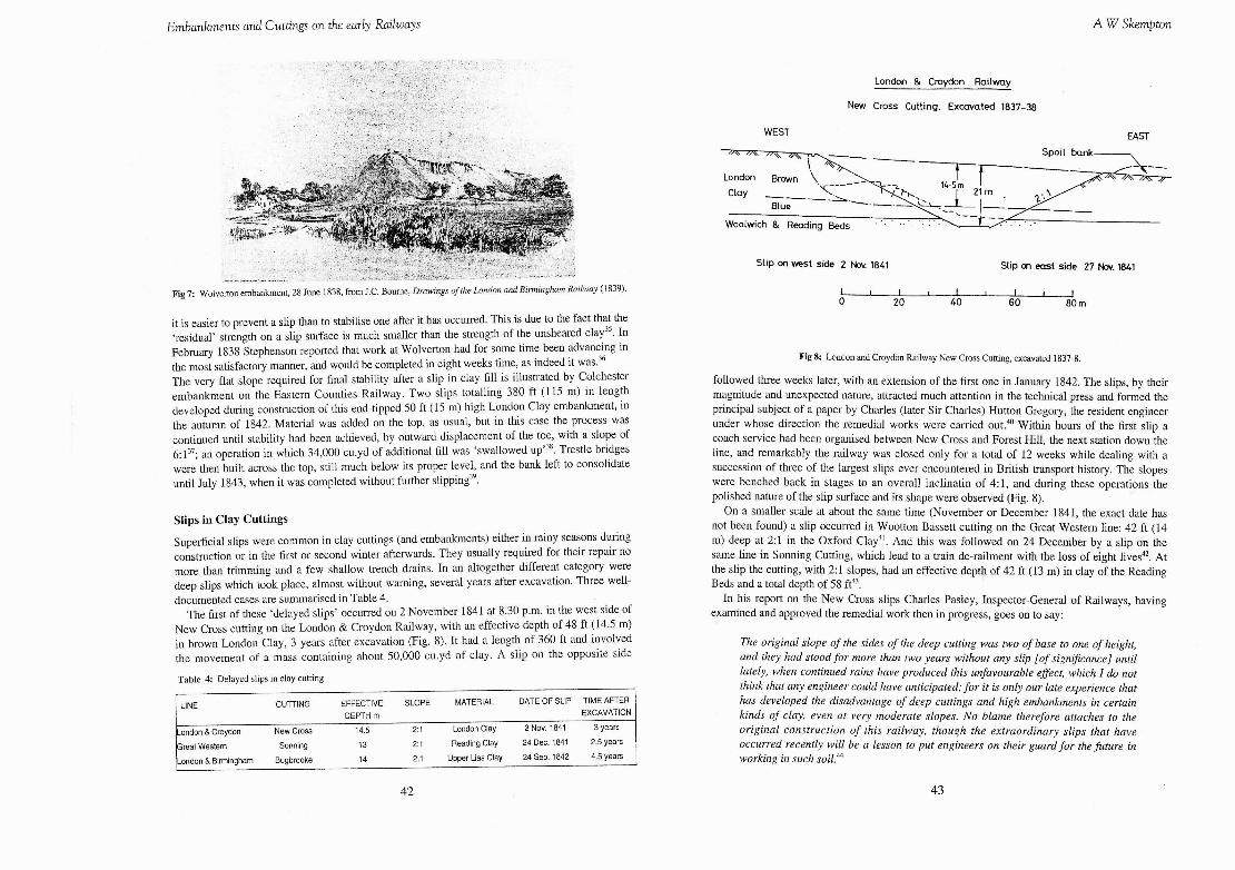
The first of these 'delayed slips' occurred on 2 November 1841 at 8.30 p.m. in the west side of New Cross cutting on the London & Croydon Railway, with an effective depth of 48 ft (14.5 m) in brown London Clay, 3 years after excavation (Fig. 8). It had a length of 360 ft and involved the movement of a mass containing about 50,000 cu.yd of clay. A slip on the opposite side
Table 4: Delayed slips in clay cutting -
LINE CUTTING EFFECTIVE SLOPE MATERIAL DATE OF SLIP TIME AFTER DEPTH m EXCAVATION
London & Croydon New Cross 14.5 2:l London Clay 2 Nov. 1841 3 years
Great Western Sonning 13 2:l Reading Clay 24 Dec. 1841 2.5 years
London & Birmingham Bugbrooke 14 2:l Upper Lias Clay 24 Sep. 1842 4.5 yean
London
Clav I 21 rn
Slip on west side 2 W. 1841 Slip on east side 27 b. 1841
Fig 8: London and Croydon Railway New Cross Cutting, excavated 1837-8
followed three weeks later, with an extension of the first one in January 1842. The slips, by their magnitude and unexpected nature, attracted much attention in the technical press and formed the principal subject of a paper by Charles (later Sir Charles) Hutton Gregory, the resident engineer under whose direction the remedial works were camed out.40 Within hours of the first slip a coach service had been organised between New Cross and Forest Hill, the next station down the line, and remarkably the railway was closed only for a total of 12 weeks while dealing with a succession of three of the largest slips ever encountered in British transport history. The slopes were benched back in stages to an overall inclinatin of 4:1, and during these operations the polished nature of the slip surface and its shape were observed (Fig. 8).
On a smaller scale at about the same time (November or December 1841, the exact date has not been found) a slip occurred in Wootton Bassett cutting on the Great Western line: 42 ft (14 m) deep at 2:l in the Oxford Clay4'. And this was followed on 24 December by a slip on the same line in Sonning Cutting, which lead to a train de-railment with the loss of eight lives". At the slip the cutting, with 2: 1 slopes, had an effective depth of 42 ft (13 m) in clay of the Reading Beds and a total depth of 58 ftJ3.
In his report on the New Cross slips Charles Pasley, Inspector-General of Railways, having exarmned and approved the remedial work then in progress, goes on to say:
The original slope of the sides of the deep cutting was two of base to one of height, and they had stood for more than two years without any slip [of significance] until lately, when continued rains have produced this unfavourable effect, which I do not think that any engineer could have anticipated; for it is only our late experience that has developed the disadvantage of deep cuttings and high embankments in certain kinds of clay, even at very moderate slopes. No blame therefore attaches to the original construction of this railway, though the extraordinary slips that have occurred recently will be a lesson to put engineers on their guard for the future in working in such soiLM

Embankments and Cuttings on the early Railways A W Skempton
London 8 Birmingham Railway
Bugbrooke Cutting. Excavated 1835 -37
Slip 24 Sept. 1842
SOUW WEST NORM EAST
appmxirnate dip surface
Fig 9: London and Birmingham Railway Bugbrooke Cutting. Excavated 1835-7: slip 24 September 1842.
Thus, while Pasley emphasises the delayed nature of the slips (and he had in mind Sonning as well as New Cross) he attributes their occurrence to heavy rain; an opinion generally held at the time.
In the sense that rain can trigger a slip, this is true. But in h s 1844 paper Gregory postulated that additionally a more fundamental process must be involved: deep-seated progressive softening of the clay, connected in some way with the effects of stress release caused by excavation, and he thought that the fissured nature of London Clay played a significant role. This foreshadows the explanation of delayed slips in stiff fissured clays put forward by Terzaghi in 193645, from which stemmed a long series of investigations leading, very recently, to a proper understanding of the complex process of pore pressure change and progressive failure involved46.
The early winter of 1841, however, was indeed exceptionally wet. But in September 1842 a slip occurred on the London & Birmingham line at a time of only moderate rainfall and in a cutting which had remained stable for more than 4 years. This was at Bugbrooke, in Northamptonshire: a cutting 47 ft (14.3 m) deep with 2:l slopes in Upper Lias clay (Fig. 9) completed before February 1838 and which had survived the winter of 1841-42 (and, like Sonning and New Cross, the scarcely less wet winter of 1839-40).
The circumstances are described by Pasley who now realised that some deep-seated effect must be acting, and he began to wonder if deep cuttings in 'London Clay and other plastic clay formations' were always liable to slip sooner or later.47 Subsequent experience has shown this view to be not far from the truth. Cuttings with slopes steeper than 3.5:l in London Clay or 2.5:l in Upper Lias clay, for example, are prone to slip 10 to 50 years (or even longer) after excava t i~n~~.
While developing his ideas on delayed slips Gregory would no doubt have been influenced by the failure at Bugbrooke, and also by further slips on the Croydon line sonth of New Cross, in cuttings at Brockley (9 m deep) and Forest Hill (12 m deep): both in brown London Clay.
Remedial Measures
The usual method of stabilising a deep clay slip on the early railways was to flatten the slope, either by trimming or benching back, or in extreme cases by removing the slip mass G = gravel counterfort 5 = back of slip
entirely, as at New Cross. F = gravel foot~ng T = top o f slope
Slope flattening required the removal of considerable volumes of clay (25,000 cu.yd at Wotton Bassett) and the purchase of land outside this existing boundary fence (nearly an acre at Bugbrooke, 1.7 acres at Forest Hill).
Counterforts were an
Plon and section of counterforts,
redrawn from a sketch by Gregory IlBLLl
alternative remedial Fig 10: Plan and section of counterforts, redrawn from a sketch by C.H. Gregory,
measure, except perhaps Min. Proc. Insti. ofCiv. Ene. 3 (1844). " ~ , for very large slips. They consist of trenches, typically 6 ft wide at 24 ft centres, dug into the slope to a depth of 2 or 3 ft below the slip surface and backfilled with gravel or rubble stone rammed in tight (Fig. 10) and act both as an internal buttress and as a deep drain. Introduced by Robert Stephenson in 1839 to stabilise the Jurassic clay slopes above the limestone in Blisworth cutting49, counterforts were used by Joseph Locke early in 1842 in the cuttings adjacent to Tapnage tunnel on the Gosport Branch of the London & South Western ailw way" and later that year by Gregory in Brockley cutting. At Tapnage the slips occurred within a year of excavation; not surprisingly, as the cuttings were made at 1.5:l in London Clay! In this case the slopes were cut back before installing the counterforts.
It appears that Gregory in 1844 gives the first published description of counterforts, though by that time they were quite well known; as clearly emerges from the discussion on his paper. They became practically a standard remedial measure on the jailways, and remained so for the next hundred years.
Note on Steam Power
It has been mentioned above that stationary engines were sometimes used on earthworks. An example is provided by the cutting (600,000 cu.yd) and embankment (430,000 cu.yd) at Leire on the Midland Counties Railway. This was part of a big contract carried out by David McIntosh on the 20 miles length between Leicester and Rugby. In the summer of 1838 on this contract he had nearly 2000 men at work with about 150 horses, and as the engineer Thomas Woodhouse reports:
The spirited manner in which Mr Macintosh is working his heaviest cuttings, shows his determination to complete the works in the time speci$ed in his contract, the 1st

Embankments and Cuttings on the early Railways A W Skempton
of May 1840 ... The excavation at Leir Hill is the most extensive piece of earthwork on the whole line of railway; and here he is erecting a steam-engine to facilitate his operations; he has an inclined plane from the cutting to the embankment (on a lead of 0.75 miles) where the material is to be deposited. The plane descends at an angle just sufficient for the gravity of the waggons to overcome their friction and the resistance offered by the rope. The waggons, when emptied, are drawn back by the engine; by this means, more earth may be removed expeditiously than by any other yet practised.50
McIntosh continued with great vigour, his workforce by the following year having increased to 2600 men and 260 horses, and despite the wet winter of 1839-40 he managed to complete the whole contract, involving upwards of 3 million cu.yd of excavation as well as the Avon viaduct, at the specified time after 2.5 years work; thus averaging at least 240,000 cu.yd per year in the Leire cutting, practically the full depth of 60 ft (18 m) being in Boulder Clays1. The embankment, with 2:l slopes and a maximum height of 40 ft (12 m), was already well consolidated on opening the line in July 1840 and there is no record of any slips in the bank5'.
Other than a fairly restricted application of stationary engines the sole use of steam power for excavation on the early British railways was on the Eastern Counties line when John Braithwaite in 1843 canied out successful trials of the 'American Steam Excavator'. Powered by a 10 h.p. (nominal) engine, this was the fourth machine of its kind made by Camichael, Fairbanks & Otis and used from 1838 on the Western Railroad (from Worcester, Mass. to Albany, N.Y.). It dug and loaded into waggons about 500 cu.yd of sand per day: equivalent to the work of rather more than 30 men, and at roughly half the costS3. Nevertheless, even in America, where labour was less plentiful, steam navvies came into their own only so late as the 1880s with the introduction of far more powerful machinerys4. In England they were first used on a grand scale on the Manchester Ship Canal (1887-93) where 58 large and 17 smaller steam navvies excavated 54 million cu.yd in 6 yearss5.
Conclusions
Cuttings and embankments on the early railways were planned on the principle of designing for normal, expected conditions and dealing with the abnormal when it is encountered. Slips, in the latter category, gave a lot of trouble but mostly in deep clay cuttings and high embankments where previous experience scarcely existed. They should be seen in relation to the great majority of the earthwork which was carried out rapidly and successfully on an unprecedented scale by the methods and with the results described.
Correspondence. Prof. A.W. Skempton. Department of Civil Engineering, Imperial College, London, SW7 2BU.
References
1 L.T.C. Rolt, The London-Birmingham Motorway [1960]. For the Great Central Railway see papers by F.W. Bidder and F.D. Fox Min. Proc. Inst. Civ. Eng. 142 (1900), pp. 1-48. Data on the early railways come from half-yearly reports supplemented in some cases by information from Francis Whishaw, The Railways of Great Britain (1842).
2. Details of the London & Binningham Railway workforce have not been found, except that the numbers of men employed were upwards of 10,000 in July 1836 and 12,000 in June
1837; as reported in Railway Magazine. 3. Peter Lecount, The Histoly of The Railway Connecting London & Birmingham (1839) p. 42.
Quantities are given by Arthur Freeling, The Railway Companion from London to Birmingham, Liverpool & Manchester (1828) p. 12 and sections of the cutting by F.W. Simms, Public Works of Great Britain (1838), pls. 20-35.
4. Civil Engineer & Architect's Journal 2 (1839), pp. 224-225. In a note on p. 252 R.B. Dockray says this method was in full operation before he took up his post as resident engineer (in December 1835) on this section of the line.
5. The specification, dated August 1836, is quoted in S.C. Brees Railway Practice (1837) pp. 93-108. Macneill worked from 1826 under Telford on the London-Shrewsbury division of the Holyhead road; his specification for the Salamannan embankments may reflect this experience.
6. For example, Robert Stephenson specifies layes not exceeding 3 ft in thickness, each being 'closely packed' previous to succeding layers being laid on, for a viaduct on the Slatley contract, London & Birmingham Railway, 1834. Townshend collection, Inst. Civ. Eng. archives. See also Vignoles' specification of 1836 for the Avon viaduct on the Midland Counties Railway in Brees pp. 85-86.
7. "Resident Assistant Engineer" (J.D. Hughes), A Practical Inquiry into The Laws of Excavations and Embankments upon Railways (1840) pl. 1 (see Fig.1) and pp. 163-165. Details of end-tip waggons are given by "O.T." "On Earthworks, Excavation, Cutting and Embankment upon Railways", Civil Engineer & Architect's Journal 6 (1843) pp. 265-268 (see Fig.2) and by G. Drysdale Dempsey, Railways, Papers on the mechanical and engineering operations and structures combined in the making of a railway, (1846) pl. 9.
8. Dempsey pl. 5 shows an embankment under construction with 4 roads at the bankhead; this seems to have been the most usual arrangement.
9. These figures were widely accepted, and often quoted in, for example, The Minutes of Evidence of Parliamentary Committeees.
10. L.T.C. Rolt, George and Robert Stephenson (1960) p. 71. For heights of the embankments see Railways in England I826 and 1827, Translation from the German (Berlin, 1829), published for the Newcomen Society (Cambridge, 1971).
11. R.E. Carlson, The Liverpool & Manchester Railway Project, 1821-1831 (Newton Abbot, 1969) pp. 188-192.
12. Thomas Telford, Liverpool & Manchester Railway. Report to the Commissioners for the Loan of Exchequer Bills (1 829).
13. Joseph Locke, Minutes of Evidence, London & Southampton Bill, 19 June 1834. 14. Robert Stephenson, ibid., 25 June 1834. 15. I.K. Bmnel, Minutes of Evidence, London & ~ r i ~ h t o h Bill, 7 March 1837. 16. The Watford contract was let in May 1834 but work on the cuttings and embankments
probably started not before August, as the earth waggons were built on site while digging foundation pits for the viaduct and sinking shafts for the tunnel. Completion of the tunnel and embankment is recorded in the April 1837 issue of Railway Magazine. Freeling Railway Companion gives volumes of the embankment and adjacent cuttings.
17. G.W. Buck, Minutes of Evidence, Great Western Bill, 7 July 1835. 18. James Copeland, ibid. 19. Robert Stephenson, Minutes of Evidence, London & Brighton Bill, 8 July 1836. 20. F. Swanwick, Reports on the North Midland Railway, Railway Magazine, (Febmary 1839
and Febmary 1840). This journal in November 1837 reports that operations had commenced in the Wakefield district where considerable numbers of workmen are already employed.
21. Half-yearly reports on the Croydon Railway, including data supplied by the engineer Joseph
47

Embankments and Cuttings on the early Railways A W Skempton
Gibbs, Railway Magazine, (March and September 1837; March 1837). 22. Robert Stephenson, Minutes of Evidence, Great Western Bill, 8 July 1835. 23. John C. Bourne, Drawings of the London and Birmingham Railway (1839), pl. 19. An
'interesting variant was introduced by the contractor James & George Thornton in the Haywards Heath cutting on the London & Brighton line. This operated like a cliff railway with a frame carrying three loaded barrows being hauled up the steep slope on an inclined plane while another, unloaded, descended. See Railway Magazine (27 March 1841).
24. This information is given in Robert Stephenson's report, dated 17 Feb 1838, printed in Railway Times.
25. J.U. Rastrick, Half-yearly reports on the London & Brighton Railway, Railway Magazine (July 1839 and January 1840).
26. Half-yearly reports on the Great Western ~ a i l w a ~ , Railway Times (August 1838, February and August 1839).
27. S.A. Leleux, Brotherhoods, Engineers (Dawlish, 1965), p. 11. 28. C.W. Pasley,'Report on the present state of the Swindon embankment', 14 Jan 1842:
Reports of the Railway Department, 1842, pp. 91-92. 29. Much of the information on Swindon embankment is given by the resident engineer Charles
Richardson in a paper published as a separate pamphlet On Landslips. (Bristol, 1891). 30. I.K. Brunel. Half-yearly reports on the Cheltenham & Great Western Union Railway,
Railway Magazine ( 3 Nov 1840 and 4 May 1841). 31. Joseph Colthurst, discussion on the paper by C.H. Gregory Min. Proc. Inst. Civ. Eng. 3,
(1844) pp. 163-166. 32. Railway Magazine (January 1838), p. 65. 33. Lecount, p. 37. 34. Bourne, pl. 23. 35. A.W. Skempton,'Residual strength of clays', Geotechnique 35 (1985), pp. 3-18. 36. Robert Stephenson, Report on the London & Binningham Railway., Railway Times (17 Feb
1838). 37. Peter Bruff, discussion on the paper by C.H. Gregory Min. Proc. Inst. Civ. Eng. 3, (1844) p.
147. 38. John Braithwaite, Report on the Eastern Counties Railway, Railway Times (27 Oct 1842). 39. C.W. Pasley, Reports on the Extension of the Eastern Counties Railway from Brentwood to
Colchester, 14 March 1843 and 29 July 1843: Reports of the Railway Department, 1843, pp. 150-153.
40. C.H. Gregory, "On Railway Cuttings and Embankments; with an account of some slips in London clay, on the line of the London to Croydon Railway" Min. Proc. Inst. Civ. Eng. 3, (1844). The paper was presented on 26 March 1844. The lengthy discussion includes several valuable contributions.
41. I.K. Brunel, Half-yearly reports on the Great Western Railway, Railway Times (22 Feb 1842).
42. Sir Frederic Smith, 'Report on the accident on the Great Western Railway on the morning of the 24th December 1841'. 25 December 1841: Reports of the Railway Department. 1842, pp. 77-79.
43. Joseph Colthurst, discussion on paper by C.H. Gregory Min Proc Inst. Civ. Eng. 3 (1844) pp. 167-168, including a section of Sonning cutting with a sketch of the slip surface.
44. C.W. Pasley, 'Report on the recent slip on the Croydon Railway, near New Cross', 12 Jan 1842. Reports of the Railway Department. 1842, pp. 92-93.
45. K. Terzaghi, 'Stability of slopes in natural clay', Proc. Int. Conf: Soil Mechanics (1936) 1 pp. 161-165.
46. P.R. Vaughan. 'Assumption, prediction and reality in geotechnical engineering'. Geotechnique, 44 (1994), pp. 573-609.
47. C.W. Pasley, 'Report on the slip of earth in the Bugbrook cutting . . . with observations on embankments and cuttings' 20 Sept 1842. Reports of the Railway Department, 1843, pp 225-226.
48. R.J. Chandler & A.W. Skempton,'The design of permanent cuttings slopes in stiff fissured clays', Geotechnique, 24 (1974), pp. 437-466.
49. R.B. Dockray, discussion on the paper by Gregory Min. Proc. Insti. Civil Eng. 3 (1844) pp. 148-150. He adds that counterforts since their introduction about 5 years ago have been 'extensively' used in repairing slips on the London & Birmingham Railway. Counterforts of solid masonry, acting solely as internal buttresses, were used in 1833 to stabilise the slopes of Panthier earth dam on the Canal de Bourgogne, and similarly in 1835 in Cercey dam, (Alexandre Collin Recherches expe'rimentales sur les Glissements des Terrains Argileux, Paris, 1846). Gravel counterforts in English railway earthworks constituted an independent development; they appear to have been unknown to the earlier canal engineers.
50. C.W. Pasley,'Report on the proposed opening of the Gosport Branch of the London & South Western Railway', 5 Feb. 1842: Reports of the Railway Department 1843, pp. 171-172. Locke and the contractor Thomas Brassey ran into all kinds of trouble on the short length of this line between Botley and Fareham: slips in Fontley embankment and Tapnage cutting, and the collapse of Fareham tunnel (in the Reading Beds) when nearing completion in July 1841.
51. T.J. Woodhouse, Progress report on the Midland Counties Railway, Railway Times (June 1838).
52. General meeting of the Midland Counties Railway, Railway Magazine (Aug. 1840). It should be noted that about 25 percent of the Leire excavation was taken to spoil.
53. Civil Engineer & Architect's Journal 6 (1843), pp 268-269. This article includes an engraving of the Steam Excavator. Its bucket held 1.25 cu.yd.
54. Russell Jones, 'A history of civil engineering plant', New Civil Engineer 9 Nov. 1978, pp. 37-105.
55. Sir Edward Leader Williams. 'The Manchester Ship Canal', Min. Proc. Inst. Civ. Eng. 131 (1897), pp. 14-30. The use of steam power reached its maximum on the Panama Canal where, between 1906 and 1915, some 130 million cu.yd of excavation was accomplished by upwards of 100 steam shovels (as they were called in America) and 160 locomotives. (G.W. Goethals, The Panama Canal, New York, 1916). In both these works, however, most of the excavated material was taken to spoil.