Embed Size (px)
Citation preview
www.garaventalift.com
ELVORON HOME ELEVATORPLANNING GUIDE
Creating An Accessible World

Please note:Dimensions provided in this Guide are for REFERENCE ONLY and should not be used for site preparation or construction.
Table of ContentsElvoron - Home Elevator ...................................................................................................................4Hoistway Construction ................................................................................................................... 5 Wood Construction ....................................................................................................................... 6 Masonry Construction ....................................................................................................................6 Door Openings .............................................................................................................................6Construction of Pit: ..........................................................................................................................7 Pit Lighting ..................................................................................................................................7 Overhead Clearance .......................................................................................................................7Car/Gate Door & Hoistway Doors .....................................................................................................8 Hoistway Door Interlock ................................................................................................................8Standard Door Package .................................................................................................................8 Automatic Cab Gate (Optional) .......................................................................................................8 Hall Door Operator (Optional) .........................................................................................................8Upgrade Door Package .................................................................................................................8 Hall Door Operator (Optional) .........................................................................................................8Premium Door Package .................................................................................................................83” & 5” Door Clearance Rule ............................................................................................................9Hoistway Dimensions - standard door package ..............................................................................10Hoistway Dimensions - upgrade door package ...............................................................................12Hoistway Dimensions - premium door package ..............................................................................143-Speed Door Details .....................................................................................................................16Hydraulic Drive System Overview: .................................................................................................17Hydraulic Drive System - Technical Reference: ..............................................................................18 General .....................................................................................................................................18 Equipment ................................................................................................................................18 Controls ....................................................................................................................................18 Safety Features .........................................................................................................................18 Options .....................................................................................................................................18Hydraulic Drive System - Machine Room & Electrical Requirements: ..............................................19 Electrical Disconnects .................................................................................................................20 Ventilation Requirements ............................................................................................................20 Mains Power Requirements ..........................................................................................................20 Lighting Power Requirements ........................................................................................................20 Emergency Battery Lowering ........................................................................................................20 Emergency Manual Lowering ........................................................................................................20Hydraulic Drive System - Machine Room Layout .............................................................................21In-line Drive System Overview ......................................................................................................22In-line Drive System - Technical Reference: ..................................................................................23 General .....................................................................................................................................23 Equipment ................................................................................................................................23 Controls ....................................................................................................................................23 Safety Features .........................................................................................................................23 Options .....................................................................................................................................23In-line Drive System - Electrical Controller Box Details & Locations ...............................................24 Electrical Disconnects .................................................................................................................25 Ventilation Requirements ............................................................................................................25 Mains Power Requirements ..........................................................................................................25 Lighting Power Requirements ........................................................................................................25 Battery Lowering - Optional .........................................................................................................25 Battery Backup - Optional ........................................................................................................... 25Emergency Lowering - Standard .....................................................................................................26Loading Diagram: ...........................................................................................................................27
Elvoron - Home Elevator
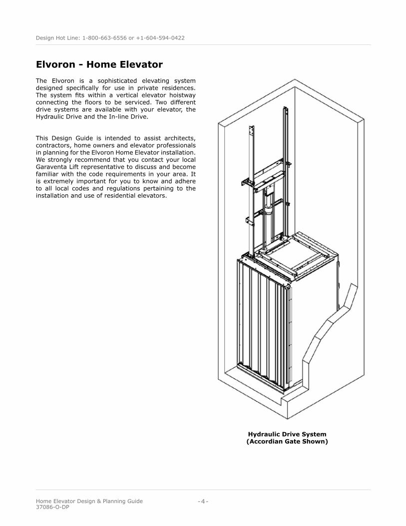
Hydraulic Drive System (Accordian Gate Shown)
The Elvoron is a sophisticated elevating system designed specifically for use in private residences. The system fits within a vertical elevator hoistway connecting the floors to be serviced. Two different drive systems are available with your elevator, the Hydraulic Drive and the In-line Drive.
This Design Guide is intended to assist architects, contractors, home owners and elevator professionals in planning for the Elvoron Home Elevator installation. We strongly recommend that you contact your local Garaventa Lift representative to discuss and become familiar with the code requirements in your area. It is extremely important for you to know and adhere to all local codes and regulations pertaining to the installation and use of residential elevators.
-4-
Design Hot Line: 1-800-663-6556 or +1-604-594-0422
Home Elevator Design & Planning Guide 37086-O-DP
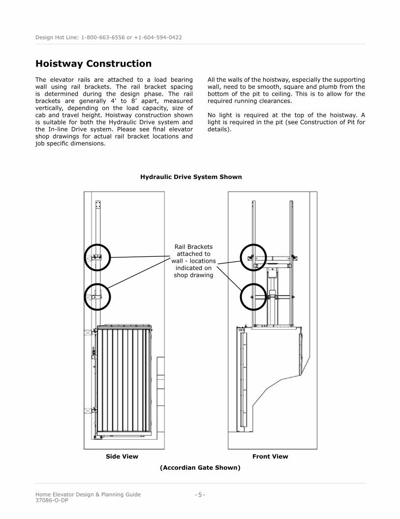
The elevator rails are attached to a load bearing wall using rail brackets. The rail bracket spacing is determined during the design phase. The rail brackets are generally 4’ to 8’ apart, measured vertically, depending on the load capacity, size of cab and travel height. Hoistway construction shown is suitable for both the Hydraulic Drive system and the In-line Drive system. Please see final elevator shop drawings for actual rail bracket locations and job specific dimensions.
Hoistway Construction
Hydraulic Drive System Shown
Side View Front View
Rail Brackets attached to
wall - locations indicated on shop drawing
All the walls of the hoistway, especially the supporting wall, need to be smooth, square and plumb from the bottom of the pit to ceiling. This is to allow for the required running clearances.
No light is required at the top of the hoistway. A light is required in the pit (see Construction of Pit for details).
(Accordian Gate Shown)
-5-
Design Hot Line: 1-800-663-6556 or +1-604-594-0422
Home Elevator Design & Planning Guide 37086-O-DP
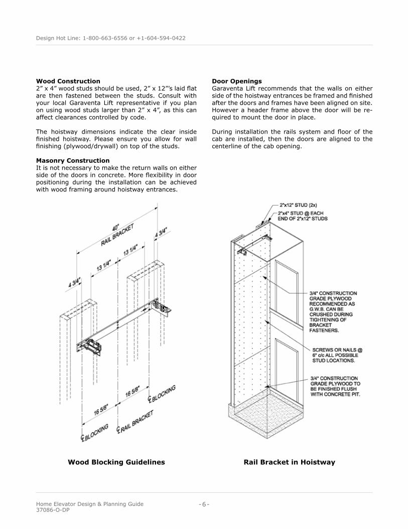
Wood Construction 2” x 4” wood studs should be used, 2” x 12”’s laid flat are then fastened between the studs. Consult with your local Garaventa Lift representative if you plan on using wood studs larger than 2” x 4”, as this can affect clearances controlled by code.
The hoistway dimensions indicate the clear inside finished hoistway. Please ensure you allow for wall finishing (plywood/drywall) on top of the studs.
Masonry Construction It is not necessary to make the return walls on either side of the doors in concrete. More flexibility in door positioning during the installation can be achieved with wood framing around hoistway entrances.
Wood Blocking Guidelines Rail Bracket in Hoistway
Door Openings Garaventa Lift recommends that the walls on either side of the hoistway entrances be framed and finished after the doors and frames have been aligned on site. However a header frame above the door will be re-quired to mount the door in place.
During installation the rails system and floor of the cab are installed, then the doors are aligned to the centerline of the cab opening.
-6-
Design Hot Line: 1-800-663-6556 or +1-604-594-0422
Home Elevator Design & Planning Guide 37086-O-DP
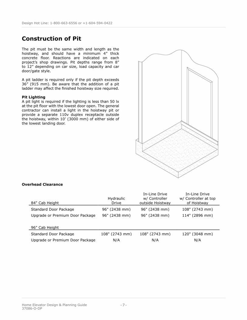
The pit must be the same width and length as the hoistway, and should have a minimum 4” thick concrete floor. Reactions are indicated on each project’s shop drawings. Pit depths range from 8” to 12” depending on car size, load capacity and car door/gate style.
A pit ladder is required only if the pit depth exceeds 36” (915 mm). Be aware that the addition of a pit ladder may affect the finished hoistway size required.
Pit LightingA pit light is required if the lighting is less than 50 lx at the pit floor with the lowest door open. The general contractor can install a light in the hoistway pit or provide a separate 110v duplex receptacle outside the hoistway, within 10’ (3000 mm) of either side of the lowest landing door.
Overhead Clearance
Construction of Pit
84" Cab HeightHydraulic
Drive
In-Line Drivew/ Controller
outside Hoistway
In-Line Drivew/ Controller at top
of Hoistway
Standard Door Package 96" (2438 mm) 96" (2438 mm) 108" (2743 mm)Upgrade or Premium Door Package 96" (2438 mm) 96" (2438 mm) 114" (2896 mm)
96" Cab Height
Standard Door Package 108" (2743 mm) 108" (2743 mm) 120" (3048 mm)Upgrade or Premium Door Package N/A N/A N/A
-7-
Design Hot Line: 1-800-663-6556 or +1-604-594-0422
Home Elevator Design & Planning Guide 37086-O-DP
Car Gate/Door & Hoistway DoorsHoistway Door Interlocks All hoistway doors are fitted with an interlock that ensures the car can not be moved from a landing unless the hall door is closed and locked.
Standard Door PackageThe Standard Door Package includes a swinging hall door by others and an accordion car gate. Residential solid core doors must be used as the hoistway doors. The doors are equipped with an electrical interlock during installation. This lock prevents the doors from opening when the elevator is not present. Recommended door width is 36”. The minimum door thickness is 1-3/4”.
Swinging hall doors must comply with local elevator codes which reference the positioning of doors in relation to the elevator hoistway and cab. (see drawings on page 9).
Automatic Cab Gate (Optional)The cab gate(s) can be equipped with a power operator for automatic gate opening and closing when the cab arrives at a landing or the landing door is opened.
Hall Door Operator (Optional)Each hall door may be supplied with a power door operator. This feature will open the landing door when the cab arrives at a landing or when the hall station is pressed. The operator is mounted above the door frame and requires extra support or blocking. A sepa-rate 110 VAC power supply may be required.
Upgrade Door PackageThe Upgrade Door Package includes swinging hall doors by others and a 3-speed side sliding elevator car door. Only available in standard 84” height cabs. Photo-electric obstruction sensors ensure that there are no obstructions as the sliding elevator car door is closing. If an obstruction is sensed while the door is closing, it will automatically re-open.
Residential solid core doors must be used as the hoistway doors. The doors are equipped with an electrical interlock. This lock prevents the doors from opening when the elevator is not present. Recommended door width is 36”. The minimum door thickness is 1-3/4”.
Swinging hall doors must comply with local elevator codes which reference the positioning of doors in relation to the elevator hoistway and cab. (see drawings on page 9).
Hall Door Operator (Optional)Each hall door may be supplied with a power door operator. This feature will open the landing door when the cab arrives at a landing or when the hall station is pressed. The operator is mounted above the door frame and requires extra support or blocking. A sepa-rate 110 VAC power supply may be required.
Premium Door PackageThe Premium Door Package includes a sliding elevator car door and tandem sliding elevator hall doors. This option is only available with standard 84” height cabs.
The car door engages with the hall door as the el-evator approaches the landing. Once the elevator has reached the landing, the automatic sliding elevator doors operate in tandem.
Photo-electric obstruction sensors ensure that there are no obstructions as the doors are closing. If an ob-struction is sensed while the doors are closing, they will automatically re-open.
With the Premium Door Package, there is no need to be concerned with conformance to door clearance codes.
Choosing this option guarantees compliance with all safety codes regarding elevator entrance clearances.
-8-
Design Hot Line: 1-800-663-6556 or +1-604-594-0422
Home Elevator Design & Planning Guide 37086-O-DP
www.garaventalift.com-9-
Design Hot Line: 1-800-663-6556 or +1-604-594-0422
Elvoron Home Elevator Design and Planning Guide 37086-O-DP
IMPORTANTCHECK WITH YOUR LOCAL AUTHORIZED GARAVENTA LIFT REPRESENTATIVES TO CONFIRM SWINGING DOOR CLEARANCE REQUIREMENTS IN YOUR AREA. THE CLEARANCES SHOWN ON THIS PAGE REPRESENT CONFORMANCE TO THE NATIONAL STANDARD IN THE U.S.A. AND CANADA, ASME A17.1, SECTION 5.3 - 2016 SAFETY CODE FOR ELEVATORS AND ESCALATORS.
Swinging Door Clearance Rules
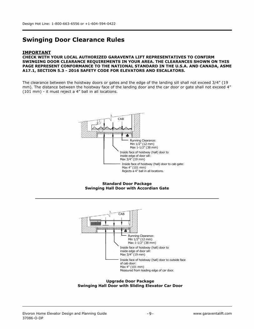
The clearance between the hoistway doors or gates and the edge of the landing sill shall not exceed 3/4” (19 mm). The distance between the hoistway face of the landing door and the car door or gate shall not exceed 4” (101 mm) - it must reject a 4” ball in all locations.
Upgrade Door PackageSwinging Hall Door with Sliding Elevator Car Door
Running Clearance:Min 1/2” (12 mm)Max 1-1/2” (38 mm)
Inside face of hoistway (hall) door to inside edge of door sill:Max 3/4” (19 mm)
Inside face of hoistway (hall) door to outside face of cab door:Max 4” (101 mm)Measured from leading edge of car door.
CAB
Running Clearancemin 1/2” (12 mm)max 1-1/2” (38 mm)
CAB
Standard Door PackageSwinging Hall Door with Accordian Gate
Inside face of hoistway (hall) door to inside edge of door sill:Max 3/4” (19 mm)Inside face of hoistway (hall) door to cab gate:Max 4” (101 mm)Rejects a 4” ball in all locations.
Running Clearance:Min 1/2” (12 mm)Max 1-1/2” (38 mm)
CAB
Accordion Gate with Swing Landing Doors - 1/2" walls
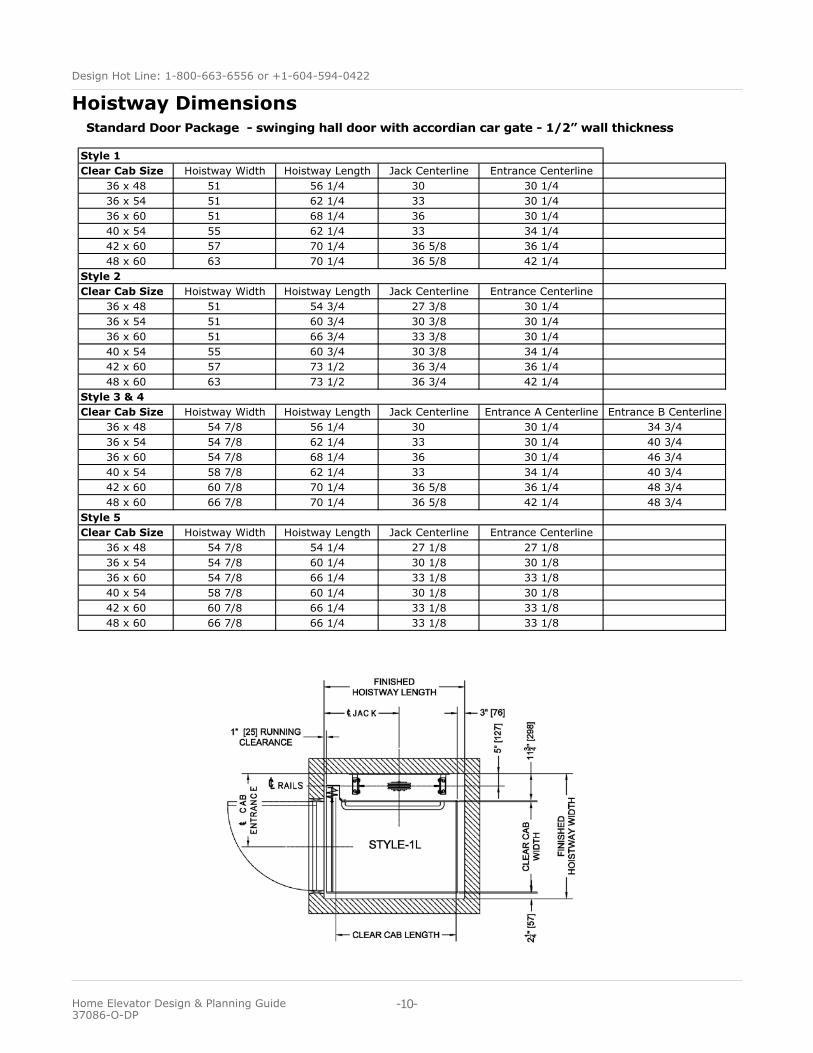
Clear Cab Size Hoistway Width Hoistway Length Jack Centerline Entrance Centerline36 x 48 51 56 1/4 30 30 1/436 x 54 51 62 1/4 33 30 1/436 x 60 51 68 1/4 36 30 1/440 x 54 55 62 1/4 33 34 1/442 x 60 57 70 1/4 36 5/8 36 1/448 x 60 63 70 1/4 36 5/8 42 1/4
Clear Cab Size Hoistway Width Hoistway Length Jack Centerline Entrance Centerline36 x 48 51 54 3/4 27 3/8 30 1/436 x 54 51 60 3/4 30 3/8 30 1/436 x 60 51 66 3/4 33 3/8 30 1/440 x 54 55 60 3/4 30 3/8 34 1/442 x 60 57 73 1/2 36 3/4 36 1/448 x 60 63 73 1/2 36 3/4 42 1/4
Clear Cab Size Hoistway Width Hoistway Length Jack Centerline Entrance A Centerline Entrance B Centerline36 x 48 54 7/8 56 1/4 30 30 1/4 34 3/436 x 54 54 7/8 62 1/4 33 30 1/4 40 3/436 x 60 54 7/8 68 1/4 36 30 1/4 46 3/440 x 54 58 7/8 62 1/4 33 34 1/4 40 3/442 x 60 60 7/8 70 1/4 36 5/8 36 1/4 48 3/448 x 60 66 7/8 70 1/4 36 5/8 42 1/4 48 3/4
Clear Cab Size Hoistway Width Hoistway Length Jack Centerline Entrance Centerline36 x 48 54 7/8 54 1/4 27 1/8 27 1/836 x 54 54 7/8 60 1/4 30 1/8 30 1/836 x 60 54 7/8 66 1/4 33 1/8 33 1/840 x 54 58 7/8 60 1/4 30 1/8 30 1/842 x 60 60 7/8 66 1/4 33 1/8 33 1/848 x 60 66 7/8 66 1/4 33 1/8 33 1/8
Style 1
Style 2
Style 3 & 4
Style 5
-10-
Design Hot Line: 1-800-663-6556 or +1-604-594-0422
Home Elevator Design & Planning Guide 37086-O-DP
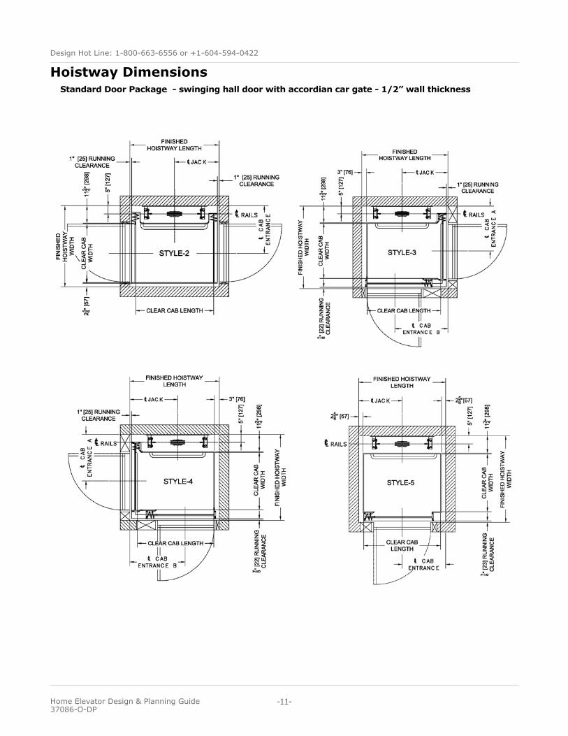
Standard Door Package - swinging hall door with accordian car gate - 1/2” wall thickness
Hoistway Dimensions
-11-
Design Hot Line: 1-800-663-6556 or +1-604-594-0422
Home Elevator Design & Planning Guide 37086-O-DP
Standard Door Package - swinging hall door with accordian car gate - 1/2” wall thickness
Hoistway Dimensions
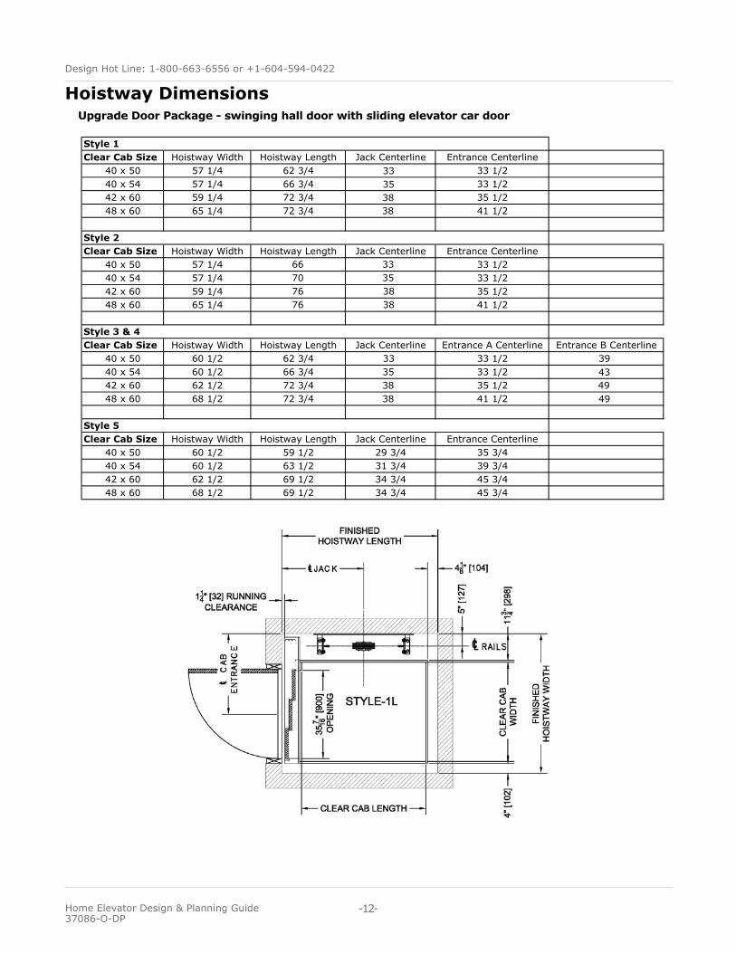
Upgrade Door Package - swinging hall door with sliding elevator car door
Hoistway Dimensions
-12-
Design Hot Line: 1-800-663-6556 or +1-604-594-0422
Home Elevator Design & Planning Guide 37086-O-DP
3 spd Car w/Manual Swing Dr
Clear Cab Size Hoistway Width Hoistway Length Jack Centerline Entrance Centerline40 x 50 57 1/4 62 3/4 33 33 1/240 x 54 57 1/4 66 3/4 35 33 1/242 x 60 59 1/4 72 3/4 38 35 1/248 x 60 65 1/4 72 3/4 38 41 1/2
Clear Cab Size Hoistway Width Hoistway Length Jack Centerline Entrance Centerline40 x 50 57 1/4 66 33 33 1/240 x 54 57 1/4 70 35 33 1/242 x 60 59 1/4 76 38 35 1/248 x 60 65 1/4 76 38 41 1/2
Clear Cab Size Hoistway Width Hoistway Length Jack Centerline Entrance A Centerline Entrance B Centerline40 x 50 60 1/2 62 3/4 33 33 1/2 3940 x 54 60 1/2 66 3/4 35 33 1/2 4342 x 60 62 1/2 72 3/4 38 35 1/2 4948 x 60 68 1/2 72 3/4 38 41 1/2 49
Clear Cab Size Hoistway Width Hoistway Length Jack Centerline Entrance Centerline40 x 50 60 1/2 59 1/2 29 3/4 35 3/440 x 54 60 1/2 63 1/2 31 3/4 39 3/442 x 60 62 1/2 69 1/2 34 3/4 45 3/448 x 60 68 1/2 69 1/2 34 3/4 45 3/4
Style 1
Style 2
Style 3 & 4
Style 5
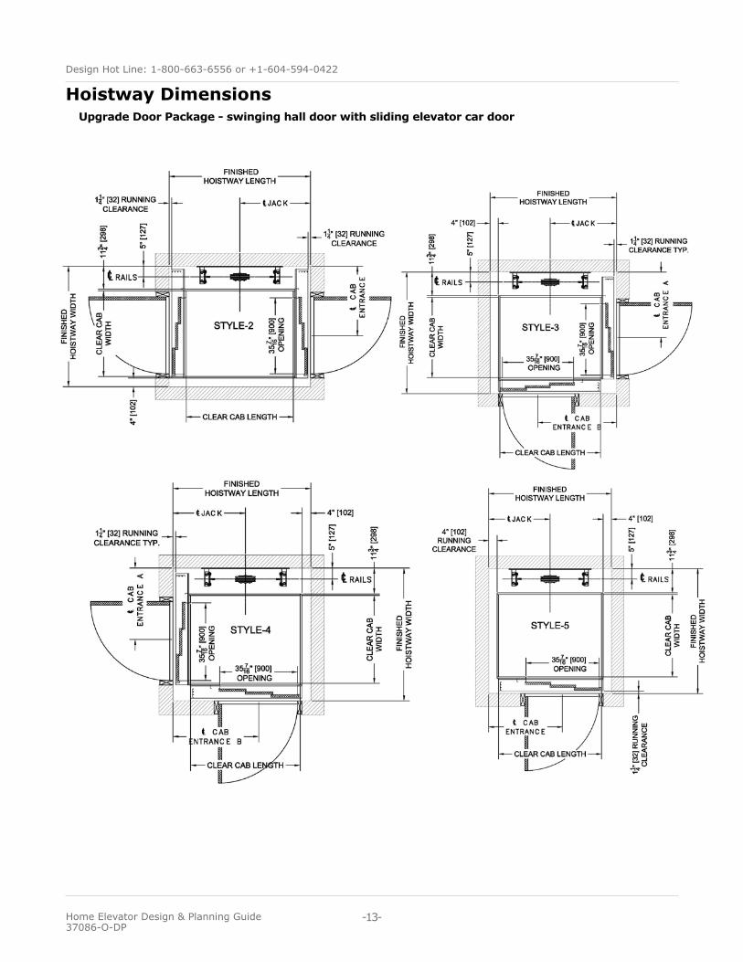
Upgrade Door Package - swinging hall door with sliding elevator car door
Hoistway Dimensions
-13-
Design Hot Line: 1-800-663-6556 or +1-604-594-0422
Home Elevator Design & Planning Guide 37086-O-DP
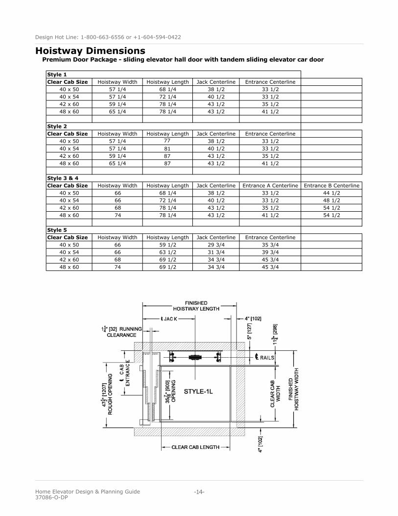
Premium Door Package - sliding elevator hall door with tandem sliding elevator car door3 spd Car w/ 3 spd landing - Std Mount
Clear Cab Size Hoistway Width Hoistway Length Jack Centerline Entrance Centerline40 x 50 57 1/4 68 1/4 38 1/2 33 1/240 x 54 57 1/4 72 1/4 40 1/2 33 1/242 x 60 59 1/4 78 1/4 43 1/2 35 1/248 x 60 65 1/4 78 1/4 43 1/2 41 1/2
Clear Cab Size Hoistway Width Hoistway Length Jack Centerline Entrance Centerline40 x 50 57 1/4 77 38 1/2 33 1/240 x 54 57 1/4 81 40 1/2 33 1/242 x 60 59 1/4 87 43 1/2 35 1/248 x 60 65 1/4 87 43 1/2 41 1/2
Clear Cab Size Hoistway Width Hoistway Length Jack Centerline Entrance A Centerline Entrance B Centerline40 x 50 66 68 1/4 38 1/2 33 1/2 44 1/240 x 54 66 72 1/4 40 1/2 33 1/2 48 1/242 x 60 68 78 1/4 43 1/2 35 1/2 54 1/248 x 60 74 78 1/4 43 1/2 41 1/2 54 1/2
Clear Cab Size Hoistway Width Hoistway Length Jack Centerline Entrance Centerline40 x 50 66 59 1/2 29 3/4 35 3/440 x 54 66 63 1/2 31 3/4 39 3/442 x 60 68 69 1/2 34 3/4 45 3/448 x 60 74 69 1/2 34 3/4 45 3/4
Style 1
Style 2
Style 3 & 4
Style 5
Hoistway Dimensions
-14-
Design Hot Line: 1-800-663-6556 or +1-604-594-0422
Home Elevator Design & Planning Guide 37086-O-DP
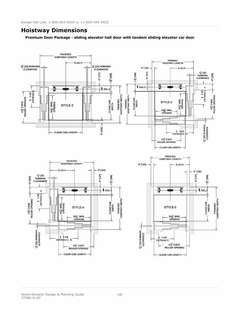
Premium Door Package - sliding elevator hall door with tandem sliding elevator car door
Hoistway Dimensions
-15-
Design Hot Line: 1-800-663-6556 or +1-604-594-0422
Home Elevator Design & Planning Guide 37086-O-DP
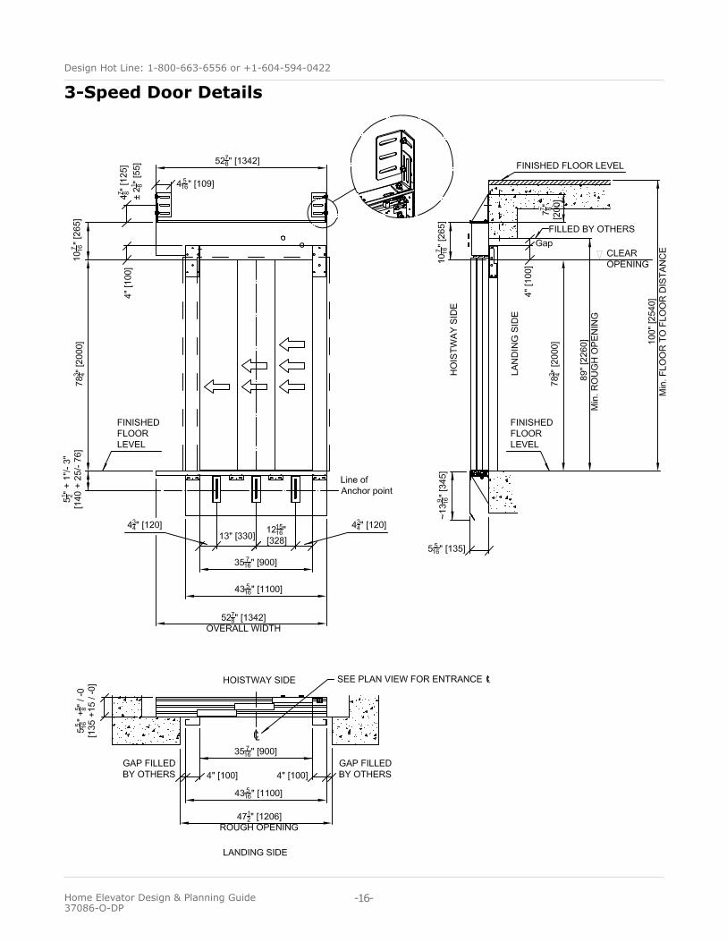
3-Speed Door Details
-16-
Design Hot Line: 1-800-663-6556 or +1-604-594-0422
Home Elevator Design & Planning Guide 37086-O-DP
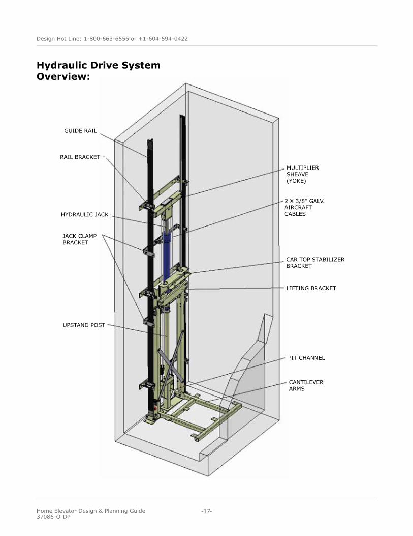
Hydraulic Drive System Overview:
MULTIPLIER SHEAVE(YOKE)
2 X 3/8” GALV. AIRCRAFT CABLES
GUIDE RAIL
RAIL BRACKET
HYDRAULIC JACK
JACK CLAMPBRACKET
UPSTAND POST
CAR TOP STABILIZER BRACKET
LIFTING BRACKET
PIT CHANNEL
CANTILEVER ARMS
-17-
Design Hot Line: 1-800-663-6556 or +1-604-594-0422
Home Elevator Design & Planning Guide 37086-O-DP
Hydraulic Drive System - Technical Reference:General• Capacity - 750 lbs or 1000 lbs optional• 40 ft. per minute (0.2 m/sec) nominal car speed• Up to 6 stops, Maximum 6 landing doors• Maximum floor total travel of 50’• Pit depth of 8” (200 mm) is recommended for units with standard swing doors. 12” (356 mm) pit required for units with automatic sliding car doors.• Overhead clearance of 96” (2440 mm) from upper landing with standard 84” (2135 mm) cab height.• Minimum distance between floors is 10” (255 mm).
Equipment• Two speed control valve with soft start and stop• 1:2 cable hydraulic drive• Single stage Hydraulic drive with two 3/8” diameter aircraft cables• Heavy duty cantilever design utilizing 8 lbs per foot steel elevator guide rail system• Submersible pump and motor assembly for quiet operation• Standard power supply is 230 VAC single phase – 60 Hz. Optional 208 VAC three phase
Controls• Collective automatic operation with illuminated push buttons• PLC (Programmable Logic Controller) with backup system for elevator descent, lights, locks and gate and/or door operator(s) where equipped.• Digital position indicator in cab• Automatic cab lighting• Low oil protection timer circuit• Emergency stop / alarm
Standard Safety Features• Emergency manual lowering
• Slack/broken cable instantaneous safety device• Upper and lower terminal limit switches and a final limit at top and bottom of travel• Hoistway door interlocks ensure the car does not move unless all hall doors and cab gate(s) are closed and locked• Emergency battery backup light and alarm• Certified electrical control system• Automatic bi-directional leveling (Encoder)
Options• Upgrade Door Package (swinging hall door by others with a sliding elevator car door)• Premium Door Package (sliding elevator hall door with tandem sliding elevator car door)• Pipe rupture valve• Keyed hall stations• Recessed telephone box or integrated telephone in cab control panel • Automatic cab gate operator(s)• Automatic hoistway door operator(s)• Custom cab sizes• Buffer Springs – required for hoistways with habitable space under the pit• 96” car height (Standard Door Package Only)
-18-
Design Hot Line: 1-800-663-6556 or +1-604-594-0422
Home Elevator Design & Planning Guide 37086-O-DP
Hydraulic Drive System -Machine Room & Electrical Requirements
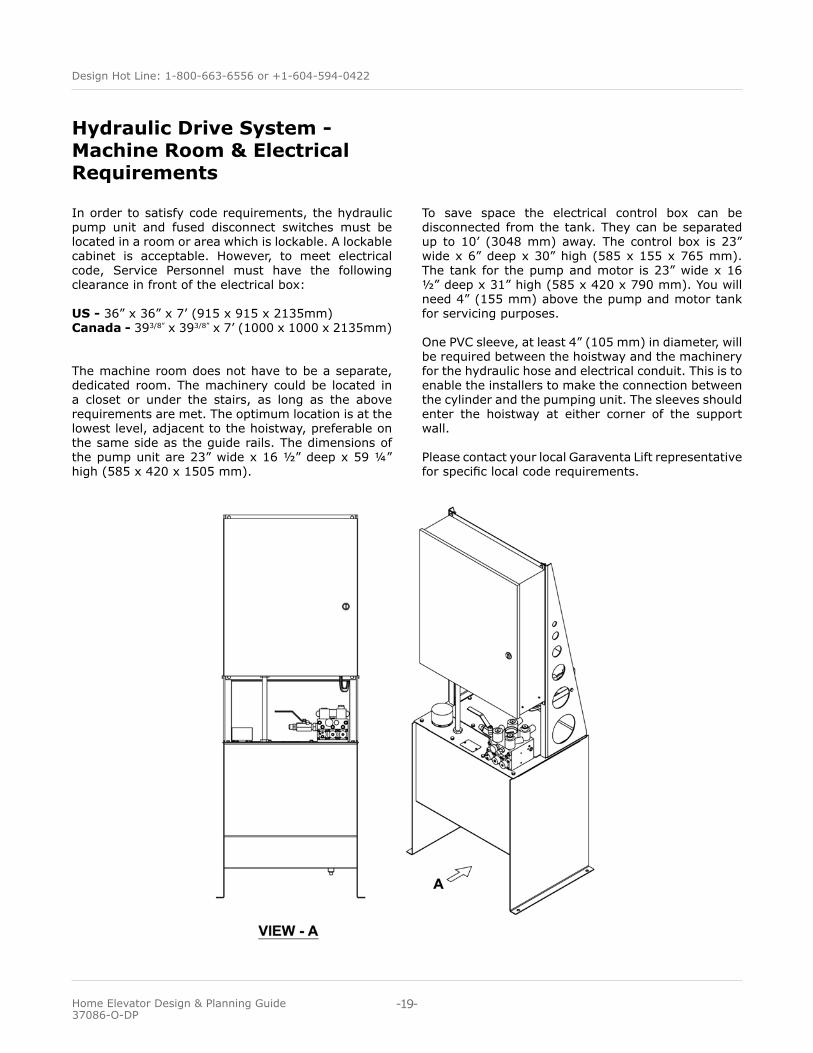
In order to satisfy code requirements, the hydraulic pump unit and fused disconnect switches must be located in a room or area which is lockable. A lockable cabinet is acceptable. However, to meet electrical code, Service Personnel must have the following clearance in front of the electrical box:
US - 36” x 36” x 7’ (915 x 915 x 2135mm)Canada - 393/8” x 393/8” x 7’ (1000 x 1000 x 2135mm)
The machine room does not have to be a separate, dedicated room. The machinery could be located in a closet or under the stairs, as long as the above requirements are met. The optimum location is at the lowest level, adjacent to the hoistway, preferable on the same side as the guide rails. The dimensions of the pump unit are 23” wide x 16 ½” deep x 59 ¼” high (585 x 420 x 1505 mm).
To save space the electrical control box can be disconnected from the tank. They can be separated up to 10’ (3048 mm) away. The control box is 23” wide x 6” deep x 30” high (585 x 155 x 765 mm). The tank for the pump and motor is 23” wide x 16 ½” deep x 31” high (585 x 420 x 790 mm). You will need 4” (155 mm) above the pump and motor tank for servicing purposes.
One PVC sleeve, at least 4” (105 mm) in diameter, will be required between the hoistway and the machinery for the hydraulic hose and electrical conduit. This is to enable the installers to make the connection between the cylinder and the pumping unit. The sleeves should enter the hoistway at either corner of the support wall.
Please contact your local Garaventa Lift representative for specific local code requirements.
-19-
Design Hot Line: 1-800-663-6556 or +1-604-594-0422
Home Elevator Design & Planning Guide 37086-O-DP
LightingYou must provide at least 100 lx lighting over the pumping unit and disconnect switches.
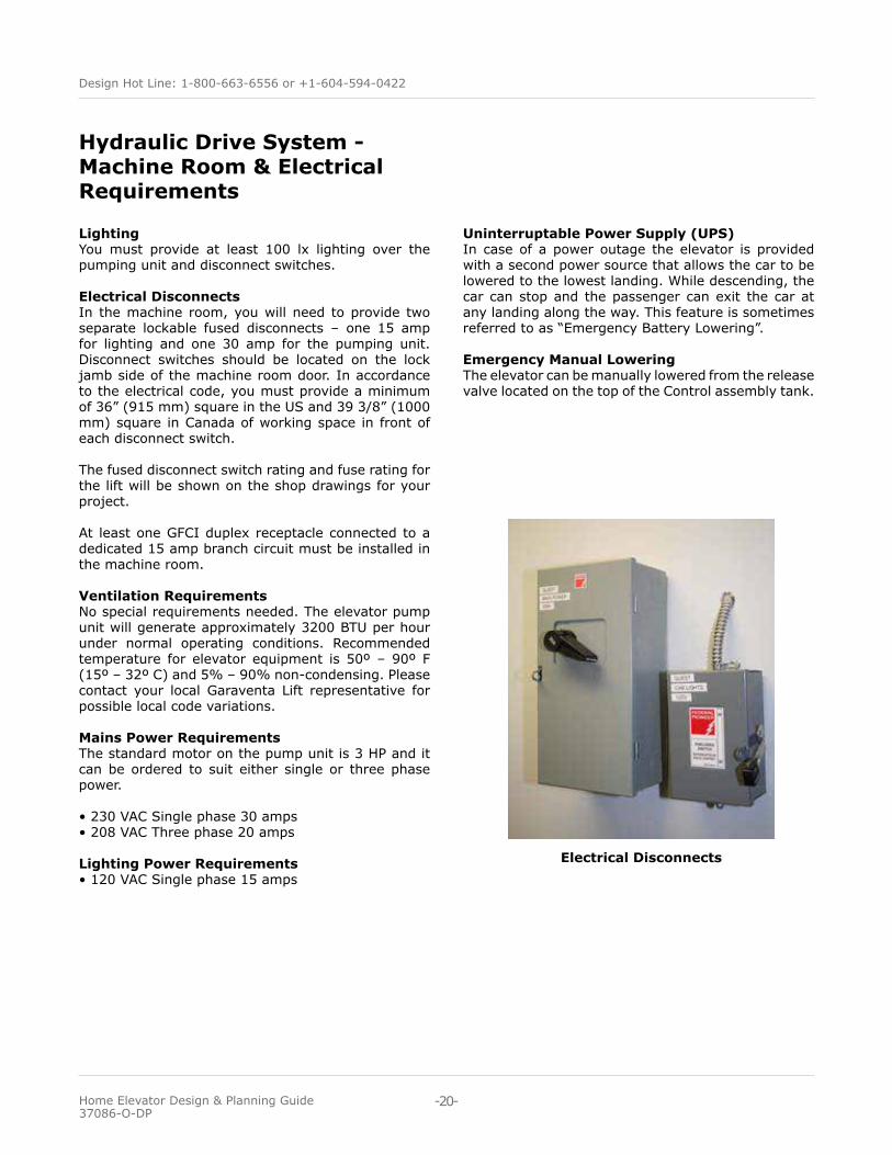
Electrical Disconnects In the machine room, you will need to provide two separate lockable fused disconnects – one 15 amp for lighting and one 30 amp for the pumping unit. Disconnect switches should be located on the lock jamb side of the machine room door. In accordance to the electrical code, you must provide a minimum of 36” (915 mm) square in the US and 39 3/8” (1000 mm) square in Canada of working space in front of each disconnect switch.
The fused disconnect switch rating and fuse rating for the lift will be shown on the shop drawings for your project.
At least one GFCI duplex receptacle connected to a dedicated 15 amp branch circuit must be installed in the machine room.
Ventilation RequirementsNo special requirements needed. The elevator pump unit will generate approximately 3200 BTU per hour under normal operating conditions. Recommended temperature for elevator equipment is 50º – 90º F (15º – 32º C) and 5% – 90% non-condensing. Please contact your local Garaventa Lift representative for possible local code variations.
Mains Power RequirementsThe standard motor on the pump unit is 3 HP and it can be ordered to suit either single or three phase power.
• 230 VAC Single phase 30 amps• 208 VAC Three phase 20 amps
Lighting Power Requirements• 120 VAC Single phase 15 amps
Uninterruptable Power Supply (UPS)In case of a power outage the elevator is provided with a second power source that allows the car to be lowered to the lowest landing. While descending, the car can stop and the passenger can exit the car at any landing along the way. This feature is sometimes referred to as “Emergency Battery Lowering”.
Emergency Manual LoweringThe elevator can be manually lowered from the release valve located on the top of the Control assembly tank.
Electrical Disconnects
Hydraulic Drive System -Machine Room & Electrical Requirements
-20-
Design Hot Line: 1-800-663-6556 or +1-604-594-0422
Home Elevator Design & Planning Guide 37086-O-DP
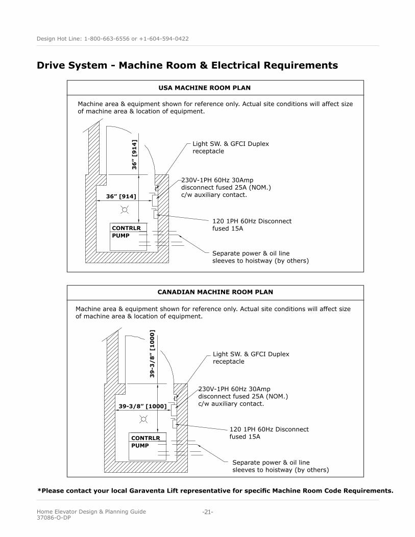
*Please contact your local Garaventa Lift representative for specific Machine Room Code Requirements.
Drive System - Machine Room & Electrical Requirements
Machine area & equipment shown for reference only. Actual site conditions will affect size of machine area & location of equipment.
Light SW. & GFCI Duplex receptacle
230V-1PH 60Hz 30Amp disconnect fused 25A (NOM.) c/w auxiliary contact.
120 1PH 60Hz Disconnect fused 15A
Separate power & oil line sleeves to hoistway (by others)
USA MACHINE ROOM PLAN
36” [914]
36
” [9
14
]
CONTRLRPUMP
Machine area & equipment shown for reference only. Actual site conditions will affect size of machine area & location of equipment.
CANADIAN MACHINE ROOM PLAN
Light SW. & GFCI Duplex receptacle
230V-1PH 60Hz 30Amp disconnect fused 25A (NOM.) c/w auxiliary contact.
120 1PH 60Hz Disconnect fused 15A
Separate power & oil line sleeves to hoistway (by others)
CONTRLRPUMP
39-3/8” [1000]
39
-3/
8”
[10
00
]
-21-
Design Hot Line: 1-800-663-6556 or +1-604-594-0422
Home Elevator Design & Planning Guide 37086-O-DP
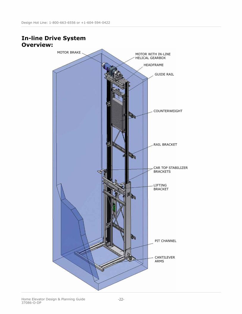
In-line Drive System Overview:
MOTOR BRAKE MOTOR WITH IN-LINE HELICAL GEARBOX
HEADFRAME
GUIDE RAIL
COUNTERWEIGHT
RAIL BRACKET
CAR TOP STABILIZER BRACKETS
LIFTING BRACKET
PIT CHANNEL
CANTILEVER ARMS
-22-
Design Hot Line: 1-800-663-6556 or +1-604-594-0422
Home Elevator Design & Planning Guide 37086-O-DP
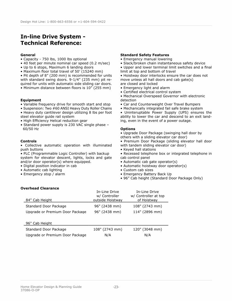
General• Capacity - 750 lbs, 1000 lbs optional• 40 feet per minute nominal car speed (0.2 m/sec) • Up to 6 stops, Maximum 6 landing doors• Maximum floor total travel of 50’ (15240 mm)• Pit depth of 8” (200 mm) is recommended for units with standard swing doors. 9-1/4” (235 mm) pit re-quired for units with automatic side sliding car doors. • Minimum distance between floors is 10” (255 mm)
Equipment• Variable frequency drive for smooth start and stop• Suspension: Two #60 ANSI Heavy Duty Roller Chains• Heavy duty cantilever design utilizing 8 lbs per foot steel elevator guide rail system• High Efficiency Helical reduction gear• Standard power supply is 230 VAC single phase – 60/50 Hz
Controls• Collective automatic operation with illuminated push buttons• PLC (Programmable Logic Controller) with backup system for elevator descent, lights, locks and gate and/or door operator(s) where equipped.• Digital position indicator in cab• Automatic cab lighting• Emergency stop / alarm
In-line Drive System - Technical Reference:
Standard Safety Features• Emergency manual lowering• Slack/broken chain instantaneous safety device• Upper and lower terminal limit switches and a final limit at top and bottom of travel• Hoistway door interlocks ensure the car does not move unless all hall doors and cab gate(s) are closed and locked• Emergency light and alarm• Certified electrical control system• Mechanical Overspeed Governor with electronic detection• Car and Counterweight Over Travel Bumpers• Mechanically integrated fail safe brake system• Uninteruptable Power Supply (UPS) ensures the ability to lower the car and descend to an exit land-ing, even in the event of a power outage.
Options• Upgrade Door Package (swinging hall door by others with a sliding elevator car door)• Premium Door Package (sliding elevator hall door with tandem sliding elevator car door)• Keyed hall stations• Recessed telephone box or integrated telephone in cab control panel • Automatic cab gate operator(s)• Automatic hoistway door operator(s)• Custom cab sizes• Emergency Battery Back Up• 96” Cab height (Standard Door Package Only)
84" Cab Height
In-Line Drivew/ Controller
outside Hoistway
In-Line Drivew/ Controller at top
of Hoistway
Standard Door Package 96" (2438 mm) 108" (2743 mm)Upgrade or Premium Door Package 96" (2438 mm) 114" (2896 mm)
96" Cab Height
Standard Door Package 108" (2743 mm) 120" (3048 mm)Upgrade or Premium Door Package N/A N/A
Overhead Clearance
-23-
Design Hot Line: 1-800-663-6556 or +1-604-594-0422
Home Elevator Design & Planning Guide 37086-O-DP
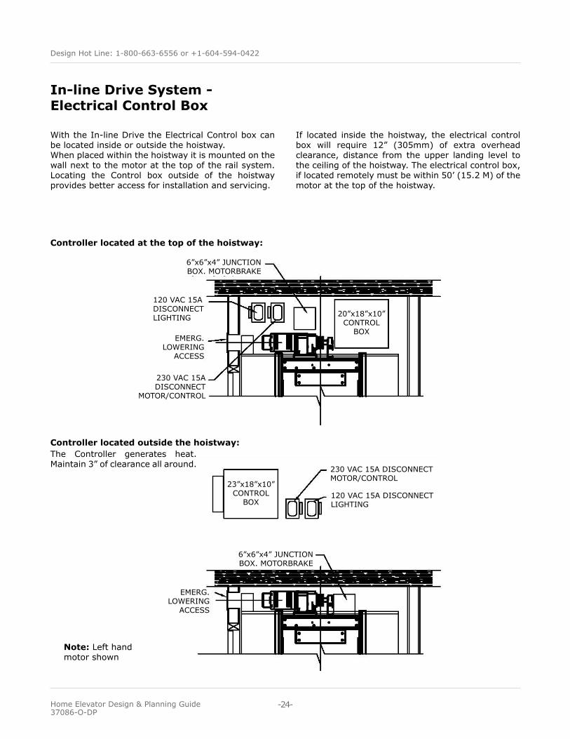
In-line Drive System - Electrical Control Box
With the In-line Drive the Electrical Control box can be located inside or outside the hoistway. When placed within the hoistway it is mounted on the wall next to the motor at the top of the rail system. Locating the Control box outside of the hoistway provides better access for installation and servicing.
Controller located at the top of the hoistway:
Controller located outside the hoistway:
Note: Left hand motor shown
If located inside the hoistway, the electrical control box will require 12” (305mm) of extra overhead clearance, distance from the upper landing level to the ceiling of the hoistway. The electrical control box, if located remotely must be within 50’ (15.2 M) of the motor at the top of the hoistway.
23”x18”x10”CONTROL
BOX
20”x18”x10”CONTROL
BOX
230 VAC 15A DISCONNECT MOTOR/CONTROL
230 VAC 15A DISCONNECT
MOTOR/CONTROL
120 VAC 15A DISCONNECT LIGHTING
120 VAC 15A DISCONNECT LIGHTING
EMERG.LOWERING
ACCESS
EMERG.LOWERING
ACCESS
6”x6”x4” JUNCTIONBOX. MOTORBRAKE
6”x6”x4” JUNCTIONBOX. MOTORBRAKE
The Controller generates heat. Maintain 3” of clearance all around.
-24-
Design Hot Line: 1-800-663-6556 or +1-604-594-0422
Home Elevator Design & Planning Guide 37086-O-DP
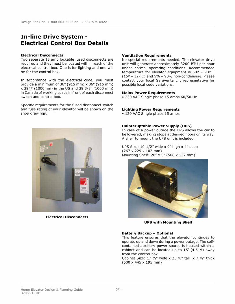
Electrical Disconnects Two separate 15 amp lockable fused disconnects are required and they must be located within reach of the electrical control box. One is for lighting and one will be for the control box.
In accordance with the electrical code, you must provide a minimum of 36” (915 mm) x 36” (915 mm) x 393/8” (1000mm) in the US and 39 3/8” (1000 mm) in Canada of working space in front of each disconnect switch and control box.
Specific requirements for the fused disconnect switch and fuse rating of your elevator will be shown on the shop drawings.
In-line Drive System - Electrical Control Box Details
Ventilation RequirementsNo special requirements needed. The elevator drive unit will generate approximately 3200 BTU per hour under normal operating conditions. Recommended temperature for elevator equipment is 50º – 90º F (15º – 32º C) and 5% – 90% non-condensing. Please contact your local Garaventa Lift representative for possible local code variations.
Mains Power Requirements• 230 VAC Single phase 15 amps 60/50 Hz
Lighting Power Requirements• 120 VAC Single phase 15 amps
Uninteruptable Power Supply (UPS)In case of a power outage the UPS allows the car to be lowered, making stops at desired floors on its way. A shelf to mount the UPS unit is included.
UPS Size: 10-1/2” wide x 9” high x 4” deep(267 x 229 x 102 mm)Mounting Shelf: 20” x 5” (508 x 127 mm)
Electrical DisconnectsUPS with Mounting Shelf
Battery Backup – OptionalThis feature ensures that the elevator continues to operate up and down during a power outage. The self-contained auxiliary power source is housed within a cabinet and can be located up to 15’ (4.5 M) away from the control box. Cabinet Size: 17 ½” wide x 23 ½” tall x 7 ⅝” thick (600 x 445 x 195 mm)
-25-
Design Hot Line: 1-800-663-6556 or +1-604-594-0422
Home Elevator Design & Planning Guide 37086-O-DP
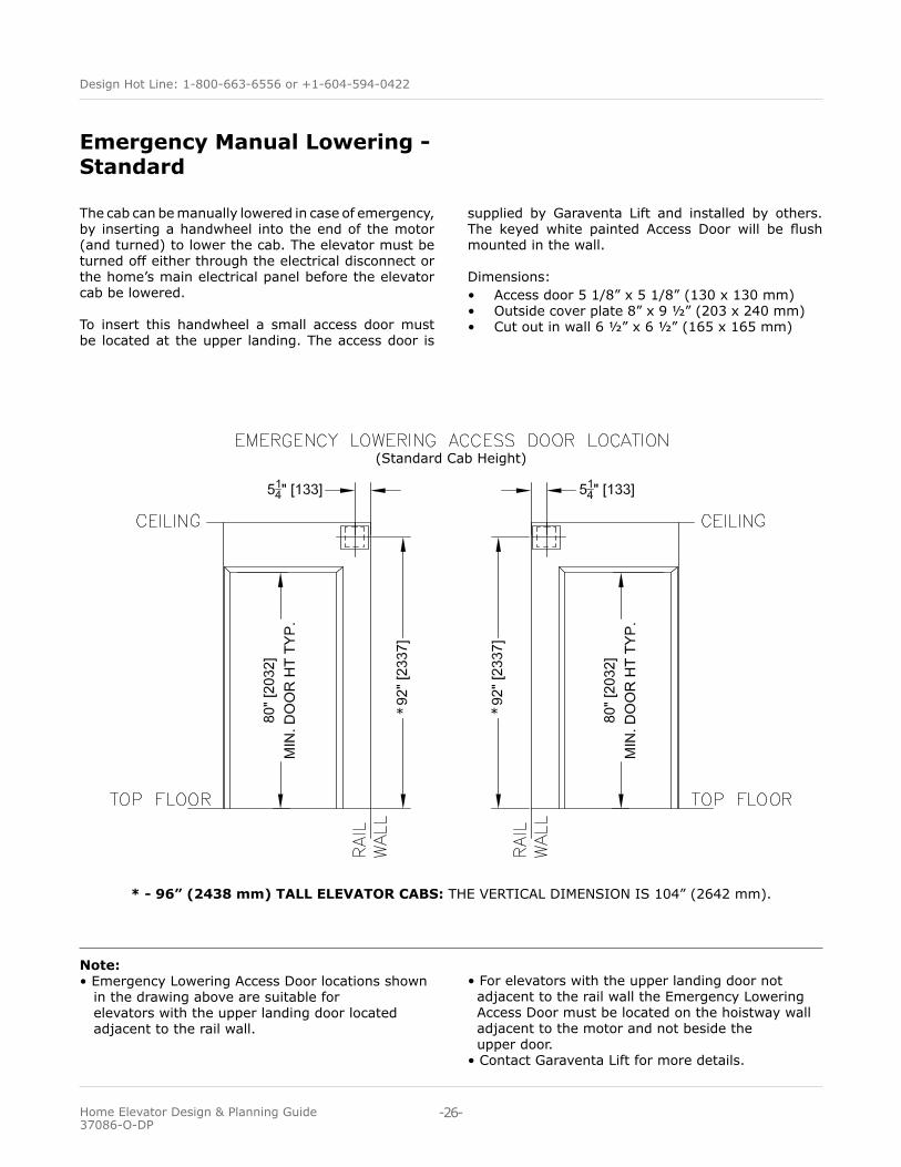
Emergency Manual Lowering - Standard
Note: • Emergency Lowering Access Door locations shown in the drawing above are suitable for elevators with the upper landing door located adjacent to the rail wall.
• For elevators with the upper landing door not adjacent to the rail wall the Emergency Lowering Access Door must be located on the hoistway wall adjacent to the motor and not beside the upper door. • Contact Garaventa Lift for more details.
The cab can be manually lowered in case of emergency, by inserting a handwheel into the end of the motor (and turned) to lower the cab. The elevator must be turned off either through the electrical disconnect or the home’s main electrical panel before the elevator cab be lowered.
To insert this handwheel a small access door must be located at the upper landing. The access door is
supplied by Garaventa Lift and installed by others. The keyed white painted Access Door will be flush mounted in the wall.
Dimensions: • Access door 5 1/8” x 5 1/8” (130 x 130 mm)• Outside cover plate 8” x 9 ½” (203 x 240 mm)• Cut out in wall 6 ½” x 6 ½” (165 x 165 mm)
* - 96” (2438 mm) TALL ELEVATOR CABS: THE VERTICAL DIMENSION IS 104” (2642 mm).
(Standard Cab Height)
**
-26-
Design Hot Line: 1-800-663-6556 or +1-604-594-0422
Home Elevator Design & Planning Guide 37086-O-DP
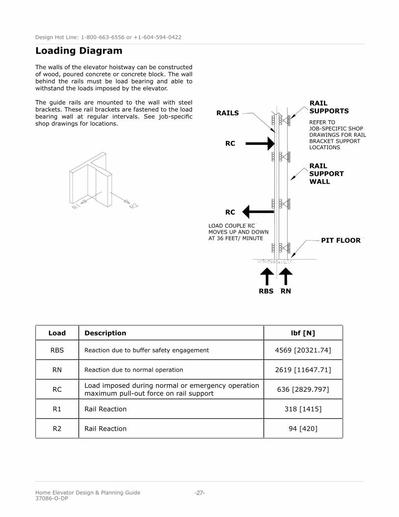
The walls of the elevator hoistway can be constructed of wood, poured concrete or concrete block. The wall behind the rails must be load bearing and able to withstand the loads imposed by the elevator. The guide rails are mounted to the wall with steel brackets. These rail brackets are fastened to the load bearing wall at regular intervals. See job-specific shop drawings for locations.
Loading Diagram
Load Description lbf [N]
RBS Reaction due to buffer safety engagement 4569 [20321.74]
RN Reaction due to normal operation 2619 [11647.71]
RC Load imposed during normal or emergency operation maximum pull-out force on rail support 636 [2829.797]
R1 Rail Reaction 318 [1415]
R2 Rail Reaction 94 [420]
LOAD COUPLE RC MOVES UP AND DOWN AT 36 FEET/ MINUTE
RBS
RAILSRAIL SUPPORTS
RAIL SUPPORTWALL
PIT FLOOR
RN
RC
RC
REFER TO JOB-SPECIFIC SHOP DRAWINGS FOR RAIL BRACKET SUPPORT LOCATIONS
-27-
Design Hot Line: 1-800-663-6556 or +1-604-594-0422
Home Elevator Design & Planning Guide 37086-O-DP

Authorized Garaventa Lift Representative www.garaventalift.com
Creating An Accessible World
© Garaventa Li f t . As we are continuously improving our products, specifications outlined in this brochure are subject to change without notice.
Printed in Canada37086-O-DP