Embed Size (px)
Citation preview
ArtiraDesign and Planning Guide

Please note:
Dimensions provided in this Guide are for REFERENCE ONLY and should not be used for site preparation or construction.
Table of Contents
What is an Inclined Platform Lift? ............................................................................................................................... 4
Why an Inclined Platform Lift? ..................................................................................................................................... 4
Design Versatility ............................................................................................................................................................ 4
Finishes ............................................................................................................................................................................. 6
Where You’ll Find Our Lifts ........................................................................................................................................... 6
How it Works .................................................................................................................................................................... 7
Component Identification ............................................................................................................................................. 8
Platform ............................................................................................................................................................................ 9
Standard Platform Safety Features ........................................................................................................... 10
Optional Platform Features ........................................................................................................................ 11
Call Stations .................................................................................................................................................................... 12
Lower Landing Configuration Options ...................................................................................................................... 13
Required Turning Clearances ....................................................................................................................................... 16
Standard Upper Landing Drive Configurations ........................................................................................................ 17
Alternate Drive Configurations ................................................................................................................................... 19
Drive System ................................................................................................................................................................... 20
Additional Component Options .................................................................................................................................. 21
Guide Tubes .................................................................................................................................................................... 22
Platform Storage at Upper Landing (Optional) ....................................................................................................... 23
Platform Running Clearances Required for Platform Folded Up ........................................................................ 24
Minimum Overhead Clearances to Meet Code Requirements ............................................................................. 24
Attachment Methods .................................................................................................................................................... 26
Wall Height Requirements for Direct Mounting ..................................................................................................... 28
Loading Diagram ............................................................................................................................................................ 29
Technical Reference of Standard Features ............................................................................................................... 30
Typical Wiring Layout ..................................................................................................................................................... 31
What is an Inclined Platform Lift?
An inclined platform lift easily transports a passenger in a wheelchair, or someone who has difficulty using stairs. The lift can be operated independently or by an attendant with a attendant remote control (optional item). Compatible for indoor and outdoor applications, the Garaventa Artira Inclined Platform Lift is a versatile, attractive and cost-effective accessibility solution.
Why a GSL Artira?
• Meets ADA Requirements - Garaventa inclined platform lifts are approved as a means to provide public building access. Compliant to ASME A18.1 (USA) and CSA B355 (Canada).
• The Established Benchmark - Garaventa Lift has been designing and manufacturing inclined platform lifts since 1978. More Garaventa inclined platform lifts are installed in commercial buildings in North America than all other current manufacturers combined.
• Minimal or No Stairway Modification - The Artira will fit into most existing stairways and do not require specially constructed hoistways.
• Space Saver - The Artira doea not permanently occupy valuable floor space and, when folded, is the most compact inclined lift available. It is also capable of turning tighter corners than any other lift on the market.
• Safety - The Artira is available with a large selection of safety and useability options. It is considered to be one of the most user-friendly inclined platform lift available today.
Design Assistance
With over 35 years of experience, Garaventa Lift is willing and able to overcome almost any design challenge you face. Please call our Design Hot Line with your accessibility challenge.
1-800-663-6556 or 1+604-594-0422
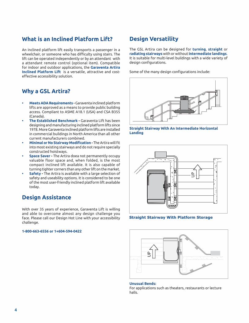
Design Versatility
The GSL Artira can be designed for turning, straight or radiating stairways with or without intermediate landings. It is suitable for multi-level buildings with a wide variety of design configurations.
Some of the many design configurations include:
Straight Stairway With An Intermediate Horizontal Landing
Straight Stairway With Platform Storage
UP
Unusual Bends:For applications such as theaters, restaurants or lecture halls.
UP
4
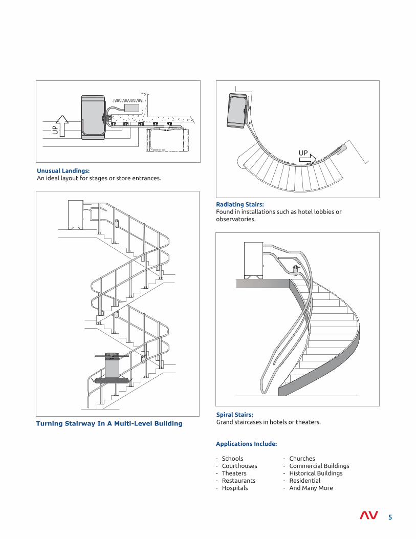
Unusual Landings: An ideal layout for stages or store entrances.
UP
Turning Stairway In A Multi-Level Building
Applications Include:
- Schools - Churches- Courthouses - Commercial Buildings- Theaters - Historical Buildings- Restaurants - Residential- Hospitals - And Many More
Spiral Stairs:Grand staircases in hotels or theaters.
Radiating Stairs:Found in installations such as hotel lobbies or observatories.
UP
5
The GSL Artira is finished in a durable polyester powder paint coating that is electrostatically applied and baked at 210° C (410° F).
Standard Color
Garaventa Lift’s standard color, Satin Grey (fine textured), complements a variety of modern and traditional decors (color samples are available upon request).
Custom Colors (Optional)
Garaventa Lift offers a choice of colors from the internation-ally accepted RAL color charts (color samples are available upon request).
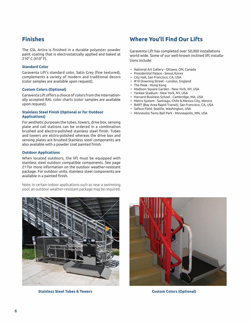
Stainless Steel Finish (Optional or for Outdoor Applications)
For aesthetic purposes the tubes, towers, drive box, sensing plate and call stations can be ordered in a combination brushed and electro-polished stainless steel finish. Tubes and towers are elctro-polished whereas the drive box and sensing plates are brushed.Stainless steel components are also available with a powder coat painted finish.
Outdoor Applications
When located outdoors, the lift must be equipped with stainless steel outdoor compatible components. See page 21 for more information on the outdoor weather-resistant package. For outdoor units, stainless steel components are available in a painted finish.
Note: In certain indoor applications such as near a swimming pool, an outdoor weather-resistant package may be required.
Finishes
Stainless Steel Tubes & Towers Custom Colors (Optional)
6
Where You’ll Find Our Lifts
Garaventa Lift has completed over 50,000 installations world wide. Some of our well-known inclined lift installa-tions include: • National Art Gallery - Ottawa, ON, Canada • Presidential Palace - Seoul, Korea • City Hall, San Francisco, CA, USA • #10 Downing Street - London, England • The Peak - Hong Kong • Madison Square Garden - New York, NY, USA • Yankee Stadium - New York, NY, USA • Harvard Business School - Cambridge, MA, USA • Metro System - Santiago, Chile & Mexico City, Mexico • BART (Bay Area Rapid Transit), San Francisco, CA, USA • Safeco Field, Seattle, Washington, USA • Minnesota Twins Ball Park - Minneapolis, MN, USA
How it Works
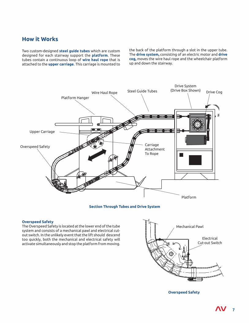
Two custom-designed steel guide tubes which are custom designed for each stairway support the platform. These tubes contain a continuous loop of wire haul rope that is attached to the upper carriage. This carriage is mounted to
Overspeed Safety
Overspeed SafetyThe Overspeed Safety is located at the lower end of the tube system and consists of a mechanical pawl and electrical cut-out switch. In the unlikely event that the lift should descend too quickly, both the mechanical and electrical safety will activate simultaneously and stop the platform from moving.
Electrical Cut-out Switch
Mechanical Pawl
Section Through Tubes and Drive System
Drive System(Drive Box Shown)
Wire Haul Rope
Carriage Attachment To Rope
Upper Carriage
Steel Guide Tubes
Platform Hanger
Drive Cog
Overspeed Safety
Platform
the back of the platform through a slot in the upper tube. The drive system, consisting of an electric motor and drive cog, moves the wire haul rope and the wheelchair platform up and down the stairway.
7
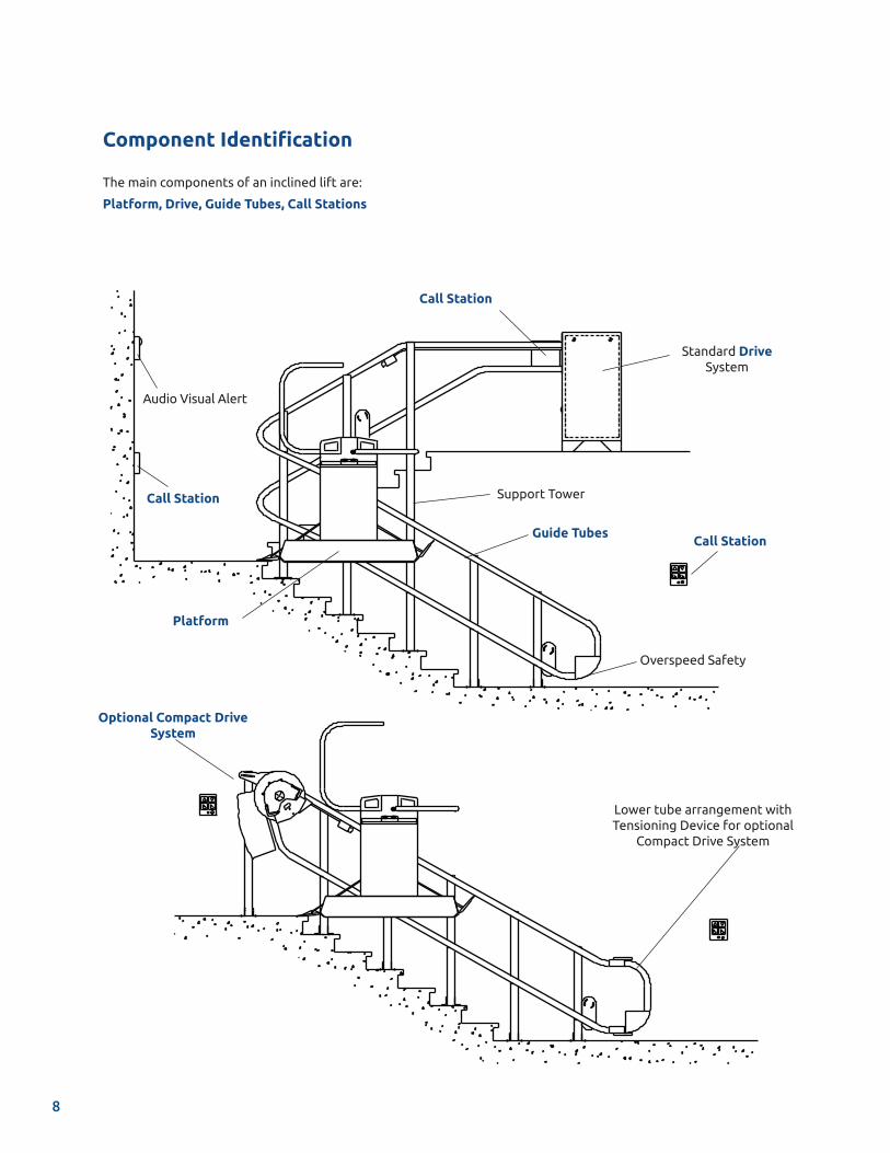
Component Identification
Platform, Drive, Guide Tubes, Call Stations
The main components of an inclined lift are:
Call Station
Audio Visual Alert
Support TowerCall Station
Platform
Guide Tubes
Overspeed Safety
Standard Drive System
Call Station
Optional Compact Drive System
Lower tube arrangement with Tensioning Device for optional
Compact Drive System
8
Optional Attendant Remote Control Unit
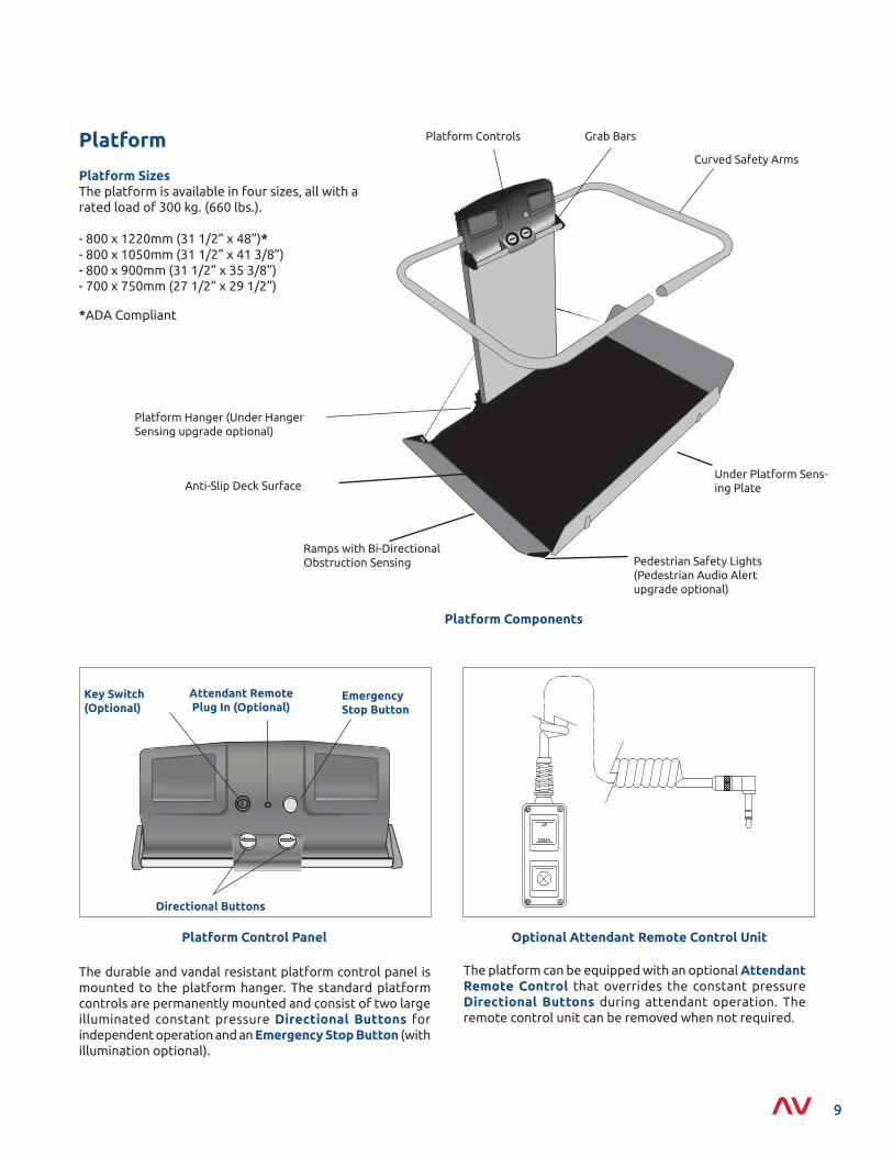
The platform can be equipped with an optional Attendant Remote Control that overrides the constant pressure Directional Buttons during attendant operation. The remote control unit can be removed when not required.
Platform
Platform SizesThe platform is available in four sizes, all with a rated load of 300 kg. (660 lbs.).
- 800 x 1220mm (31 1/2” x 48”)*- 800 x 1050mm (31 1/2” x 41 3/8”)- 800 x 900mm (31 1/2” x 35 3/8”)- 700 x 750mm (27 1/2” x 29 1/2”)
*ADA Compliant
Platform Components
Platform Control Panel
The durable and vandal resistant platform control panel is mounted to the platform hanger. The standard platform controls are permanently mounted and consist of two large illuminated constant pressure Directional Buttons for independent operation and an Emergency Stop Button (with illumination optional).
EmergencyStop Button
Directional Buttons
Attendant Remote Plug In (Optional)
Key Switch(Optional)
Anti-Slip Deck Surface
Curved Safety Arms
Platform Controls
Ramps with Bi-Directional Obstruction Sensing Pedestrian Safety Lights
(Pedestrian Audio Alert upgrade optional)
Grab Bars
Platform Hanger (Under Hanger Sensing upgrade optional)
Under Platform Sens-ing Plate
9
Standard Platform Safety Features
Safety SensingThe platform is equipped with safety sensors listed below. These sensors will automatically stop the lift when activated by 1.8 kg (4 lbs.) of pressure. The platform can then be backed away from the obstruction.
• Leading Ramp Sensor When the platform is called to or from the landing area in the folded up position the leading ramp is sensitive to obstructions.
• Bi-Directional Ramp Sensing The inside and outside surfaces of the leading ramp are obstruction sensitive in the direction of travel.
• Under Platform Sensing Plate The under platform sensing plate detects obstacles underneath the platform.
Curved Safety ArmsFully automatic 32mm (1 1/4”) diameter Curved Safety Arms further increase the safety of the GSL Artira. They are directly over the perimeter of the platform, guarding the user. The top of the arm is located 948mm (37 3/8”) above the plat-form deck. If arms should encounter an obstruction, they will retract to the up position upon release of the directional control button.
Emergency Stop ButtonLocated on the platform control panel, this large red but-ton is used to stop the lift in an emergency.
Smooth Start & StopThe Artira is equipped with a variable speed drive, pro-grammed to automatically slow down while travelling through certain sections of the staircase. The platform is programmed to slow to 50% of the normal travel speed well in advance of corners and resumes full speed when the platform reaches straight sections. The lift controller is also programmed to slow the platform travel speed when ap-proaching and departing landings.
Grab BarThe Grab Bar is a 25mm (1”) diameter aluminum bar located on the front face of the platform control panel to assist pas-sengers in loading and unloading.
Pedestrian Safety Lights This illuminated tube lighting located at the base of the ramps visually alerts pedestrians of the platform’s location during travel, while still being discreet to the passenger.
Emergency FoldIn an emergency the platform can be manually folded and will lock in the folded position.
10
Optional Platform Features
Platform LockThis lock secures the platform in its folded position protecting the unit from vandalism.
Under Hanger Obstruction SensingWhen the platform moves to or from the landing area in the folded up position, sensors on the underside of the hanger will automatically stop the lift when activated by a minimum of 1.8 kg (4 lbs.) of pressure.
Pedestrian Audio AlertWhen the platform is folded up and traveling between stations, an audio chime on the platform is activated indicating the lift is in motion. The chime is deactivated when a passenger is using the lift.
Folding Seat Designed for use by ambulatory passengers, this folding seat is equipped with a safety belt. For commercial applications, the folding seat and seat belt are required by the ASME A18.1 safety code in the USA.
Dek-Lite (requires folding seat)Mounted below the folding seat, this light provides additional lighting to the platform.
Side LoadFor confined lower landing spaces, an automatically deployed side load ramp allows the passenger to wheel onto the platform diagonally, offering easier access.
Auto FoldThis feature automatically folds the platform if it is left unfolded at a landing for a period of time.
Platform on Board AlarmWhen the Emergency Stop Button is activated it illuminates and an alarm located on the platform. The alarm will alert others that the passenger on the lift requires assistance.
Attendant Remote ControlThe Attendant Remote Control overrides the platform controls allowing an attendant to operate the lift.
Key SwitchTo meet some local code requirements a key switch can be added to the platform control panel.
Side of Hanger Optical SensingMounted on the side of the platform hanger, these sensors are designed to protect pedestrian traffic. This feature detects possible obstructions in open-core stairways and while the lift turns corners.
Note: In some jurisdictions certain optional features are either not permitted or mandatory depending on local codes. Please consult your local Garaventa representative for clarification.
11
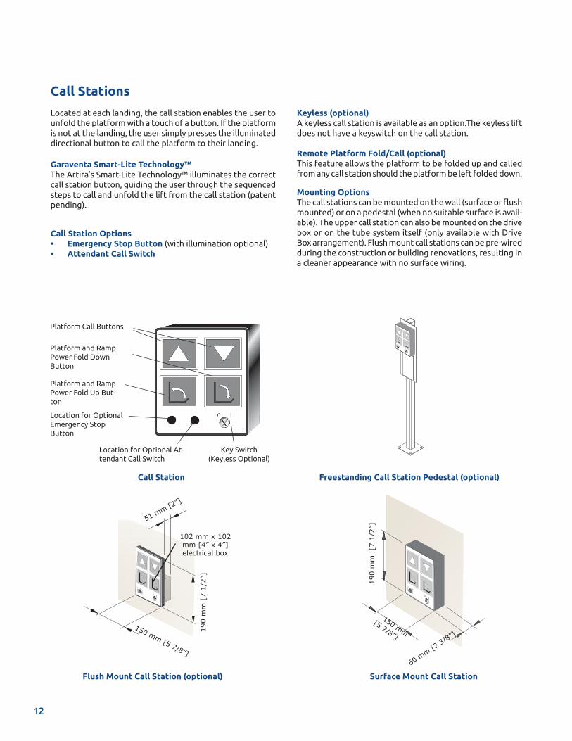
Call Station
Platform Call Buttons
Platform and Ramp Power Fold Down Button
Key Switch(Keyless Optional)
Platform and Ramp Power Fold Up But-ton
Location for Optional At-tendant Call Switch
Location for Optional Emergency Stop Button
Call Stations
Located at each landing, the call station enables the user to unfold the platform with a touch of a button. If the platform is not at the landing, the user simply presses the illuminated directional button to call the platform to their landing.
Garaventa Smart-Lite Technology™The Artira’s Smart-Lite Technology™ illuminates the correct call station button, guiding the user through the sequenced steps to call and unfold the lift from the call station (patent pending).
Call Station Options• Emergency Stop Button (with illumination optional) • Attendant Call Switch
Freestanding Call Station Pedestal (optional)
Keyless (optional)A keyless call station is available as an option.The keyless lift does not have a keyswitch on the call station.
Remote Platform Fold/Call (optional)This feature allows the platform to be folded up and called from any call station should the platform be left folded down.
Mounting OptionsThe call stations can be mounted on the wall (surface or flush mounted) or on a pedestal (when no suitable surface is avail-able). The upper call station can also be mounted on the drive box or on the tube system itself (only available with Drive Box arrangement). Flush mount call stations can be pre-wired during the construction or building renovations, resulting in a cleaner appearance with no surface wiring.
Surface Mount Call Station
190
mm
[7
1/2
”]
150 mm
[5 7/8”]
60 m
m [2 3/
8”]
Flush Mount Call Station (optional)
190
mm
[7
1/2”
]
150 mm [5 7/8”]
51 mm [2”]
102 mm x 102 mm [4” x 4”] electrical box
12
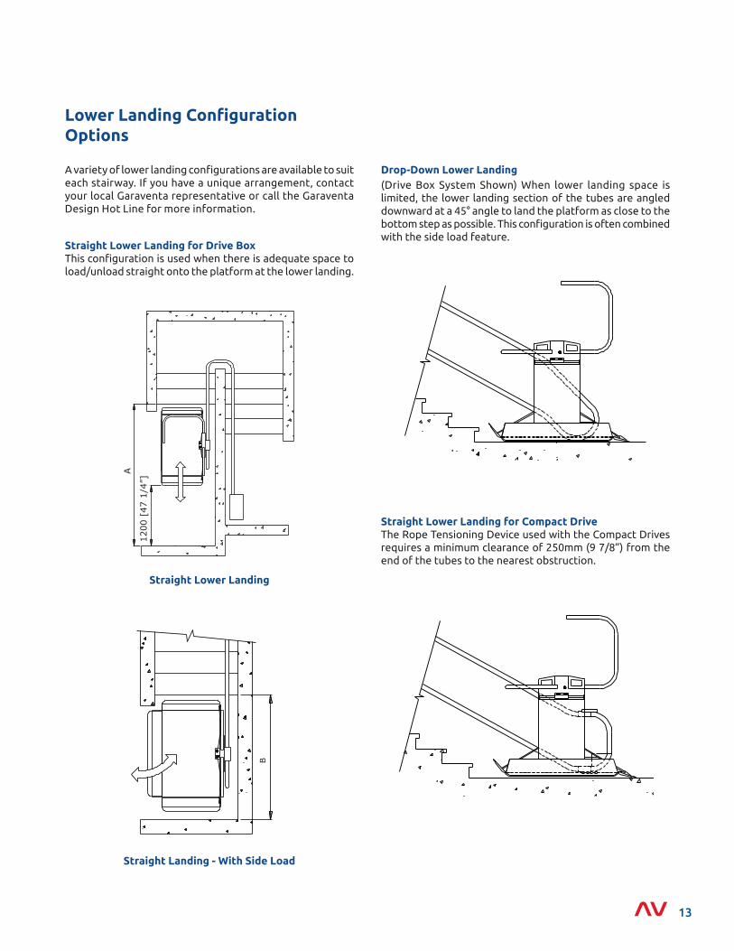
Lower Landing Configuration Options
(Drive Box System Shown) When lower landing space is limited, the lower landing section of the tubes are angled downward at a 45° angle to land the platform as close to the bottom step as possible. This configuration is often combined with the side load feature.
Straight Lower Landing for Compact DriveThe Rope Tensioning Device used with the Compact Drives requires a minimum clearance of 250mm (9 7/8”) from the end of the tubes to the nearest obstruction.
Straight Landing - With Side Load
B
Straight Lower Landing
1200
[47
1/4
”]
A
A variety of lower landing configurations are available to suit each stairway. If you have a unique arrangement, contact your local Garaventa representative or call the Garaventa Design Hot Line for more information.
Straight Lower Landing for Drive BoxThis configuration is used when there is adequate space to load/unload straight onto the platform at the lower landing.
Drop-Down Lower Landing
13
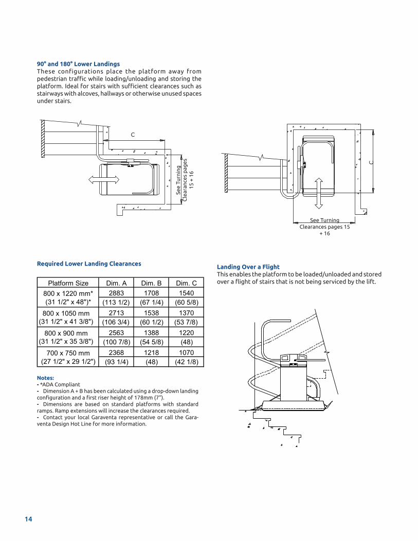
Notes:- *ADA Compliant- Dimension A + B has been calculated using a drop-down landing configuration and a first riser height of 178mm (7”).- Dimensions are based on standard platforms with standard ramps. Ramp extensions will increase the clearances required. - Contact your local Garaventa representative or call the Gara-venta Design Hot Line for more information.
Landing Over a FlightThis enables the platform to be loaded/unloaded and stored over a flight of stairs that is not being serviced by the lift.
90° and 180° Lower LandingsThese configurations place the platform away from pedestrian traffic while loading/unloading and storing the platform. Ideal for stairs with sufficient clearances such as stairways with alcoves, hallways or otherwise unused spaces under stairs.
Required Lower Landing Clearances
See Turning Clearances pages 15
+ 16
C
See
Turn
ing
C
lear
ance
s p
ages
15
+ 1
6
C
Platform Size Dim. A Dim. B Dim. C2883 1708 1540
(113 1/2) (67 1/4) (60 5/8)2713 1538 1370
(106 3/4) (60 1/2) (53 7/8)2563 1388 1220
(100 7/8) (54 5/8) (48)2368 1218 1070
(93 1/4) (48) (42 1/8)
800 x 1220 mm* (31 1/2" x 48")*
800 x 1050 mm (31 1/2" x 41 3/8")
800 x 900 mm (31 1/2" x 35 3/8")
700 x 750 mm (27 1/2" x 29 1/2")
14
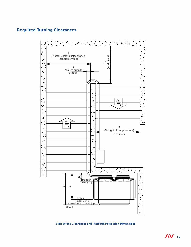
Stair Width Clearances and Platform Projection Dimensions
Required Turning Clearances
F(I
nsid
e B
end
)
AWall to outside
of tubes
B
CD
Side Load Ramp Loading (op-
tional)
PlatformFolded Down
PlatformFolded Up
E
(Straight Lift Applications)
No Bends
F (Note: Nearest obstruction.ie,
handrail or wall)
15
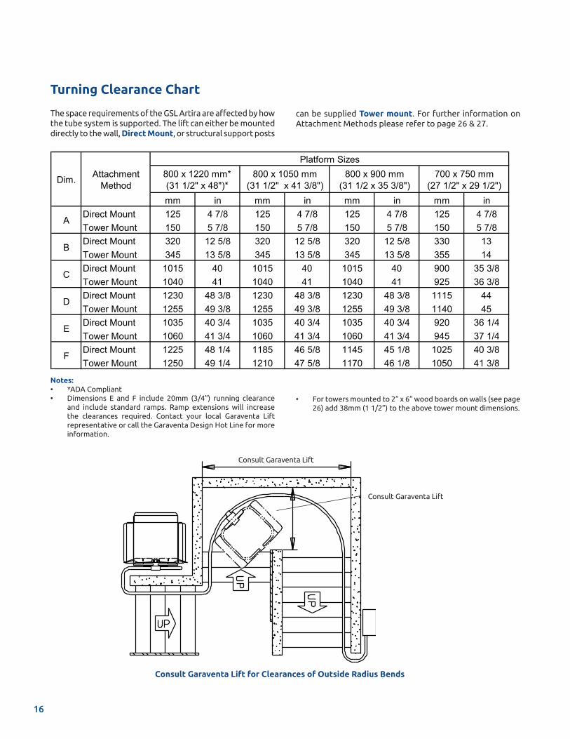
Notes: • *ADA Compliant• Dimensions E and F include 20mm (3/4”) running clearance
and include standard ramps. Ramp extensions will increase the clearances required. Contact your local Garaventa Lift representative or call the Garaventa Design Hot Line for more information.
Turning Clearance Chart
The space requirements of the GSL Artira are affected by how the tube system is supported. The lift can either be mounted directly to the wall, Direct Mount, or structural support posts
Consult Garaventa Lift
Consult Garaventa Lift
Consult Garaventa Lift for Clearances of Outside Radius Bends
mm in mm in mm in mm inDirect Mount 125 4 7/8 125 4 7/8 125 4 7/8 125 4 7/8Tower Mount 150 5 7/8 150 5 7/8 150 5 7/8 150 5 7/8Direct Mount 320 12 5/8 320 12 5/8 320 12 5/8 330 13Tower Mount 345 13 5/8 345 13 5/8 345 13 5/8 355 14Direct Mount 1015 40 1015 40 1015 40 900 35 3/8Tower Mount 1040 41 1040 41 1040 41 925 36 3/8Direct Mount 1230 48 3/8 1230 48 3/8 1230 48 3/8 1115 44Tower Mount 1255 49 3/8 1255 49 3/8 1255 49 3/8 1140 45Direct Mount 1035 40 3/4 1035 40 3/4 1035 40 3/4 920 36 1/4Tower Mount 1060 41 3/4 1060 41 3/4 1060 41 3/4 945 37 1/4Direct Mount 1225 48 1/4 1185 46 5/8 1145 45 1/8 1025 40 3/8Tower Mount 1250 49 1/4 1210 47 5/8 1170 46 1/8 1050 41 3/8
D
E
F
Platform Sizes
C
Attachment MethodDim.
A
B
800 x 1220 mm* (31 1/2" x 48")*
800 x 1050 mm (31 1/2" x 41 3/8")
800 x 900 mm (31 1/2 x 35 3/8")
700 x 750 mm (27 1/2" x 29 1/2")
• For towers mounted to 2” x 6” wood boards on walls (see page 26) add 38mm (1 1/2”) to the above tower mount dimensions.
can be supplied Tower mount. For further information on Attachment Methods please refer to page 26 & 27.
16
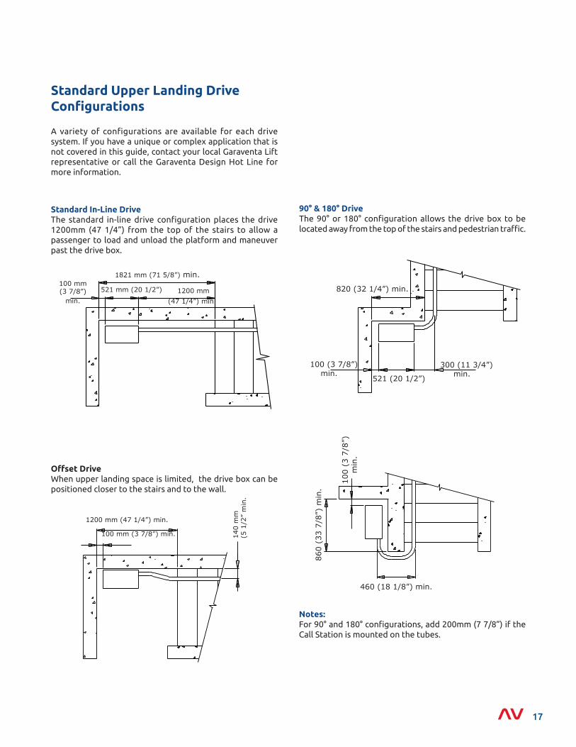
Offset DriveWhen upper landing space is limited, the drive box can be positioned closer to the stairs and to the wall.
Standard Upper Landing Drive Configurations
100 mm (3 7/8”)
1821 mm (71 5/8”) min.
1200 mmmin.
521 mm (20 1/2”)
(47 1/4”) min.
1200 mm (47 1/4”) min.
100 mm (3 7/8”) min. 140
mm
(5 1
/2”
min
.
Notes: For 90° and 180° configurations, add 200mm (7 7/8”) if the Call Station is mounted on the tubes.
90° & 180° DriveThe 90° or 180° configuration allows the drive box to be located away from the top of the stairs and pedestrian traffic.
300 (11 3/4”) min.
100 (3 7/8”) min.
820 (32 1/4”) min.
521 (20 1/2”)
460 (18 1/8”) min.
100
(3 7
/8”)
min
.
860
(33
7/8”
) m
in.
A variety of configurations are available for each drive system. If you have a unique or complex application that is not covered in this guide, contact your local Garaventa Lift representative or call the Garaventa Design Hot Line for more information.
Standard In-Line DriveThe standard in-line drive configuration places the drive 1200mm (47 1/4”) from the top of the stairs to allow a passenger to load and unload the platform and maneuver past the drive box.
17
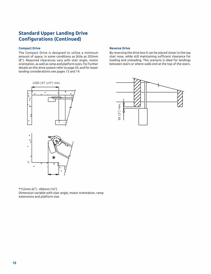
Compact DriveThe Compact Drive is designed to utilize a minimum amount of space, in some conditions as little as 203mm (8”). Required clearances vary with stair angle, motor orientation, as well as ramp and platform sizes. For further details on this drive system refer to page 20, and for lower landing considerations see pages 13 and 14.
Reverse DriveBy reversing the drive box it can be placed closer to the top stair nose, while still maintaining sufficient clearance for loading and unloading. This scenario is ideal for landings between stairs or where walls end at the top of the stairs.
*152mm (6”) - 406mm (16”)Dimension variable with stair angle, motor orientation, ramp extensions and platform size.
1200 (47 1/4”) min.
*
50 (
2”)
min
.
Standard Upper Landing Drive Configurations (Continued)
18
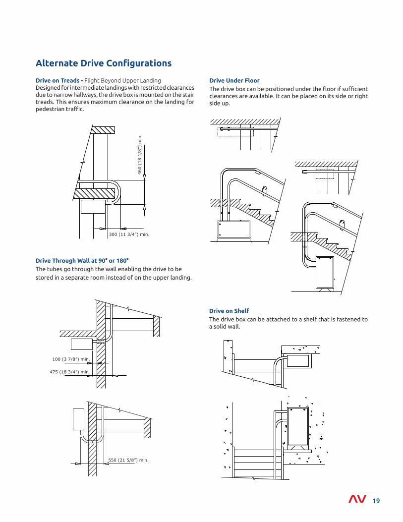
Drive on ShelfThe drive box can be attached to a shelf that is fastened to a solid wall.
Drive Under FloorThe drive box can be positioned under the floor if sufficient clearances are available. It can be placed on its side or right side up.
Drive Through Wall at 90° or 180°The tubes go through the wall enabling the drive to be stored in a separate room instead of on the upper landing.
475 (18 3/4”) min.
100 (3 7/8”) min.
550 (21 5/8”) min.
Alternate Drive Configurations
Drive on Treads - Flight Beyond Upper LandingDesigned for intermediate landings with restricted clearances due to narrow hallways, the drive box is mounted on the stair treads. This ensures maximum clearance on the landing for pedestrian traffic.
460
(18
1/8”
) m
in.
300 (11 3/4”) min.
19
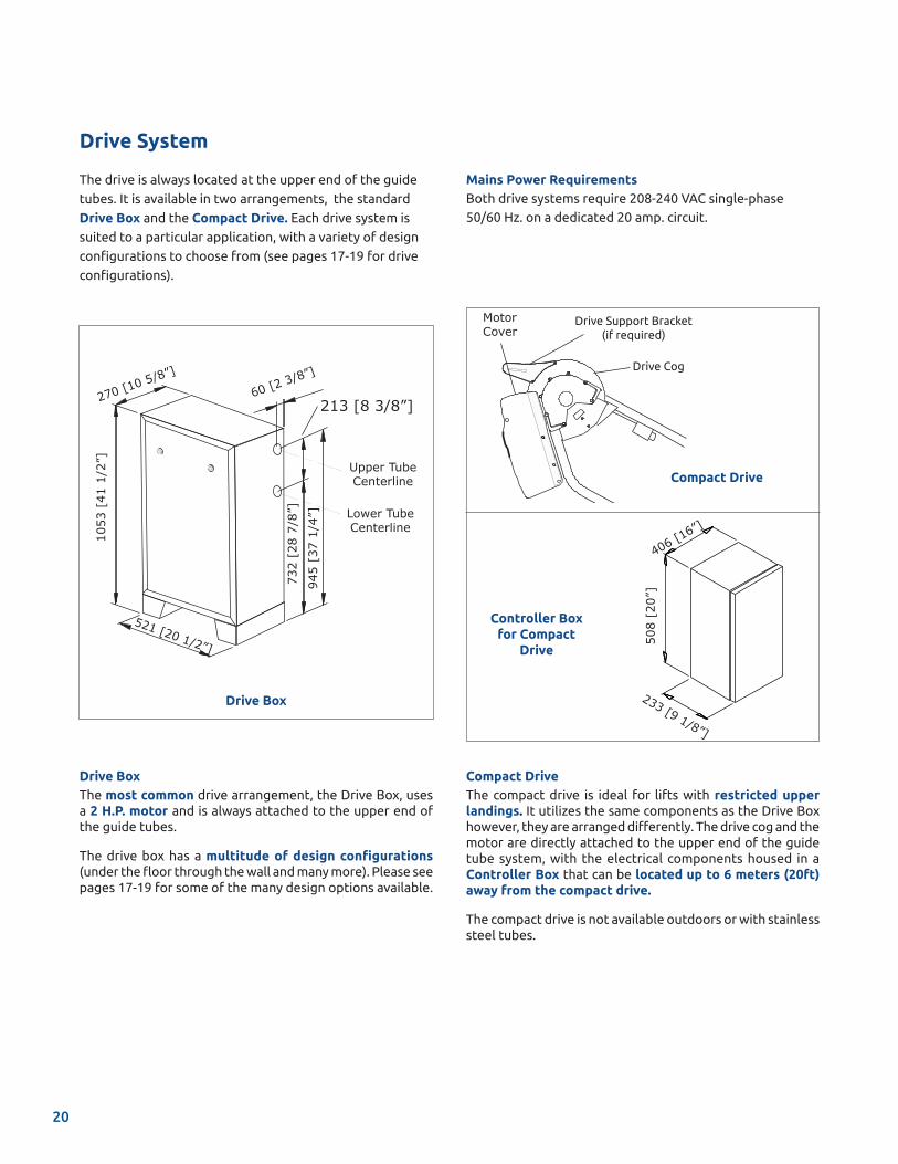
Compact DriveThe compact drive is ideal for lifts with restricted upper landings. It utilizes the same components as the Drive Box however, they are arranged differently. The drive cog and the motor are directly attached to the upper end of the guide tube system, with the electrical components housed in a Controller Box that can be located up to 6 meters (20ft) away from the compact drive.
The compact drive is not available outdoors or with stainless steel tubes.
The drive is always located at the upper end of the guide
tubes. It is available in two arrangements, the standard
Drive Box and the Compact Drive. Each drive system is
suited to a particular application, with a variety of design
configurations to choose from (see pages 17-19 for drive
configurations).
Drive BoxThe most common drive arrangement, the Drive Box, uses a 2 H.P. motor and is always attached to the upper end of the guide tubes.
The drive box has a multitude of design configurations (under the floor through the wall and many more). Please see pages 17-19 for some of the many design options available.
Compact Drive
406 [16”]
508
[20”
]
233 [9 1/8”]
Controller Box for Compact
Drive
Drive Support Bracket (if required)
Drive Cog
Motor Cover
Drive Box
1053
[41
1/2
”]
60 [2 3/8”]
732
[28
7/8”
]
945
[37
1/4”
]
213 [8 3/8”]
Upper Tube Centerline
Lower Tube Centerline
521 [20 1/2”]
270 [10 5/8”]
Drive System
Mains Power RequirementsBoth drive systems require 208-240 VAC single-phase 50/60 Hz. on a dedicated 20 amp. circuit.
20
The GSL Artira can be equipped with a number of additional safety features:
Audio Visual AlertA wall mounted strobe light and audible chime cautions pedestrians in the vicinity that the lift is in operation. The volume of the audible chime can be adjusted on site. This option is ideal for stairways with 90 degree or 180 degree switchbacks.
Fire Alarm Integration (Fire Service)The fire service feature is designed to interface with a building’s fire safety system and interrupt power to the lift when the fire alarm sounds. This ensures the lift will not obstruct stairway traffic during evacuation. If the lift is in use when the alarm sounds, the lift will only allow the platform to travel to the designated landing with the emergency exit. The passenger must use the constant pressure direction button. Custom versions of this feature are available. Consult Garaventa Lift.
Auxiliary Power SystemThis feature provides backup power to operate the lift when mains power is lost. The self contained battery unit can be located up to 4.5 meters (15’) away from the drive system.
Additional Component Options
Box Size: 597 mm (23 1/2”) high x 444 mm (17 1/2”) wide x 192 mm (7 5/8”) deep
Outdoor and Extreme ApplicationsWhen located outdoors or in extremely harsh environmental conditions, the lift will require a stainless steel drive box, stainless steel tubes, towers and audio visual alerts (if specified).
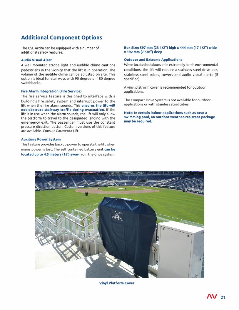
A vinyl platform cover is recommended for outdoor applications.
The Compact Drive System is not available for outdoor applications or with stainless steel tubes.
Note: In certain indoor applications such as near a swimming pool, an outdoor weather-resistant package may be required.
Vinyl Platform Cover
21
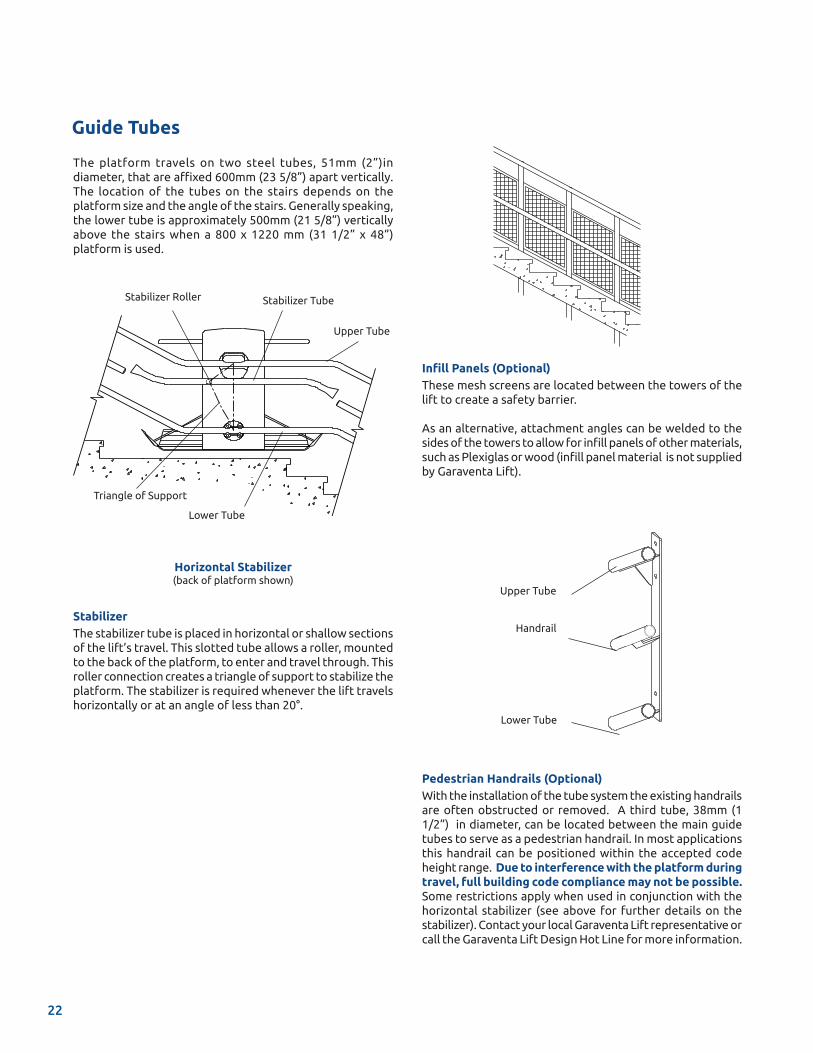
Stabilizer Roller Stabilizer Tube
Lower Tube
Triangle of Support
Upper Tube
The platform travels on two steel tubes, 51mm (2”)in diameter, that are affixed 600mm (23 5/8”) apart vertically. The location of the tubes on the stairs depends on the platform size and the angle of the stairs. Generally speaking, the lower tube is approximately 500mm (21 5/8”) vertically above the stairs when a 800 x 1220 mm (31 1/2” x 48”)platform is used.
Handrail
Upper Tube
Lower Tube
Guide Tubes
Horizontal Stabilizer(back of platform shown)
Infill Panels (Optional)These mesh screens are located between the towers of the lift to create a safety barrier.
As an alternative, attachment angles can be welded to the sides of the towers to allow for infill panels of other materials, such as Plexiglas or wood (infill panel material is not supplied by Garaventa Lift).
Pedestrian Handrails (Optional)With the installation of the tube system the existing handrails are often obstructed or removed. A third tube, 38mm (1 1/2”) in diameter, can be located between the main guide tubes to serve as a pedestrian handrail. In most applications this handrail can be positioned within the accepted code height range. Due to interference with the platform during travel, full building code compliance may not be possible. Some restrictions apply when used in conjunction with the horizontal stabilizer (see above for further details on the stabilizer). Contact your local Garaventa Lift representative or call the Garaventa Lift Design Hot Line for more information.
StabilizerThe stabilizer tube is placed in horizontal or shallow sections of the lift’s travel. This slotted tube allows a roller, mounted to the back of the platform, to enter and travel through. This roller connection creates a triangle of support to stabilize the platform. The stabilizer is required whenever the lift travels horizontally or at an angle of less than 20°.
22
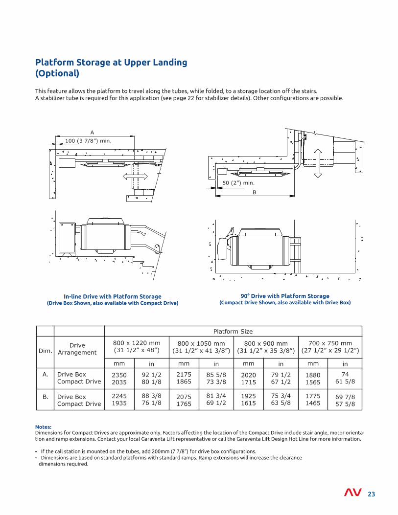
Platform Storage at Upper Landing (Optional)
90° Drive with Platform Storage (Compact Drive Shown, also available with Drive Box)
In-line Drive with Platform Storage (Drive Box Shown, also available with Compact Drive)
B
50 (2”) min.
This feature allows the platform to travel along the tubes, while folded, to a storage location off the stairs. A stabilizer tube is required for this application (see page 22 for stabilizer details). Other configurations are possible.
Notes:
A100 (3 7/8”) min.
Dimensions for Compact Drives are approximate only. Factors affecting the location of the Compact Drive include stair angle, motor orienta-tion and ramp extensions. Contact your local Garaventa Lift representative or call the Garaventa Lift Design Hot Line for more information.
- If the call station is mounted on the tubes, add 200mm (7 7/8”) for drive box configurations.- Dimensions are based on standard platforms with standard ramps. Ramp extensions will increase the clearance dimensions required.
23
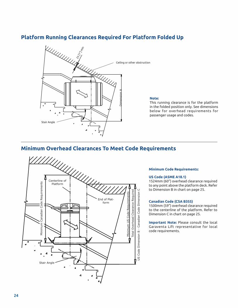
Platform Running Clearances Required For Platform Folded Up
Minimum Code Requirements:
US Code (ASME A18.1)1524mm (60”) overhead clearance required to any point above the platform deck. Refer to Dimension B in chart on page 25.
Canadian Code (CSA B355)1500mm (59”) overhead clearance required to the centerline of the platform. Refer to Dimension C in chart on page 25.
Important Note: Please consult the local Garaventa Lift representative for local code requirements.
Minimum Overhead Clearances To Meet Code Requirements
Stair Angle
Ceiling or other obstruction
Dim
ensi
on A
25 [1
”] m
in
Note:This running clearance is for the platform in the folded position only. See dimensions below for overhead requirements for passenger usage and codes.
Tota
l Ove
rhea
d Cle
aran
ce R
equi
red
Min
imum
US C
ode
Requ
irem
ents
Stair Angle
US C
ode
Dim
ensi
on B
- C
anad
ian
Cod
e D
imen
sion
C
Min
imum
Can
adia
n Cod
e Re
quirem
ents
End of Plat-form
Centerline of Platform
24
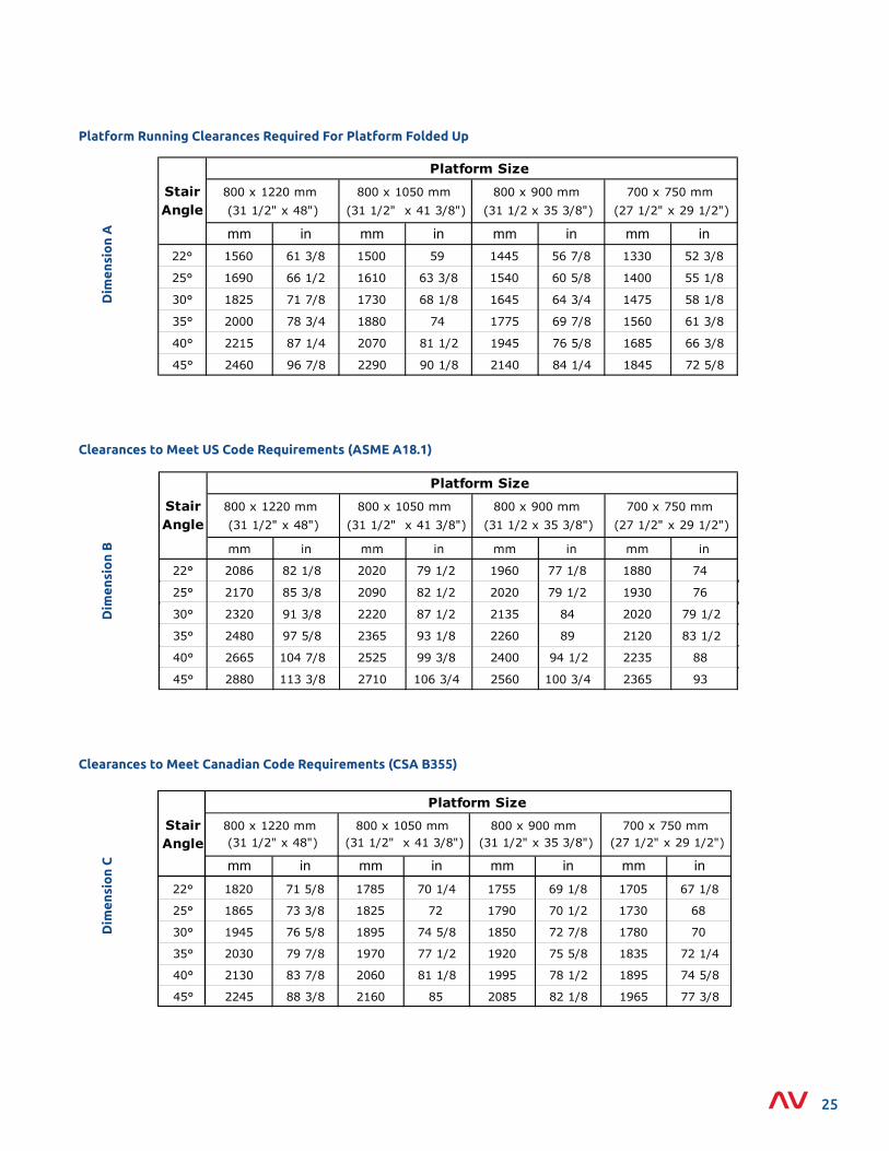
Clearances to Meet Canadian Code Requirements (CSA B355)
Dim
ensi
on
C mm in mm in mm in mm in22° 1820 71 5/8 1785 70 1/4 1755 69 1/8 1705 67 1/8
25° 1865 73 3/8 1825 72 1790 70 1/2 1730 68
30° 1945 76 5/8 1895 74 5/8 1850 72 7/8 1780 70
35° 2030 79 7/8 1970 77 1/2 1920 75 5/8 1835 72 1/4
40° 2130 83 7/8 2060 81 1/8 1995 78 1/2 1895 74 5/8
45° 2245 88 3/8 2160 85 2085 82 1/8 1965 77 3/8
700 x 750 mm (27 1/2" x 29 1/2")
Stair Angle
800 x 1220 mm (31 1/2" x 48")
800 x 1050 mm (31 1/2" x 41 3/8")
800 x 900 mm (31 1/2" x 35 3/8")
Platform Size
Platform Running Clearances Required For Platform Folded Up
Dim
ensi
on
A mm in mm in mm in mm in22° 1560 61 3/8 1500 59 1445 56 7/8 1330 52 3/8
25° 1690 66 1/2 1610 63 3/8 1540 60 5/8 1400 55 1/8
30° 1825 71 7/8 1730 68 1/8 1645 64 3/4 1475 58 1/8
35° 2000 78 3/4 1880 74 1775 69 7/8 1560 61 3/8
40° 2215 87 1/4 2070 81 1/2 1945 76 5/8 1685 66 3/8
45° 2460 96 7/8 2290 90 1/8 2140 84 1/4 1845 72 5/8
700 x 750 mm
(27 1/2" x 29 1/2")
Stair Angle
800 x 1220 mm
(31 1/2" x 48")
800 x 1050 mm
(31 1/2" x 41 3/8")
800 x 900 mm
(31 1/2 x 35 3/8")
Platform Size
Clearances to Meet US Code Requirements (ASME A18.1)
Dim
ensi
on
B mm in mm in mm in mm in
22° 2086 82 1/8 2020 79 1/2 1960 77 1/8 1880 74
25° 2170 85 3/8 2090 82 1/2 2020 79 1/2 1930 76
30° 2320 91 3/8 2220 87 1/2 2135 84 2020 79 1/2
35° 2480 97 5/8 2365 93 1/8 2260 89 2120 83 1/2
40° 2665 104 7/8 2525 99 3/8 2400 94 1/2 2235 88
45° 2880 113 3/8 2710 106 3/4 2560 100 3/4 2365 93
700 x 750 mm
(27 1/2" x 29 1/2")
Stair Angle
800 x 1220 mm
(31 1/2" x 48")
800 x 1050 mm
(31 1/2" x 41 3/8")
800 x 900 mm
(31 1/2 x 35 3/8")
Platform Size
25
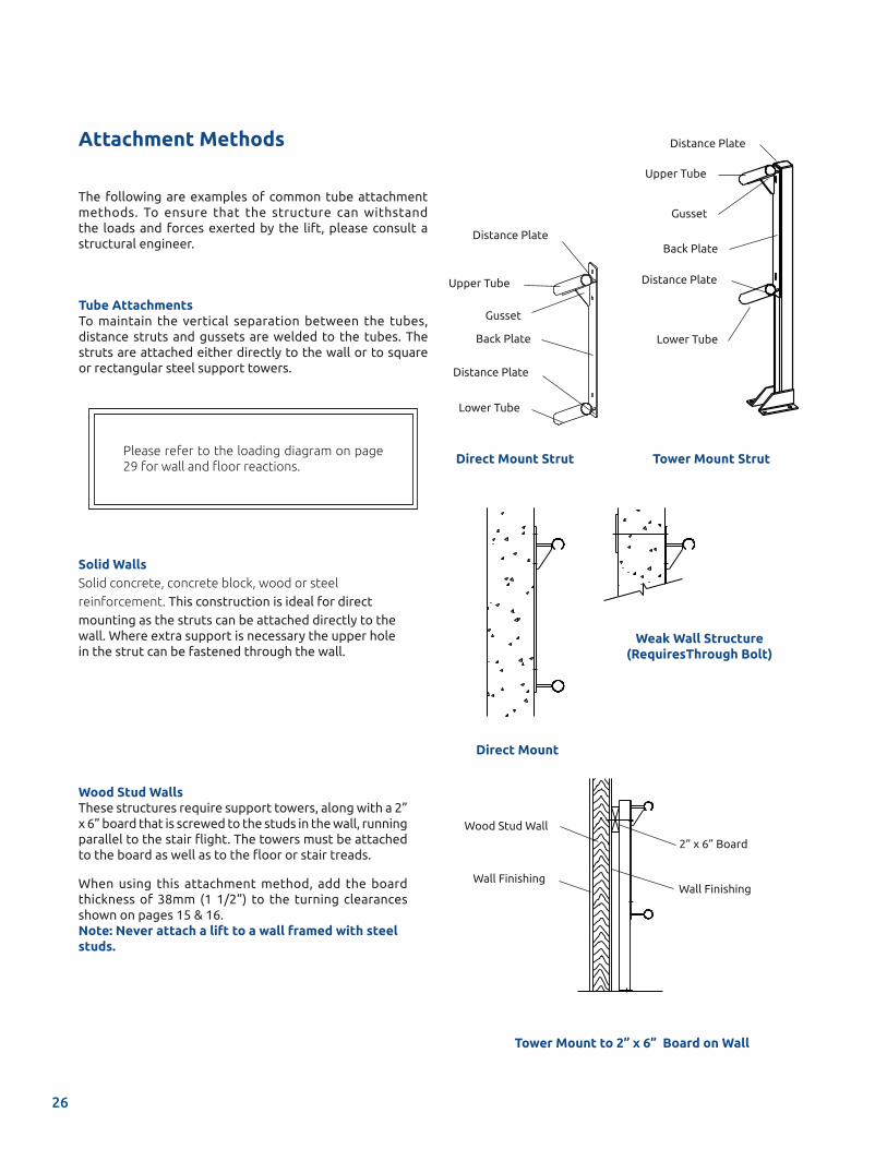
Wood Stud Walls These structures require support towers, along with a 2” x 6” board that is screwed to the studs in the wall, running parallel to the stair flight. The towers must be attached to the board as well as to the floor or stair treads.
When using this attachment method, add the board thickness of 38mm (1 1/2”) to the turning clearances shown on pages 15 & 16.Note: Never attach a lift to a wall framed with steel studs.
Attachment Methods
Tower Mount StrutDirect Mount Strut
Tower Mount to 2” x 6” Board on Wall
Upper Tube
Gusset
Back Plate
Distance Plate
Lower Tube
Distance Plate
Distance Plate
Lower Tube
Back Plate
Gusset
Upper Tube
Distance Plate
2” x 6” Board
Wood Stud Wall
Wall FinishingWall Finishing
Direct Mount
Weak Wall Structure (RequiresThrough Bolt)
Solid Walls Solid concrete, concrete block, wood or steel reinforcement. This construction is ideal for direct mounting as the struts can be attached directly to the wall. Where extra support is necessary the upper hole in the strut can be fastened through the wall.
Please refer to the loading diagram on page 29 for wall and floor reactions.
Tube AttachmentsTo maintain the vertical separation between the tubes, distance struts and gussets are welded to the tubes. The struts are attached either directly to the wall or to square or rectangular steel support towers.
The following are examples of common tube attachment methods. To ensure that the structure can withstand the loads and forces exerted by the lift, please consult a structural engineer.
26
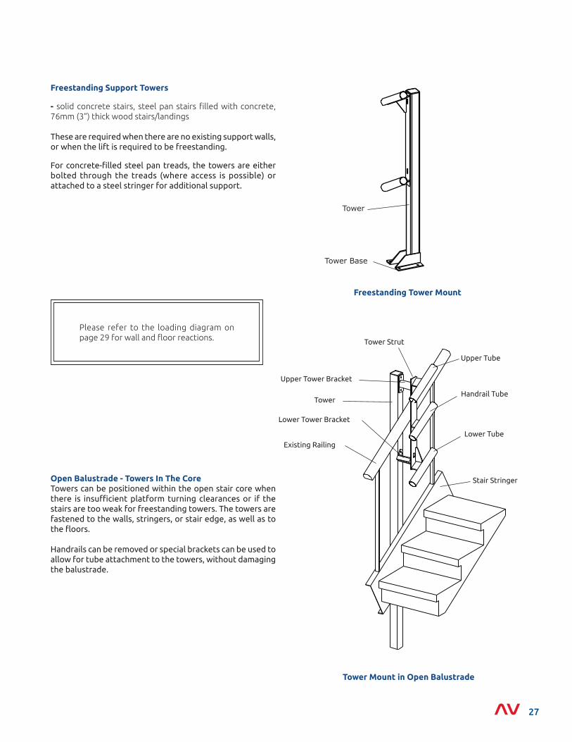
Freestanding Support Towers
- solid concrete stairs, steel pan stairs filled with concrete, 76mm (3”) thick wood stairs/landings
These are required when there are no existing support walls, or when the lift is required to be freestanding.
For concrete-filled steel pan treads, the towers are either bolted through the treads (where access is possible) or attached to a steel stringer for additional support.
Freestanding Tower Mount
Tower Mount in Open Balustrade
Open Balustrade - Towers In The CoreTowers can be positioned within the open stair core when there is insufficient platform turning clearances or if the stairs are too weak for freestanding towers. The towers are fastened to the walls, stringers, or stair edge, as well as to the floors.
Handrails can be removed or special brackets can be used to allow for tube attachment to the towers, without damaging the balustrade.
Tower
Tower Base
Lower Tube
Existing Railing
Lower Tower Bracket
Tower
Upper Tube
Tower Strut
Stair Stringer
Upper Tower Bracket
Handrail Tube
Please refer to the loading diagram on page 29 for wall and floor reactions.
27
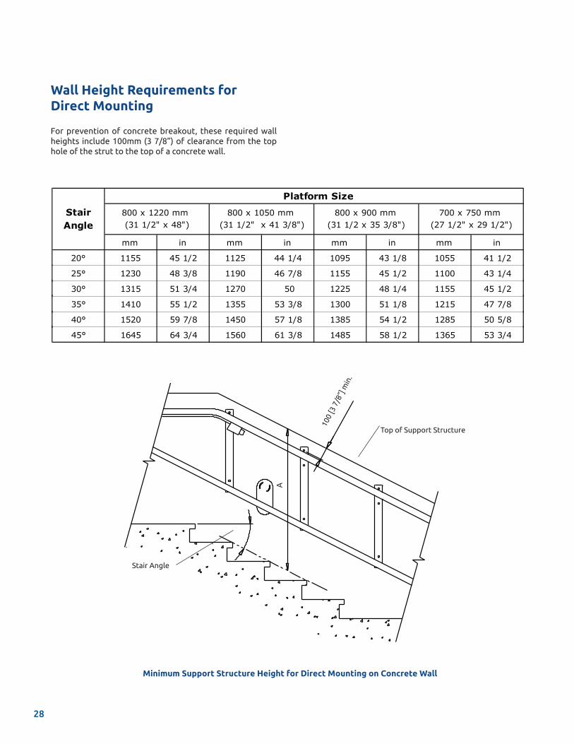
Minimum Support Structure Height for Direct Mounting on Concrete Wall
For prevention of concrete breakout, these required wall heights include 100mm (3 7/8”) of clearance from the top hole of the strut to the top of a concrete wall.
mm in mm in mm in mm in
20° 1155 45 1/2 1125 44 1/4 1095 43 1/8 1055 41 1/2
25° 1230 48 3/8 1190 46 7/8 1155 45 1/2 1100 43 1/4
30° 1315 51 3/4 1270 50 1225 48 1/4 1155 45 1/2
35° 1410 55 1/2 1355 53 3/8 1300 51 1/8 1215 47 7/8
40° 1520 59 7/8 1450 57 1/8 1385 54 1/2 1285 50 5/8
45° 1645 64 3/4 1560 61 3/8 1485 58 1/2 1365 53 3/4
800 x 900 mm (31 1/2 x 35 3/8")
700 x 750 mm (27 1/2" x 29 1/2")
Stair Angle
800 x 1220 mm (31 1/2" x 48")
800 x 1050 mm (31 1/2" x 41 3/8")
Platform Size
Top of Support Structure
100
[3 7
/8”]
min
.
A
Stair Angle
Wall Height Requirements for Direct Mounting
28
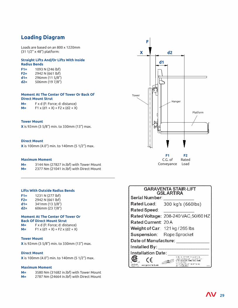
Loads are based on an 800 x 1220mm (31 1/2” x 48”) platform:
Straight Lifts And/Or Lifts With Inside Radius BendsF1= 1093 N (246 lbf)F2= 2942 N (661 lbf)d1= 296mm (11 5/8”) d2= 506mm (19 7/8”)
Moment At The Center Of Tower Or Back Of Direct Mount StrutM= F x d (F: Force; d: distance) M= F1 x (d1 + X) + F2 x (d2 + X)
Tower MountX is 92mm (3 5/8”) min. to 330mm (13”) max.
Direct MountX is 100mm (4.0”) min. to 140mm (5 1/2”) max.
Maximum MomentM= 3144 Nm (27827 in.lbf) with Tower Mount M= 2377 Nm (21041 in.lbf) with Direct Mount
Loading DiagramF
X d2
d1
Hanger
F2 Rated Load
F1 C.G. of
Conveyance
Platform
Tower
300 kg’s (660lbs)
Lifts With Outside Radius BendsF1= 1231 N (277 lbf)F2= 2942 N (661 lbf)d1= 341mm (13 3/8”) d2= 606mm (23 7/8”)
Moment At The Center Of Tower Or Back Of Direct Mount StrutM= F x d (F: Force; d: distance)M= F1 x (d1 + X) + F2 x (d2 + X)
Tower MountX is 92mm (3 5/8”) min. to 330mm (13”) max.
Direct MountX is 100mm (4.0”) min. to 140mm (5 1/2”) max.
Maximum MomentM= 3580 Nm (31682 in.lbf) with Tower Mount M= 2787 Nm (24664 in.lbf) with Direct Mount
29
Platform Sizes800 x 1220mm (31 1/2” x 48”) - ADA Compliant 800 x 1050mm (31 1/2” x 41 3/8”)800 x 900mm (31 1/2” x 35 3/8”)700 x 750mm (27 1/2” x 29 1/2”)
Curved Safety Arms
Fully automatic, 32mm (1 1/4”) diameter safety arms, top of arm 948mm (37 3/8”) above platform deck.
Pedestrian Safety Lights
Illuminated tube lighting, located at both ends of the plat-form deck. Alerts pedestrians that the platform is in motion.
Rated Load300 kg. (660 lbs.)
Speed
6 meters (20 ft) per minute, slowing to 3 meters (10 ft) through corners and when approaching or departing landings.
Operating Controls
Call Stations (Standard): Equipped with Garaventa Lift Smart-Lite Technology™, constant pressure directional buttons, one touch fold & unfold buttons, 24VDC power, and keyed operation.
Platform (Standard): Equipped with constant pressure switches, Emergency Stop Button (manual reset) and key-less operation
Technical Reference of Standard Features
Drive System
Motor: Single phase (supplied by inverter) 2 H.P. drive box at the end of the guide tube system. The drive box can be located away from the upper landing by extending the guide tubes.
Power Requirements: The mains power requirement for both drive systems is 208-240 VAC, 50/60 HZ single phase on a dedicated 20 amp. circuit.
Power Transmission: Roped sprocket using 8mm (3/8”) wire haul rope.
Emergency Use: Ratchet wrench (or handwheel) is provided.
Daily Cycles:
Your Artira is designed based on the following daily cycles:
• Normal 10
• Heavy 30
• Excessive 45
• Max. starts per hour 5
Consult your Sales Representative if there is a chance you may exceed these amounts.
Overspeed SafetyLocated at the bottom of the tube assembly containing mechanical overspeed sensor and brake, with electrical drive cut-out protection.
Rail System
Two 51mm (2”) O.D. steel tubes spaced 600mm (23 5/8”) apart vertically.
Finishes
Durable electrostatically applied and baked fine textured Satin Grey paint.
30
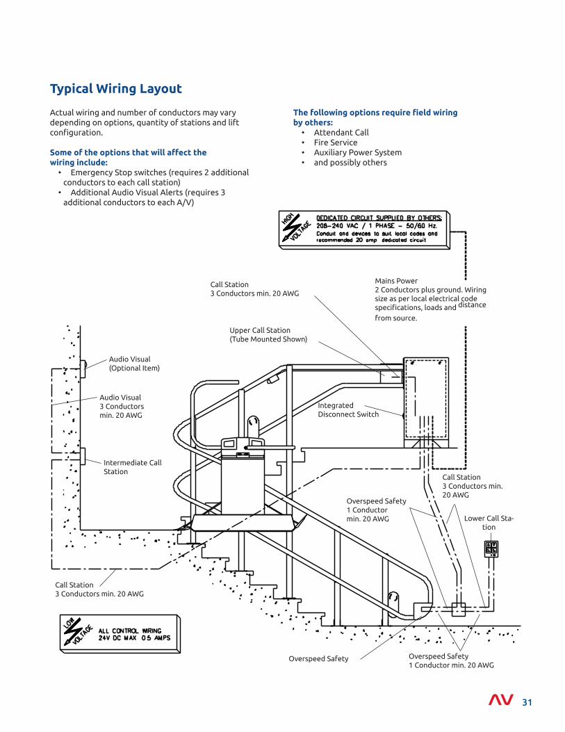
Mains Power2 Conductors plus ground. Wiring size as per local electrical code specifications, loads and distance
from source.
Overspeed Safety1 Conductor min. 20 AWG
Overspeed Safety
Call Station3 Conductors min. 20 AWG
Lower Call Sta-tion
Call Station3 Conductors min. 20 AWG
Upper Call Station(Tube Mounted Shown)
Intermediate Call Station
Audio Visual(Optional Item)
Audio Visual 3 Conductors min. 20 AWG
Overspeed Safety1 Conductormin. 20 AWG
Call Station3 Conductors min. 20 AWG
Integrated Disconnect Switch
Actual wiring and number of conductors may vary depending on options, quantity of stations and lift configuration.
Some of the options that will affect thewiring include: • Emergency Stop switches (requires 2 additional conductors to each call station) • Additional Audio Visual Alerts (requires 3 additional conductors to each A/V)
Typical Wiring Layout
The following options require field wiring by others: • Attendant Call • Fire Service • Auxiliary Power System • and possibly others
31
Garaventa LiftT 800 663 6556 (toll free North America) E [email protected] · I www.garaventalift.com
© Garaventa Lift. As we are continuously improving our products , specif icat ions outlined in this brochure are subject to change without notice.
15810-O01-DP-ENAuthorized Garaventa Lift Representative