Embed Size (px)
Citation preview
ELS-7500EX ECA Training Manual
Elionix Inc.
2. Pattern Creation from DXF data

1
Starting the Program User accounts are set by default as shown below. 1. Limited User
Login account “ELS-7500” Password “ELS75”
2. Administrator
Login account “Administrator” Password “ELS75”
Normally, the “ELS-7500” limited user account should be entered. Note that WecaS can not be started unless the SEM PC side system has been started. Always check before attempting to start WecaS.
2
Format conversion +
Chip positioning
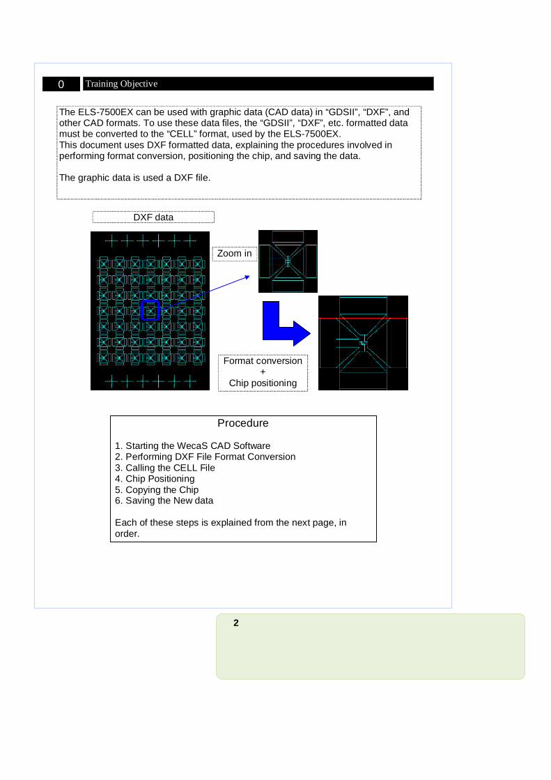
The ELS-7500EX can be used with graphic data (CAD data) in “GDSII”, “DXF”, and other CAD formats. To use these data files, the “GDSII”, “DXF”, etc. formatted data must be converted to the “CELL” format, used by the ELS-7500EX. This document uses DXF formatted data, explaining the procedures involved in performing format conversion, positioning the chip, and saving the data. The graphic data is used a DXF file.
0 Training Objective
Procedure 1. Starting the WecaS CAD Software 2. Performing DXF File Format Conversion 3. Calling the CELL File 4. Chip Positioning 5. Copying the Chip 6. Saving the New data Each of these steps is explained from the next page, in order.
DXF data
Zoom in
3
Procedure:
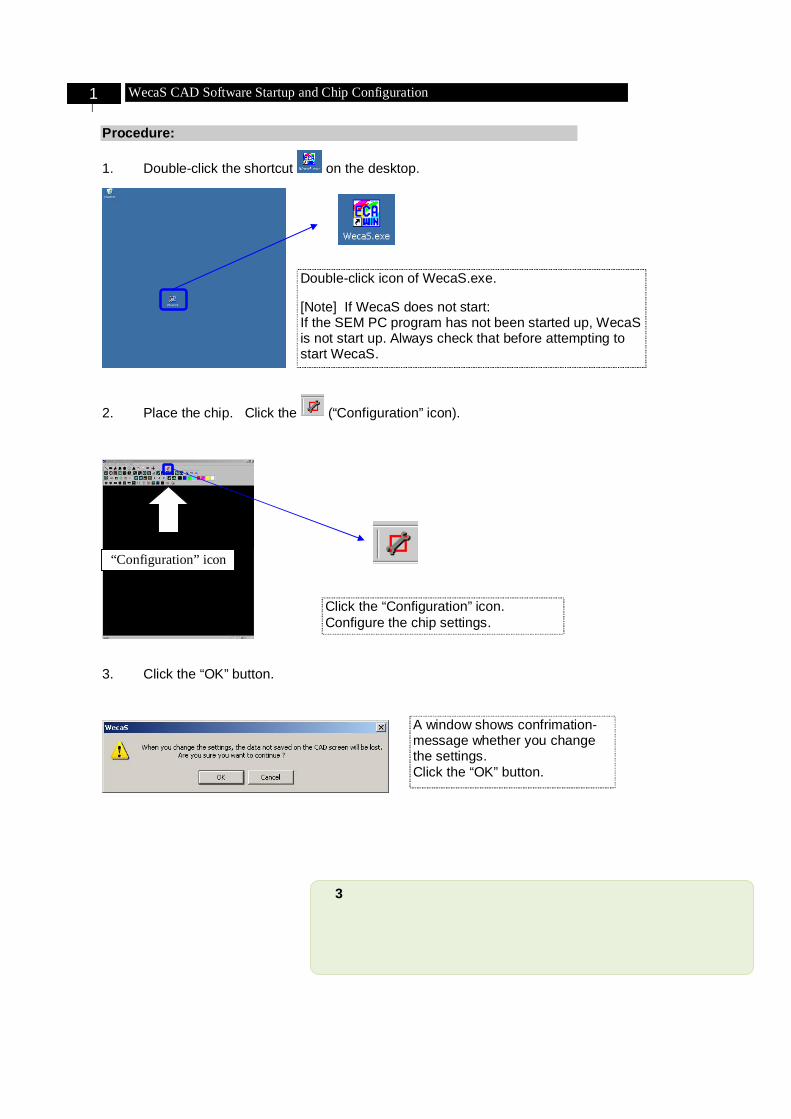
1. Double-click the shortcut on the desktop.
2. Place the chip. Click the (“Configuration” icon).
3. Click the “OK” button.
Double-click icon of WecaS.exe. [Note] If WecaS does not start: If the SEM PC program has not been started up, WecaS is not start up. Always check that before attempting to start WecaS.
“Configuration” icon
Click the “Configuration” icon. Configure the chip settings.
A window shows confrimation-message whether you change the settings. Click the “OK” button.
1 WecaS CAD Software Startup and Chip Configuration
4
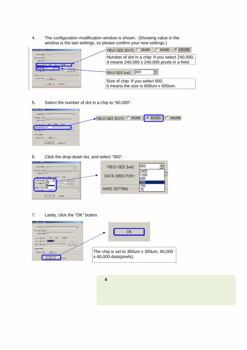
4. The configuration modification window is shown. (Showing value in the window is the last settings, so please confirm your new settings.)
5. Select the number of dot in a chip to “60,000”.
6. Click the drop-down list, and select “300”.
7. Lastly, click the “OK” button.
The chip is set to 300um x 300um, 60,000 x 60,000 dots(pixels).
Number of dot in a chip: If you select 240,000, it means 240,000 x 240,000 pixels in a field.
Size of chip: If you select 600, it means the size is 600um x 600um.
5
Procedure:
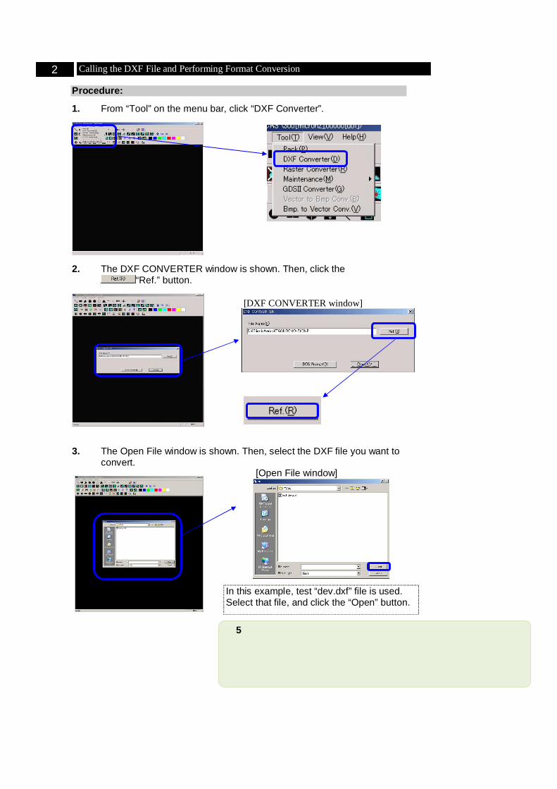
1. From “Tool” on the menu bar, click “DXF Converter”.
2. The DXF CONVERTER window is shown. Then, click the “Ref.” button.
3. The Open File window is shown. Then, select the DXF file you want to convert.
2 Calling the DXF File and Performing Format Conversion
In this example, test “dev.dxf” file is used. Select that file, and click the “Open” button.
[DXF CONVERTER window]
[Open File window]
6
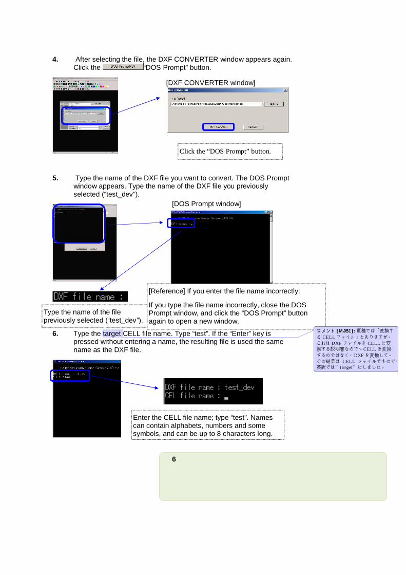
4. After selecting the file, the DXF CONVERTER window appears again. Click the “DOS Prompt” button.
5. Type the name of the DXF file you want to convert. The DOS Prompt window appears. Type the name of the DXF file you previously selected (“test_dev”).
6. Type the target CELL file name. Type “test”. If the “Enter” key is pressed without entering a name, the resulting file is used the same name as the DXF file.
Type the name of the file previously selected (“test_dev”).
[Reference] If you enter the file name incorrectly:
If you type the file name incorrectly, close the DOS Prompt window, and click the “DOS Prompt” button again to open a new window.
Enter the CELL file name; type “test”. Names can contain alphabets, numbers and some symbols, and can be up to 8 characters long.
Click the “DOS Prompt” button.
[DXF CONVERTER window]
[DOS Prompt window]
コメント [MJB1]: 原稿では「変換する CELLファイル」とありますが、これは DXFファイルを CELLに変換する説明書なので、CELLを変換するのではなく、DXFを変換して、その結果は CELL ファイルですので、英訳では”target”にしました。
7
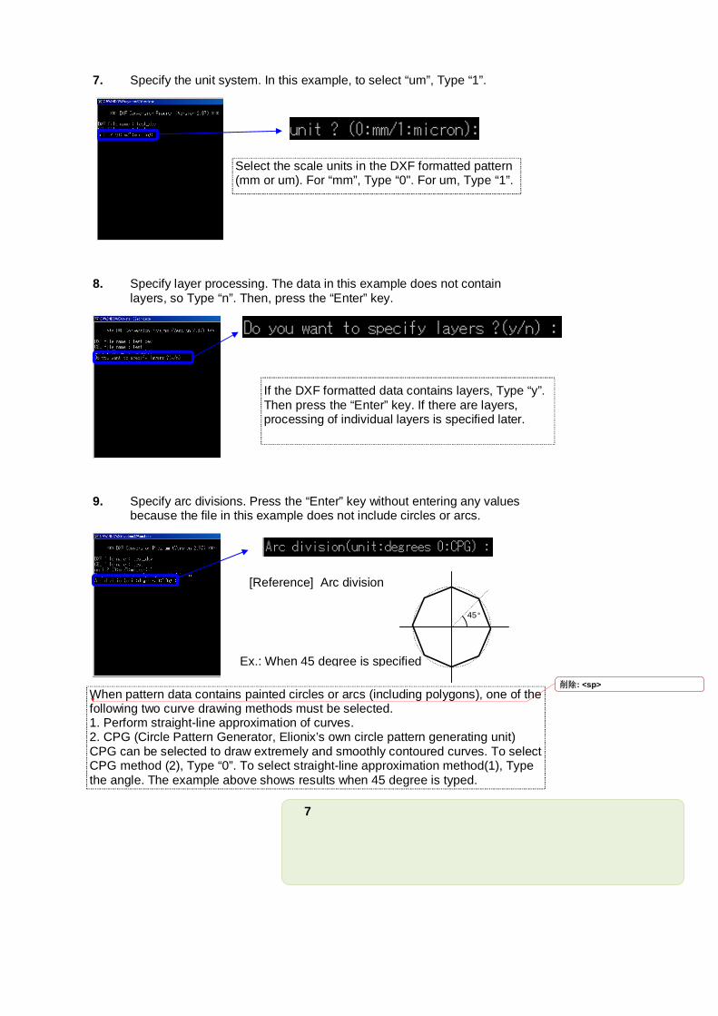
7. Specify the unit system. In this example, to select “um”, Type “1”.
8. Specify layer processing. The data in this example does not contain layers, so Type “n”. Then, press the “Enter” key.
9. Specify arc divisions. Press the “Enter” key without entering any values because the file in this example does not include circles or arcs.
Select the scale units in the DXF formatted pattern (mm or um). For “mm”, Type “0". For um, Type “1”.
If the DXF formatted data contains layers, Type “y”. Then press the “Enter” key. If there are layers, processing of individual layers is specified later.
When pattern data contains painted circles or arcs (including polygons), one of the following two curve drawing methods must be selected. 1. Perform straight-line approximation of curves. 2. CPG (Circle Pattern Generator, Elionix’s own circle pattern generating unit) CPG can be selected to draw extremely and smoothly contoured curves. To select CPG method (2), Type “0”. To select straight-line approximation method(1), Type the angle. The example above shows results when 45 degree is typed.
Ex.: When 45 degree is specified
45°
[Reference] Arc division
削除: <sp>
8
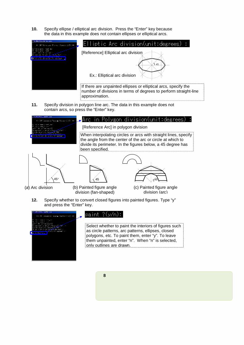
10. Specify ellipse / elliptical arc division. Press the “Enter” key because the data in this example does not contain ellipses or elliptical arcs.
11. Specify division in polygon line arc. The data in this example does not contain arcs, so press the “Enter” key.
12. Specify whether to convert closed figures into painted figures. Type “y” and press the “Enter” key.
If there are unpainted ellipses or elliptical arcs, specify the number of divisions in terms of degrees to perform straight-line approximation.
Select whether to paint the interiors of figures such as circle patterns, arc patterns, ellipses, closed polygons, etc. To paint them, enter “y”. To leave them unpainted, enter “n”. When “n” is selected, only outlines are drawn.
Ex.: Elliptical arc division
45
When interpolating circles or arcs with straight lines, specify the angle from the center of the arc or circle at which to divide its perimeter. In the figures below, a 45 degree has been specified.
45°
(a) Arc division
45°
(b) Painted figure angle division (fan-shaped)
45°
(c) Painted figure angle division (arc)
[Reference] Elliptical arc division
[Reference Arc] in polygon division
9
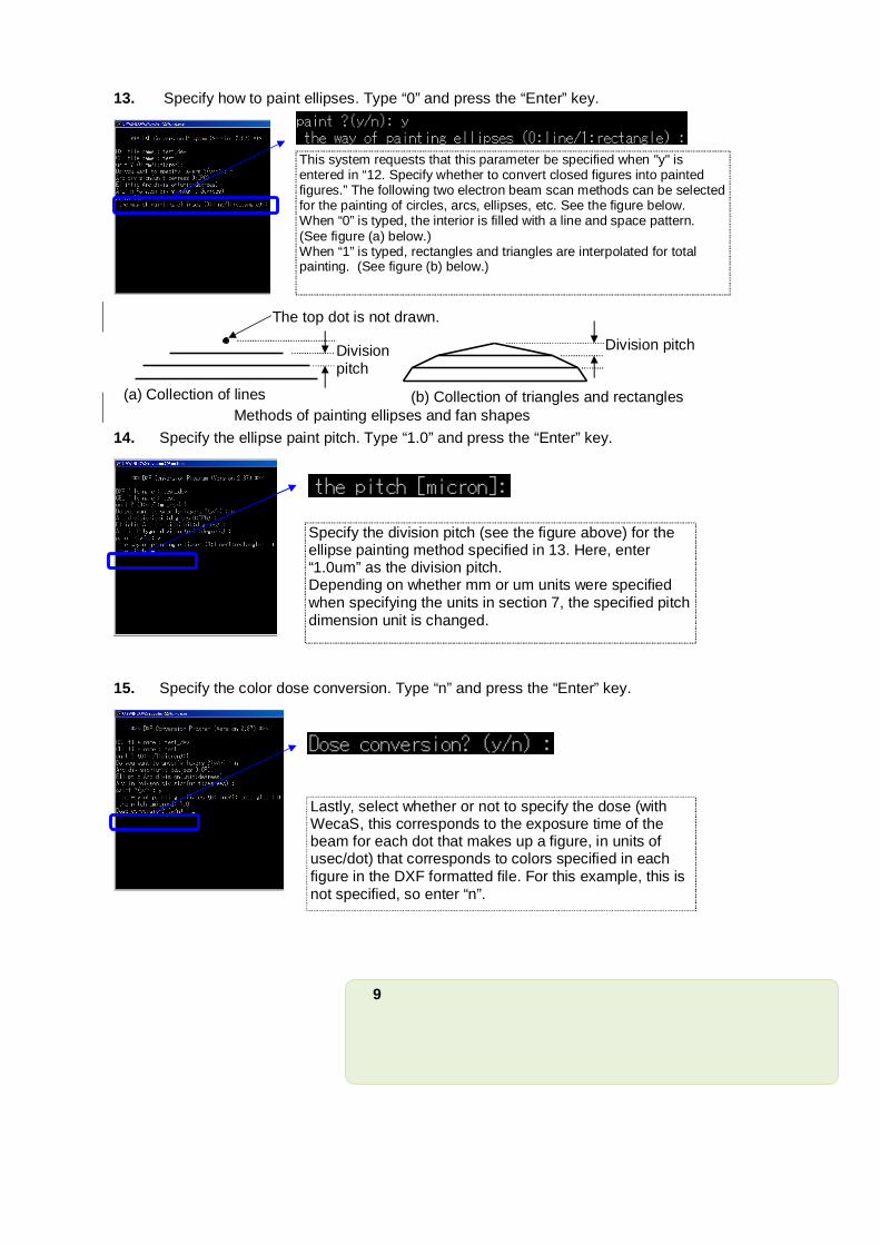
13. Specify how to paint ellipses. Type “0” and press the “Enter” key.
14. Specify the ellipse paint pitch. Type “1.0” and press the “Enter” key.
15. Specify the color dose conversion. Type “n” and press the “Enter” key.
This system requests that this parameter be specified when "y" is entered in “12. Specify whether to convert closed figures into painted figures.” The following two electron beam scan methods can be selected for the painting of circles, arcs, ellipses, etc. See the figure below. When “0” is typed, the interior is filled with a line and space pattern. (See figure (a) below.) When “1” is typed, rectangles and triangles are interpolated for total painting. (See figure (b) below.)
Specify the division pitch (see the figure above) for the ellipse painting method specified in 13. Here, enter “1.0um” as the division pitch. Depending on whether mm or um units were specified when specifying the units in section 7, the specified pitch dimension unit is changed.
Lastly, select whether or not to specify the dose (with WecaS, this corresponds to the exposure time of the beam for each dot that makes up a figure, in units of usec/dot) that corresponds to colors specified in each figure in the DXF formatted file. For this example, this is not specified, so enter “n”.
Division pitch
(b) Collection of triangles and rectangles
Division pitch
The top dot is not drawn.
(a) Collection of lines
Methods of painting ellipses and fan shapes
10
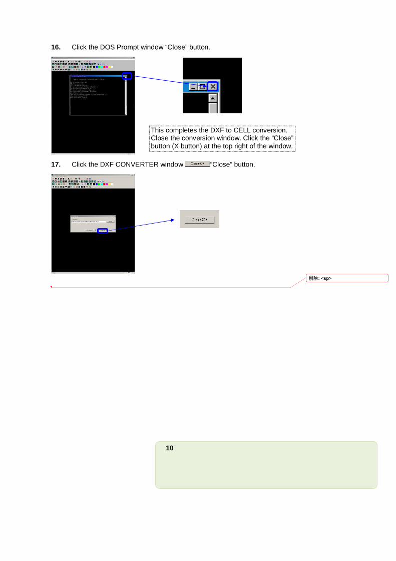
16. Click the DOS Prompt window “Close” button.
17. Click the DXF CONVERTER window “Close” button.
This completes the DXF to CELL conversion. Close the conversion window. Click the “Close” button (X button) at the top right of the window.
削除: <sp>
11
Procedure:
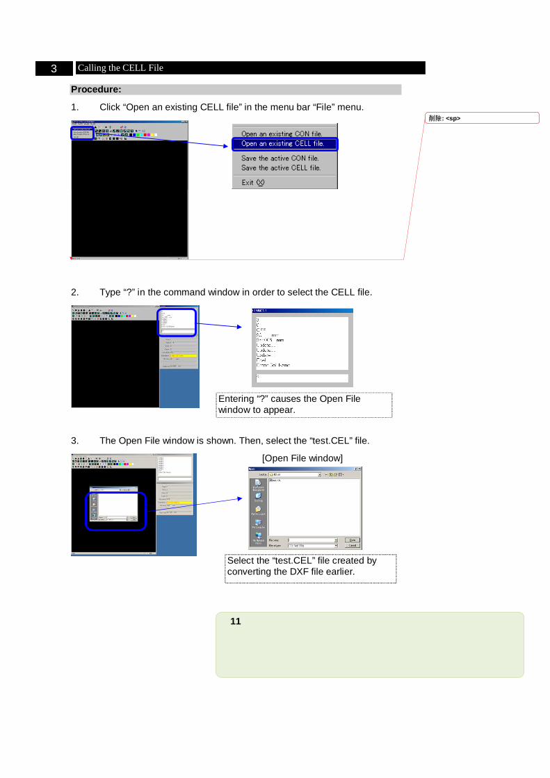
1. Click “Open an existing CELL file” in the menu bar “File” menu.
2. Type “?” in the command window in order to select the CELL file.
3. The Open File window is shown. Then, select the “test.CEL” file.
3 Calling the CELL File
Entering “?” causes the Open File window to appear.
Select the “test.CEL” file created by converting the DXF file earlier.
[Open File window]
削除: <sp>
12
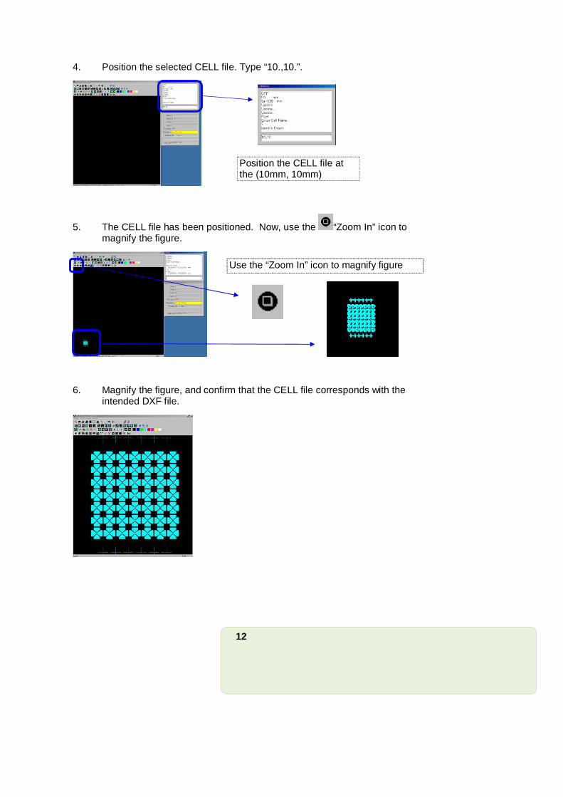
4. Position the selected CELL file. Type “10.,10.”.
5. The CELL file has been positioned. Now, use the “Zoom In” icon to magnify the figure.
6. Magnify the figure, and confirm that the CELL file corresponds with the intended DXF file.
Position the CELL file at the (10mm, 10mm) location.
Use the “Zoom In” icon to magnify figure
13
Procedure:
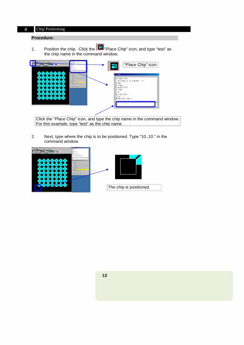
1. Position the chip. Click the “Place Chip” icon, and type “test” as the chip name in the command window.
2. Next, type where the chip is to be positioned. Type “10.,10.” in the command window.
4 Chip Positioning
Click the “Place Chip” icon, and type the chip name in the command window. For this example, type “test” as the chip name.
The chip is positioned.
“Place Chip” icon
14
Procedure:
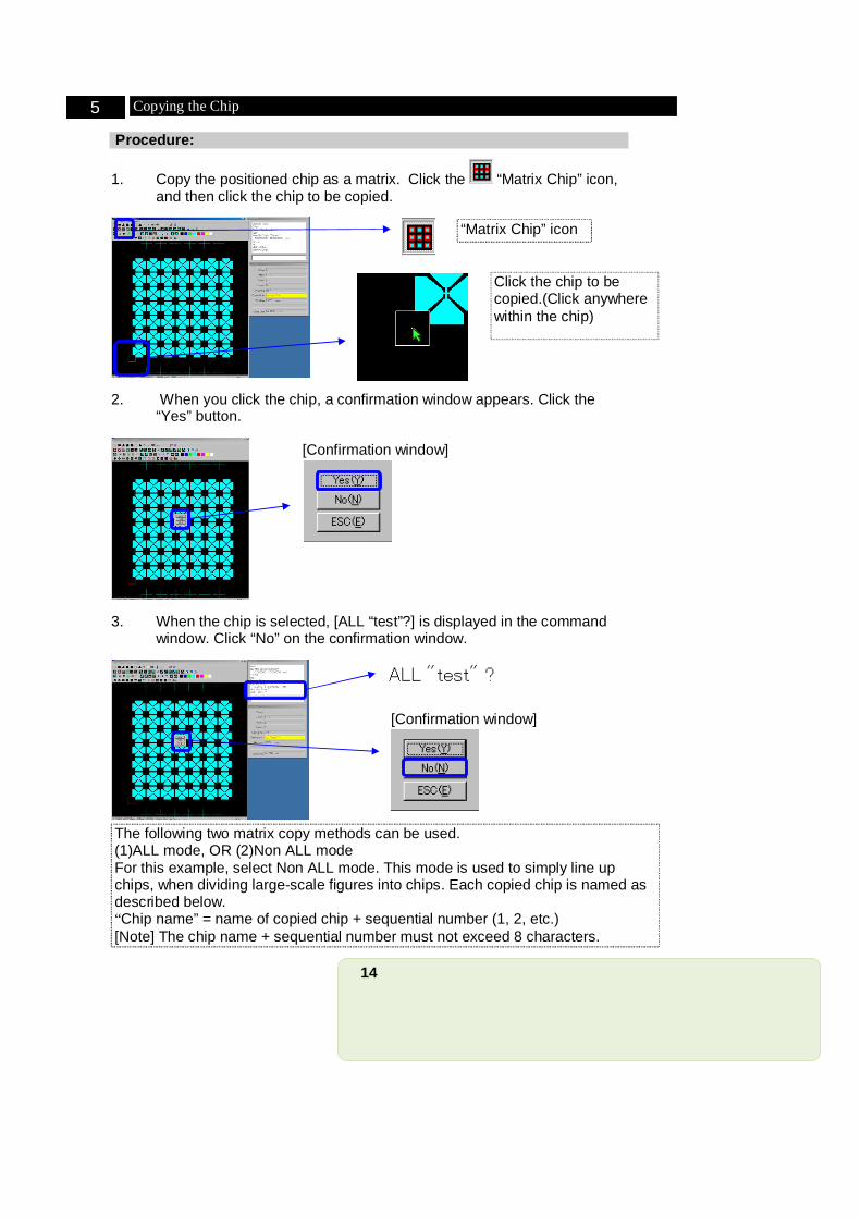
1. Copy the positioned chip as a matrix. Click the “Matrix Chip” icon, and then click the chip to be copied.
2. When you click the chip, a confirmation window appears. Click the “Yes” button.
3. When the chip is selected, [ALL “test”?] is displayed in the command window. Click “No” on the confirmation window.
5 Copying the Chip
“Matrix Chip” icon
The following two matrix copy methods can be used. (1)ALL mode, OR (2)Non ALL mode For this example, select Non ALL mode. This mode is used to simply line up chips, when dividing large-scale figures into chips. Each copied chip is named as described below. “Chip name” = name of copied chip + sequential number (1, 2, etc.) [Note] The chip name + sequential number must not exceed 8 characters.
[Confirmation window]
Click the chip to be copied.(Click anywhere within the chip)
[Confirmation window]
15
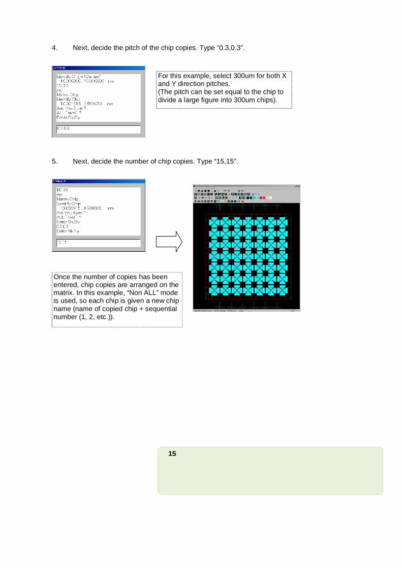
4. Next, decide the pitch of the chip copies. Type “0.3,0.3”.
5. Next, decide the number of chip copies. Type “15,15”.
For this example, select 300um for both X and Y direction pitches. (The pitch can be set equal to the chip to divide a large figure into 300um chips).
Once the number of copies has been entered, chip copies are arranged on the matrix. In this example, “Non ALL” mode is used, so each chip is given a new chip name (name of copied chip + sequential number (1, 2, etc.)).
16
Procedure:
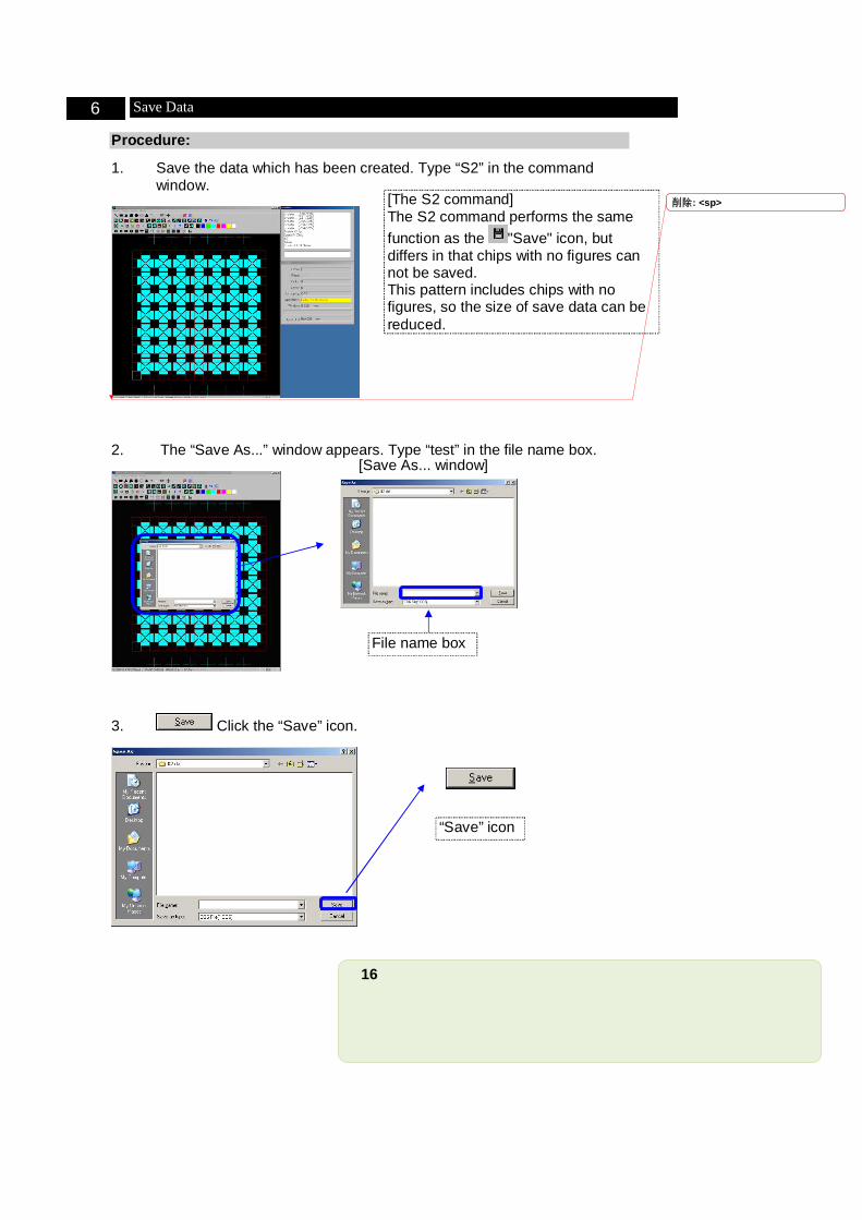
1. Save the data which has been created. Type “S2” in the command window.
2. The “Save As...” window appears. Type “test” in the file name box.
3. Click the “Save” icon.
6 Save Data
[The S2 command] The S2 command performs the same function as the "Save" icon, but differs in that chips with no figures can not be saved. This pattern includes chips with no figures, so the size of save data can be reduced.
“Save” icon
File name box
[Save As... window]
削除: <sp>
17
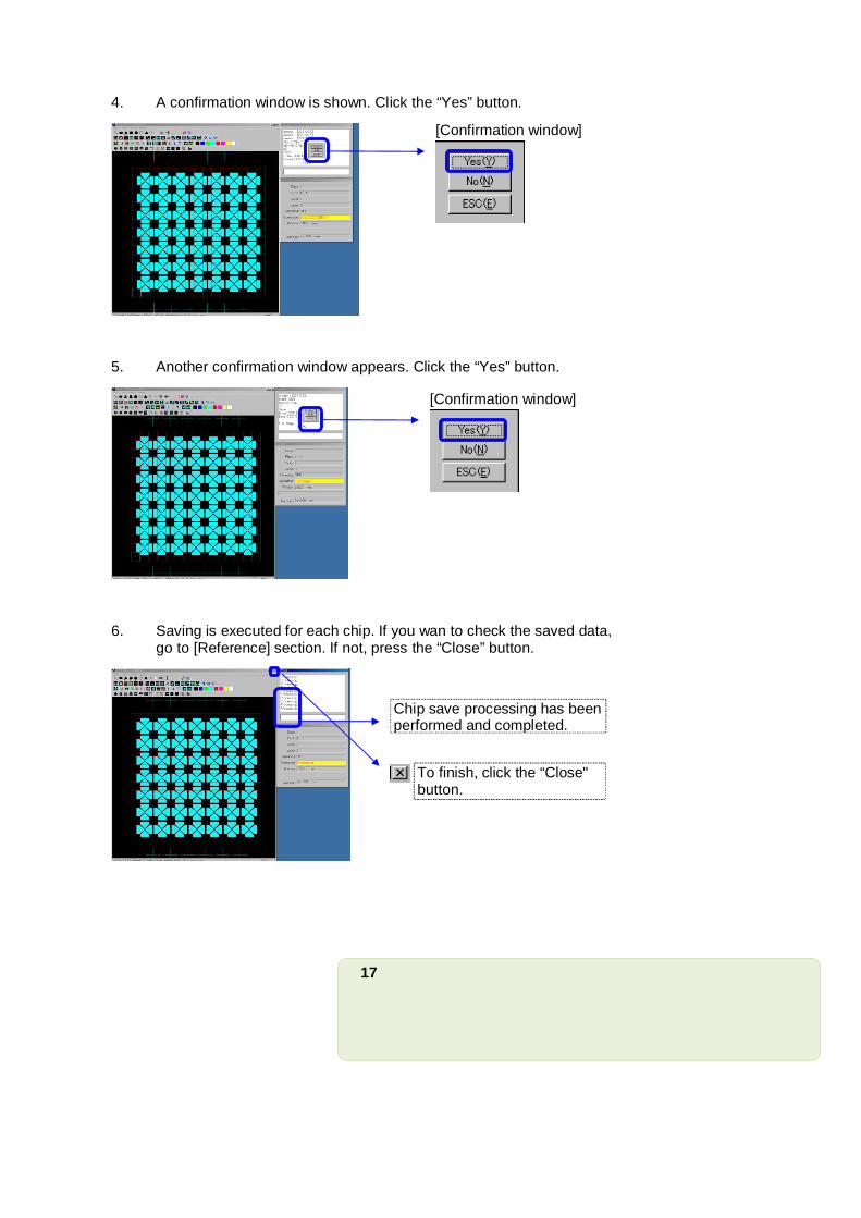
4. A confirmation window is shown. Click the “Yes” button.
5. Another confirmation window appears. Click the “Yes” button.
6. Saving is executed for each chip. If you wan to check the saved data, go to [Reference] section. If not, press the “Close” button.
Chip save processing has been performed and completed.
[Confirmation window]
[Confirmation window]
To finish, click the “Close" button.
18
Procedure:
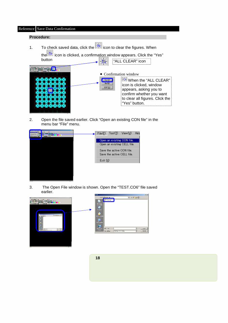
1. To check saved data, click the icon to clear the figures. When
the icon is clicked, a confirmation window appears. Click the “Yes” button
2. Open the file saved earlier. Click “Open an existing CON file” in the menu bar “File” menu.
3. The Open File window is shown. Open the “TEST.CO6” file saved earlier.
Reference Save Data Confirmation
When the “ALL CLEAR” icon is clicked, window appears, asking you to confirm whether you want to clear all figures. Click the “Yes” button.
●Confirmation window
“ALL CLEAR” icon
19
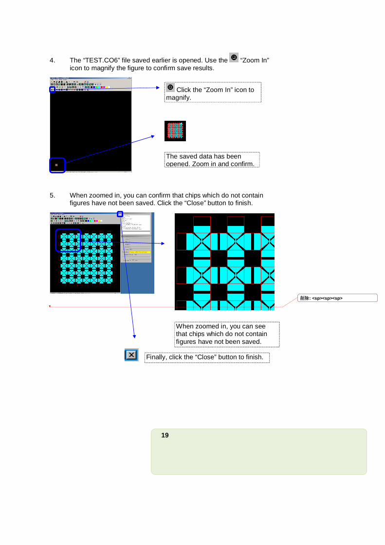
4. The “TEST.CO6” file saved earlier is opened. Use the “Zoom In” icon to magnify the figure to confirm save results.
5. When zoomed in, you can confirm that chips which do not contain figures have not been saved. Click the “Close” button to finish.
The saved data has been opened. Zoom in and confirm.
Click the “Zoom In” icon to magnify.
Finally, click the “Close” button to finish.
When zoomed in, you can see that chips which do not contain figures have not been saved.
削除: <sp><sp><sp>


![ECA [UandiStar.org]](https://img.pdfslide.us/doc/110x75/55cf9008550346703ba28dee/eca-uandistarorg.jpg)