Embed Size (px)
Citation preview
RESEARCH PAPERCAA -RP -87-4
qt J
AN ALGORITHM FOR CALCULATING_• THE AREA OF OVERLAP OF AN
ELLIPSE AND A CONVEX POLYGON
NOVEMBER 1987
gZAELECTE•
SSEP 3 0 19880
PREPARED BYDR. ROBERT L. HELMBOLD
US ARMY CONCEPTS ANALYSIS AGENCY8120 WOODMONT AVENUE
BETHESDA, MARYLAND 20814-2797
88 9 29 078
DISCLAIMER
The findings of this report are not to be construed as anofficial Department of the Army position, policy, or decision
unless so designated by other official documentation.Comments or suggestions should be addressed to:
DirectorUS Army Concepts Analysis AgencyATTN: CSCA-MV8120 Woodmont AvenueBethesda, MD 20814-2797
wit
-p.'
'pI
CAA-RP-87-4
UNCLASSIFIEDSECURITY CLASSIFICATION OF THIS PAGE
REPORT DOCUMENTATION PAGE OM or 0704r0188
Ia. REPORT SECURITY CLASSIFICATIONi lb RESTRICTIVE MARKINGSUnclassified None
2a. SECURITY CLASSIFICATION AUTHORITY 3 DISTRIBUTION/AVAILABILITY OF REPORT___________________________________ Approved for public release; distribution
2b OECLASSIFICATIONIDOWINGRADING SCHEDULE unlimited.
4 PERFORMING ORGANIZATION REPORT NUMBER(S) 5 MONITORING ORGANIZATION REPORT NUMBER (S)
CAA-RP -87-4 N/A6a NAME OF PERFORMING ORGANIZATION 5b. OFFCE SYMBOL 7a NAME OF MONi TORINC ORQANIZAriON
US Army Concepts Analysis I(if applica bleIAgency ICSCA-MVM
6c. ADDRESS (City, State, and ZIP Code) 7b ADDRESS (City, State, and ZIP Code)8120 Woodrnont AvenueBethesda, MD 20814-2797
Ba AEOF FUNOINGiS'ONSORING 8b OFFICE SYMBOL 9 PROCUREMENT INSTRUMENT IDENTIFCATION NUMBERORGANIZATION I (ifapplicable)
U..Army Concepts Analysis Agency CSCA-MVMBc ADDRESS (City. State, and ZIP Code) 10 SOURCE OF FUNDING NUMBERS
* 8120 Woodmont AvenuePROGRAM PROJECT TASK WORK uN'rBethesda, MD 203i4-2?97 ELEMENTN NO I N NO, ACCE'SS.ON %C
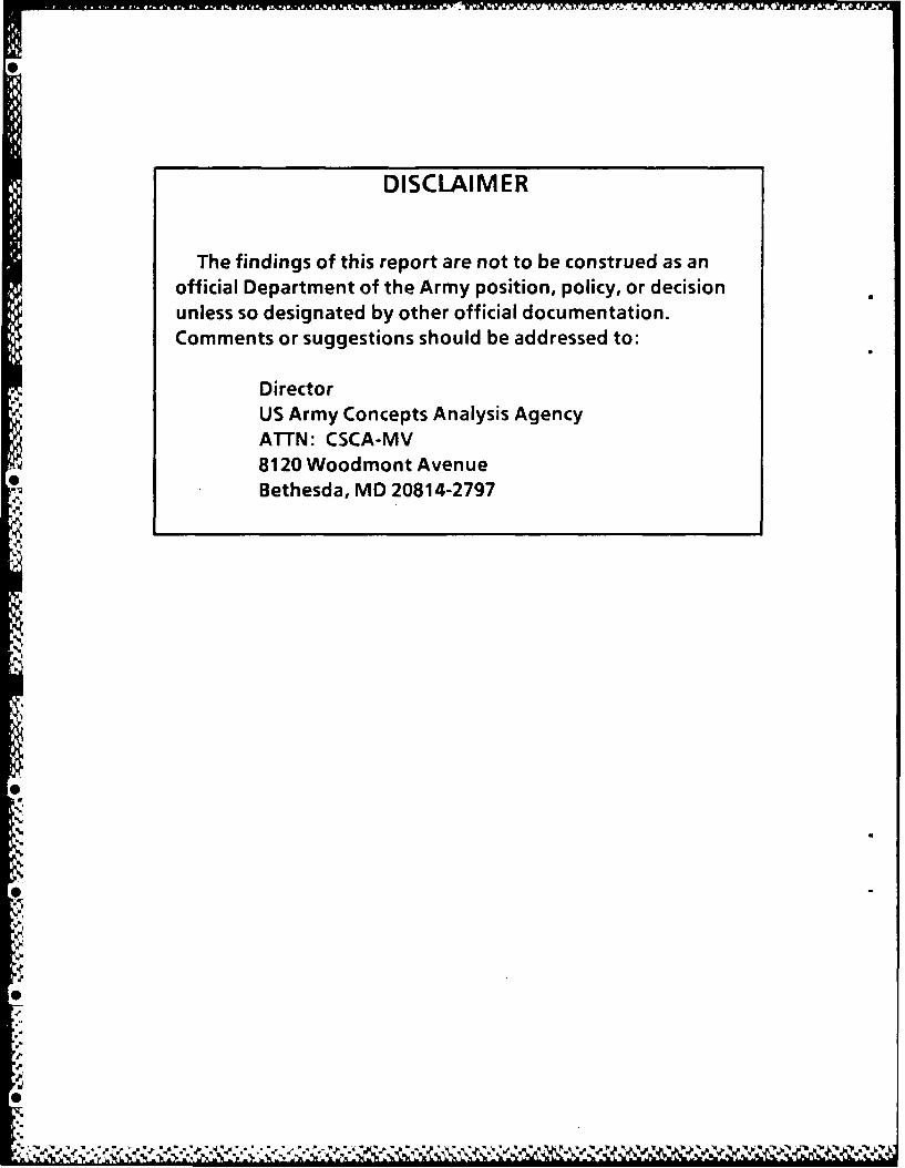
I1I TITLE (include Security Classification)An Algorithm for Calculating the Area of Overlap of an Ellipse and a Convex Polygon
12 PERSONAL AUTHOR(S)HIembold, Or. Robert L.
1 3a TYPE OF REPORT 1 3b. TIME COVERED 14 DATE OF REPORT (Year. Month, Day) 15 PAGE COUNTResearch Paper FROM 10/8TO 1187 1987 November
16G SUPPLEMENTARY NOTATION
17 COSATI CODES 18B. SUBJECT TERMS (Continue on reverse of necessary and identify by block number)Military Operations Research, Nuclear Weapons( FIED GROP SUBGROUP Simulations, Wargaming, Combat Simulation, I.
19 ABSTRACT (Continue on reverse if necessary and identify by block number)This paper describes a new an'd improved algorithm for estimating in computer simulations thearea of overlap of an ellipse and a convex polygon. The need for such algorithms arises
* frequently in military operations analysis, in particular in estimating the portion of arectangular target overlapped by a disk-shaped nuclear coverage area. A detailed,description of the algorithm and illustrations of its application are included.
20 oisTRIBUTIONAi/AILAB1IiTYOF ABSTRAC.T 12T ABSTRACT SECURITY CLASSIFICATION* INUNCL.ASIFIEDUNLIMITEO Q SAME ASRPT C] DTIC USERS Unclassified
L22a NAME OF RESPONSIBLE INDIVIDUAL 22b TELEPHflNE (include Area Code) I 2c OFFICE SYMBOL*Dr. Helmbold (202) 295-52261 CSCA-MVM
D O Farm 1473, JUN 86 Previous editions are obsolete SECURITY CLASSiFICATION OF I-iIS PAGE
UNCLASSIFIED
6K
RESEARCH PAPERCAA-RP-87-4
AN ALGORITHM FOR CALCULATING THE AREA OF OVERLAP OF ANELLIPSE AND A CONVEX POLYGON
November 1987
Prepared by
Dr. Robert L. HeImbold
US Army Concepts Analysis Agency8120 Woodmont Avenue
Bethesda, Maryland 20814-2797
"*• q " ",w" V • V "W• " • • " • • " "" d " - • • "• d '• ,', " ' '' ' •' ' ' w ' ' ""• ,• ', 4 m ', • "W
CAA-RP-87-4
PREFACE
This research paper presents an efficient new algorithm for computing theexact area of overlap of an ellipse and a convex polygon. Its fundamentalidea originated with Dr. Dennis F. DeRiggi of the US Army Concepts AnalysisAgency (CAA), who used it to develop an algorithm for computing the exactarea of overlap of a disk and a rectangle. Dr. Robert L. Heimbold, also ofCAA, subsequently observed that DeRiggi's approach generalized in an obviousway to ellipses and convex polygons.
The problem of finding the area of overlap of two generic figures ofprescribed shapes, sizes, orientations, and locations arises frequently inmilitary operations research. Damage functions are often modeled as circular"cookie-cutters," and targets are frequently represented as disks orrectangles. Convenient formulas or algorithms are available for calculatingexactly the area of overlap of two disks, or of two rectangles oriented sothat their sides are parallel. They appear to be widely known and are oftenused by the military OR community.
In addition, several methods for numerically approximating the area ofoverlap of a disk and a rectangle are available and widely used. However,they can be wildly- inaccurate for certain configurations of the disk andrectangle, none generalize easily to the case of an ellipse and convexpolygon, and they can be impractically slow and expensive when very highaccuracy is required. Hence, an efficient algorithm for calculating theexact area of overlap of an ellipse and a convex polygon would be useful inmany military OR simulations and analyses.
Such an algorithm is described in this research paper.
CAA-RP-87-4
DEPARTMENT OF THE ARMYUS ARMY CONCEPTS ANALYSIS AGENCY
I120 WOODMONT AVENUE
BETHESDA, MARYLAND 20814-2797
REPLY TO
ATTENTION OF
CSCA-MVM I 4 SEp 1998
MEMORANDUM FOR: Deputy Under Secretary of the Army (Operations Research),The Pentagon, Room 2E660, Washington, D.C. 20310
SUBJECT: An Algorithm for Calculating the Area of Overlap of an Ellipse anda Convex Polygon
1. This Research Paper grew out of an earlier effort begun by Dr. Helmboldto find an improved algorithm for approximating the area of overlap of a diskand a rectangle. This paper stimulated Dr. DeRiggi to devise a greatlyimproved and very ingenious simple exact method for computing those kinds ofoverlap areas. When this method was communicated to Dr. Helmbold, he quicklysaw that easy generalizations of Dr. DeRiggi's basic idea would yield anexcellent algorithm for calculating the area of overlap of an ellipse and apolygon.
2. This algorithm will help to increase the accuracy and efficiency of DODmilitary operations analyses, for they frequently encounter the problem ofcalculating such overlap areas. For example, ellipses are often used torepresent the area of effect of a weapon and a polygon is used to approximatethe target's configuration. Questions or inquiries should be directed to ourOffice of Special Assistant for Model Validation, U.S. Army Concepts AnalysisAgency (CSCA-MVM), 8120 Woodmont Avenue, Bethesda, MD 20814-2797,(301) 295-1669.
Encl E. B. VANDIVER IIIDirector
IL
iii
AN ALGORITHM FOR CALCULATING STUDYTHE AREA OF OVERLAP OF AN SUMMARY"CSAAt* ELLIPSE AND A CONVEX POLYGON CAA-RP-87-4
THE REASON FOR PERFORMING THIS STUDY was to develop and document animproved algorithm for determining in computer simulations the area ofoverlap of an ellipse and a convex polygon.
THE PRINCIPAL FINDINGS are that a useful algorithm can be developed fordetermining in computer simulations the area of overlap of an ellipse and aconvex polygon. It appears to be a new method offering many advantages overthose previously proposed.
THE MAIN ASSUMPTION is that the polygon is convex.
THE PRINCIPAL LIMITATION is that numerical roundoff error may, under someconditions, reduce the accuracy of the result.
THE SCOPE OFTHE WORK is limited to determining the area of overlap of anellipse and a convex polygon.
THE RESEARCH OBJECTIVE was to develop and document an algorithm fordetermining in computer simulations the area of overlap of an ellipse and aconvex polygon.
THE WORK WAS SUPPORTED BY the US Army Concepts Analysis Agency.
Tear-out copies of this synopsis are at back cover.
V
CAA-RP-87-4
CONTENTS
CHAPTER Page
1 EXECUTIVE SUMMARY...................................... 1-1
Problem................................................ 1-1Background............................................. 1-1Scope.................................................. 1-4Limitations............................................ 1-4Tirneframe.............................................. 1-4Key Assumptions........................................ 1-4Approach............................................... 1-4Conclusions............................................ 1-7Observations........................................... 1-7
2 APPROACH............................................... 2-1
Introduction........................................... 2-1Describe the Configurations of the Polygon and
*Ellipse.............................................. 2-2Reduce to Disk-Polygon Overlap Situation ................. 2-2Reduce Disk-Polygon Overlap to a Sequence ofDisk-Wedge Overlaps................................... 2-3
23 RESULTS................................................ 3-1
Introduction........................................... 3-1Example 1.............................................. 3-1Example 2.............................................. 3-2Example 3.............................................. 3-3Example 4.............................................. 3-4Example 5.............................................. 3-5
4 CONCLUSIONS AND OBSERVATIONS............................ 4-1
Results................................................ 4-1Observations........................................... 4-1
APPENDIX
A Mathematical Development................................ A-1B Computer Programs...................................... B-1C Distribution........................................... c-i
GLOSSARY...................................................... Glossary-i
STUDY SUMMARY (tear-out copies)
*v vii
CAA-RP-87-4
FIGURES
FIGURES Page
i-i Area of Overlap ...................................... i-i1-2 Replace Rectangle with a Regular Array of Points ..... 1-3
1-3 Replace Disk with a Family of Rectangles ............. 1-4i-4a Convex Polygon with Vertices Numbered in Positive
Order ............................................... 1-51-4b Construction Lines ................................... 1-6
2-1 Ellipse and Polygon in General Configuration ......... 2-12-2 Disk-Polygon Overlap Configuration Obtained by Applying
Affine Transformation to Figure 2-1 ................ 2-3
3-i Configuration for Example 2 .......................... 3-23-2 Configuration for Example 3 .......................... 3-33-3 Configuration For Example 4 .......................... 3-43-4 Configuration for Example 5 .......................... 3-6
A-i Different Disk-Wedge Overlay Cases Possible .......... A-3A-2 Case 3--Disk Covers the Vertex of Wedge .............. A-5A-3 Overlap of Two Rectangles ............................ A-7A-4 Overlap of Two Line Segments .......................... A-8A-5 Two UlsKs in General Configuration ................... A-1OA-6 Two Disks in Standard Configuration .................. A-ilA-7 Labeled for the Overlap of Two Disks ................. A-12
TABLES
TABLE
3-1 Values for the Configuration for Example I(Figure 2-1) ...................................... 3-1
3-2 Values for the Configuration of Example 2(Figure 3-1) ...................................... 3-2
3-3 Values for the Configuration of Example 3(Figure 3-2) ...................................... 3-3
3-4 Values for the Configuration of Example 4(Figure 3-3) ...................................... 3-5
3-5 Values for the Configuration of Example 5(Figure 3-4) ...................................... 3-7
3-6 Results of Method I for Example 5 ................... 3-73-7 Results of Method 2 for Example 5 ................... 3-8
viii
'Ik
CAA-RP-87-4
CHAPTER I
EXECUTIVE SUMMARY
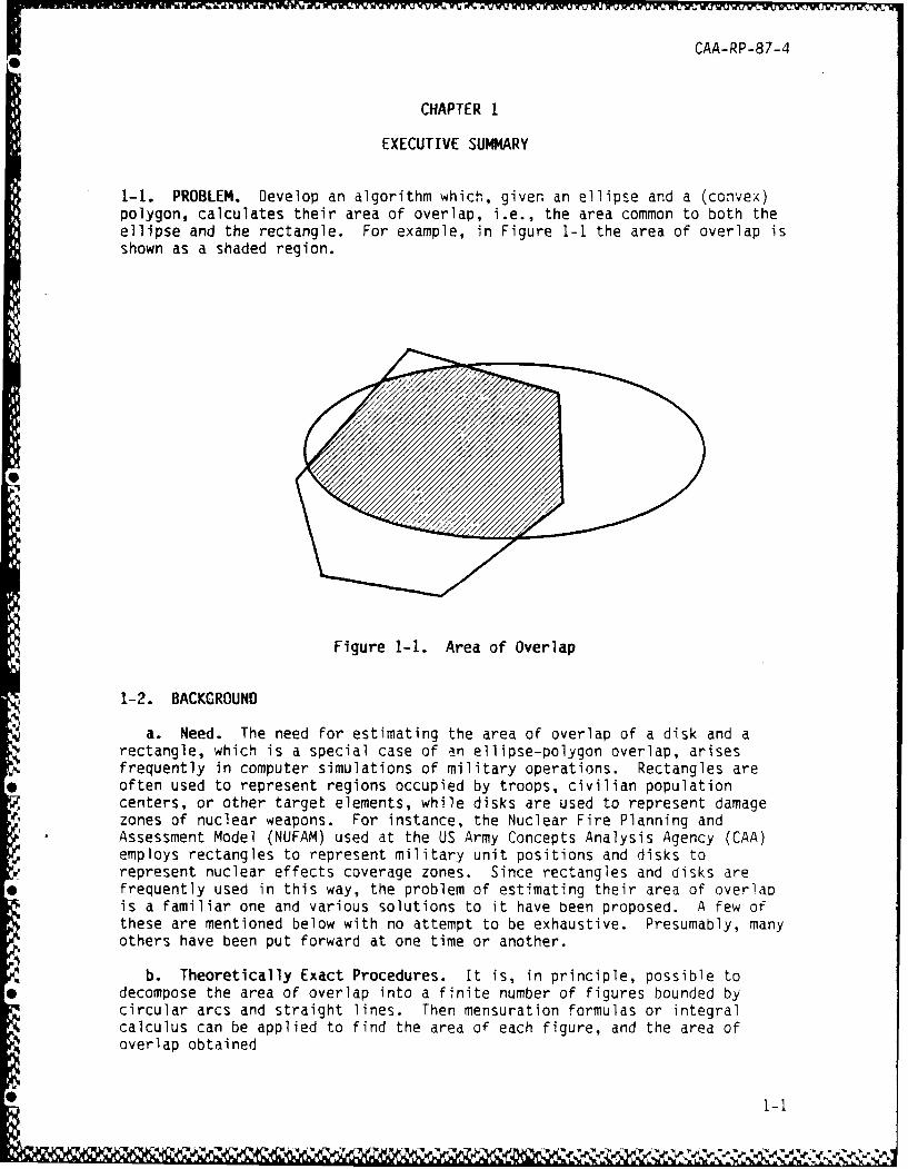
1-1. PROBLEM. Develop an algorithm which, given an ellipse and a (convex)polygon, calculates their area of overlap, i.e., the area common to both theellipse and the rectangle. For example, in Figure 1-1 the area of overlap isshown as a shaded region.
Figure 1-i. Area of Overlap
1-2. BACKGROUND
a. Need. The need for estimating the area of overlap of a disk and arectangle, which is a special case of an ellipse-polygon overlap, arisesfrequently in computer simulations of military operations. Rectangles areoften used to represent regions occupied by troops, civilian populationcenters, or other target elements, while disks are used to represent damagezones of nuclear weapons. For instance, the Nuclear Fire Planning andAssessment Model (NUFAM) used at the US Army Concepts Analysis Agency (CAA)employs rectangles to represent military unit positions and disks torepresent nuclear effects coverage zones. Since rectangles and disks arefrequently used in this way, the problem of estimating their area of overlapis a familiar one and various solutions to it have been proposed. A few ofthese are mentioned below with no attempt to be exhaustive. Presumably, manyothers have been put forward at one time or another.
b. Theoretically Exact Procedures. It is, in principle, possible todecompose the area of overlap into a finite number of figures bounded bycircular arcs and straight lines. Then mensuration formulas or integralcalculus can be applied to find the area of each figure, and the area ofoverlap obtained
0 IleN
CAA-RP-87-4
as their sum. This method provides theoretically exact results, since nonumerical approximations other than those involved in finite arithmetic pre-cision are required. However, attempts to program this approach on computershave shown it to be extremely cumbersome. The practical difficulty is that alarge number of special cases must be considered, depending on how the diskintercepts the rectangle. Hence the algorithm must be arranged to determinewhich of the special cases applies, to subdivide the area of overlap appro-priately, and to apply the correct mensuration formula to each subdivision.This proves exceedingly tedious to implement. Moreover, this approach doesnot generalize readily to the overlaps of polygons with either disks orellipses.
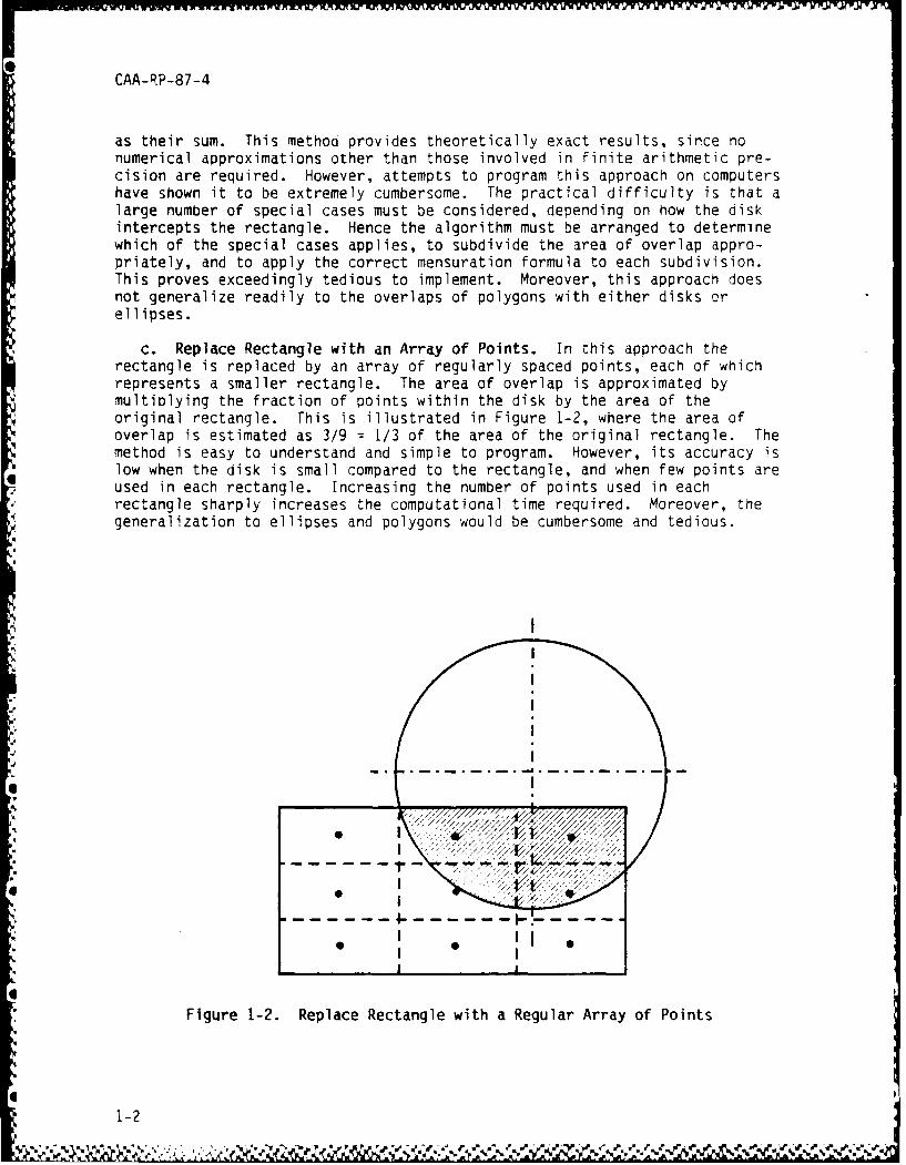
c. Replace Rectangle with an Array of Points. In this approach therectangle is replaced by an array of regularly spaced points, each of whichrepresents a smaller rectangle. The area of overlap is approximated bymultiplying the fraction of points within the disk by the area of theoriginal rectangle. This is illustrated in Figure 1-2, where the area ofoverlap is estimated as 3/9 = 1/3 of the area of the original rectangle. Themethod is easy to understand and simple to program. However, its accuracy islow when the disk is small compared to the rectangle, and when few points areused in each rectangle. Increasing the number of points used in eachrectangle sharply increases the computational time required. Moreover, thegeneralization to ellipses and polygons would be cumbersome and tedious.
II
I
Figure 1-2. Replace Rectangle with a Regular Array of Points
1-2
'4.
CAA-RP-87-4
d. Random Points in Rectangle. Here a certain number of points in therectangle are selected randomly, and the area of overlap estimated as thefraction of them inside the disk. This Monte Carlo approximation to the areaof overlap has all the usual advantages and disadvantages of that method. Inparticular, many points are needed if the result is to be numericallyaccurate and statistically reliable. Moreover, the generalization toellipses and polygons is not evident.
e. Functional Approximation. This approach begins by considering thecharacteristic functions of the rectangle and the disk, where the charac-teristic function of any region is defined to be equal to one for points inthe region, and zero elsewhere. Then the area of overlap of any two regionsis just the integral of the product of their characteristic functions. Sincethe product of the characteristic functions vanishes outside the area ofoverlap, the integral may be carried out over all space, ard that is at leasta useful theoretical simplification. In the functional approximation method,the (discontinuous) characteristic functions of the rectangle and disk areapproximated by continuous functions. The functions used can be polynomials,Fourier series, orthogonal series of various types, and so forth. One diffi-culty with this approach is that it often is hard to estimate the accuracy ofthe result. Another is that several terms must be carried in the functionalapproximation. Moreover, a familiarity with advanced mathematical methods isneeded to understand the method and to implement it properly. Finally, thegeneralization to ellipses and polygons would add measurably to thecomplexity of this approach.
f. Curve Fitting. Here a number of trial cases are accurately computed,and the results are tabulated against such key parameters of the situation asthe rectangular dimensions of the rectangle, the offset of the disk's centerfrom the center of the rectangle, and radius of the disk. (Usually these arenormalized to some standard dimension, such as the disk's radius.) A more orless arbitrary function is then fitted to the tabulated values, and used toestimate the area of overlap for other values of the key variables. This issimple in conception. However, it is not easy to determine whether thefunctional form used for the fitting process gives satisfactorily accuratevalues for situations different from those used to obtain the tabulatedvalues. Moreover, it depends on having a number of cases for which the areaof overlap is accurately known, and so to that extent assumes what is to befound. Finally, curves fitted to the disk-rectangle case have no applicationto the general ellipse-polygon case.
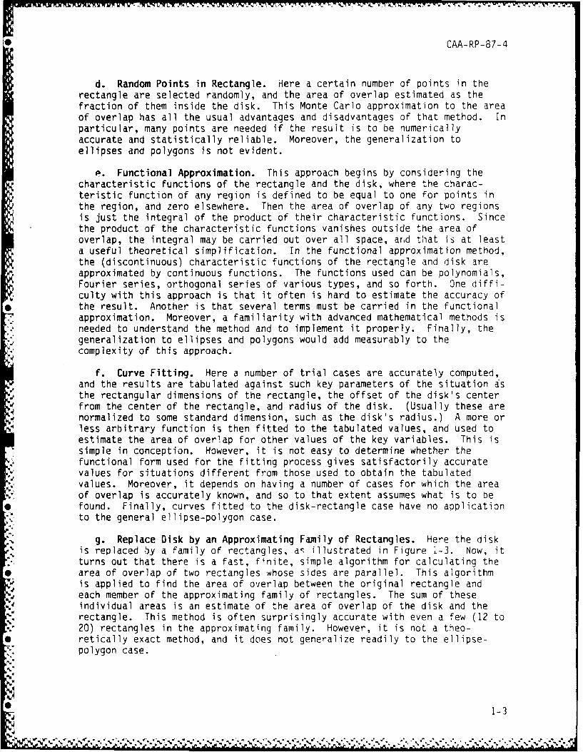
g. Replace Disk by an Approximating Family of Rectangles. Here the diskis replaced by a family of rectangles, as illustrated in Figure 1-3. Now, itturns out that there is a fast, finite, simple algorithm for calculating thearea of overlap of two rectangles whose sides are parallel. This algorithmis applied to find the area of overlap between the original rectangle andeach member of the approximating family of rectangles. The sum of theseindividual areas is an estimate of the area of overlap of the disk and therectangle. This method is often surprisingly accurate with even a few (12 to20) rectangles in the approximating family. However, it is not a theo-retically exact method, and it does not generalize readily to the ellipse-polygon case.
0 1-3
CAA-RP-87-4
Sf I l
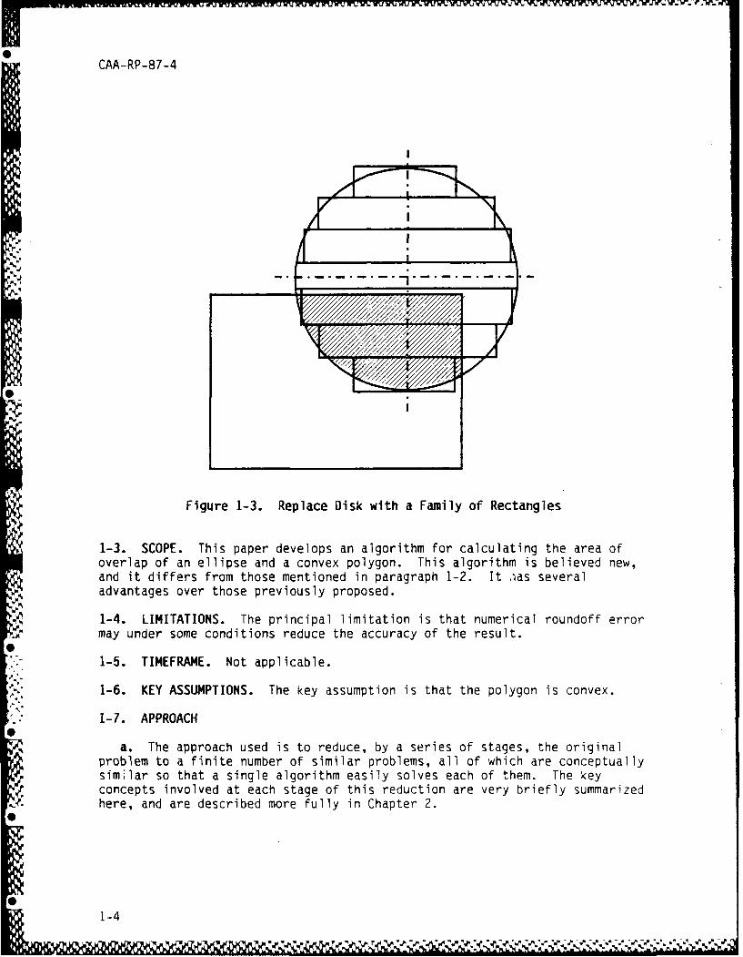
Figure 1-3. Replace Disk with a Family of Rectangles
1-3. SCOPE. This paper develops an algorithm for calculating the area ofoverlap of an ellipse and a convex polygon. This algorithm is believed new,and it differs from those mentioned in paragraph 1-2. It -as severaladvantages over those previously proposed.
1-4. LIMITATIONS. The principal limitation is that numerical roundoff errormay under some conditions reduce the accuracy of the result.
1-5. TIMEFRAME. Not applicable.
1-6. KEY ASSUMPTIONS. The key assumption is that the polygon is convex.
1-7. APPROACH
a. The approach used is to reduce, by a series of stages, the originalproblem to a finite number of similar problems, all of which are conceptuallysimilar so that a single algorithm easily solves each of them. The keyconcepts involved at each stage of this reduction are very briefly summarizedhere, and are described more fully in Chapter 2.
1-4
CAA-RP-87-4
b. First, any ellipse-polygon overlap case can be reduced to anequivalent disk-polygon overlap situation by an affine transformation ofcoordinates that shrinks the major axis of the ellipse until its equal to theminor axis. Such a transformation clearly maps the original convex polygononto some other, but also convex, polygon. So the problem has now beenreduced to one of finding the area of overlap of a disk with the interior ofa convex polygon.
c. Second, observe that since the area of the disk is known, its area ofoverlap with the interior of the polygon could easily be found if we knew itsarea of overlap with the exterior. We now focus on finding the disk's areaof overlap with the exterior of the polygon.
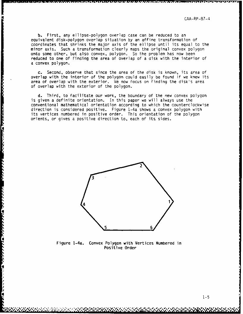
d. Third, to facilitate our work, the boundary of the new convex polygonis given a definite orientation. In this paper we will always use theconventional mathematical orientation according to which the counterclockwisedirection is considered positive. Figure 1-4a shows a convex polygon withits vertices numbered in positive order. This orientation of the polygonorients, or gives a positive direction to, each of its. sides.
I2
44
5 6
Figure 1-4a. Convex Polygon with Vertices Numbered inPositive Order
i . . . .. .. . . -5
CAA-RP-87-4
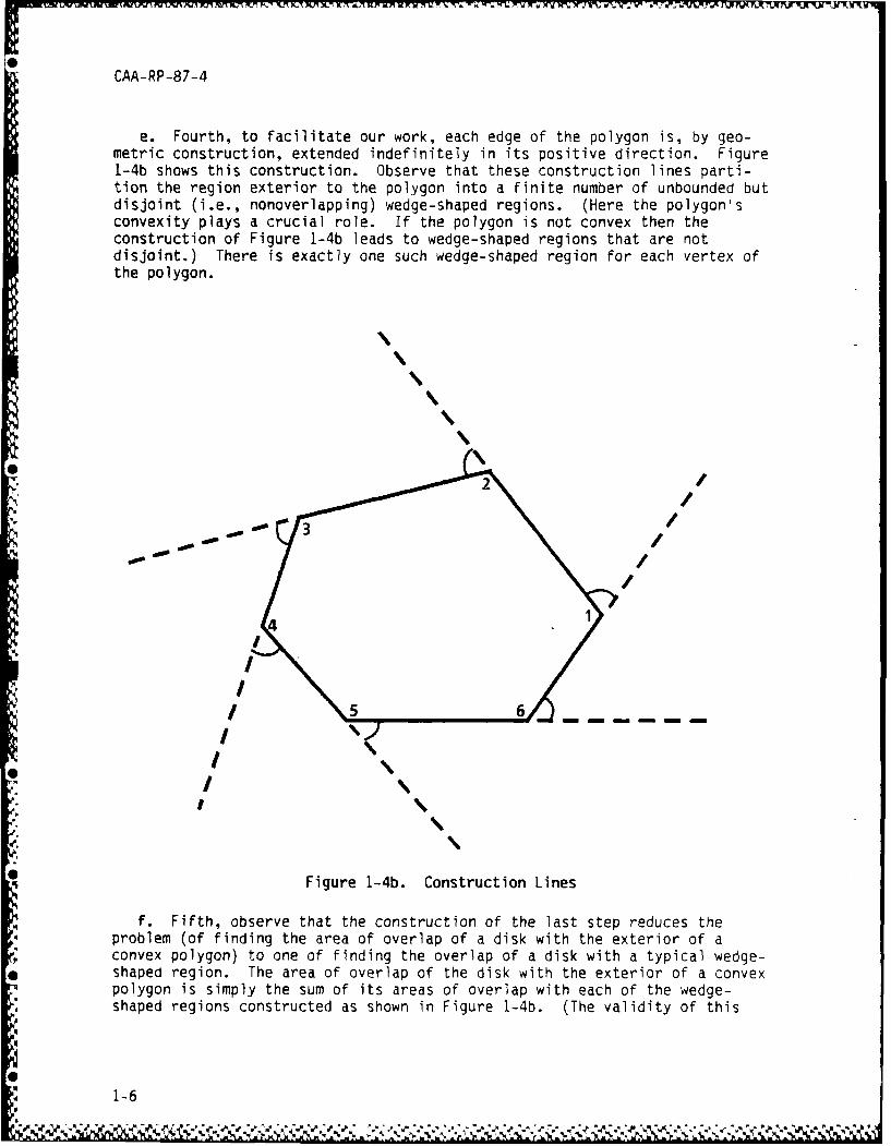
e. Fourth, to facilitate our work, each edge of the polygon is, by geo-metric construction, extended indefinitely in its positive direction. Figure1-4b shows this construction. Observe that these construction lines parti-tion the region exterior to the polygon into a finite number of unbounded butdisjoint (i.e., nonoverlapping) wedge-shaped regions. (Here the polygon'sconvexity plays a crucial role. If the polygon is not convex then theconstruction of Figure 1-4b leads to wedge-shaped regions that are notdisjoint.) There is exactly one such wedge-shaped region for each vertex ofthe polygon.
5 6
/
////
Figure 1-4b. Construction Lines
f. Fifth, observe that the construction of the last step reduces theproblem (of finding the area of overlap of a disk with the exterior of aconvex polygon) to one of finding the overlap of a disk with a typical wedge-shaped region. The area of overlap of the disk with the exterior of a convexpolygon is simply the sum of its areas of overlap with each of the wedge-shaped regions constructed as shown in Figure 1-4b. (The validity of this
1-6
CAA-RP-87-4
statement depends crucially on the disjointness of the wedge-shaped regions,and hence on the convexity of the polygon.)
g. Sixth, it happens that there is a simple, convenient, finite, theo-retically exact algorithm for calculating the area of overlap of a disk and awedge-shaped region of the sort shown in Figure 1-4b. Hence, the problem offinding the individual disk-wedge overlap areas can be considered as easilysolved. This completes our reduction of the original problem to a finitenumber of similar problems, all of which are conceptually similar, so that asingle algorithm easily solves each of them.
1-8. CONCLUSIONS. A simple finite algorithm suffices to calculate the areaof overlap of an ellipse and a polygon. The resultant algorithm is widelyapplicable in the sense that it gives theoretically exact answers for allpossible configurations of the ellipse and the polygon. It is user-friendlyin the sense that its implementation involves a straightforward computationwhose net result is easily discernable. As a result, the algorithm should beeasy to verify, debug, modify, or incorporate confidently into larger pro-grams. The accuracy of the computation can be maintained by using double-precision arithmetic to control roundoff errors.
1-9. OBSERVATIONS
a. Practical implementation of the algorithm would be aided by developingsubroutines--optimized for speed--for incorporation into large simulations orwargames such as NUFAM, CEM, FORCEM, COSAGE, VIC, and others.
b. The method yields the exact area of overlap of an ellipse with a con-vex polygon. Since a triangle is convex, the method is in principle capableof being applied to find the exact area of overlap of an ellipse with anyfinite region that can be triangulated, i.e., with any polygon. Triangu-lation is not actually necessary--any decomposition of the polygonal regioninto disjoint convex polygons is sufficient.
c. Many regions that arise in practice can be approximated satisfactorilyby polygons. Hence, the method can in principle be applied to approximatethe area of overlap of an ellipse with a fairly arbitrary region of the sortthat often arises in practice.
d. Although it may not be the most efficient algorithm for the purpose,the method can in principle be used to find the area of any convex polygon.All that is necessary is to find the area of overlap of the polygon with adisk whose radius is sufficiently large that it completely covers thepolygon. If the area of overlap does not change when the disk's radius isincreased slightly, then the radius is sufficiently large.
1-7
*$ CAA-RP-87-4
CHAPTER 2
APPROACH
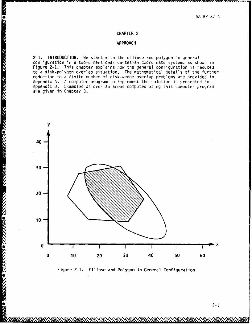
2-1. INTRODUCTION. We start with the ellipse and polygon in generalconfiguration in a two-dimensional Cartesian coordinate system, as shown inFigure 2-1. This chapter explains how the general configuration is reducedto a disk-polygon overlap situation. The mathematical details of the furtherreduction to a finite number of disk-wedge overlap problems are provided inAppendix A. A computer program to implement the solution is presented in
Appendix 8. Examples of overlap areas computed using this computer programare given in Chapter 3.
Y
40 -
30-
20-
, 10
0 10 20 30 40 50 60
Figure 2-1. Ellipse and Polygon in General Configuration
CAA-RP-87-4
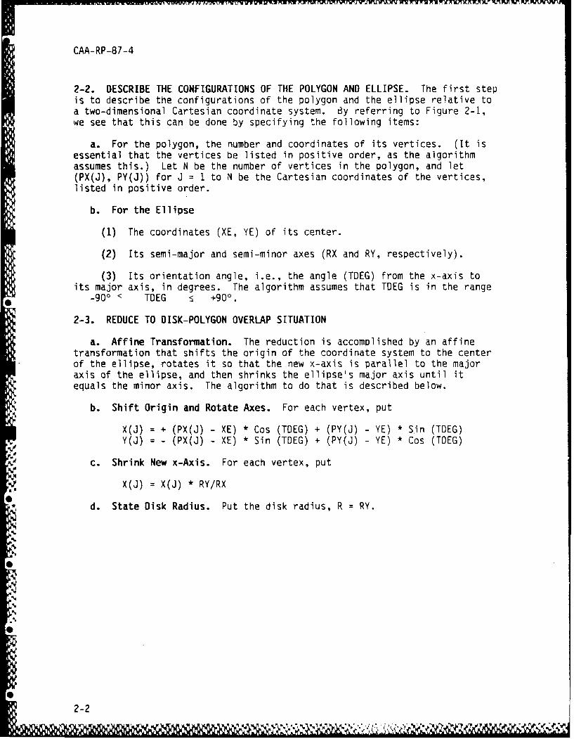
2-2. DESCRIBE THE CONFIGURATIONS OF THE POLYGON AND ELLIPSE. The first stepis to describe the configurations of the polygon and the ellipse relative toa two-dimensional Cartesian coordinate system. By referring to Figure 2-1,we see that this can be done by specifying the following items:
a. For the polygon, the number and coordinates of its vertices. (It isessential that the vertices be listed in positive order, as the algorithmassumes this.) Let N be the number of vertices in the polygon, and let(PX(J), PY(J)) for J = I to N be the Cartesian coordinates of the vertices,listed in positive order.
b. For the Ellipse
(1) The coordinates (XE, YE) of its center.
(2) Its semi-major and semi-minor axes (RX and RY, respectively).
(3) Its orientation angle, i.e., the angle (TDEG) from the x-axis toits major axis, in degrees. The algorithm assumes that TDEG is in the range
-900 < TDEG +90Q.
2-3. REDUCE TO DISK-POLYGON OVERLAP SITUATION
a. Affine Transformation. The reduction is accomplished by an affinetransformation that shifts the origin of the coordinate system to the centerof the ellipse, rotates it so that the new x-axis is parallel to the majoraxis of the ellipse, and then shrinks the ellipse's major axis until itequals the minor axis. The algorithm to do that is described below.
b. Shift Origin and Rotate Axes. For each vertex, put
X(J) = + (PX(J) - XE) * Cos (TOEG) + (PY(J) - YE) * Sin (TDEG)Y(J) = - (PX(J) - XE) * Sin (TDEG) + (PY(J) - YE) * Cos (TDEG)
c. Shrink New x-Axis. For each vertex, put
X(J) = X(J) * RY/RX
d. State Disk Radius. Put the disk radius, R RY.
2-2
CAA-RP-87-4
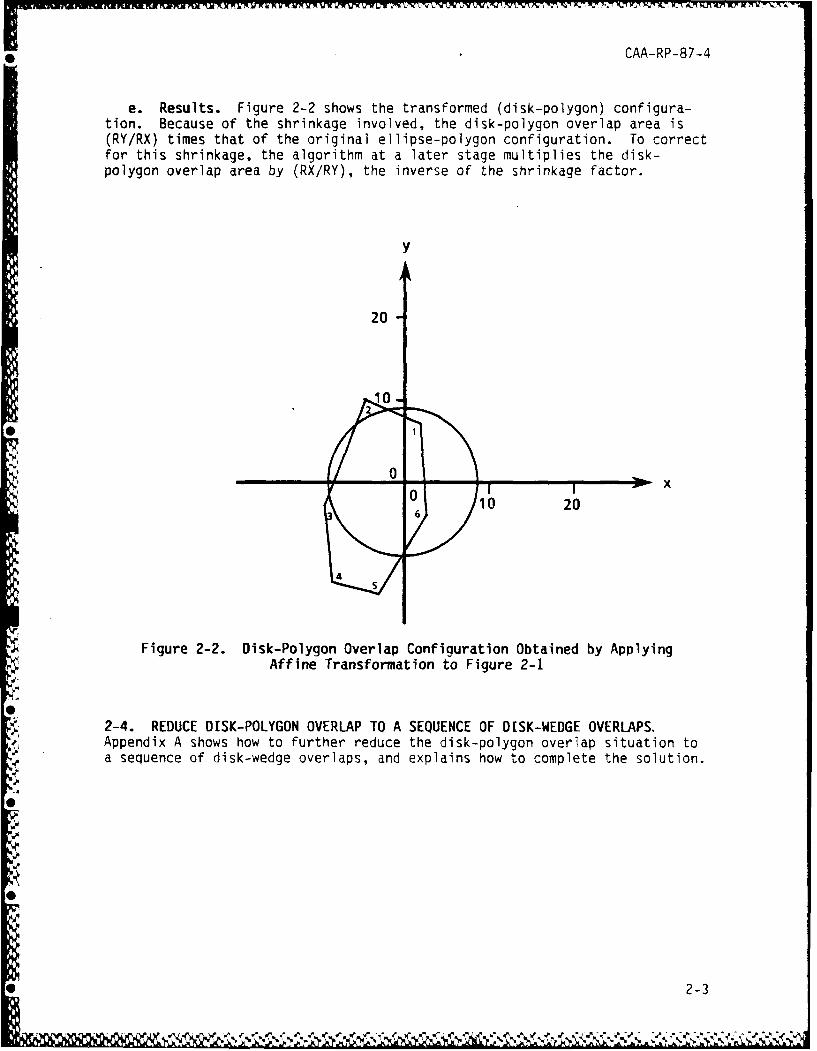
e. Results. Figure 2-2 shows the transformed (disk-polygon) configura-tion. Because of the shrinkage involved, the disk-polygon overlap area is(RY/RX) times that of the original ellipse-polygon configuration. To correctfor this shrinkage, the algorithm at a later stage multiplies the disk-polygon overlap area by (RX/RY), the inverse of the shrinkage factor.
y
20
102
r00 10 206
4
Figure 2-2. Disk-Polygon Overlap Configuration Obtained by ApplyingAffine Transformation to Figure 2-1
2-4. REDUCE DISK-POLYGON OVERLAP TO A SEQUENCE OF DISK-WEDGE OVERLAPS.Appendix A shows how to further reduce the disk-polygon overlap situation toa sequence of disk-wedge overlaps, and explains how to complete the solution.
2-3
0e CAA-RP-87-4
CHAPTER 3
RESULTS
3-i. INTRODUCTION. This chapter presents some examples of overlap areascomputed using the method expounded in this paper. In this chapter, allresults are given to six significant digits.
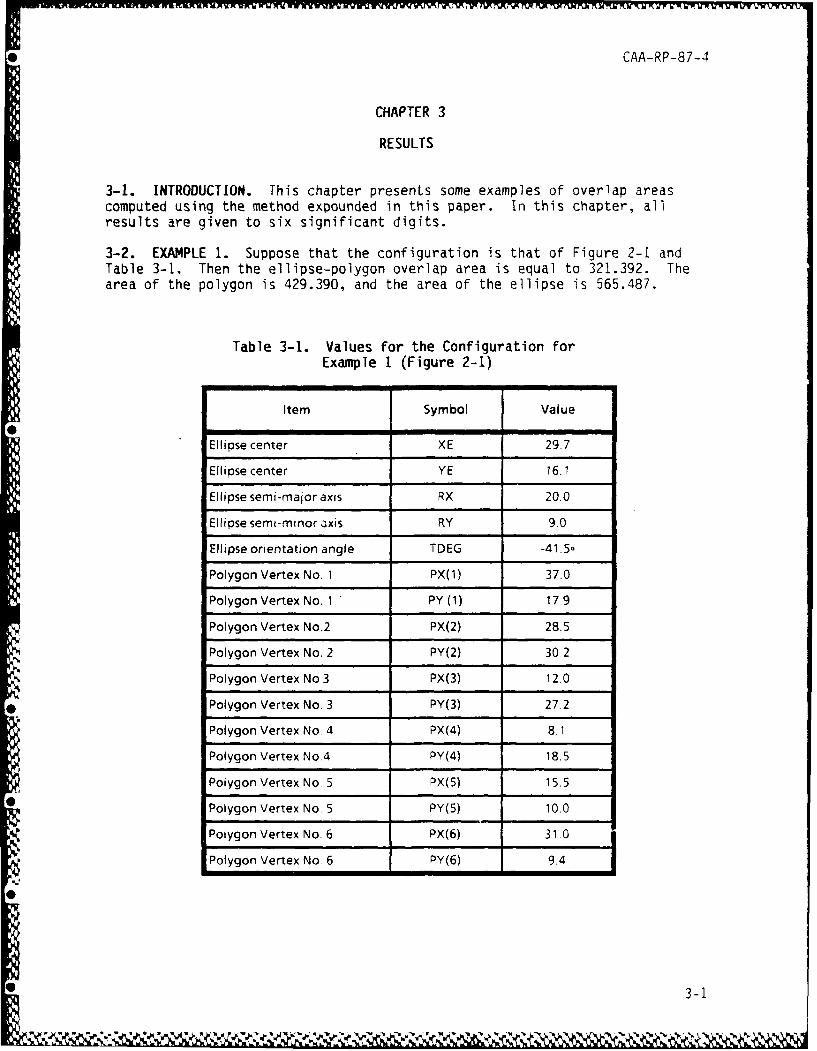
3-2. EXAMPLE 1. Suppose that the configuration is that of Figure 2-1 andTable 3-I. Then the ellipse-polygon overlap area is equal to 321.392. Thearea of the polygon is 429.390, and the area of the ellipse is 565.487.
Table 3-1. Values for the Configuration forExample 1 (Figure 2-i)
Item Symbol Value
0Ellipse center XE 2T7
Ellipse center XE 16.7
Ellipse semi-manor axis RX 20.0
Ellipse semi-minor axis RY 9.0
Ellipse orientation angle TDEG -41 .5o
Polygon Vertex No. 1 PX(1) 37.0
Polygon Vertex No. 1 PY (1) 17.9
Polygon Vertex No.2 PX(2) 28.5
Polygon Vertex No. 2 PY(2) 30.2
Polygon Vertex No 3 PX(3) 12.0
Polygon Vertex No. 3 PY(3) 27.2
Polygon Vertex No. 4 PX(4) 8. 1
Polygon Vertex No.4 PY(4) 18.5
Polygon Vertex No. 5 PX(5) 15.5
Polygon Vertex No. 5 PY(5) 10.0
Polygon Vertex No. 6 PX(6) 31 0
Polygon Vertex No. 6 PY(6) 9.4
S3-1
CAA-RP-87-4
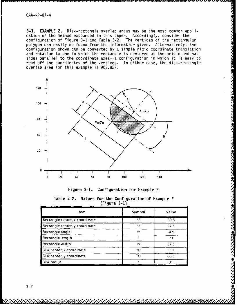
3-3. EXAMPLE 2. Disk-rectangle overlap areas may be the most common appli-cation of the method expounded in this paper. Accordingly, consider theconfiguration of Figure 3-i and Table 3-2. The vertices of the rectangularpolygon can easily be found from the informatior given. Alternatively, theconfiguration shown can be converted by a simple rigid coordinate translationand rotation to one in which the rectangle is centered at the origin and hassides parallel to the coordinate axes--a configuration in which it is easy toread off the coordinates of the vertices. In either case, the disk-rectangleoverlap area for this example is 903.827.
120
100
80
40 .
20
0-I I I I I
0 20 40 60 go 100 120 140
Figure 3-1. Configuration for Example 2
Table 3-2. Values for the Configuration of Example 2(Figure 3-1)
Item Symbol ValueRectangie center, x-coordi nate R 80.5Rectnl etr -oriae8.Rectangle center, y-coordinate YR 57_5
Rectangle angle H -42
Rectangle length 73
Rectangle width w 37 5
Disk center, x-coordinate xD 111
Disk cente;, y-coordinate YD 66 5
Disk radius r 31
3-2
CAA-RP-87-4
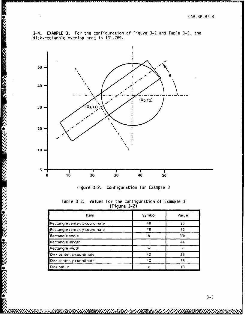
3-4. EXAMPLE 3. For the configuration of Figure 3-2 and Table 3-3, thedisk-rectangle overlap area is 131.769.
50
40
30 -
10
"0- I I.
0 10 20 30 40 50
Figure 3-2. Configuration for Example 3
Table 3-3. Values for the Configuration of Example 3(Figure 3-2) ______
10-
Item Symbol Value
Rectangle center, x-coordinate XR 25Rectangle center, y-coordinate YR 32
Rectangle angle 0 33-
Rectangle length 1 44
Rectangle width w 7
Disk center, x-coordrnate XD 36Disk center, y-coordinate xD 36
Disk radius r 10
3-3
CAA-RP-87-4
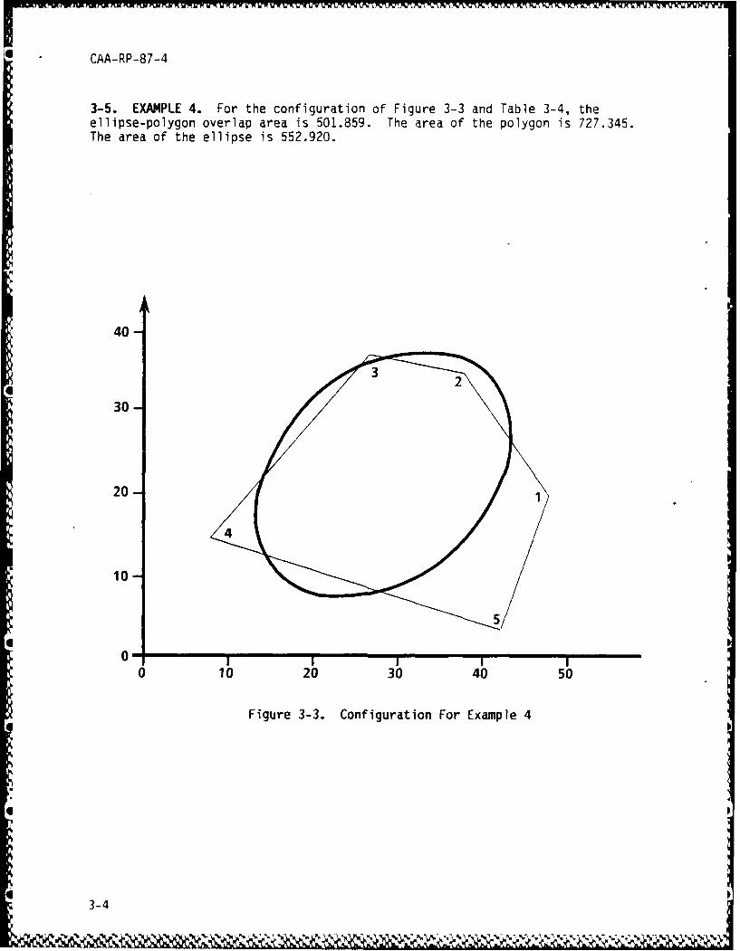
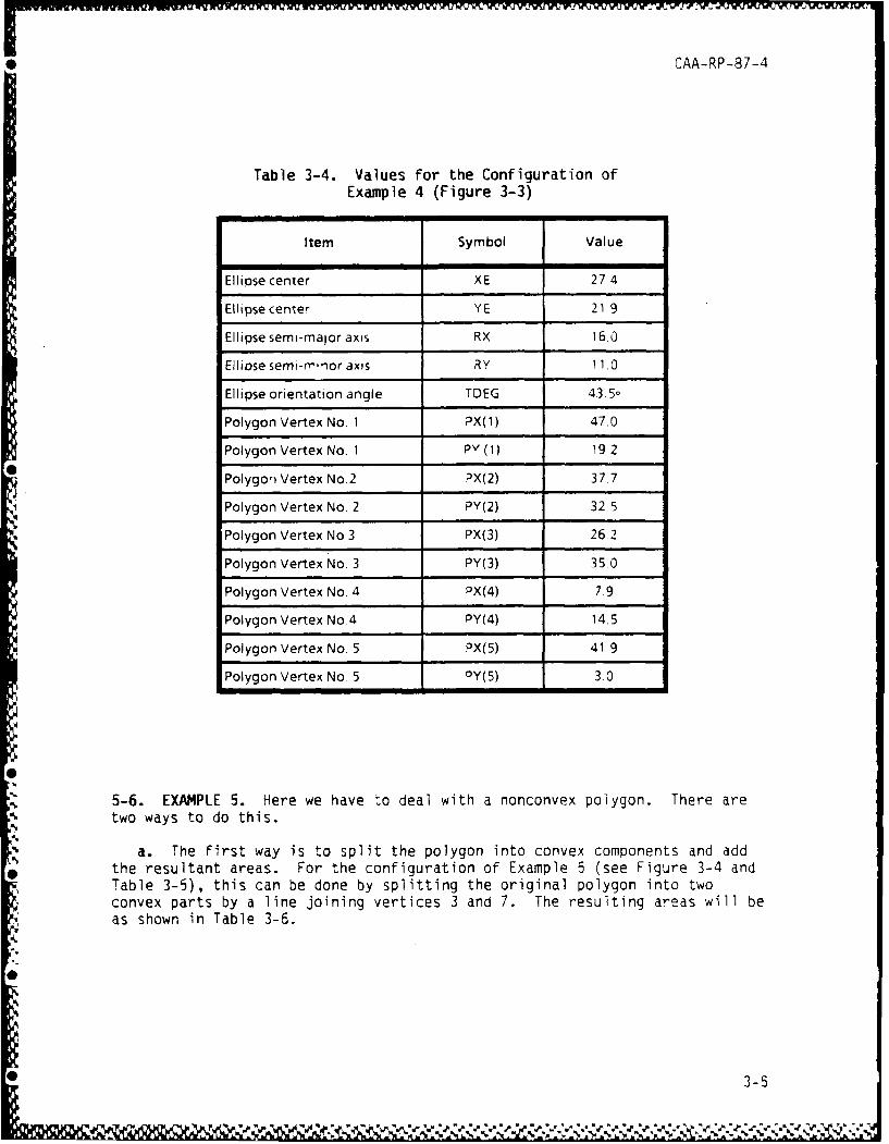
3-5. EXAMPLE 4. For the configuration of Figure 3-3 and Table 3-4, theellipse-polygon overlap area is 501.859. The area of the polygon is 727.345.The area of the ellipse is 552.920.
40-
3 0 -
20 0
10-
*5
00 10 20 30 40 50
Figure 3-3. Configuration For Example 4
3-4.. .. .. 6
CAA-RP-87-4
Table 3-4. Values for the Configuration ofExample 4 (Figure 3-3)
Item Symbol Value
Ellipse center XE 274
Ellipse center YE 21 9
Ellipse semi-major axis RX 16.0
Ellipse semi-mrior axis RY 11.0
Ellipse orientation angle TDEG 43,5.
Polygon Vertex No. I PX(1) 47.0
Polygon Vertex No. I PY (1) 19.2
Polygon Vertex No.2 PX(2) 37-7
Polygon Vertex No. 2 PY(2) 32 5
Polygon Vertex No 3 PX(3) 26-2
Polygon Vertex No. 3 PY(3) 35.0
Polygon Vertex No. 4 PX(4) 7.9
Polygon Vertex No.4 PY(4) 14.5
Polygon Vertex No. 5 PX(5) 41.9
Polygon Vertex No. 5 PY(5) 3.0
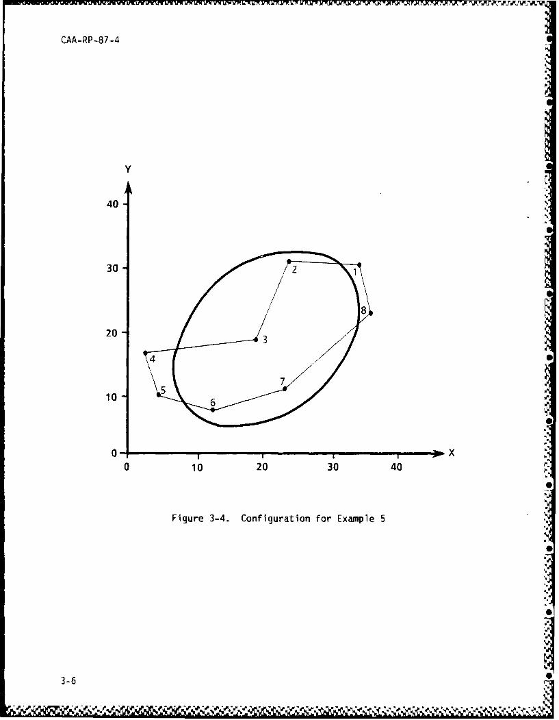
5-6. EXAMPLE 5. Here we have to deal with a nonconvex polygon. There aretwo ways to do this.
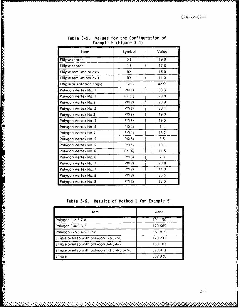
a. The first way is to split the polygon into convex components and addthe resultant areas. For the configuration of Example 5 (see Figure 3-4 andTable 3-5), this can be done by splitting the original polygon into twoconvex parts by a line joining vertices 3 and 7. The resulting areas will beas shown in Table 3-6.
0
0 3-5
CAA-RP-87-4
Y
40,
30- 2
20 - 3
40
10-
0 0
0 10 20 30 40 -
Figure 3-4. Configuration for Example 5
3/-
3-6,-
CAA-RP-87-4
Table 3-5. Values for the Configuration ofExample 5 (Figure 3-4)
Item Symbol Value
Ellipse center XE 19.0
Ellipse center YE 17.8
Ellipse semi-major axis RX 16.0
Ellipse semi-minor axis RY 11.0
Ellipse orientation angle -DEG 42.0-
Polygon Vertex No. 1 PX(1) 33.3
Polygon Vertex No. I PY (1) 29.8
Polygon Vertex No.2 PX(2) 23.9
Polygon Vertex No. 2 PY(2) 30.4
Polygon Vertex No 3 PX(3) 19.0
Polygon Vertex No. 3 PY(3) 19.0
Polygon Vertex No. 4 PX(4) 1.4Polygon Vertex No.4 PY(4) 16.2
Polygon Vertex No 5 PX(5) 3.8
Polygon Vertex No. 5 PY(5) 10.1
Polygon Vertex No. 6 PX (6) 11 5
Polygon Vertex No. 6 PY(6) 73
Polygon Vertex No. 7 PX(7) 23.8
Polygon Vertex No. 7 PY(7) 11 0
Polygon Vertex No. 8 PX(8) 35.5
Polygon Vertex No. 8 PY(8) 23.0
Table 3-6. Results of Method 1 for Example 5
Item Area
Polygon 1-2-3-7-8 191.150
Polygon 3-4-5-6-7 170.665
Polygon 1-2-3-4-5-6-7-8 361.815
Ellipse overlap with polygon 1-2-3-7-8 170.231
Ellipse overlap with polygon 3-4-5-6-7 153 182
Ellipse overlap with polygon 1-2-3-4-5-6-7-8 323.413
Ellipse 552.920
'0 3-.
.*-.J.~~ ~~~~~~~~ v ~ . - . ~ ~ ~ ww ~ ~ '~ V
UWV.P
CAA-RP-87-4
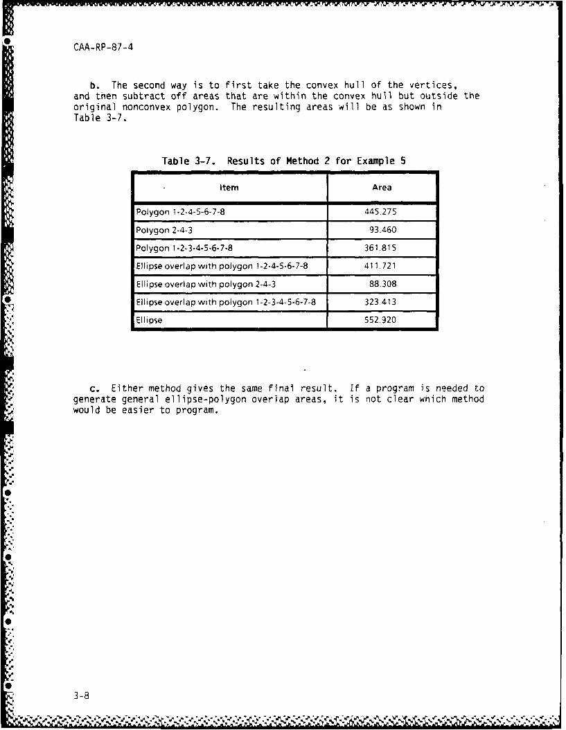
b. The second way is to first take the convex hull of the vertices,and then subtract off areas that are within the convex hull but outside theoriginal nonconvex polygon. The resulting areas will be as shown inTable 3-7.
Table 3-7. Results of Method 2 for Example 5
item Area
Polygon 1-2-4-5-6-7-8 445.275
Polygon 2-4-3 93.460
Polygon 1-2-3-4-5-6-7-8 361.815
Ellipse overlap with polygon 1-2-4-5-6-7-8 411.721
Ellipse overlap with polygon 2-4-3 88.308
Ellipse overlap with polygon 1-2-3-4-5-6-7-8 323.413
Ellipse 552.920
c. Either method gives the same final result. If a program is needed togenerate general ellipse-polygon overlap areas, it is not clear which methodwould be easier to program.
3-8
0
0
-43-
-4-
CAA-RP-87-4
CHAPTER 4
CONCLUSIONS AND OBSERVATIONS
4-1. RESULTS. A simple finite algorithm suffices to calculate the area ofoverlap of an ellipse and a (convex) polygon. The resultant algorithm iswidely applicable in the sense that it gives theoretically exact answers forall possible configurations of the ellipse and the polygon. It is user-friendly in the sense that its implementation involves a straightforwardcomputation whose net result is easily discernible. As a result, thealgorithm should be easy to verify, debug, modify, or incorporate confidentlyinto larger programs. Moreover, the accuracy of the calculated area of over-lap can be assured by using double-precision arithmetic to control roundofferror.
4-2. OBSERVATIONS
a. Practical implementation of the algorithm would be aided by developingsubroutines optimized for speed which could be incorporated into large simu-lations of wargames such as NUFAM, FORCEM, COSAGE, and others.
b. The method yields the exact area of overlap of an ellipse with aconvex polygon. Since a triangle is convex, the method is, in principle,capable of being used to find the exact area of overlap of an ellipse withany region that can be triangulated, i.e., any polygon. Triangulation is notactually necessary--any decomposition of the polygonal region into a finitenumber of disjoint convex polygons is sufficient.
c. Many regions that arise in practice can be approximated by polygons.Hence the method can, in principle, be applied to approximate the area ofoverlap of an ellipse with a fairly arbitrary region of the sort that oftenarises in practice.
d. Although it may not be the most efficient algorithm for the purpose,the method can, in principle, be used to find the area of any polygon. Allthat is necessary is to find the area of overlap of the polygon with a diskwhose radius is sufficiently large that it completely covers the polygon. Ifthe area of overlap does not change when the disk's radius is increasedslightly, then the radius is sufficiently large.
4-1
.. . . -. •
CAA-RP-87-4
APPENDIX A
MATHEMATICAL DEVELOPMENT
A-I. INTRODUCTION
a. This appendix presents the mathematical developments on which the restof the paper are based. Paragraph 1-7, Chapter 1, and Chapter 2 explainedhow the general ellipse-polygon overlap problem is reduced to that of findingthe area of overlap between a disk and a wedge-shaped region. The develop-ment in this appendix shows how to find the vertex angle of the wedge-shapedregion, how to locate the center of the disk with respect to the wedge, andhow the overlap area is computed. Throughout this appendix, it is assumedthat the polygon's vertices have been transformed to the values (X(J), Y(J))by the affine transformation described in Chapter 2, and that the ellipse hasbeen transformed to a disk of radius R centered at (0, 0).
b. Paragraphs A-5 and A-6 on the area of overlap of two disks and tworectangles are also included for reference, although no use of them is madeelswhere in this paper.
A-2. FINDING THE WEDGE'S VERTEX ANGLE
a. Consider the wedge whose vertex coincides with the polygon's vertex J.By virtue of the orientation of the polygon (see paragraph 2-2a), vertex Jhas a preceding vertex JM (mnemonic for J-minus) and a succeeding vertexvertex JP. (mnemonic for J-plus). The unit vector, E, from JM to J hascomponents:
EX = (X(J) - X(JM)) / A
EY = (Y(J) - Y(JM)) / A
where A, the magnitude of the vector from JM to J, is given by:
A = SQR ((X(J) - X(JM)) + (Y(J) - Y(JM))').
The unit vector orthogonal to E and pointing generally toward the interior ofthe polygon has components
E' = (-EY, EX).
b. Think in terms of a local Cartesian coordinate system with origin atvertex J, x-axis along E, and y-axis along E'. Relative to this coordinatesystem, the coordinates (AX, AY) of vertex JP, found by taking the dot-products of the vector from vertex J to JP with E and with E', are:
•-'.
CAA-RP-87-4
AX = EX * (X(JP) - X(J)) + EY * (Y(JP) - Y(J))
AY = - EY * (X(JP) - X(J)) + EX * (Y(JP) - (Y(J))
c. Then the wedge angle GAMMA is found as:
GAMMA = ARG (AX, AY),
where ARG (U, V) is the angle from the x-axis to the line joining the originto the point at (U, V). Note that the polygon is convex at vertex J if, andonly if, GAMMA is less than PI radians.
A-3. FINDING THE COORDINATES OF THE DISK. The coordinates of the diskrelative to the local coordinate system at vertex J are needed for subsequentdevelopments. The local coordinates of a disk centered at coordinates (X0,YD) are found by taking the dot-products of the vector from vertex J to (XD,YD) with E and with E'. They are:
XO = EX * (XD - X(J)) + EY * (YD - Y(J))
YO = - EY * (XD - X(J)) + EX * (YD - Y(J)).
The polar coordinates (RHO, BETA) of the disk's center in the localcoordinate system at vertex J are also useful. They are given by:
RHO SQR (XO2 + Y02 )
BETA : ARG (XO, YO).
Yet another local coordinate system is useful. Its origin is at vertex J.Its x-axis is directed in the positive direction from vertex J to vertex JP,and its y-axis is directed toward the interior of the wedge (and hence awayfrom the interior of the polygon). The coordinates of the disk's center inthis local coordinate system are:
XG = RHO * COS (GAMMA - BETA)
YG = RHO * SIN (GAMMA - BETA)
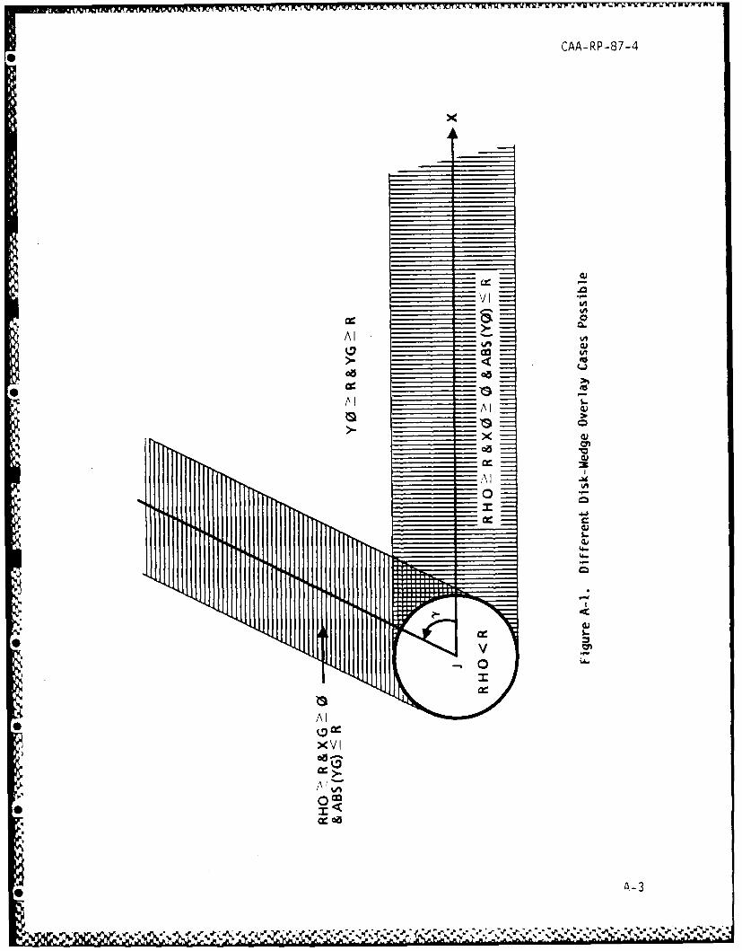
A-4. FINDING THE DISK-WEDGE OVERLAP AREA. THe disk-wedge overlap area isfound by treating the different possible disk-wedge overlap cases that canarise. The possible cases of disk-wedge overlap (for the wedge at vertex J)are illustrated in Figure A-I, and are described in more detail below.
".A-2
U
CAA-RP-87-4
x
(U
Alv i
CA0
M A I
S xvx
00
cc)
,•. ,
-
00
A I.
**
00c
0 A-3
CAA-RP-87-4
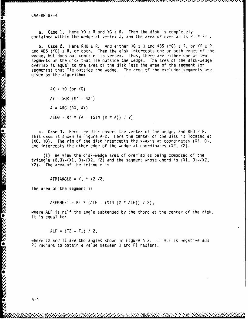
a. Case 1. Here YO 2 R and YG Ž R. Then the disk is completelycontained within the wedge at vertex J, and the area of overlap is PI * R2
b. Case 2. Here RHO Ž R. And either XG Ž 0 and ABS (YG) 5 R, or XO ? Rand ABS (YO) • R, or both. Then the disk intercepts one or both edges of thewedge, but does not contain its vertex. Thus, there are either one or twosegments of the disk that lie outside the wedge. The area of the disk-wedgeoverlap is equal to the area of the disk less the area of the segment (orsegmcnts) that lie outside the wedge. The area of the excluded segments aregiven by the algorithm:
AX = YO (or YG)
AY = SQR (R2 - AX2 )
A = ARG (AX, AY)
ASEG = R' * (A - (SIN (2 * A)) / 2)
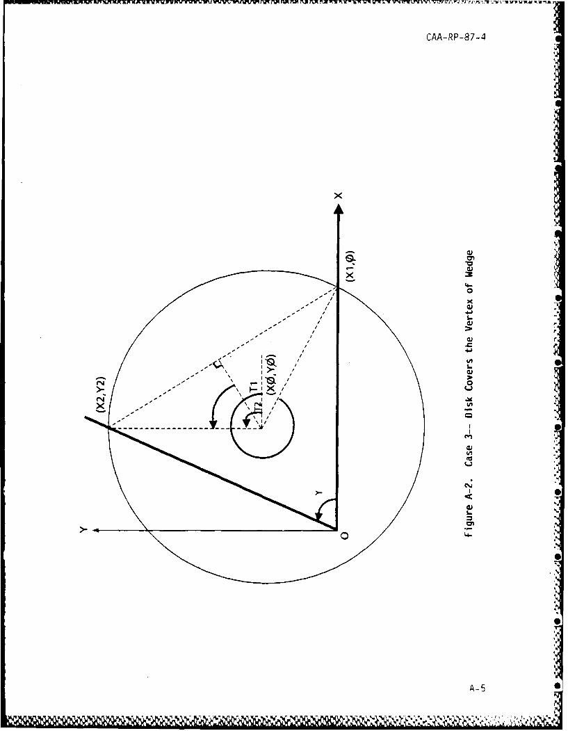
c. Case 3. Here the disk covers the vertex of the wedge, and RHO < R.This case is shown in Figure A-2. Here the center of the disk is located at(XO, YO). The rim of the disk intercepts the x-axis at coordinates (X1, 0),and intercepts the other edge of the wedge at coordinates (X2, Y2).
(1) We view the disk-wedge area of overlap as being composed of thetriangle (O,O)-(XI, O)-(X2, Y2) and the segment whose chord is (XI, O)-(X2,Y2). The area of the triangle is
ATRIANGLE = X1 * Y2 /2.
The area of the segment is
ASEGMENT = R' * (ALF - (SIN (2 * ALF)) / 2),
where ALF is half the angle subtended by the chord at the center of the disk.It is equal to:
ALF = (T2 - TI) / 2,
where T2 and Ti are the angles shown in Figure A-2. If ALF is negative addPI radians to obtain a value between 0 and PI radians.
A-4
Of
CAA-RP-87-4
SL
cu_
di.
----- _
00
A-5 O
w,-,.
[ •';-
CAA-RP-87-4
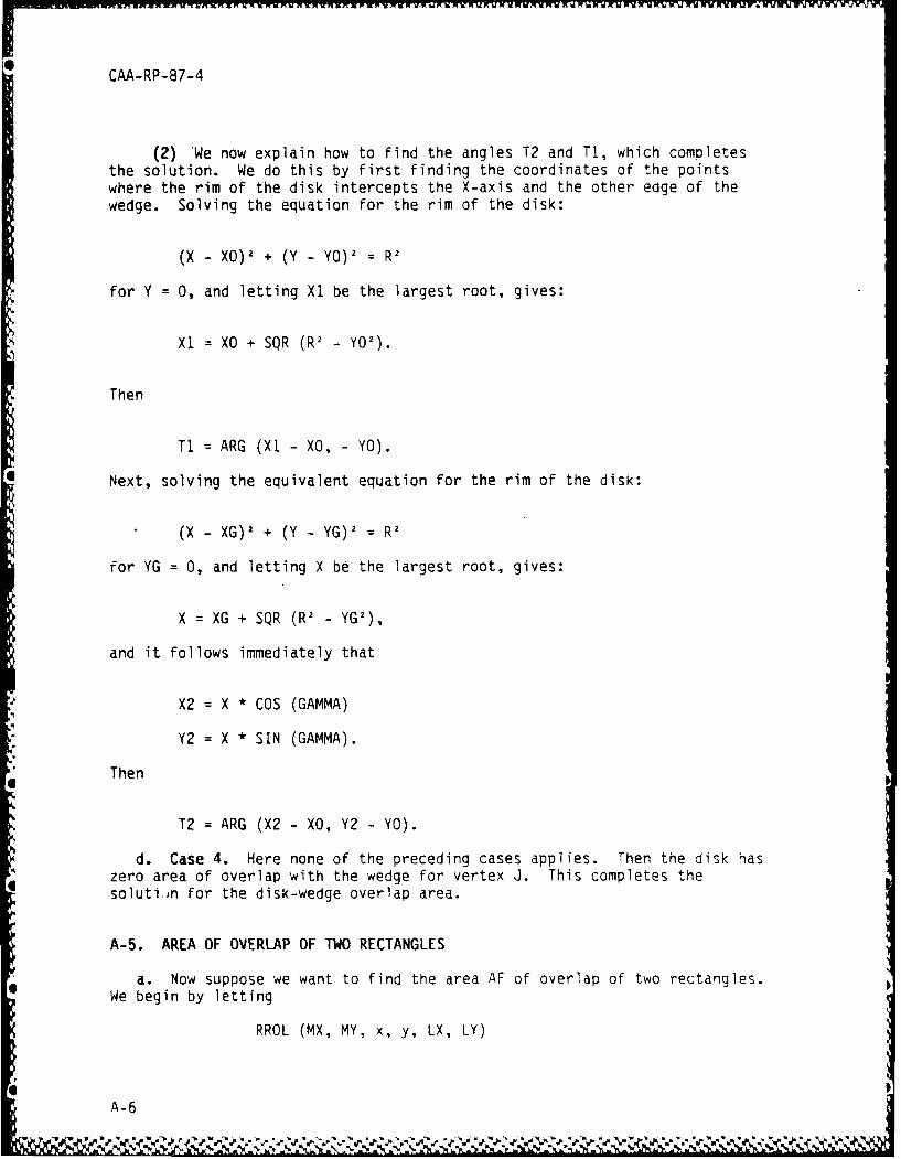
(2) 'We now explain how to find the angles T2 and Ti, which completesthe solution. We do this by first finding the coordinates of the pointswhere the rim of the disk intercepts the X-axis and the other edge of thewedge. Solving the equation for the rim of the disk:
(X - XO) 2 + (Y - YO) 2 = R1
for Y = 0, and letting Xl be the largest root, gives:
X1 = XO + SQR (R2 - Y02 ).
Then
Ti = ARG (XI - XO, - YO).
Next, solving the equivalent equation for the rim of the disk:
(X - XG) 2 + (Y - YG) 2 = R2
for YG = 0, and letting X be the largest root, gives:
X = XG + SQR (RI - YG2 ),
and it follows immediately that
X2 = X * COS (GAMMA)
Y2 = X * SIN (GAMMA).
Then
T2 = ARG (X2 - XO, Y2 - YO).
d. Case 4. Here none of the preceding cases applies. Then the disk haszero area of overlap with the wedge for vertex J. This completes thesoluti n for the disk-wedge overlap area.
A-5. AREA OF OVERLAP OF TWO RECTANGLES
a. Now suppose we want to find the area AF of overlap of two rectangles.We begin by letting
RROL (MX, MY, x, y, LX, LY)
A-6
*_ CAA-RP-87-4
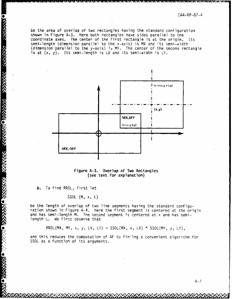
be the area of overlap of two rectangles having the standard configurationshown in Figure A-3. Here both rectangles have sides parallel to thecoordinate axes. The center of the first rectangle is at the origin. Itssemi-length (dimension parallel to the x-axis) is MX and its semi-width(dimension parallel to the y-axis) is MY. The center of the second rectangleis at (x, y). Its semi-length is LX and its semi-width is LY.
I (x +Lx,y + Ly)
L (x,y)
-MX,-MY
Figure A-3. Overlap of Two Rectangles(see text for explanation)
b. To find RROL, first let
SSOL (M, x, L)
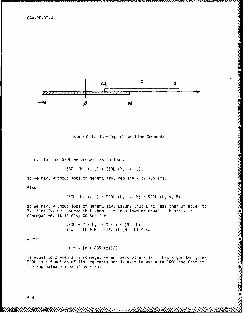
be the length of overlap of two line segments having the standard configu-ration shown in Figure A-4. Here the first segment is centered at the originand has semi-length M. The second segment is centered at x and has semi-length L. We first observe that
RROL(MX, MY, x, y, LX, LY) = SSOL(MX, x, LX) * SSOL(MY, y, LY),
and this reduces the computation of AF to fin,'ing a convenient algorithm forSSOL as a function of its arguments.
0
* A-7
CAA-RP-87-4
X-L X X +L
-M 0 M
Figure A-4. Overlap of Two Line Segments
c. To find SSOL we proceed as follows.
SSOL (M, x, L) = SSOL (M, -x, L),
so we may, without loss of generality, replace x by ABS (x).
Also
SSOL (M, x, L) = SSOL (L, -x, M) = SSOL (L, x, M),
so we may, without loss of generality, assume that L is less than or equal toM. Finally, we observe that when L is less than or equal to M and x isnonnegative, it is easy to see that
SSOL = 2 * L, if 0 : x 5 (M - L),SSOL = IL + M - x)+, if (M - L) • x,
where
[zl+ = [z + ABS (z)I/2
is equal to z when z is nonnegative and zero otherwise. This algorithm givesSSOL as a function of its arguments and is used tn evaluate RROL and from itthe approximate area of overlap.
A-8
.. A -A - .
CAA-RP-87-4
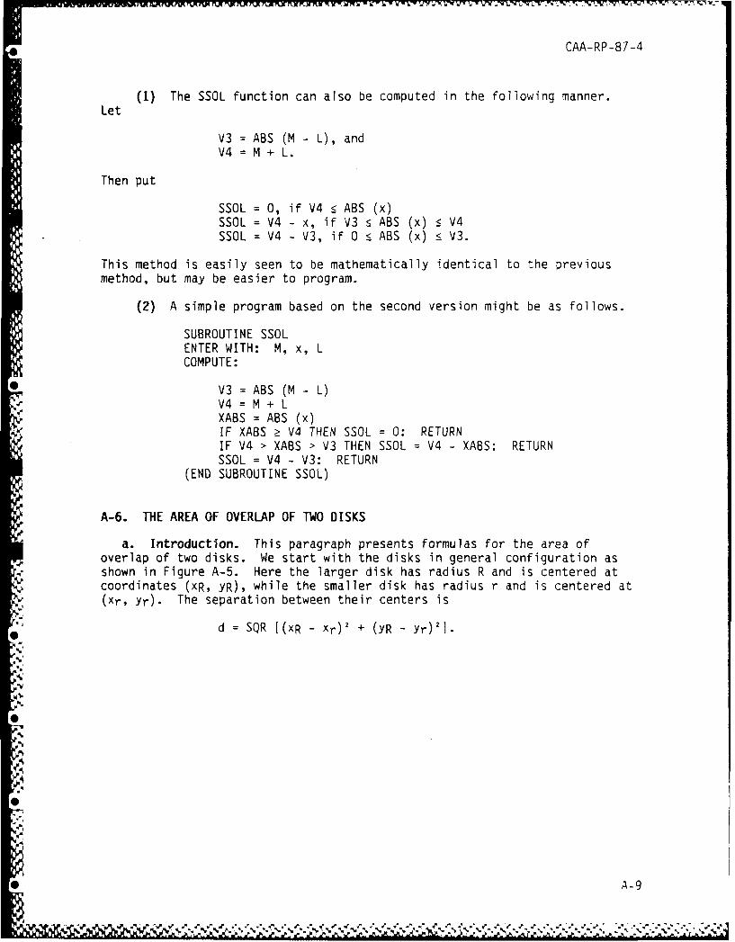
(1) The SSOL function can also be computed in the following manner.Let
V3 = ABS (M - L), andV4 = M + L.
Then put
SSOL = 0, if V4 5 ABS (x)SSOL = V4 - x, if V3 s ABS (x) • V4SSOL = V4 - V3, if 0 : ABS (x) !' V3.
This method is easily seen to be mathematically identical to the previousmethod, but may be easier to program.
(2) A simple program based on the second version might be as follows.
SUBROUTINE SSOLENTER WITH: M, x, LCOMPUTE:
0 V3 = ABS (M - L)'V4 = M + LXABS = ABS (x)IF XABS Ž V4 THEN SSOL = 0: RETURNIF V4 > XABS > V3 THEN SSOL = V4 - XABS: RETURNSSOL = V4 - V3: RETURN
(END SUBROUTINE SSOL)
A-6. THE AREA OF OVERLAP OF TWO DISKS
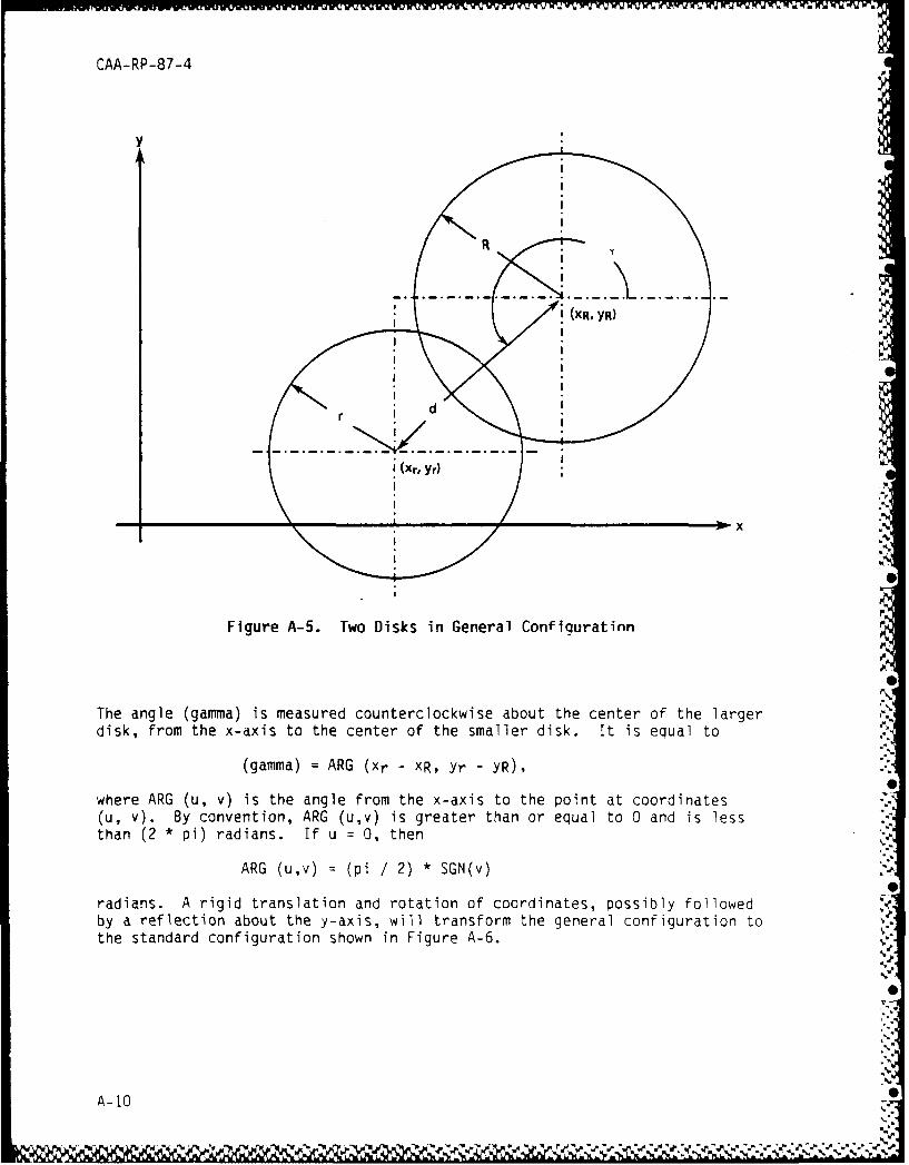
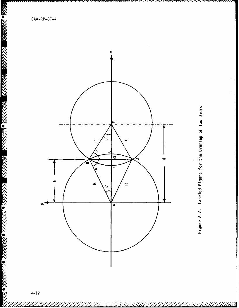
a. Introduction. This paragraph presents formulas for the area ofoverlap of two disks. We start with the disks in general configuration asshown in Figure A-5. Here the larger disk has radius R and is centered atcoordinates (xR, YR), while the smaller disk has radius r and is centered at(xr, Yr). The separation between their centers is
d : SQR I(xR - xr) 2 + (YR - Yr)'1.
0 -
CAA-RP-87-4
y
RI
: '•i (XR, YR)
' i'
r I d
i (Xr, YrO
x
Figure A-5. Two Disks in General Configuratinn
The angle (gamma) is measured counterclockwise about the center of the largerdisk, from the x-axis to the center of the smaller disk. It is equal to
(gamma) = ARG (xr - XR, Yr - YR),
where ARG (u, v) is the angle from the x-axis to the point at coordinates(u, v). By convention, ARG (u,v) is greater than or equal to 0 and is lessthan (2 * pi) radians. If u = 0, then
ARG (u,v) = (pi / 2) * SGN(v)
radians. A rigid translation and rotation of coordinates, possibly followedby a reflection about the y-axis, will transform the general configuration tothe standard configuration shown in Figure A-6.
A-100
6ýNkd ýN.
CAA-RP-87-4
y
£x
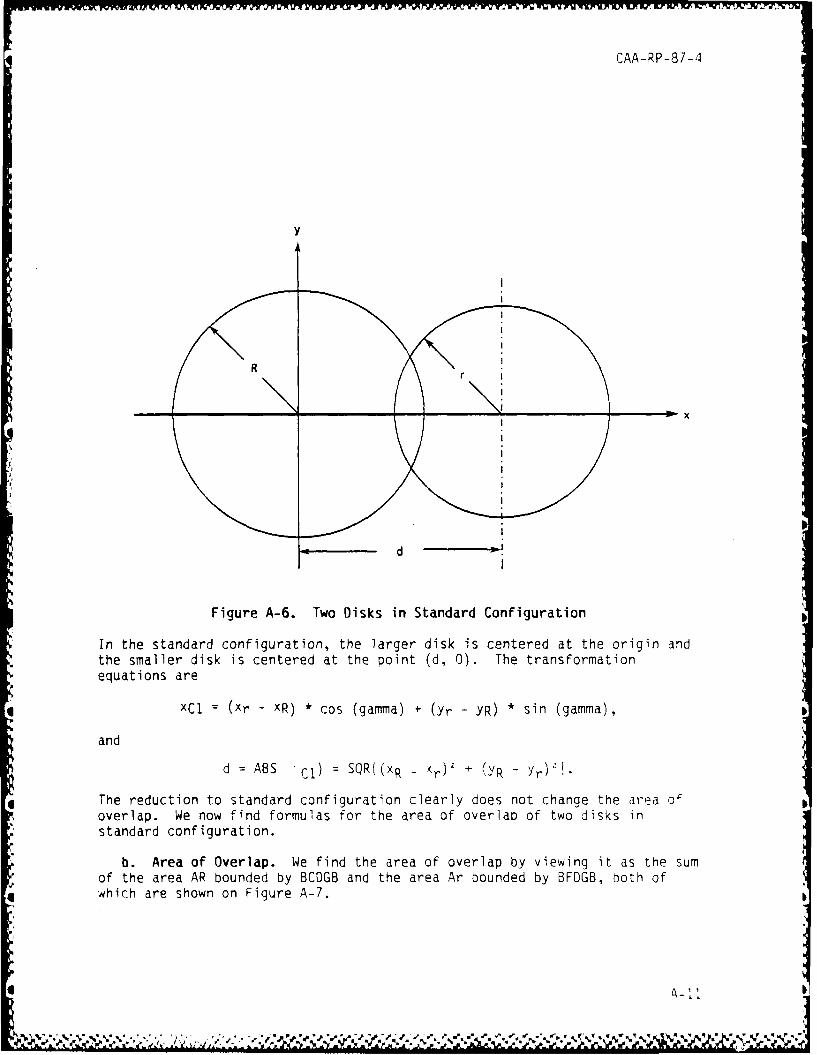
Figure A-6. Two Disks in Standard Configuration
* In the standard configuration, the larger disk is centered at the origin andthe smaller disk is centered at the point (d, 0). The transformationequations are
* xCl = (xr - XR) *cos (gamma) + (Yr - YR) * sin (gamma),
and
I2
d = ABS C-j) =SQR((xR - )(r + (YR - Yr)'I.
* The reduction to standard configuration clearly does not change the area ofoverlap. We now find formulas for the area of overlap of two disks instandard configuration.
b. Area of Overlap. We find the area of overlap by viewing it as the sumof the area AR bounded by BCDGB and the area Ar bounded by BFDGB, both of
* .4 hc r hw nFigure A- 7.TwDisinSadr Co ig at n
esndr confgu e la e d k is c e at te o in d
" tesale ikiscnee attepit(,0.Tetasomto
- - - --- .-. - -.. - .t- t % - it t�
0CAA-RP-87-4
x
U.' 0-.---------. .-.-.-.-.-.-. .-. 3* 1.
1 '4-
I 0
* I- I 'a
I -
0w
I-0
'4-
is 0.1ii.
'U
S I 0.1+ 0J
'a-�
0P Ii.-.
0.1L
* -
0
0
0�-I2
CAA-RP-87-4
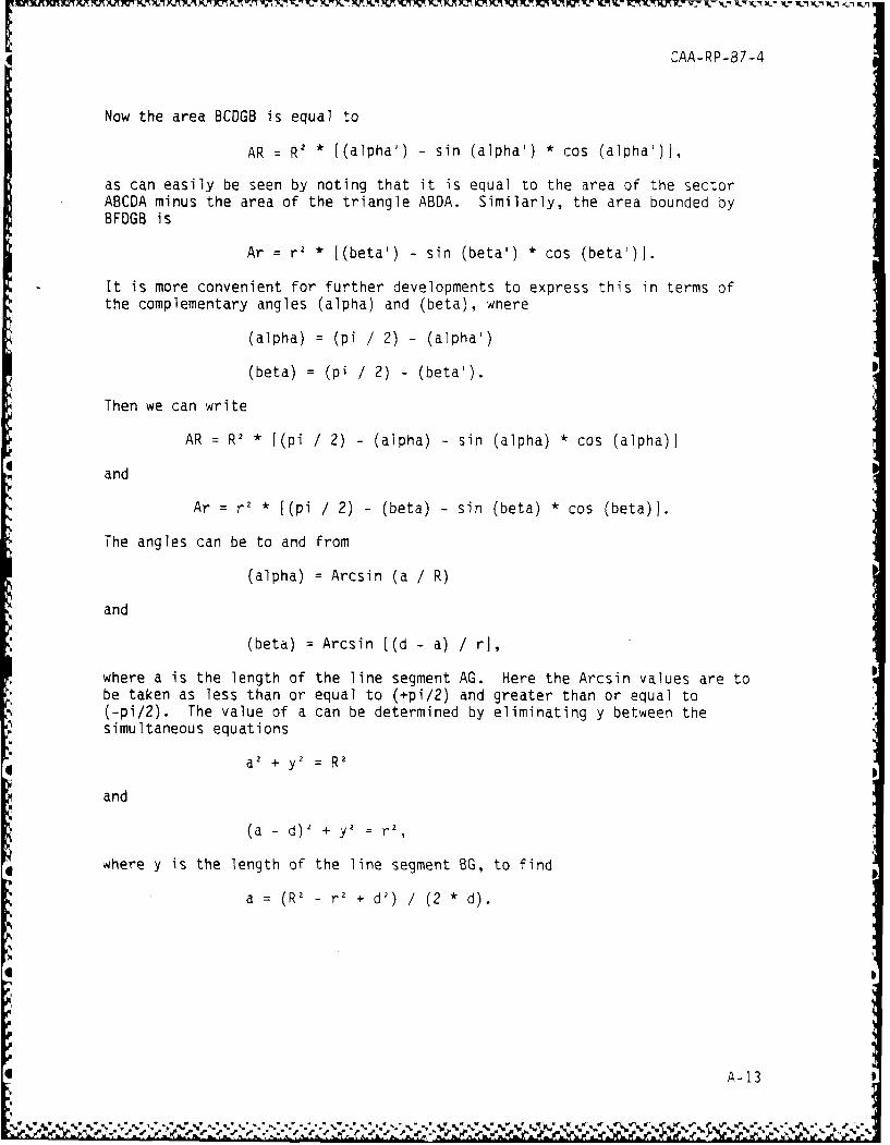
Now the area 8CDGB is equal to
AR = R2 * ((alpha') - sin (alpha') * cos (alpha')f,
as can easily be seen by noting that it is equal to the area of the sectorABCDA minus the area of the triangle ABDA. Similarly, the area bounded byBFDGB is
Ar = r2 * [(beta') - sin (beta') * cos (beta')j.
It is more convenient for further developments to express this in terms ofthe complementary angles (alpha) and (beta), where
(alpha) = (pi / 2) - (alpha')
(beta) = (pi /2) -(beta').
Then we can write
AR = RI * [(pi / 2) - (alpha) - sin (alpha) * cos (alpha)I
and
Ar = r2 * [(pi / 2) - (beta) - sin (beta) * cos (beta)).
The angles can be to and from
(alpha) = Arcsin (a / R)
and
(beta) : Arcsin [(d - a) / r],
where a is the length of the line segment AG. Here the Arcsin values are tobe taken as less than or equal to (+pi/2) and greater than or equal to(-pi/2). The value of a can be determined by eliminating y between thesimultaneous equations
a 2 + y2 = R2
and
(a -d) 2 + y = r2,
where y is the length of the line segment BG, to find
a = (RI - r2 + d') / (2 * d).
A-13
S. .. ,. , . , . .. . , , . , .. . . . . . . . . . . . .- . , .
* CAA-RP-87-4
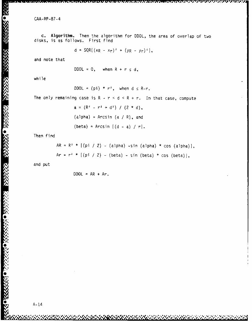
c. Algorithm. Then the algorithm for DDOL, the area of overlap of twodisks, is as follows. First find
d = SQR[(xR - xr) 2 + (YR - Yr)21,
and note that
DDOL = O, when R + r <_ d,
while
DOOL = (pi) * r', when d _< R-r.
The only remaining case is R - r < d < R + r. In that case, compute
a = (RI - r' + d2) / (2 * d),
(alpha) = Arcsin (a / R), and
(beta) Arcsin [(d - a) / ri.
Then find
AR = RI * [(pi / 2) - (alpha) -sin (alpha) * cos (alpha)],
Ar = r' * [(pi / 2) - (beta) - sin (beta) * cos (beta)J,
and put
DOOL = AR + Ar.
A.
0 A-14
CAA-RP-87-4
APPENDIX B
COMPUTER PROGRAMS
B-i. INTRODUCTION. This appendix presents the listing and notes for asubroutine that implements the algorithms described in Appendix A and wasused to obtain the results presented in Chapter 3.
B-2. PROGRAM NOTES
a. The subroutine is called EPOL, for "Ellipse-Polygon Overlap." Itslisting is at paragraph B-3. Notes on it are provided below.
b. EPOL's inputs are as follows.
(1) XE = x-coordinate of the center of the ellipse.
(2) YE = y-coordinate of the center of the ellipse.
(3) RX = the semi-major axis of the ellipse.
(4) RY = the semi-minor axis of the ellipse.
(5) TDEG = orientation angle of the ellipse, in degrees. The orien-tation angle is the angle between the semi-major axis of the ellipse(prolonged if necessary) and the x-axis. It is conventionally restricted tobe greater than -90 degrees and less than or equal to +90 degrees.
(6) (PX(J), PY(J)) = coordinates of the polygon's vertices, listed incounterclockwise order around the perimeter of the polygon. Here J runs fromI to the number of vertices in the polygon.
c. EPOL's outputs are:
(1) DWOL(J) = disk-wedge overlap areas for each wedge. Here J runsfrom I to the number of vertices in the polygon. Note that these areas applyafter the affine transformation described in Chapter 2 has reduced theellipse to a disk.
(2) EPOL = ellipse-polygon overlap area.
d. EPOL is written in the APPLESOFT Basic language, which runs on APPLE11 computers.
e. In line 3010, the call to subroutine 9030 prompts for the number N ofvertices and for their coordinates PX(J), PY(J).
f. In line 3020, the call to subroutine 9110 prompts for the polygon'scoordinates PX(J), PY(J).
*• B-I
CAA-RP-87-4
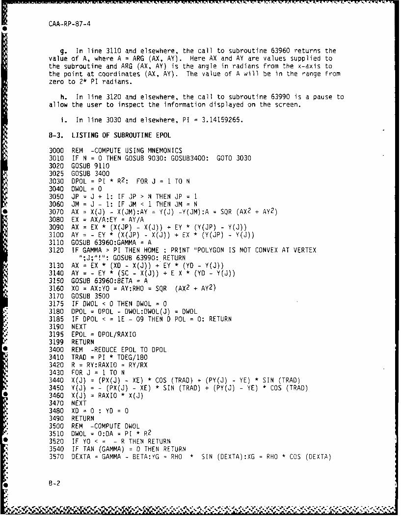
g. In line 3110 and elsewhere, the call to subroutine 63960 returns thevalue of A, where A = ARG (AX, AY). Here AX and AY are values supplied tothe subroutine and ARG (AX, AY) is the angle in radians from the x-axis tothe point at coordinates (AX, AY). The value of A will be in the range fromzero to 2* PI radians.
h. In line 3120 and elsewhere, the call to subroutine 63990 is a pause toallow the user to inspect the information displayed on the screen.
i. In line 3030 and elsewhere, PI = 3.14159265.
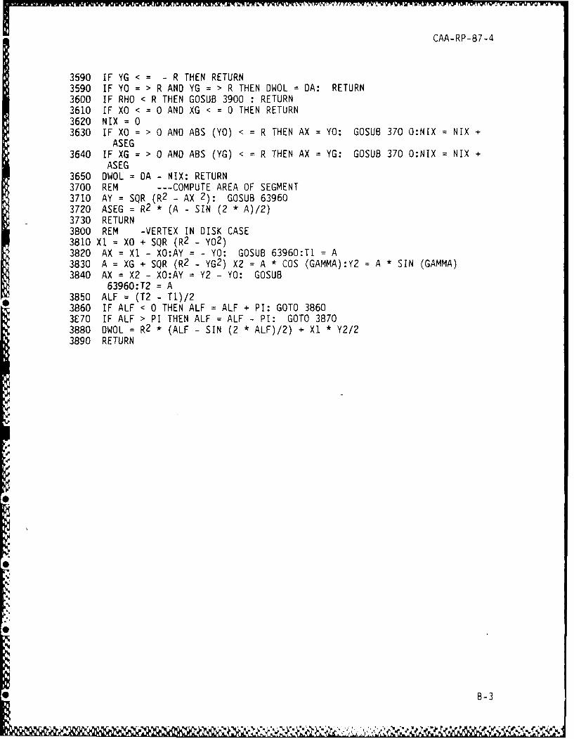
B-3. LISTING OF SUBROUTINE EPOL
3000 REM -COMPUTE USING MNEMONICS3010 IF N = 0 THEN GOSUB 9030: GOSUB3400: GOTO 30303020 GOSUB 91103025 GOSUB 34003030 DPOL = PI * R2 : FOR J = I TO N3040 DWOL = 03050 JP = J + 1: IF JP > N THEN JP = 13060 JM = J - 1: IF JM < I THEN JM = N3070 AX = X(J) - X(JM):AY = Y(J) -Y(JM):A = SQR (AX2 + AY2)3080 EX = AX/A:EY = AY/A3090 AX = EX * (X(JP) - X(J)) + EY * (Y(JP) - Y(J))3100 AY = - EY * (X(JP) - X(J)) + EX * (Y(JP) - Y(J))3110 GOSUB 63960:GAMMA = A3120 IF GAMMA > PI THEN HOME : PRINT "POLYGON IS NOT CONVEX AT VERTEX
";J;"!": GOSUB 63990: RETURN3130 AX = EX * (XD - X(J)) + EY * (YD - Y(J))3140 AY = - EY * (SC - X(J)) + E X * (YD - Y(J))3150 GOSUB 63960:BETA = A3160 XO = AX:YO = AY:RHO = SQR (AX2 + AY2 )3170 GOSUB 35003175 IF DWOL < 0 THEN DWOL = 03180 DPOL = DPOL - DWOL:DWOL(J) = DWOL3185 IF OPOL < = IE - 09 THEN D POL = 0: RETURN3190 NEXT3195 EPOL = OPOL/RAXIO3199 RETURN3400 REM -REDUCE EPOL TO OPOL3410 TRAD = PI * TDEG/1803420 R = RY:RAXIO = RY/RX3430 FOR J 1 TO N3440 X(J) = (PX(J) - XE) * COS (TRAD) + (PY(J) - YE) * SIN (TRAD)3450 Y(J) = - (PX(J) - XE) * SIN (TRAD) + (PY(J) - YE) * COS (TRAD)3460 X(J) RAXIO * X(J)3470 NEXT3480 XD = 0 : YD =3490 RETURN3500 REM -COMPUTE DWOL3510 DWOL = O:DA = PI * R23520 IF YO < = R THEN RETURN3540 IF TAN (GAMMA) = 0 THEN RETURN3570 DEXTA GAMMA - BETA:YG = RHO * SIN (DEXTA):XG = RHO * COS (DEXTA)
B-2
CAA-RP-87-4
3590 IF YG < : - R THEN RETURN3590 IF YO = > R AND YG = > R THEN DWOL = DA: RETURN3600 IF RHO < R THEN GOSUB 3900 : RETURN3610 IF XO < = 0 AND XG < = 0 THEN RETURN3620 NIX = 03630 IF XO = > 0 AND ABS (YO) < = R THEN AX = YO: GOSUB 370 O:NIX = NIX +
ASEG3640 IF XG = > 0 AND ABS (YG) < = R THEN AX = YG: GOSUB 370 O:NIX = NIX +
ASEG3650 OWOL = DA - NIX: RETURN3700 REM --- COMPUTE AREA OF SEGMENT3710 AY = SQR (R2 - AX 2): GOSUB 639603720 ASEG = R2 * (A - SIN (2 * A)/2)3730 RETURN3800 REM -VERTEX IN DISK CASE3810 XI = XO + SQR (R2 - Y02 )3820 AX = XI - XO:AY = - YO: GOSUB 63960:T1 = A3830 A = XG + SQR (R2 - YG2 ) X2 = A * COS (GAMMA):Y2 = A * SIN (GAMMA)3840 AX = X2 - XO:AY = Y2 - YO: GOSUB
63960:T2 A3850 ALF (T2 - T)/23860 IF ALF < 0 THEN ALF = ALF + PI: GOTO 38603E70 IF ALF > PI THEN ALF = ALF - PI: GOTO 38703880 DWOL = R2 * (ALF - SIN (2 * ALF)/2) + Xl * Y2/23890 RETURN
dB-3
* CAA-RP-87-4
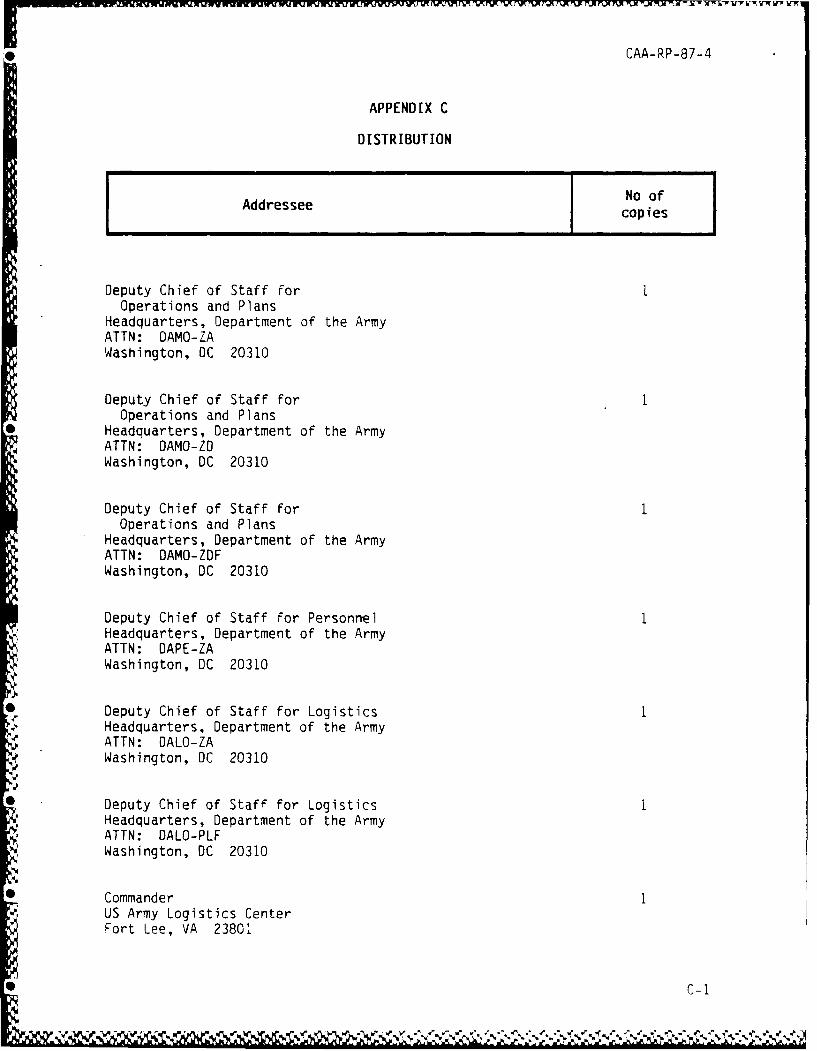
APPENDIX C
DISTRIBUTION
Addressee No ofcopies
Deputy Chief of Staff forOperations and Plans
Headquarters, Department of the ArmyATTN: DAMO-ZAWashington, DC 20310
Deputy Chief of Staff for IOperations and Plans
Headquarters, Department of the ArmyATTN: DAMO-ZDWashington, DC 20310
Deputy Chief of Staff forOperations and Plans
Headquarters, Department of the ArmyATTN: DAMO-ZDFWashington, DC 20310
Deputy Chief of Staff for Personnel 1Headquarters, Department of the ArmyATTN: DAPE-ZAWashington, DC 20310
Deputy Chief of Staff for Logistics 1Headquarters, Department of the ArmyATTN: DALO-ZAWashington, DC 20310
Deputy Chief of Staff for LogisticsHeadquarters, Department of the ArmyATTN: DALO-PLFWashington, DC 20310
CommanderUS Army Logistics CenterFort Lee, VA 23801
C-I
4 CAA-RP-87-4
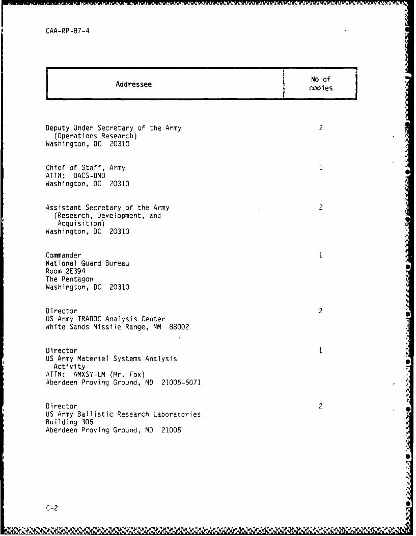
Addressee No ofcopies
Deputy Under Secretary of the Army 2(Operations Research)
Washington, DC 20310
Chief of Staff, Army 1ATTN: DACS-OMOWashington, DC 20310
Assistant Secretary of the Army 2(Research, Development, andAcquisition)
Washington, DC 20310
Commander INational Guard BureauRoom 2E394The PentagonWashington, DC 20310
Director 2US Army TRADOC Analysis Centerdhite Sands Missile Range, NM 88002
Director 1US Army Materiel Systems Analysis
ActivityATTN: AMXSY-LM (Mr. Fox)Aberdeen Proving Ground, MD 21005-5071
Director 2US Army Ballistic Research LaboratoriesBuilding 305Aberdeen Proving Ground, MD 21005
S
C-2 S,%
CAA-RP-87-4
No ofAddressee copies
Commander 2Combined Arms Combat Development
ActivityFort Leavenworth, KS 66027
CommanderForeign Science and Technology Center227th Street NECharlottesville, VA 22901
Director 2Defense Nuclear AgencyATTN: LASS6801 Telegraph RoadAlexandria, VA 20305
CommanderArmy Research Institute5001 Eisenhower AvenueAlexandria, VA 22333
CommanderUS Army Logistics Evaluation AgencyNew Cumberland Army DepotNew Cumberland, PA 17070
DirectorDefense Logistics Studies Information
ExchangeUS Army Logistics Management CenterFort Lee, VA 23801
Defense Technical Information Center 2ATTN: DTIC-DDACameron StationAlexandria, VA 22314-6145
* C-3
CAA-RP-87-4
e No ofAddressee copies
US Army Nuclear and Chemical Agency7500 Backlick Road, Bldg #2073ATTN: LibrarySpringfield, VA 22150
Commander 2Air Mobility Research and Development
LaboratoryEustis DirectorateFort Eustis, VA 23604
Commander 2US Army Mobility Equipment Research
and Development CommandFort Belvoir, VA 22060
Commander 2US Army Research, Development, and
Acquisition Information SystemsAgency
Radford, VA 24141
The Pentagon Library (Army Studies 2Section)
ATTN: ANRAL-RSThe PentagonWashington, DC 20310
CommanderUS Army Forces CommandATTN: AFOP-OMFort McPherson, GA 30330
*• C-4
4 CAA-RP-87-4
No ofAddressee copies
Director 2Program Analysis and EvaluationOffice of the Secretary of DefenseRoom 2E330The PentagonWashington, DC 20310
Organization of the Joint Chiefs 2of Staff
ATTN: J-8Room 1D936, The PentagonWashington, DC 20310
Joint Deployment Agency 2Deploying Systems DivisionMacDill Air Force Base, FL 33608
Commandant 2US Army War CollegeCarlisle Barracks, PA 17013
Commandant IUS Army War CollegeATTN: LibraryCarlisle Barracks, PA 17013
Air University 2ATTN: AU CADRE/WGTA (Capt. Taylor)Maxwell Air Force Base, AL 36112-5000
Commandant 2US Air War CollegeMaxwell Air Force Base, AL 36112-5532
C-5
_0 CAA-RP-87-4
No ofAddressee copies
Commandant 2US Navy War CollegeNewport , RI 02840
President 2National Defense UniversityATTN: NDU-LD-CDCWa:hinqton, DC 20319-6000
Commandant 2Armed Forces Staff CollegeNorfolk, VA 23511
Commandant 2US Army Command and General Staff CollegeFort Leavenworth, KS 66027
Commandant 2US Army Command and General Staff CollegeATTN: Department of Combat Development,
Force DevelopmentFort Leavenworth, KS 66027
Superintendent 2United States Military AcademyATTN: Mathematics DepartmentWest Point, NY 10996
Superintendent 2United States Military AcademyATTN: Engineering DepartmentWest Point, NY 10996
Superintendent 2Naval Postgraduate SchoolMonterey, CA 93940
C-6
"( *iW '. N&%!"5 . -e 4•:;•• r~r K I I .
: CAA-RP-87-4
No of
Addressee copies
Naval Postgraduate School 1
ATTN: Department of Operations ResearchCode 55PY (Professor Parry)
Monterey, CA 93940
CommandantUS Army Infantry SchoolATTN: ATSH-IVTFort Benning, GA 31905
CommandantUS Army Armor SchoolATTN: ATSB-CDFort Knox, KY 40121-5215
Commandant 1
US Army Field Artillery SchoolFort Sill, OK 73503
Commandant 1
US Army Air Defense SchoolFort Bliss, TX 79916
Commandant 1
US Army Aviation SchoolFort Rucker, AL 36360
Commandant .US Army Engineer SchoolFort Belvoir, VA 22060
Commandant IUS Army Transportation School
Fort Eustis, VA 23604
C
C-7 S
- .~\~ *pJ'* ~*tA~~ ~ \j'j' ~ '~ %-~.2*~,q~ ~~.' %'
CAA-RP-87-4
No ofAddressee copies
CommandantUS Army Intelligence Center and SchoolATTN: ATSI-TDFort Huachuca, AZ 85613
Commander in ChiefUnited States Readiness CommandATTN: RCDAMacDill Air Force Base, FL 33608
CommanderUS Army Combat Developments
Experimentation CommandFort Ord, CA 93941
DirectorUS Army Human Engineering LaboratoryAberdeen Proving Ground, MD 21005-5001
CINCPAC StaffC3S ASIIBox 32ACamp Smith, HI 96861
CommanderUS Army Western CommandATTN: APOP-SPMFort Shafter, HI 96858-5100
CommanderUS Army Information Systems CommandFort Belvoir, VA 22060
* C-8
NAN
CAA-RP-87-4
I No ofAddressee copies
CommanderEighth US ArmyAPO San Francisco 96301
CommanderUS Army, JapanATTN: AJCSAPO San F-ancisco 96343
Deputy Chief of Staff 1for Intelligence
Headquarters, Department of the ArmyWashington, DC 20310
Commander, USAITACAIAIT-HI, Tech InfoBldg 203, STOP 314Washington Navy YardWashington, DC 20374
Commander/DirectorUS Army Engineer Studies CenterCasey Building, No. 2594
*" Fort Belvoir, VA 22060
CommanderUS Army Corps of Engineers20 Massachusetts Avenue, NWWashington, DC 20314-1000
CommanderUS Army Missile CommandRedstone Arsenal, AL 35898-5090
* C-9
4 CAA-RP-87-4
No ofAddressee copies
CommanderUS Army Ballistic Missile Defense
Systems CommandHuntsville, AL 35807
Commander in Chief,US Army, Europe & Seventh ArmyATTN: AEAGFAPO New York 09403
Commander in ChiefUS Army, Europe & Seventh ArmyATTN: AEAGX-OR (Dr. Leake)APO New York 09403
CommanderUS Army Training and Doctiine CommandATTN: ATCD-AUFort Monroe, VA 23651
CommanderUS Army Training and Doctrire CommandFort Monroe, VA 23651
CommanderUS Army Materiel Command5001 Eisenhower AvenueAlexandria, VA 22333
CcmmanderUS Army Tank-Automotive CommandWarren, MI 48090
CommanderUS Army Information Systems CommandFort Huachuca, AZ 85613
4C-bO
* CAA-RP-87-4
No ofAddressee copies
US Army CE CommandProgram Analysis and EvaluationSystems Analysis DivisionFort Monmouth, NJ 07703
Air Force Center for Studies 2and Analyses
AFCSA/SAMIRoom 1D363, PentagonWashington, DC 20330-5425
Headquarters, US Air ForceOffice of Worldwide Management
of Studies & AnalysesATTN: AF/SALThe PentagonWashington, DC 20330
Air UniversityCommand Readiness Exercise System (CRES)ATTN: Program Management OfficeMaxwell Air Force Base, AL 36112
CommanderTactical Air CommandTAC Analysis GroupLangley Air Force Base, VA 23665
Joint Studies Group (TAC)ATTN: OSSLangley Air Force Base, VA 23665
CommanderUSAF Systems CommandAndrews Air Force BaseWashington, DC 20334
* C-1i
CAA-RP-87-4
No ofAddressee copies
.Commandant
Air Force Institute of TechnologyATTN: AFIT-ENWright-Patterson Air Force Base, OH 45433
HeadquartersRome Air Oevelopment Center (AFSC)ATTN: COAM (Mr. T. Humiston)Griffiss Air Force Base, NY 13441
SCenter for WargamingNaval War CollegeATTN: Naval Warfare Gaming SystemCode 33Newport, RI 02840
President 2Center for Naval Analyses4401 Ford AvenuePost Office Box 16268Alexandria, VA 22302-0268
Naval Research Laboratory 2ATTN: Code 57044555 Overlook AvenueWashington, DC 20375
Chief of Naval Operations 2ATTN: OP-96Room 4A526, PentagonWashington, DC 20350
CommanderNaval Air Systems CommandATTN: Mission and Effectiveness
Analysis Division (AIR-5264)Washington, DC 20361
C-12
CAA-RP-87-4
Addressee No ofI copies
CommanderMilitary Sealift CommandShip Operations Branch4228 Wisconsin AvenueWashington, DC 20390
CommanderNaval Sea Systems CommandCode 09B5Washington, DC 20361
US Army Liaison OfficerNaval Weapons CenterChina Lake, CA 93555
US LNOSupreme Allied Commander AtlanticNorfolk, VA 23511-5100
Marine Corps Operations Analysis Group 2Center for Naval Analyses4401 Ford AvenueP. 0. Box 11280Alexandria, VA 22302-0268
Director 2USMC Development and Education CenterQuantico, VA 22134
Internal Distribution:
Helmbold 15DeRiggi 15Unclassified Library 2
4 C-13
CAA-RP-87-4
GLOSSARY
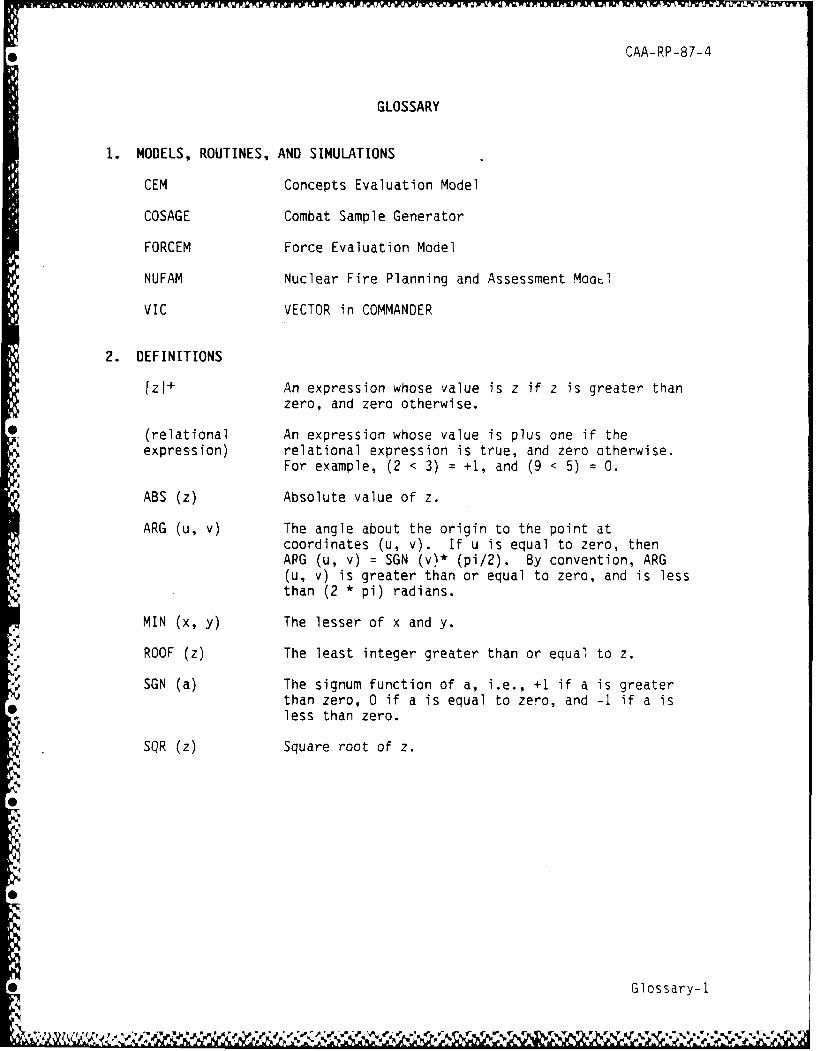
1. MODELS, ROUTINES, AND SIMULATIONS
CEM Concepts Evaluation Model
COSAGE Combat Sample Generator
FORCEM Force Evaluation Model
NUFAM Nuclear Fire Planning and Assessment Moot!
VIC VECTOR in COMMANDER
2. DEFINITIONS
[z]+ An expression whose value is z if z is greater thanzero, and zero otherwise.
(relational An expression whose value is plus one if theexpression) relational expression is true, and zero otherwise.
For example, (2 < 3) = +1, and (9 < 5) = 0.
ABS (z) Absolute value of z.
ARG (u, v) The angle about the origin to the point atcoordinates (u, v). If u is equal to zero, thenARG (u, v) = SGN (v)* (pi/2). By convention, ARG(u, v) is greater than or equal to zero, and is lessthan (2 * pi) radians.
MIN (x, y) The lesser of x and y.
ROOF (z) The least integer greater than or equal to z.
SGN (a) The signum function of a, i.e., +1 if a is greaterthan zero, 0 if a is equal to zero, and -1 if a isless than zero.
SQR (z) Square root of z.
Glossary-i
'r W
AN ALGORITHM FOR CALCULATING STUDYCAA THE AREA OF OVERLAP OF AN SUMMARY
ELLIPSE AND A CONVEX POLYGON CAA-RP-87-4
THE REASON FOR PERFORMING THIS STUDY was to develop and document animproved algorithm for determining in computer simulations the area ofoverlap of an ellipse and a convex polygon.
THE PRINCIPAL FINDINGS are that a useful algorithm can be developed fordetermining in computer simulations the area of overlap of an ellipse and aconvex polygon. It appears to be a new method offering many advantages overthose previously proposed.
THE MAIN ASSUMPTION is that the polygon is convex.
THE PRINCIPAL LIMITATION is that numerical roundoff error may, under someconditions, reduce the accuracy of the result.
THE SCOPE OFTHE WORK is limited to determining the area of overlap of anellipse and a convex polygon.
THE RESEARCH OBJECTIVE was to develop and document an algorithm fordetermining in computer simulations the area of overlap of an ellipse and aconvex polygon.
THE WORK WAS SUPPORTED BY the US Army Concepts Analysis Agency.
*;


![[NAME REMOVED]. What is a Polygon? A polygon has at least three or more sides to form a convex or irregular shape. -Therefore the interior angles of](https://img.pdfslide.us/doc/110x75/56649d9d5503460f94a86f8f/name-removed-what-is-a-polygon-a-polygon-has-at-least-three-or-more.jpg)