Embed Size (px)
Citation preview
Elflex Flexible Couplings
Flexible CouplingsCEF-2.00GB0312
We can create custom engineered transmission solutions of any size and configuration.
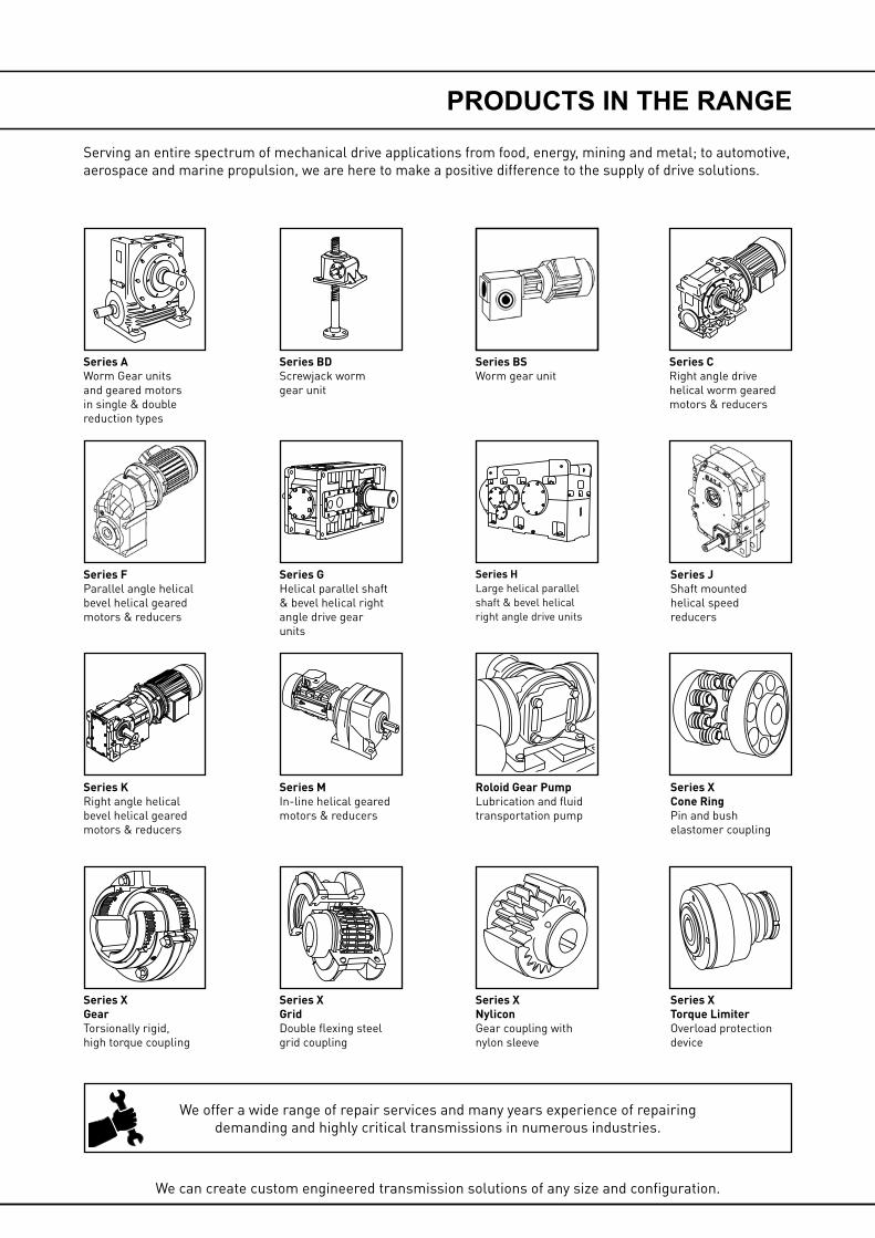
Serving an entire spectrum of mechanical drive applications from food, energy, mining and metal; to automotive, aerospace and marine propulsion, we are here to make a positive difference to the supply of drive solutions.
We offer a wide range of repair services and many years experience of repairing demanding and highly critical transmissions in numerous industries.
Series XCone RingPin and bush elastomer coupling
Series XTorque LimiterOverload protection device
Series JShaft mounted helical speed reducers
Series CRight angle drive helical worm geared motors & reducers
Series BDScrewjack wormgear unit
Series GHelical parallel shaft & bevel helical right angle drive gear units
Series XGridDouble flexing steel grid coupling
Series MIn-line helical geared motors & reducers
Series HLarge helical parallel shaft & bevel helical right angle drive units
Roloid Gear PumpLubrication and fluid transportation pump
Series BSWorm gear unit
Series XNyliconGear coupling with nylon sleeve
Series AWorm Gear units and geared motors in single & double reduction types
Series XGearTorsionally rigid,high torque coupling
Series KRight angle helical bevel helical geared motors & reducers
Series FParallel angle helical bevel helical geared motors & reducers
PRODUCTS IN THE RANGE
1
ELFLEX COUPLINGS
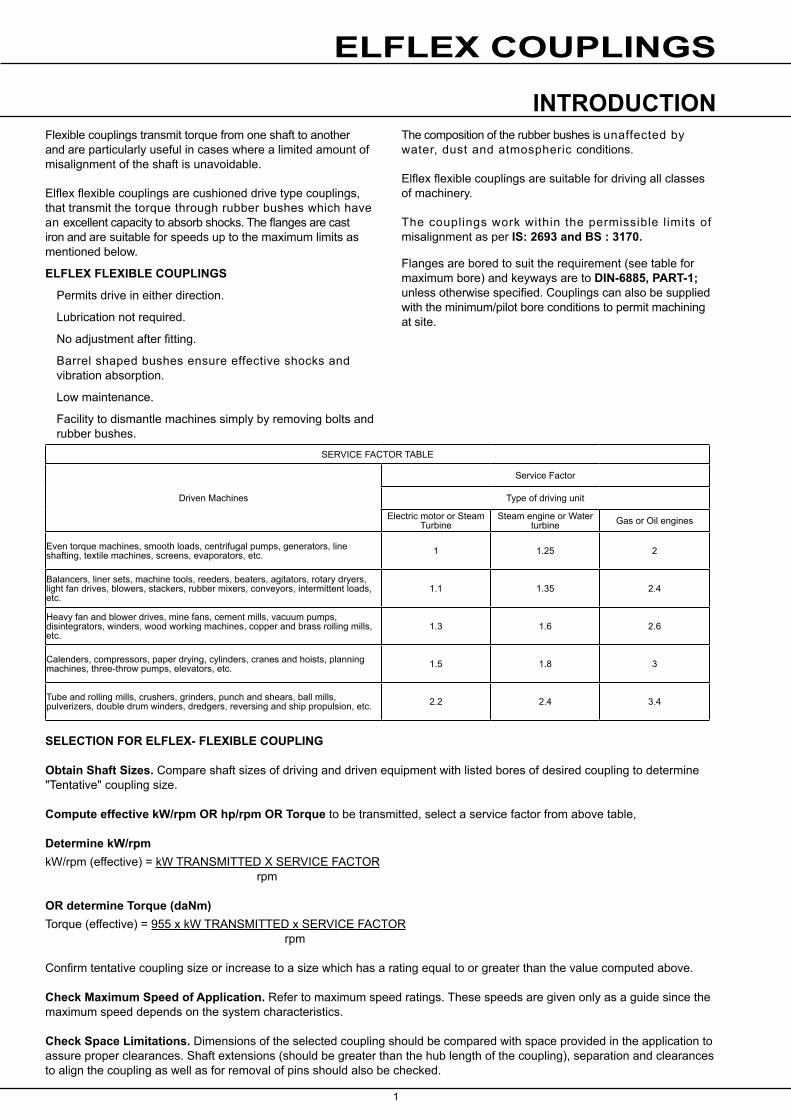
Flexible couplings transmit torque from one shaft to another and are particularly useful in cases where a limited amount of misalignment of the shaft is unavoidable.
Elflex flexible couplings are cushioned drive type couplings, that transmit the torque through rubber bushes which have an excellent capacity to absorb shocks. The flanges are cast iron and are suitable for speeds up to the maximum limits as mentioned below.
ELFLEX FLEXIBLE COUPLINGS
Permits drive in either direction.
Lubrication not required.
No adjustment after fitting.
Barrel shaped bushes ensure effective shocks and vibration absorption.
Low maintenance.
Facility to dismantle machines simply by removing bolts and rubber bushes.
The composition of the rubber bushes is unaffected by water, dust and atmospheric conditions.
Elflex flexible couplings are suitable for driving all classes of machinery.
The couplings work within the permissible limits of misalignment as per IS: 2693 and BS : 3170.
Flanges are bored to suit the requirement (see table for maximum bore) and keyways are to DIN-6885, PART-1; unless otherwise specified. Couplings can also be supplied with the minimum/pilot bore conditions to permit machining at site.
SERVICE FACTOR TABLE
Driven Machines
Service Factor
Type of driving unit
Electric motor or Steam Turbine
Steam engine or Water turbine Gas or Oil engines
Even torque machines, smooth loads, centrifugal pumps, generators, line shafting, textile machines, screens, evaporators, etc. 1 1.25 2
Balancers, liner sets, machine tools, reeders, beaters, agitators, rotary dryers, light fan drives, blowers, stackers, rubber mixers, conveyors, intermittent loads, etc.
1.1 1.35 2.4
Heavy fan and blower drives, mine fans, cement mills, vacuum pumps, disintegrators, winders, wood working machines, copper and brass rolling mills, etc.
1.3 1.6 2.6
Calenders, compressors, paper drying, cylinders, cranes and hoists, planning machines, three-throw pumps, elevators, etc. 1.5 1.8 3
Tube and rolling mills, crushers, grinders, punch and shears, ball mills, pulverizers, double drum winders, dredgers, reversing and ship propulsion, etc. 2.2 2.4 3.4
SELECTION FOR ELFLEX- FLEXIBLE COUPLING
Obtain Shaft Sizes. Compare shaft sizes of driving and driven equipment with listed bores of desired coupling to determine "Tentative" coupling size.
Compute effective kW/rpm OR hp/rpm OR Torque to be transmitted, select a service factor from above table,
Determine kW/rpmkW/rpm (effective) = kW TRANSMITTED X SERVICE FACTOR rpm
OR determine Torque (daNm)Torque (effective) = 955 x kW TRANSMITTED x SERVICE FACTOR rpm
Confirm tentative coupling size or increase to a size which has a rating equal to or greater than the value computed above.
Check Maximum Speed of Application. Refer to maximum speed ratings. These speeds are given only as a guide since the maximum speed depends on the system characteristics.
Check Space Limitations. Dimensions of the selected coupling should be compared with space provided in the application to assure proper clearances. Shaft extensions (should be greater than the hub length of the coupling), separation and clearances to align the coupling as well as for removal of pins should also be checked.
INTRODUCTION
1 2
EFC-01 0.007 7 12 16 32 28 85 48 42 32 3 50 4 1.5 0.004 7860
EFC-02 0.01 10.8 12 16 38 32 105 60 48 38 3 52 4 2.5 0.01 6360
EFC-03 0.022 21 12 16 42 40 112 63 60 42 3 52 5 3 0.014 5960
EFC-04 0.034 33 16 20 48 45 127 72 63 48 3 64 6 4.75 0.028 5260
EFC-05 0.056 53 16 20 55 50 144 82 75 55 3 64 8 7 0.048 4635
EFC-06 0.066 63.5 16 20 60 55 162 90 82 60 3 74 6 9.5 0.087 4120
EFC-07 0.091 87 16 20 70 65 180 105 98 70 3 74 8 12 0.143 3710
EFC-08 0.171 164 16 20 85 75 220 127 112 85 5 100 6 24 0.413 3035
EFC-09 0.214 205 16 20 95 85 240 140 128 95 5 100 8 31 0.612 2780
EFC-10 0.321 306 40 45 105 100 270 157 150 105 5 100 10 40 1.03 2475
EFC-11 0.383 365 40 45 110 105 285 162 155 110 5 126 8 50 1.54 2345
EFC-12 0.476 455 40 45 120 115 320 182 170 125 5 126 10 70 2.51 2085
EFC-13 0.638 609 40 45 130 125 340 196 185 140 6 152 8 92 3.9 1965
EFC-14 0.933 891 40 45 140 135 360 205 200 150 6 152 10 110 5 1855
EFC-15 1.262 1204 55 60 160 160 410 235 235 170 6 152 12 153 8.9 1630
EFC-16 1.948 1859 55 60 175 175 450 255 255 185 6 187 8 210 15.2 1480
EFC-17 2.835 2706 55 60 195 195 500 290 290 205 6 187 10 280 24.5 1335
ELFLEX COUPLINGS
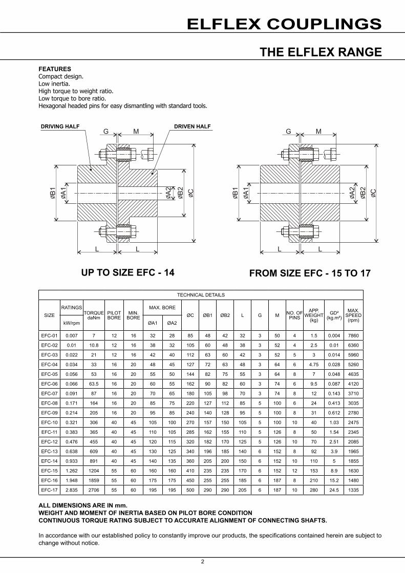
FEATURESCompact design.Low inertia.High torque to weight ratio.Low torque to bore ratio.Hexagonal headed pins for easy dismantling with standard tools.
TECHNICAL DETAILS
SIZERATINGS
TORQUE daNm
PILOT BORE
MIN. BORE
MAX. BOREØC ØB1 ØB2 L G M NO. OF
PINSAPP.
WEIGHT (kg)
GD² (kg.m²)
MAX.SPEED (rpm)kW/rpm ØA1 ØA2
ALL DIMENSIONS ARE IN mm.WEIGHT AND MOMENT OF INERTIA BASED ON PILOT BORE CONDITIONCONTINUOUS TORQUE RATING SUBJECT TO ACCURATE ALIGNMENT OF CONNECTING SHAFTS.
In accordance with our established policy to constantly improve our products, the specifications contained herein are subject to change without notice.
THE ELFLEX RANGE
DRIVING HALF DRIVEN HALF
UP TO SIZE EFC - 14 FROM SIZE EFC - 15 TO 17
3
FC 630 3.35 3200 120 220 360 630 260 120 110 12+5 14 410 66 1050
FC 710 4.7 4500 120 240 390 710 280 135 130 12+5 18 560 114 940
FC 800 6.35 6100 120 260 430 800 300 135 130 12+5 18 750 187 850
FC 900 8.95 8600 140 290 480 900 320 152 150 12+5 12 990 308 750
FC 1000 12.68 12200 180 320 540 1000 350 152 150 14+6 16 1300 474 670
FC 1120 17.16 16500 230 350 590 1120 380 170 170 14+6 16 1700 824 600
FC 1250 23.88 23000 240 380 640 1250 420 170 170 14+6 20 2150 1272 530
FC 1400 33.58 32000 360 420 720 1400 460 195 190 14+6 14 3050 2213 480
FC 1600 44.77 43000 280 460 750 1600 500 195 190 14+6 20 3950 4163 430
ELFLEX COUPLINGS
TECHNICAL DETAILS
SIZERATINGS
TORQUE daNm
BORE (ØA)ØB ØC L E M G NO. OF
PINSAPP.
WEIGHT (kg)
GD² (kg.m²)
MAX.SPEED (rpm)kW/rpm Min Max
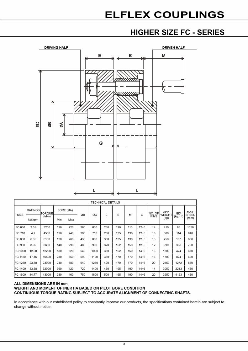
ALL DIMENSIONS ARE IN mm.WEIGHT AND MOMENT OF INERTIA BASED ON PILOT BORE CONDITIONCONTINUOUS TORQUE RATING SUBJECT TO ACCURATE ALIGNMENT OF CONNECTING SHAFTS.
In accordance with our established policy to constantly improve our products, the specifications contained herein are subject to change without notice.
HIGHER SIZE FC - SERIES
DRIVING HALF DRIVEN HALF
3 4
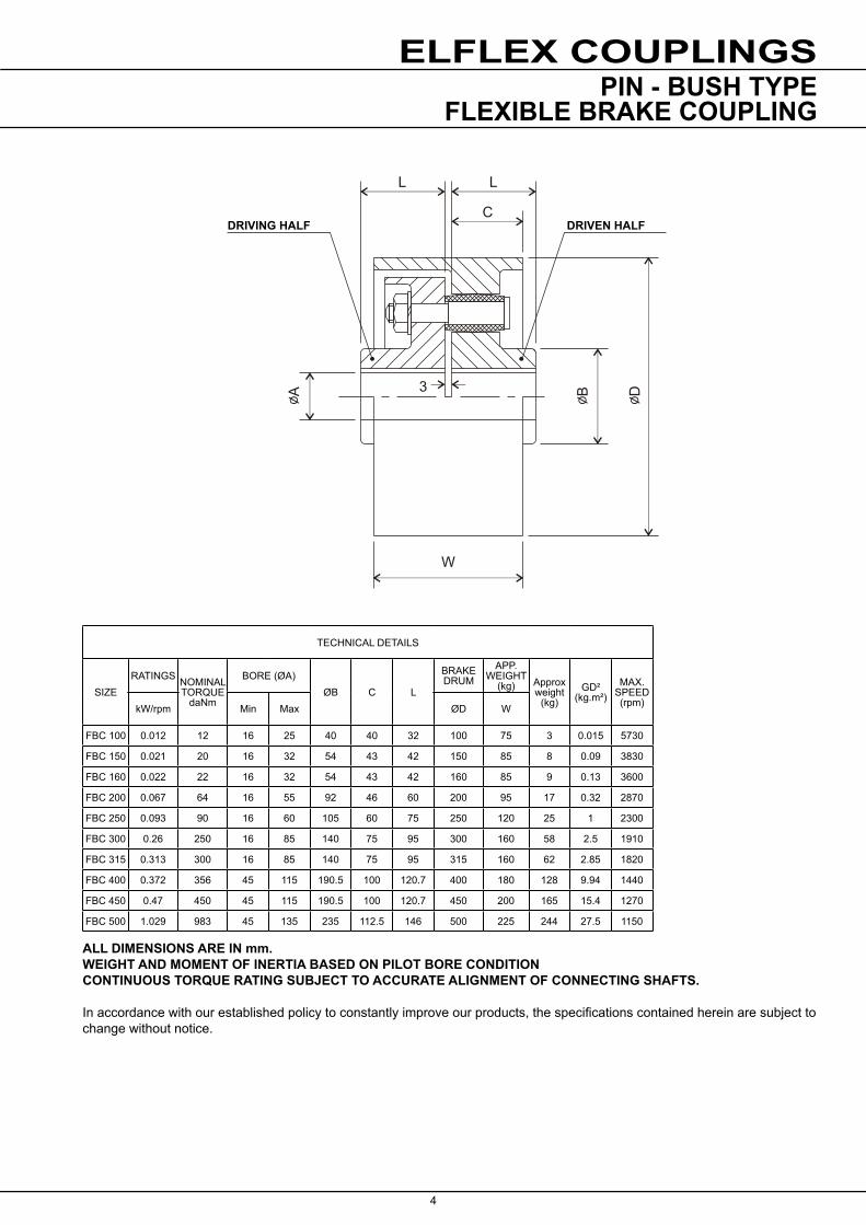
FBC 100 0.012 12 16 25 40 40 32 100 75 3 0.015 5730
FBC 150 0.021 20 16 32 54 43 42 150 85 8 0.09 3830
FBC 160 0.022 22 16 32 54 43 42 160 85 9 0.13 3600
FBC 200 0.067 64 16 55 92 46 60 200 95 17 0.32 2870
FBC 250 0.093 90 16 60 105 60 75 250 120 25 1 2300
FBC 300 0.26 250 16 85 140 75 95 300 160 58 2.5 1910
FBC 315 0.313 300 16 85 140 75 95 315 160 62 2.85 1820
FBC 400 0.372 356 45 115 190.5 100 120.7 400 180 128 9.94 1440
FBC 450 0.47 450 45 115 190.5 100 120.7 450 200 165 15.4 1270
FBC 500 1.029 983 45 135 235 112.5 146 500 225 244 27.5 1150
ELFLEX COUPLINGS
TECHNICAL DETAILS
SIZERATINGS NOMINAL
TORQUE daNm
BORE (ØA)ØB C L
BRAKE DRUM
APP. WEIGHT
(kg) Approx weight
(kg)GD²
(kg.m²)MAX.
SPEED (rpm)kW/rpm Min Max ØD W
ALL DIMENSIONS ARE IN mm.WEIGHT AND MOMENT OF INERTIA BASED ON PILOT BORE CONDITIONCONTINUOUS TORQUE RATING SUBJECT TO ACCURATE ALIGNMENT OF CONNECTING SHAFTS.
In accordance with our established policy to constantly improve our products, the specifications contained herein are subject to change without notice.
PIN - BUSH TYPEFLEXIBLE BRAKE COUPLING
DRIVING HALF DRIVEN HALF
TechnicalUp to - 100kW / 8500 Nm
Worm GearsCAM-1.00GB0111
www.benzlers.com
www.radicon.com
AUSTRALIA
Radicon Transmission (Australia) PTY Ltd Australia
Tel: +61 488 054 028
EUROPE
Benzler TBA BVJachthavenweg 2 NL-5928 NT Venlo
AustriaTel: +43 7 229 618 91Fax: +43 7 229 618 84
FranceTel: +33 687 718 711Fax: +31 77 324 59 01 GermanyTel: 0800 350 40 00Fax: 0800 350 40 01
ItalyTel: +39 02 824 3511
Netherlands & the rest of EuropeTel: +31 77 324 59 00Fax: +31 77 324 59 01
CONTACT US
DENMARK
Benzler Transmission A/SFuglebævej 3DDK-2770 Kastrup, Denmark
Tel: +45 36 34 03 00Fax: +45 36 77 02 42
FINLAND
Oy Benzler ABVanha Talvitie 3CFI-00580 Helsingfors, Finland
Tel: +358 9 340 1716Fax: +358 10 296 2072
INDIA
Elecon. Engineering Company Ltd.Anand Sojitra RoadVallabh Vidyanagar388120 GujaratIndia
Tel: +91 2692 236513Fax: +91 2692 227484
SWEDEN & NORWAY
AB BenzlersBox 922 (Landskronavägen 1)251 09 HelsingborgSweden
Tel: +46 42 18 68 00Fax: +46 42 21 88 03
THAILAND
Radicon Transmission (Thailand) Ltd700/43 Moo 6Amata Nakorn Industrial EstateTumbol KlongtumruMuang, Chonburi 20000Thailand
Tel: +66 3845 9044Fax: +66 3821 3655
UNITED KINGDOM
Radicon Transmission UK LtdUnit J3Lowfields Business Park, Lowfields Way, EllandWest Yorkshire, HX5 9DA
Tel: +44 (0) 1484 465 800 Fax: +44 (0) 1484 465 801
USA
Radicon USA Transmission Ltd1599 Lunt Avenue Elk Grove VillageChicagoIllinois60007USA
Tel: +1 847 593 9910Fax: +1 847 593 9950
TechnicalUp to - 100kW / 8500 Nm
Worm GearsCAM-1.00GB0111
Benzlers
Denmark +45 36 34 03 00Finland +358 9 340 1716Germany +49 800-350 4000 Italy +39 02 824 3511Sweden +46 42 186800The Netherlands +31 77 324 59 00www.benzlers.com
Radicon
Thailand +66 3845 9044 United Kingdom +44 (0) 1484 465 800USA +1 847 593 9910www.radicon.com