Embed Size (px)
Citation preview

NANO EXPRESS Open Access
Electrospinning onto Insulating Substratesby Controlling Surface Wettability andHumidityWooSeok Choi1, Geon Hwee Kim2, Jung Hwal Shin3, Geunbae Lim2 and Taechang An4*
Abstract
We report a simple method for electrospinning polymers onto flexible, insulating substrates by controlling thewettability of the substrate surface. Water molecules were adsorbed onto the surface of a hydrophilic polymersubstrate by increasing the local humidity around the substrate. The adsorbed water was used as the groundelectrode for electrospinning. The electrospun fibers were deposited only onto hydrophilic areas of the substrate,allowing for patterning through wettability control. Direct writing of polymer fiber was also possible through near-field electrospinning onto a hydrophilic surface.
Keywords: Electrospinning, Nanofibers, Surface wettability, Thin film water, Insulator substrate
BackgroundElectrospinning is a technique used to produce continu-ous fibers, with diameters of several hundred nanome-ters, using an electric field. Electrospinning is relativelyinexpensive and has been applied to a wide variety of ap-plications and materials [1–4]. The electrospinning setupconsists primarily of three parts: a high-voltage source, aspinneret, and a collector. The collector is generally aconductive substrate, such as a metal, that functions asthe ground electrode and helps form a stable electricfield in the spinneret. When non-conductive substratesare used as collectors, conductive ground electrodesmust be placed on the substrate surface [4, 5].Many industrial applications of electrospun nanofibers
require their deposition onto insulating substrates, such asflexible polymers [6, 7]. Cho et al. [6] demonstrated thedeposition of electrospun nanofibers onto thin, flexible in-sulator layers on an electrode. Electrospun nanofibers de-posited under such circumstances will follow or align withthe underlying electrodes. Min et al. [8] produced pat-terned organic semiconducting nanowires on a polymer
substrate using near-field electrospinning. In both cases,electrospinning onto the polymer substrate was only pos-sible if the insulating layer was thin enough (less than100 μm) to maintain a high electric field. Zheng et al. [7]reported electrospinning onto an insulating polymer sub-strate (polyethylene terephthalate) using an AC pulse-modulated electrohydrodynamic method. This method iscapable of electrospinning onto polymer substrates re-gardless of substrate thickness, but requires the applica-tion of a relatively complex AC electric field. While theaforementioned studies have demonstrated feasibility,electrospinning onto non-conductive surfaces has notattained widespread use in industrial applications.Here, we present a novel method for electrospinning
fibers onto insulating substrates that overcomes the limi-tations of previous work. Electrospinning has been dem-onstrated using a liquid electrolyte as the collectorelectrode [9–12]. Also note that, at an appropriately highhumidity, water molecules will adsorb to a hydrophilicsurface and begin to conduct electricity at approximatelyone monolayer [13]. If the proper humidity is main-tained around an insulating substrate with a hydrophilicsurface, then water molecules adsorbed on the surfacecan serve as an electrode layer, allowing the depositionof electrospun fibers. Unlike previous studies, thismethod is independent of substrate thickness because itrelies only on the surface characteristics of the substrate
* Correspondence: [email protected] of Mechanical Design Engineering, Andong National University,Kyungbuk 760-749, Republic of KoreaFull list of author information is available at the end of the article
© The Author(s). 2017 Open Access This article is distributed under the terms of the Creative Commons Attribution 4.0International License (http://creativecommons.org/licenses/by/4.0/), which permits unrestricted use, distribution, andreproduction in any medium, provided you give appropriate credit to the original author(s) and the source, provide a link tothe Creative Commons license, and indicate if changes were made.
Choi et al. Nanoscale Research Letters (2017) 12:610 DOI 10.1186/s11671-017-2380-6

in the surrounding environment. Moreover, it is compat-ible with conventional electrospinning techniques, re-quiring only humidity control.
MethodsPreparation of Polymer Substrate with a HydrophilicIn this experiment, a 500-μm acrylic substrate with anoriginally hydrophobic surface was used as the collector.Oxygen plasma treatment (CUTE, Femto Science,Korea) for 30 s of the acrylic substrate resulted in ahydrophilic surface populated with silanol groups(SiOH) [14]. This reaction was confirmed by a change inwater contact angle from 81.3° on pristine acrylic to36.7° after plasma treatment (Additional file 1: FigureS1b–d). Regions of the acrylic substrate were selectivelymade hydrophilic by applying a stencil mask prior toplasma treatment (Additional file 1: Figure S1a).
Preparations for ElectrospinningElectrospinning was performed at room temperatureand moderate humidity (relative humidity 40~50%)with 10 wt% polyurethane (PU) (Pellethane 2363-80AE; Lubrizol, USA) dissolved in a mixture (80/20,v/v) of tetrahydrofuran (THF) and dimethylformamide(DMF). To compare the effects of surface hydropho-bicity, an acrylic substrate with both hydrophilic andhydrophobic surfaces was placed on the ground elec-trode and used as a collector during electrospinning(Fig. 1a).
Local Humidity ControlTo increase the humidity in the immediate vicinity ofthe polymer substrate, a wet paper was placed betweenthe polymer substrate and the ground electrode (Fig. 1b).The humidity was relatively high only around the poly-mer substrate due to the low diffusivity of water vapor.
The humidity around the electrospinning syringe tipwas about 50%, while the humidity around the polymersubstrate was about 70% (Additional file 1: Figure S2).It has been shown that water molecule adsorption ontothe surface of hydrophilic polymers increases rapidlywhen the relative humidity exceeds 50% [15].
Results and DiscussionThe Force Acting on CNTs at the Liquid–Air InterfaceWe investigated two modes of electrospinning: a tip-to-electrode distance of 8 cm and applying 13 kVDC voltage with a fixed tip (far-field electrospinning),and a tip-to-electrode distance of 1 cm and applying2 kV DC voltage with a moving tip (near-fieldelectrospinning).Far-field electrospinning was performed by first pla-
cing the polymer substrate on the ground electrode.Electrospinning did not occur on hydrophobic areas ofthe substrate. Instead, the polymer solution would forma droplet at the end of the tip, eventually falling due togravity. In contrast, when the hydrophilized polymersubstrate was placed on the electrode, electrospun fi-bers were deposited on the substrate surface, as is ob-served with conventional electrospinning usingconductive substrates. Electrospun fibers were then de-posited onto a dual substrate having both hydrophobicand hydrophilic surfaces. Figure 2 shows digital cameraphotographs and micrographs of electrospun nanofi-bers on the dual substrate. Most of the fibers were de-posited on the hydrophilic surface. In Fig. 2a, b, theright and left halves of the polymer surface are hydro-philic and hydrophobic, respectively. The syringe tipwas fixed at the center of the substrate. Water vaporfrom the air had adsorbed only on the hydrophilic sur-face, acting as an electrode. An electric field wasformed between the tip and the water when a high
Fig. 1 Schematic diagram showing (a) the electrospinning process on a polymer substrate with local humidity control, and (b) is details ofboundary region of (a)
Choi et al. Nanoscale Research Letters (2017) 12:610 Page 2 of 7

voltage was applied for electrospinning. In contrast, thehydrophobic surface of the pristine acrylic substrateprevented the formation of an electric field between thetip and ground electrode. Electrospinning is aphenomenon in which a charged solution exits a syr-inge tip via a repulsive electrostatic force. The dropletof polymer solution that exits the jet is thereforecharged. The charged polymer solution experiences theelectrostatic force and moves toward the hydrophilicsurface. For the same reason, electrospinning did notoccur on the hydrophobic region of the electrode. Theelectrospun fibers deposited at the edge of the hydro-phobic domain in Fig. 2a are presumed to be due to theinfluence of the electrode exposed to the outside of thepolymer substrate. In Fig. 2c, d, five parallel bars ofpolymer substrate and the rest were hydrophobic andhydrophilic, respectively. The width and spacing of thebars were 2 mm. Electrospun fibers deposited on thehydrophobic surface were aligned with their longitu-dinal axes oriented perpendicular to the boundary ofhydrophilic and hydrophobic surfaces. But the
electrospun fibers on the hydrophilic surface were ran-domly disordered. This is consistent with well-knownresults in conventional electrospinning based on metalelectrodes [16].In order to verify the versatility, electrospinning was
carried out for four kinds of polymers: PCL (polycapro-lactone), PS (polystyrene), CA (cellulose acetate), andPVDF (polyvinylidene fluoride). PCL (15 wt%, Sigma-Aldrich) was dissolved in a mixture (20/80, v/v) of THFand DMF, PS (10 wt%, Sigma-Aldrich) was dissolved in amixture (80/20, v/v) of THF and DMF, CA (10 wt%,Sigma-Aldrich) was dissolved in a mixture (1/1, v/v) ofacetone and dimethylacetamide (DMAc), and PVDF(15 wt%, Sigma-Aldrich) was dissolved in DMF at 60 °C,respectively. In Fig. 3, four different electrospun fibersare deposited on the surface of hydrophilic surface likePU electrospun fibers.The morphology of the electrospun fiber on the poly-
mer substrate was compared with the conventional elec-trospinning and fiber on the metal electrode with locallyhumidity control. Figure 4 shows the SEM image of PU
Fig. 2 Images of far-field electrospun films on surfaces with different wettabilities. a, c Digital camera photographs. b, d Digital micrographs ofthe boundary region of a and c, respectively
Choi et al. Nanoscale Research Letters (2017) 12:610 Page 3 of 7
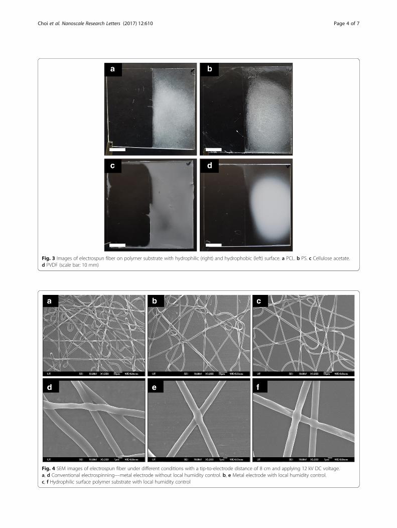
Fig. 3 Images of electrospun fiber on polymer substrate with hydrophilic (right) and hydrophobic (left) surface. a PCL. b PS. c Cellulose acetate.d PVDF (scale bar: 10 mm)
Fig. 4 SEM images of electrospun fiber under different conditions with a tip-to-electrode distance of 8 cm and applying 12 kV DC voltage.a, d Conventional electrospinning—metal electrode without local humidity control. b, e Metal electrode with local humidity control.c, f Hydrophilic surface polymer substrate with local humidity control
Choi et al. Nanoscale Research Letters (2017) 12:610 Page 4 of 7

electrospun fiber onto metal electrode with and withoutlocally humidity control and polymer substrate with lo-cally humidity control. The morphology of electrospunfibers was similar in all three cases. It is presumed thatstrong volatile solvents evaporate sufficiently becausehumidity maintains low around the syringe.The intensity of the electric field is one of the important
factors for altering the pattern of the electrospun fibers.Figure 5 shows the pattern of electrospun fiber onto apolymer substrate with hydrophilic (right) and hydropho-bic (left) surface where applied voltage was changed from6 to 16 kV at a tip-to-electrode distance of 8 cm. It isknown that as the electric field increases, the loops ofpolymer jet become larger as the bending instability in-creases [17, 18]. As the loops of polymer jet grow, electro-spun fibers deposit on the electrode exposed to theoutside of the polymer substrate. Therefore, electrospunfibers deposit on the hydrophobic surface of polymer sub-strate between the electrode and the hydrophilic surface.On the other hand, when the loops of polymer jet aresmall, most of the electrospun fibers deposit on the hydro-philic surface of the polymer substrate located verticallybelow the syringe tip.Near-field electrospinning was performed at a tip-to-
substrate distance of 1 cm and the tip was moved at a rateof 100 mm/s. Figure 6a, b compares direct-patterned poly-mer nanofibers on a conductive electrode and a hydrophilicpolymer substrate. When presented with a hydrophobic re-gion on the electrode, fibers were emitted toward the ex-posed electrode. Conversely, fibers were emitted directly
toward the hydrophilized polymer substrate. Charges in adroplet of polymer solution are unable to escape if thedroplet falls onto an insulating surface. Thus, the charge ofthis initially deposited polymer layer will repel incomingelectrospun droplets [19]. Figure 6c, d shows the result ofpolymer fibers being written directly onto a polymer sub-strate having both hydrophobic and hydrophilic surfaces.The vertical line in the image is the border between thehydrophilic (left) and hydrophobic (right) regions. Fiberson the hydrophilic surface were drawn along the tip pathin a straight line and were similar in form to fibers madevia conventional near-field electrospinning. In contrast, fi-bers on the hydrophobic surface were unstable and exhib-ited twisted or curved shapes. Fibers on the hydrophilicsurface were placed by inertia resulting from the movingtip, as it moved from the hydrophilic region. Polymer fibersfalling in such a way were highly unstable due to the lackof an electric field on the hydrophobic surface. Figure 6eshows fibers resulting from the direct writing of polymerlines onto the hydrophilic polymer substrate. Note thatFig. 6f is an enlargement of Fig. 6e. These data confirm thatpolymer patterns can be drawn directly onto the surface ofan insulator with a hydrophilic surface as they would bedrawn on an electrode surface.
ConclusionsWe introduced a novel method for electrospinning ontoan insulating substrate regardless of substrate thickness.Plasma treatment of an acrylic substrate produces a hydro-philic surface. In an appropriately high-humidity
Fig. 5 Images of PU electrospun fiber on polymer substrate with hydrophilic (right) and hydrophobic (left) surface according to applied DCvoltage for 2 min. a 6 kV. b 8 kV. c 10 kV. d 12 kV. e 14 kV. f 16 kV (scale bar: 10 mm)
Choi et al. Nanoscale Research Letters (2017) 12:610 Page 5 of 7

environment, water molecules adsorb to form a thin layerthat acts as a ground electrode. Electrospun nanofiberswere deposited on a flexible polymer substrate using thismethod and there was no significant difference from themorphology of electrospun fiber from conventional elec-trospinning. It was also shown that polymer fibers could bewritten directly on hydrophilic surfaces of hydrophobicsubstrates using near-field electrospinning. Increasing thelocal humidity around the polymer substrate enabled elec-trospinning onto the insulator surface. This interestingresult contrasts with the general assumption that electro-spinning should be performed at low humidity. Specific re-gions of a polymer substrate can be defined forelectrospun fiber deposition by selectively controlling thewettability of the substrate. Therefore, fiber patterns arepossible without the relatively complex and expensiveprocesses, such as microelectromechanical system(MEMS)-based techniques, currently used to fabricatemicropatterned electrodes. Moreover, we believe that elec-trospinning using conductive materials such as carbon
nanotubes or conducting polymers may be applicable tofabricating electrodes on flexible substrates that can beused in wearable devices.
Additional file
Additional file 1: Figure S1. (a) Schematic diagram shows theelectrospinning process and selective oxygen plasma treatment. Contactangles were measured on a (b) pristine polymer substrate and (c) polymersubstrate following oxygen plasma treatment. (d) A graph of plasmatreatment time versus contact angle of polymer substrate. Figure S2.Relative humidity near the polymer substrate and syringe tip. (DOC 464 kb)
AcknowledgementsThis work was supported by Korea National University of Transportation in2016 and National Research Foundation of Korea (NRF) grants funded by theKorean Government (MSIP) (NO. 2015R1A2A2A01006496).
Authors’ ContributionsWC, GHK, and TA conceived of the study and participated in its design. GHKand TA participated in the fabrication of selective hydrophobic surface. WCand TA carried out electrospinning experiments. WC, JHS, and GB wrote thismanuscript. All authors read and approved the final manuscript.
Fig. 6 Images of near-field electrospun films on a a hydrophobic surface and b a hydrophilic surface. Images of polymer fibers written directly onto apolymer substrate with a hydrophobic surface (left) and a hydrophilic surface (right); c a digital camera photograph and d a digital micrograph. Imagesof electrospun polymer fibers written directly on a hydrophilic surface; e a digital camera photograph and f a digital micrograph
Choi et al. Nanoscale Research Letters (2017) 12:610 Page 6 of 7
Competing InterestsThe authors declare that they have no competing interests.
Publisher’s NoteSpringer Nature remains neutral with regard to jurisdictional claims inpublished maps and institutional affiliations.
Author details1Department of Mechanical Engineering, Korea National University ofTransportation, Chungju, Chungcheongbuk-do 380-702, Republic of Korea.2Department of Mechanical Engineering, Pohang University of Science andTechnology (POSTECH), Pohang 790-784, Republic of Korea. 3BiomedicalEngineering, School of Life Sciences, Ulsan National Institute of Science andTechnology (UNIST), 50, UNIST-gil, Ulsan 44919, Republic of Korea.4Department of Mechanical Design Engineering, Andong National University,Kyungbuk 760-749, Republic of Korea.
Received: 4 July 2017 Accepted: 21 November 2017
References1. Huang Z-M, Zhang Y-Z, Kotaki M, Ramakrishna S (2003) A review on
polymer nanofibers by electrospinning and their applications innanocomposites. Compos Sci Technol 63:2223–2253
2. Teo WE, Ramakrishna S (2006) A review on electrospinning design andnanofibre assemblies. Nanotechnology 17:R89–R106
3. Zhang C-L, Yu S-H (2014) Nanoparticles meet electrospinning: recentadvances and future prospects. Chem Soc Rev 43:4423–4448
4. Mirjalili M, Zohoori S (2016) Review for application of electrospinning andelectrospun nanofibers technology in textile industry. J Nanostruct Chem 6:207–213
5. Ramakrishna S, Fujihara K, Teo WE, Lim TC & Zuwei Ma: An introduction toElectrospinning and Nanofibers. (World Scientific Publishing Company, 2005)
6. Cho SJ, Kim B, An T, Lim G (2010) Replicable multilayered nanofibrouspatterns on a flexible film. Langmuir 26:14395–14399
7. Zheng J-Y et al (2014) Electrohydrodynamic direct-write orderly micro/nanofibrous structure on flexible insulating substrate. J Nanomater:1–7
8. Min S-Y et al (2013) Large-scale organic nanowire lithography andelectronics. Nat Commun 4:1773
9. Heo J et al (2016) Enhanced cellular distribution and infiltration in a wetelectrospun three-dimensional fibrous scaffold using eccentric rotation-based hydrodynamic conditions. Sensors Actuators B Chem 226:357–363
10. Smit E, Bűttner U, Sanderson RD (2005) Continuous yarns from electrospunfibers. Polymer 46:2419–2423
11. Yokoyama Y et al (2009) Novel wet electrospinning system for fabrication ofspongiform nanofiber 3-dimensional fabric. Mater Lett 63:754–756
12. Park SM, Kim DS (2015) Electrolyte-assisted electrospinning for a self-assembled, free-standing nanofiber membrane on a curved surface.Adv Mater 27:1682–1687
13. Beaglehole D (1997) Aspects of vapor adsorption on solids. Physica A:Statistical Mechanics and its Applications 244:40–44
14. Johnston EE, Ratner BD (1996) Surface characterization of plasma depositedorganic thin films. J Electron Spectrosc Relat Phenom 81:303–317
15. Vogt BD, Soles CL, Lee H-J, Lin EK, Wu W (2005) Moisture absorption intoultrathin hydrophilic polymer films on different substrate surfaces. Polymer46:1635–1642
16. Li D, Wang Y, Xia Y (2003) Electrospinning of polymeric and ceramicnanofibers as uniaxially aligned arrays. Nano Lett 3:1167–1171
17. Reneker DH, Yarin AL, Fong H, Koombhongse S (2000) Bending instabilityof electrically charged liquid jets of polymer solutions in electrospinning.J Appl Phys 87:4531–4547
18. Lauricella M, Cipolletta F, Pontrelli G, Pisignano D, Succi S (2017) Effects oforthogonal rotating electric fields on electrospinning process. Phys Fluids29:082003
19. Wang H, Zheng G, Li W, Wang X, Sun D (2011) Direct-writing organic three-dimensional nanofibrous structure. Appl Phys A Mater Sci Process 102:457–461
Choi et al. Nanoscale Research Letters (2017) 12:610 Page 7 of 7