Embed Size (px)
Citation preview

ANSI/BICSI 005-2016 Electronic Safety and Security (ESS) System Design and Implementation
Best Practices
Committee Approval: April 2016
First Published: May 2016
DEMONSTRATION VERSION ONLY – NOT FOR RESALE

i
BICSI International Standards BICSI international standards contain information deemed to be of technical value to the industry and are published at the request of the originating committee. The BICSI International Standards Program subjects all of its draft standards to a rigorous public review and comment resolution process, which is a part of the full development and approval process for any BICSI international standard. The BICSI International Standards Program reviews its standards at regular intervals. By the end of the fifth year after a standard’s publication, the standard will be reaffirmed, rescinded, or revised according to the submitted updates and comments from all interested parties. Suggestions for revision should be directed to the BICSI International Standards Program, care of BICSI.
Copyright This BICSI document is a standard and is copyright protected. Except as permitted under the applicable laws of the user's country, neither this BICSI standard nor any extract from it may be reproduced, stored in a retrieval system or transmitted in any form or by any means, electronic, photocopying, recording, or otherwise, without prior written permission from BICSI being secured. Requests for permission to reproduce this document should be addressed to BICSI. Reproduction may be subject to royalty payments or a licensing agreement. Violators may be prosecuted.
Published by:
BICSI 8610 Hidden River Parkway Tampa, FL 33637-1000 USA
Copyright © 2015 BICSI
All rights reserved Printed in U.S.A.
DEMONSTRATION VERSION ONLY – NOT FOR RESALE

ANSI/BICSI 005-2016
ii
Notice of Disclaimer and Limitation of Liability BICSI standards and publications are designed to serve the public interest by offering information communication and technology systems design guidelines and best practices. Existence of such standards and publications shall not in any respect preclude any member or nonmember of BICSI from manufacturing or selling products not conforming to such standards and publications, nor shall the existence of such standards and publications preclude their voluntary use, whether the standard is to be used either domestically or internationally. By publication of this standard, BICSI takes no position respecting the validity of any patent rights or copyrights asserted in connection with any item mentioned in this standard. Additionally, BICSI does not assume any liability to any patent owner, nor does it assume any obligation whatever to parties adopting the standard or publication. Users of this standard are expressly advised that determination of any such patent rights or copyrights, and the risk of infringement of such rights, are entirely their own responsibility. This standard does not purport to address all safety issues or applicable regulatory requirements associated with its use. It is the responsibility of the user of this standard to review any existing codes and other regulations recognized by the national, regional, local, and other recognized authorities having jurisdiction (AHJ) in conjunction with the use of this standard. Where differences occur, those items listed within the codes or regulations of the AHJ supersede any requirement or recommendation of this standard. All warranties, express or implied, are disclaimed, including without limitation, any and all warranties concerning the accuracy of the contents, its fitness or appropriateness for a particular purpose or use, its merchantability and its non-infringement of any third party’s intellectual property rights. BICSI expressly disclaims any and all responsibilities for the accuracy of the contents and makes no representations or warranties regarding the content’s compliance with any applicable statute, rule, or regulation. BICSI shall not be liable for any and all damages, direct or indirect, arising from or relating to any use of the contents contained herein, including without limitation any and all indirect, special, incidental, or consequential damages (including damages for loss of business, loss of profits, litigation, or the like), whether based upon breach of contract, breach of warranty, tort (including negligence), product liability or otherwise, even if advised of the possibility of such damages. The foregoing negation of damages is a fundamental element of the use of the contents hereof, and these contents would not be published by BICSI without such limitations.
DEMONSTRATION VERSION ONLY – NOT FOR RESALE
Electronic Safety and Security (ESS) System Design and Implementation Best Practices
iii
TABLE OF CONTENTS
PREFACE ....................................................................................................................... xi
1 Introduction .................................................................................................................... 1 1.1 General ............................................................................................................................................................ 1 1.2 Purpose ............................................................................................................................................................ 1 1.3 Categories of Criteria ..................................................................................................................................... 1
2 Scope ........................................................................................................................... 2
3 Required Standards and Documents ............................................................................ 3
4 Definitions, Acronyms, Abbreviations, and Units of Measurement ............................ 5 4.1 Definitions ....................................................................................................................................................... 5 4.2 Acronyms and Abbreviations ........................................................................................................................ 9 4.3 Units of Measurement .................................................................................................................................. 10
5 Telecommunications Infrastructure ............................................................................ 11 5.1 Overview ....................................................................................................................................................... 11 5.2 Topology ........................................................................................................................................................ 11 5.2.1 Star Topology ........................................................................................................................................... 11 5.2.2 Non-Star Topologies ................................................................................................................................. 11 5.3 Spaces ............................................................................................................................................................ 12 5.3.1 Equipment Rooms .................................................................................................................................... 12 5.3.2 Telecommunications Rooms and Telecommunications Enclosures ......................................................... 14 5.4 Cabling .......................................................................................................................................................... 15 5.4.1 Backbone Cabling..................................................................................................................................... 15 5.4.2 Horizontal Cabling ................................................................................................................................... 15 5.4.3 Horizontal Connection Point (HCP) ......................................................................................................... 19 5.4.4 Power over Ethernet (PoE) ....................................................................................................................... 20 5.5 Cabling Pathways ......................................................................................................................................... 21 5.5.1 Requirements ............................................................................................................................................ 21 5.5.2 Enclosures, Pull Boxes and Splice Boxes ................................................................................................. 21 5.5.3 ESS Pathway Redundancy ........................................................................................................................ 21 5.5.4 ESS Pathways between Telecommunications Spaces within a Building .................................................. 21 5.5.5 ESS Campus Pathways Between Buildings .............................................................................................. 22 5.5.6 ESS Pathways Serving Equipment Outlets ............................................................................................... 22 5.5.7 ESS Pathway Separation from Power and EMI Sources .......................................................................... 22 5.5.8 ESS Pathway Bonding and Grounding ..................................................................................................... 23 5.5.9 Special Pathways and Spaces Considerations........................................................................................... 23 5.5.10 Secure Areas ............................................................................................................................................. 24 5.6 Telecommunications Outlet and Connectors ............................................................................................. 24 5.6.1 Overview .................................................................................................................................................. 24 5.6.2 Facility Connections by Modified Permanent Link Method .................................................................... 25 5.7 Cabling Installation Requirements ............................................................................................................. 26 5.7.1 Overview .................................................................................................................................................. 26 5.7.2 Bonding and Grounding Considerations ................................................................................................... 26 5.7.3 Transmission Performance Field Testing ................................................................................................. 26
DEMONSTRATION VERSION ONLY – NOT FOR RESALE
ANSI/BICSI 005-2016
iv
5.8 Administration and Documentation............................................................................................................ 28 5.8.1 Requirements ............................................................................................................................................ 28 5.8.2 Recommendations ..................................................................................................................................... 28 5.9 ESS Device Mounting Heights ..................................................................................................................... 28 5.9.1 Requirements ............................................................................................................................................ 28 5.9.2 Recommendations ..................................................................................................................................... 29 5.10 Infrastructure for Wireless Transmission .................................................................................................. 29 5.10.1 Requirements ............................................................................................................................................ 29 5.10.2 Additional Information ............................................................................................................................. 29 5.11 Coverage Area Planning and Density ......................................................................................................... 29 5.11.1 Introduction ............................................................................................................................................... 29 5.11.2 Recommendations ..................................................................................................................................... 29
6 Intrusion Detection Systems ....................................................................................... 31 6.1 Overview ........................................................................................................................................................ 31 6.2 Developing an IDS ........................................................................................................................................ 31 6.2.1 Requirements ............................................................................................................................................ 31 6.2.2 Recommendations ..................................................................................................................................... 31 6.3 System Connectivity ..................................................................................................................................... 31 6.3.1 Wired Devices ........................................................................................................................................... 31 6.3.2 Wireless Devices ....................................................................................................................................... 32 6.4 Sensors ........................................................................................................................................................... 32 6.4.1 Introduction ............................................................................................................................................... 32 6.4.2 Recommendations ..................................................................................................................................... 32 6.5 Notification .................................................................................................................................................... 32 6.5.1 Requirements ............................................................................................................................................ 32 6.5.2 Recommendations ..................................................................................................................................... 32 6.5.3 Additional Information ............................................................................................................................. 33 6.6 Control Panel ................................................................................................................................................ 33 6.6.1 Requirements ............................................................................................................................................ 33 6.6.2 Recommendations ..................................................................................................................................... 33 6.7 Keypads and Annunciators .......................................................................................................................... 34 6.7.1 Requirements ............................................................................................................................................ 34 6.7.2 Recommendations ..................................................................................................................................... 34 6.8 Initiating Devices .......................................................................................................................................... 34 6.8.1 Overview ................................................................................................................................................... 34 6.8.2 Motion Sensors ......................................................................................................................................... 34 6.8.3 Window Sensors ....................................................................................................................................... 34 6.8.4 Door Status Sensors .................................................................................................................................. 35 6.8.5 Perimeter Sensors ..................................................................................................................................... 35 6.9 Optional Integrated Equipment .................................................................................................................. 35 6.9.1 Introduction ............................................................................................................................................... 35 6.9.2 Requirements ............................................................................................................................................ 35
7 Video Surveillance ....................................................................................................... 37 7.1 Overview ........................................................................................................................................................ 37 7.2 Generation and Conformance with Use Cases ........................................................................................... 37 7.2.1 Scene Characteristics ................................................................................................................................ 37 7.2.2 Observation as a Primary VSS Function ................................................................................................... 38 7.2.3 Forensic Review as a Primary VSS Function ........................................................................................... 38 7.2.4 Recognition as a Primary VSS Function ................................................................................................... 39 7.2.5 Additional VSS Functions ........................................................................................................................ 39
DEMONSTRATION VERSION ONLY – NOT FOR RESALE

Electronic Safety and Security (ESS) System Design and Implementation Best Practices
v
7.3 Device Groups and Interoperability ........................................................................................................... 40 7.3.1 Requirements ............................................................................................................................................ 40 7.4 Device Categories ......................................................................................................................................... 40 7.4.1 Requirements ............................................................................................................................................ 40 7.5 Use Cases ....................................................................................................................................................... 41 7.5.1 Requirements ............................................................................................................................................ 41 7.6 Open Network Video Interface Forum Conformance .............................................................................. 41 7.6.1 Requirements ............................................................................................................................................ 41 7.7 Deployment Process ..................................................................................................................................... 41 7.7.1 Requirements ............................................................................................................................................ 41 7.7.2 Recommendations .................................................................................................................................... 42 7.8 Authentication of Network Video Cameras for Improved ESS Network Security ................................ 43 7.8.1 Requirements ............................................................................................................................................ 43
8 Access Control Systems .............................................................................................. 45 8.1 Overview ....................................................................................................................................................... 45 8.2 System Structure .......................................................................................................................................... 45 8.2.1 Overview .................................................................................................................................................. 45 8.2.2 Central Equipment Processing (Level 1) .................................................................................................. 45 8.2.3 Computer Hardware and Software ........................................................................................................... 45 8.2.4 Server ........................................................................................................................................................ 45 8.2.5 Software .................................................................................................................................................... 46 8.2.6 Backup ...................................................................................................................................................... 46 8.2.7 Event Recording ....................................................................................................................................... 46 8.2.8 Backup Power ........................................................................................................................................... 46 8.2.9 Access Control Workstation ..................................................................................................................... 46 8.2.10 Badging System ........................................................................................................................................ 47 8.2.11 Visitor Management ................................................................................................................................. 47 8.3 Controllers for Intelligent Field Processing (Level 2) ............................................................................... 47 8.3.1 Overview .................................................................................................................................................. 47 8.3.2 Controller Configurations ......................................................................................................................... 47 8.4 Peripheral Devices (Level 3) ........................................................................................................................ 48 8.4.1 Overview .................................................................................................................................................. 48 8.4.2 Relays ....................................................................................................................................................... 48 8.4.3 Power Distribution .................................................................................................................................... 48 8.4.4 Readers ..................................................................................................................................................... 49 8.4.5 Request to Exit Devices ............................................................................................................................ 49 8.4.6 Door Contacts ........................................................................................................................................... 49 8.4.7 Electrified Door Hardware ....................................................................................................................... 49 8.4.8 Fail-Secure/Fail-Safe/Fail Latched ........................................................................................................... 49 8.4.9 Power to Locks ......................................................................................................................................... 50 8.5 Credentials (Level 4) .................................................................................................................................... 51 8.5.1 Overview .................................................................................................................................................. 51 8.5.2 Web-Enabled Access Control ................................................................................................................... 51 8.5.3 IP Card Readers ........................................................................................................................................ 51 8.5.4 IP Controllers ............................................................................................................................................ 51 8.5.5 Communications ....................................................................................................................................... 51 8.5.6 Analog Communications .......................................................................................................................... 52 8.5.7 TCP/IP or Network Communications ....................................................................................................... 52
DEMONSTRATION VERSION ONLY – NOT FOR RESALE

ANSI/BICSI 005-2016
vi
9 Fire Alarm Systems ..................................................................................................... 53 9.1 Introduction .................................................................................................................................................. 53 9.1.1 Overview ................................................................................................................................................... 53 9.1.2 Recommendations ..................................................................................................................................... 54 9.2 Regulatory ..................................................................................................................................................... 54 9.2.1 Overview ................................................................................................................................................... 54 9.3 Risk Assessment ............................................................................................................................................ 54 9.3.1 Overview ................................................................................................................................................... 54 9.3.2 Requirements ............................................................................................................................................ 54 9.3.3 Recommendations ..................................................................................................................................... 55 9.4 Fire Alarm Systems ...................................................................................................................................... 55 9.4.1 Introduction ............................................................................................................................................... 55 9.4.2 Control Panel ............................................................................................................................................ 55 9.4.3 Detection/Initiation ................................................................................................................................... 56 9.4.4 Notification Appliances ............................................................................................................................ 56 9.5 Communications Systems ............................................................................................................................ 57 9.5.1 Overview ................................................................................................................................................... 57 9.5.2 Requirements ............................................................................................................................................ 57 9.5.3 Recommendations. .................................................................................................................................... 57 9.6 Pathways ........................................................................................................................................................ 58 9.6.1 Introduction ............................................................................................................................................... 58 9.6.2 Class N ...................................................................................................................................................... 58 9.6.3 Class N Cabling ........................................................................................................................................ 60 9.7 Circuits .......................................................................................................................................................... 60 9.7.1 Overview ................................................................................................................................................... 60 9.7.2 Requirements ............................................................................................................................................ 61 9.7.3 Recommendations ..................................................................................................................................... 61 9.8 Monitoring and Supervision ........................................................................................................................ 61 9.8.1 Overview ................................................................................................................................................... 61 9.8.2 Requirements ............................................................................................................................................ 62 9.8.3 Recommendations ..................................................................................................................................... 62 9.9 Power over Ethernet (PoE) Implementation .............................................................................................. 62 9.9.1 Overview ................................................................................................................................................... 62 9.9.2 Requirements ............................................................................................................................................ 62 9.9.3 Recommendations ..................................................................................................................................... 62 9.10 Class N Operations and Maintenance ......................................................................................................... 62 9.10.1 Overview ................................................................................................................................................... 62 9.10.2 Requirements ............................................................................................................................................ 62 9.10.3 Recommendations ..................................................................................................................................... 62 9.11 As-Built Drawings and Related Documentation ........................................................................................ 62 9.11.1 Overview ................................................................................................................................................... 62 9.11.2 Requirements ............................................................................................................................................ 62 9.11.3 Recommendations ..................................................................................................................................... 62
10 Integrated Systems ...................................................................................................... 63 10.1 Overview ........................................................................................................................................................ 63 10.2 ESS Integrated Services, Design and Integration ...................................................................................... 63 10.2.1 Public Network Services ........................................................................................................................... 63 10.2.2 Design and Selection of Components ....................................................................................................... 64 10.2.3 ESS Integration ......................................................................................................................................... 64
DEMONSTRATION VERSION ONLY – NOT FOR RESALE
Electronic Safety and Security (ESS) System Design and Implementation Best Practices
vii
10.3 ESS Components .......................................................................................................................................... 64 10.3.1 Overview .................................................................................................................................................. 64 10.3.2 Intrusion Detection System....................................................................................................................... 64 10.3.3 Access Control System ............................................................................................................................. 65 10.3.4 Video Surveillance System ....................................................................................................................... 65 10.3.5 Physical Security Information Management System ................................................................................ 65 10.3.6 Sensor-Based System ............................................................................................................................... 65 10.3.7 Building Automation System ................................................................................................................... 65 10.3.8 Location System ....................................................................................................................................... 65 10.3.9 Global Positioning System ....................................................................................................................... 67 10.3.10 Automated Infrastructure Management (AIM) with other ESS systems .................................................. 67 10.3.11 Software .................................................................................................................................................... 68 10.4 System Configuration and Expandability .................................................................................................. 69 10.4.1 Overview .................................................................................................................................................. 69 10.4.2 Input/Output Matrix .................................................................................................................................. 69 10.4.3 Maps and Icons ......................................................................................................................................... 69 10.4.4 System Response Times ........................................................................................................................... 70 10.4.5 System Expansion Capability ................................................................................................................... 70 10.5 ESS Integration Process ............................................................................................................................... 70 10.5.1 Overview .................................................................................................................................................. 70 10.5.2 Integration Process Team Members ......................................................................................................... 70 10.5.3 Integration Process ................................................................................................................................... 71
11 Risk Management and Risk Assessment.................................................................... 75 11.1 Introduction .................................................................................................................................................. 75 11.2 Requirements ................................................................................................................................................ 75 11.3 Additional Information ................................................................................................................................ 75
12 Commissioning ............................................................................................................ 77 12.1 Overview ....................................................................................................................................................... 77 12.2 Documentation .............................................................................................................................................. 77 12.2.1 Overview .................................................................................................................................................. 77 12.2.2 Requirements ............................................................................................................................................ 77 12.3 Cleaning ........................................................................................................................................................ 78 12.3.1 Overview .................................................................................................................................................. 78 12.3.2 Requirements ............................................................................................................................................ 78 12.3.3 Recommendations .................................................................................................................................... 78 12.4 Labeling Components .................................................................................................................................. 78 12.4.1 Requirements ............................................................................................................................................ 78 12.4.2 Recommendations .................................................................................................................................... 78 12.5 Testing ........................................................................................................................................................... 78 12.5.1 Acceptance Testing Plan........................................................................................................................... 78 12.5.2 System Testing ......................................................................................................................................... 78 12.5.3 Acceptance Testing ................................................................................................................................... 79 12.5.4 Retesting Equipment and Systems ............................................................................................................ 80 12.5.5 Warranty Periods ...................................................................................................................................... 80 12.6 Additional Commissioning Tasks ............................................................................................................... 80 12.7 Training ......................................................................................................................................................... 81
Appendix A Cabling Pathways (Normative) ...................................................................... 83 A.1 Overview ....................................................................................................................................................... 83 A.2 Types of Cabling Pathways ......................................................................................................................... 83 A.3 General Installation Practices ..................................................................................................................... 91
DEMONSTRATION VERSION ONLY – NOT FOR RESALE

ANSI/BICSI 005-2016
viii
Appendix B Electronic Safety and Security (ESS) Design Fundamentals (Informative) .. 92 B.1 Introduction .................................................................................................................................................. 93 B.2 Elements ........................................................................................................................................................ 93 B.3 Types of Projects ........................................................................................................................................... 94 B.4 Current and Future Trends in Safety and Security................................................................................... 94 B.5 Electronic Safety and Security System Development Basics..................................................................... 95
Appendix C Wireless Transmission (Informative) ............................................................ 97 C.1 Overview ........................................................................................................................................................ 97 C.2 Radio Frequency Transmission ................................................................................................................... 97 C.3 Free Space Optics ......................................................................................................................................... 97 C.4 Licensed Microwave Radio Transmission .................................................................................................. 98 C.5 Frequency Selection ...................................................................................................................................... 98
Appendix D Cloud Computing (Informative) ..................................................................... 99 D.1 Overview ........................................................................................................................................................ 99 D.2 Services .......................................................................................................................................................... 99 D.3 Infrastructure Management of Cloud Services ........................................................................................ 101 D.4 Selecting an Infrastructure Management Model ..................................................................................... 102 D.5 Cloud Deployment Models ......................................................................................................................... 103 D.6 Delivering Secure Services ......................................................................................................................... 103 D.7 Trends .......................................................................................................................................................... 104
Appendix E System Training (Informative) ..................................................................... 105 E.1 Overview ...................................................................................................................................................... 105 E.2 Sessions ........................................................................................................................................................ 105 E.3 Position or Task Training .......................................................................................................................... 105 E.4 Training Schedules ..................................................................................................................................... 107
Appendix F ESS Operations and Maintenance (Informative) ........................................ 109 F.1 Operation Best Practices ............................................................................................................................ 109 F.2 Maintenance Plan Recommendations ....................................................................................................... 110 F.3 Service Contracts ........................................................................................................................................ 110
Appendix G Related Documents (Informative) ............................................................... 113
DEMONSTRATION VERSION ONLY – NOT FOR RESALE
Electronic Safety and Security (ESS) System Design and Implementation Best Practices
ix
INDEX OF FIGURES Section 5 Telecommunications Infrastructure Figure 5-1 Hierarchical Star Topology ........................................................................................................... 11 Figure 5-2 Examples of Non-star Topologies ................................................................................................. 12 Figure 5-3 Optical Fiber Cabling With Media Converters ............................................................................. 18 Figure 5-4 Configuration Examples for Using Hybrid Copper/Optical Fiber Cable to Connect an ESS
Device ........................................................................................................................................... 19 Figure 5-5 Example of a Horizontal Connection Point Within a Star Topology ............................................ 20 Figure 5-6 Example Locations of User-Administered and Facility Connection Telecommunications Outlets .. 25 Figure 5-7 Examples of Facility Connections Using a Modified Permanent Link ......................................... 25 Figure 5-8 Configuration 1: Single Connector Modified Permanent Link Set Up for a Modified
Permanent Link Without a Consolidation Point ............................................................................ 27 Figure 5-9 Configuration 2: Single Connector Modified Permanent Link Set Up for a Modified
Permanent Link With a Consolidation Point ................................................................................. 28
Section 8 Access Control Systems Figure 8-1 Form A, B and C Relays ............................................................................................................... 48
Section 9 Fire Alarm Systems Figure 9-1 Basic Fire Alarm System............................................................................................................... 53
Section 10 Integrated Systems Figure 10-1 Sample Physical Security Information Management System ........................................................ 66
INDEX OF TABLES Section 5 Telecommunications Infrastructure Table 5-1 Recommended Cross-Connect Color Codes For Use at Cabling Distributors .............................. 13 Table 5-2 Media Selection Criteria................................................................................................................ 16 Table 5-3 Balanced Twisted-Pair Cabling Frequency Range of Interest and Associated Applications ........ 17 Table 5-4 Typical Coverage Area for Each ESS Link ................................................................................... 30
Section 6 Intrusion Detection Systems Table 6-1 Detection Sensor Technology and Application ............................................................................. 32
Appendix A Cabling Pathways (Normative) Table A-1 Balanced Twisted-Pair Cabling Bend Radius and Pulling Tension Requirements ....................... 84 Table A-2 Optical Fiber Cabling Bend Radius and Pulling Tension Requirements....................................... 85 Table A-3 Maximum Allowable Cabling Stacking Height in Cabling Pathways .......................................... 85
Appendix F ESS Operations and Maintenance (Informative) Table F-1 Emergency Response Category Matrix ....................................................................................... 112
DEMONSTRATION VERSION ONLY – NOT FOR RESALE

ANSI/BICSI 005-2016
x
This page intentionally left blank
DEMONSTRATION VERSION ONLY – NOT FOR RESALE

Electronic Safety and Security (ESS) System Design and Implementation Best Practices
xi
PREFACE Revision History May 5, 2013 First publication of this standard, titled ANSI/BICSI 005-2013, Electronic Safety and Security
(ESS) System Design and Implementation Best Practices May 11, 2016 Revision of ANSI/BICSI 005-2013 published as ANSI/BICSI 005-2016, Electronic Safety and
Security (ESS) System Design and Implementation Best Practices
Major revisions include: • Complete revision of Section 9, including section title change to Fire Alarm Systems • Addition of Section 12, Commissioning • Addition of Appendix D, Cloud Computing • Addition of Appendix E, System Training • Addition of Appendix F, ESS Operations and Maintenance Minor revisions include: • Addition of content for automated infrastructure management (AIM) • Addition of content for physical security of cabling infrastructure • General content updates and editorial corrections
Document Format (Usability Features) This standard has the following usability features as aids to the user:
• Additions and changes, other than those for editorial purposes, are indicated with a vertical rule within the left page margin.
• Deletions of one or more paragraphs are indicated with a bullet (•) between the content that remains Translation Notice This standard may have one or more translations available for the convenience of its readers. As translated text may contain inconsistencies when compared to the original text, if differences between the translation and the published English version exist, the English text shall be used as the official and authoritative version.
DEMONSTRATION VERSION ONLY – NOT FOR RESALE

ANSI/BICSI 005-2016
xii
This page intentionally left blank
DEMONSTRATION VERSION ONLY – NOT FOR RESALE

Electronic Safety and Security (ESS) System Design and Implementation Best Practices
1
1 Introduction
1.1 General This standard is written in the context that a comprehensive safety and security strategy for a specific project or property has been developed. The interconnections of these electronic safety and security (ESS) systems are facilitated once the client requirements have been determined by parties responsible for the development of those requirements. The designed or recommended system takes into account the environmental constraints in which the electronic safety and security infrastructure will be installed and operated. This includes consideration of the appropriate safeguards that may be necessary due to:
• Layout of a particular area • Environment • Topology • Climate • Current and future types of equipment to be supported • Type of cabling • Functionality of the network • Pathways or spaces over which the cabling will be installed
1.2 Purpose This standard is written for use in the design and implementation of the structured cabling systems used within electronic safety and security systems. This standard provides a reference of common technology and design practices, and is not intended to be used by architects and engineers as their sole reference or as a step-by-step design guide. This standard may also be used to determine design requirements in conjunction with the system owner, occupant, or safety and security consultant. This standard is intended primarily for, but not limited to:
• ESS system owners and operators • ESS system consultants and project managers • Architects • Authorities having jurisdiction (AHJ) • Engineers • ESS system installers
1.3 Categories of Criteria Two categories of criteria are specified - mandatory and advisory.
• Mandatory criteria generally apply to protection, performance, administration, and compatibility; they specify the absolute minimum acceptable requirements.
• Advisory or desirable criteria are presented when their attainment will enhance the general performance of the ESS system infrastructure in all its contemplated applications.
Mandatory requirements are designated by the word shall; advisory recommendations are designated by the words should, may, or desirable, which are used interchangeably in this standard. When possible, recommendations and requirements were separated to aid in clarity.
DEMONSTRATION VERSION ONLY – NOT FOR RESALE

ANSI/BICSI 005-2016
2
2 Scope This standard applies to the electronic safety and security systems that are provided by a physical security professional. Electronic devices and systems include, but are not limited to:
• Safety systems • Physical access control • Video surveillance • Intrusion detection systems • Integrated systems
The performance specifications for the electronic safety and security systems are not offered in this standard unless it relates to the structured cabling systems. For example, desired frame rates and image quality for video surveillance systems impact the bandwidth of the signal and therefore impact the type of cabling selected. This standard will not describe the selection of the frame rates and the video quality but will describe bandwidth and cabling considerations for video content.
DEMONSTRATION VERSION ONLY – NOT FOR RESALE
Electronic Safety and Security (ESS) System Design and Implementation Best Practices
3
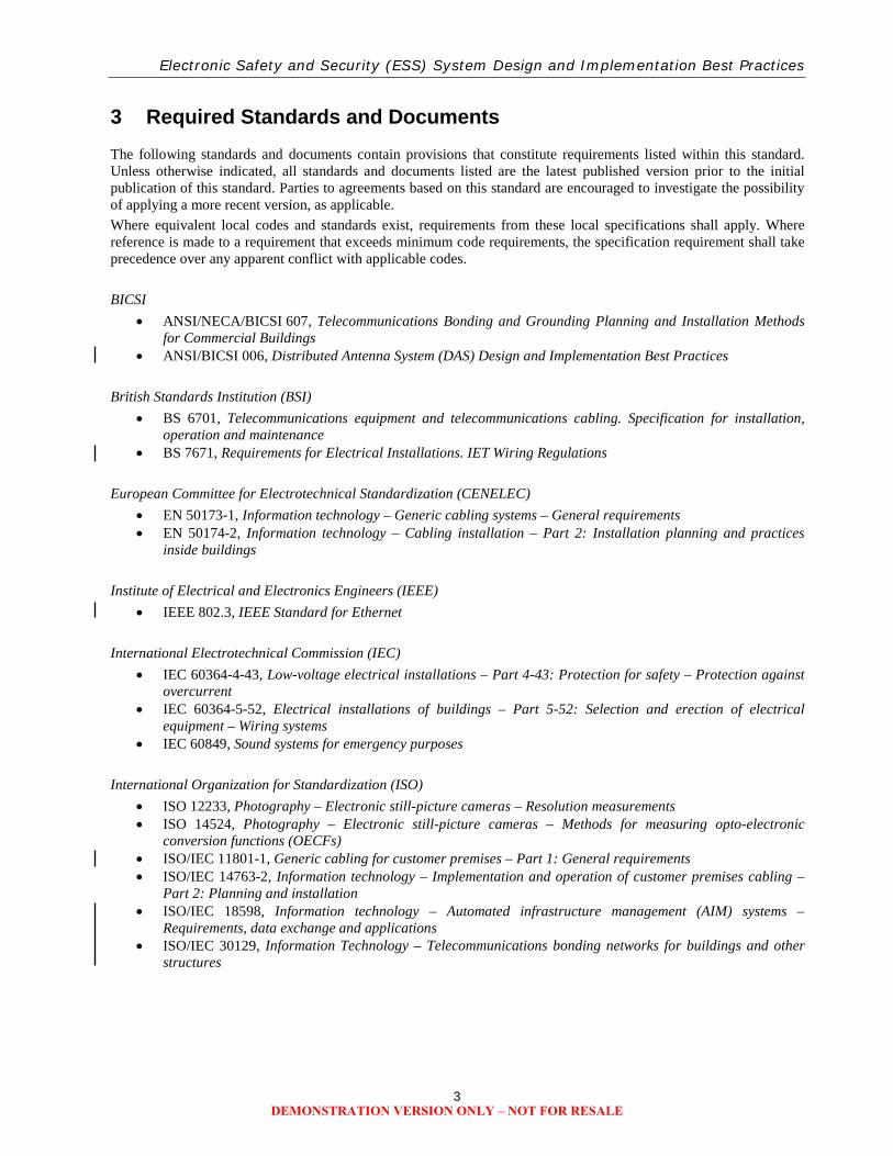
3 Required Standards and Documents The following standards and documents contain provisions that constitute requirements listed within this standard. Unless otherwise indicated, all standards and documents listed are the latest published version prior to the initial publication of this standard. Parties to agreements based on this standard are encouraged to investigate the possibility of applying a more recent version, as applicable. Where equivalent local codes and standards exist, requirements from these local specifications shall apply. Where reference is made to a requirement that exceeds minimum code requirements, the specification requirement shall take precedence over any apparent conflict with applicable codes. BICSI
• ANSI/NECA/BICSI 607, Telecommunications Bonding and Grounding Planning and Installation Methods for Commercial Buildings
• ANSI/BICSI 006, Distributed Antenna System (DAS) Design and Implementation Best Practices British Standards Institution (BSI)
• BS 6701, Telecommunications equipment and telecommunications cabling. Specification for installation, operation and maintenance
• BS 7671, Requirements for Electrical Installations. IET Wiring Regulations European Committee for Electrotechnical Standardization (CENELEC)
• EN 50173-1, Information technology – Generic cabling systems – General requirements • EN 50174-2, Information technology – Cabling installation – Part 2: Installation planning and practices
inside buildings Institute of Electrical and Electronics Engineers (IEEE)
• IEEE 802.3, IEEE Standard for Ethernet International Electrotechnical Commission (IEC)
• IEC 60364-4-43, Low-voltage electrical installations – Part 4-43: Protection for safety – Protection against overcurrent
• IEC 60364-5-52, Electrical installations of buildings – Part 5-52: Selection and erection of electrical equipment – Wiring systems
• IEC 60849, Sound systems for emergency purposes International Organization for Standardization (ISO)
• ISO 12233, Photography – Electronic still-picture cameras – Resolution measurements • ISO 14524, Photography – Electronic still-picture cameras – Methods for measuring opto-electronic
conversion functions (OECFs) • ISO/IEC 11801-1, Generic cabling for customer premises – Part 1: General requirements • ISO/IEC 14763-2, Information technology – Implementation and operation of customer premises cabling –
Part 2: Planning and installation • ISO/IEC 18598, Information technology – Automated infrastructure management (AIM) systems –
Requirements, data exchange and applications • ISO/IEC 30129, Information Technology – Telecommunications bonding networks for buildings and other
structures
DEMONSTRATION VERSION ONLY – NOT FOR RESALE
ANSI/BICSI 005-2016
4
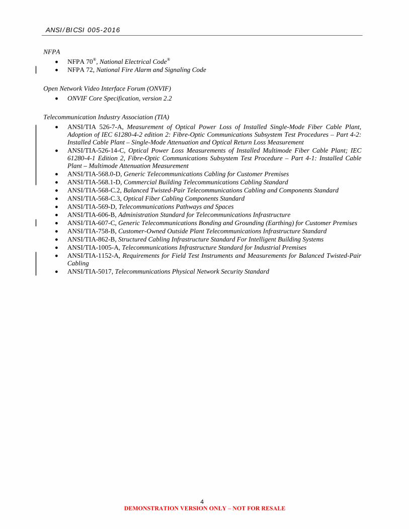
NFPA • NFPA 70®, National Electrical Code® • NFPA 72, National Fire Alarm and Signaling Code
Open Network Video Interface Forum (ONVIF)
• ONVIF Core Specification, version 2.2 Telecommunication Industry Association (TIA)
• ANSI/TIA 526-7-A, Measurement of Optical Power Loss of Installed Single-Mode Fiber Cable Plant, Adoption of IEC 61280-4-2 edition 2: Fibre-Optic Communications Subsystem Test Procedures – Part 4-2: Installed Cable Plant – Single-Mode Attenuation and Optical Return Loss Measurement
• ANSI/TIA-526-14-C, Optical Power Loss Measurements of Installed Multimode Fiber Cable Plant; IEC 61280-4-1 Edition 2, Fibre-Optic Communications Subsystem Test Procedure – Part 4-1: Installed Cable Plant – Multimode Attenuation Measurement
• ANSI/TIA-568.0-D, Generic Telecommunications Cabling for Customer Premises • ANSI/TIA-568.1-D, Commercial Building Telecommunications Cabling Standard • ANSI/TIA-568-C.2, Balanced Twisted-Pair Telecommunications Cabling and Components Standard • ANSI/TIA-568-C.3, Optical Fiber Cabling Components Standard • ANSI/TIA-569-D, Telecommunications Pathways and Spaces • ANSI/TIA-606-B, Administration Standard for Telecommunications Infrastructure • ANSI/TIA-607-C, Generic Telecommunications Bonding and Grounding (Earthing) for Customer Premises • ANSI/TIA-758-B, Customer-Owned Outside Plant Telecommunications Infrastructure Standard • ANSI/TIA-862-B, Structured Cabling Infrastructure Standard For Intelligent Building Systems • ANSI/TIA-1005-A, Telecommunications Infrastructure Standard for Industrial Premises • ANSI/TIA-1152-A, Requirements for Field Test Instruments and Measurements for Balanced Twisted-Pair
Cabling • ANSI/TIA-5017, Telecommunications Physical Network Security Standard
DEMONSTRATION VERSION ONLY – NOT FOR RESALE

Electronic Safety and Security (ESS) System Design and Implementation Best Practices
5
4 Definitions, Acronyms, Abbreviations, and Units of Measurement For the purpose of this standard, the following definitions, acronyms, abbreviations, and units of measurement apply.
4.1 Definitions annunciator A device that provides information on the state or condition of components,
devices or systems(s). In addition to status, the device may display specific status information (e.g., trouble, alarm).
backbone (1) A facility (e.g., pathway, cable, conductors ) between any of the following spaces: telecommunications rooms (TRs), common TRs, floor-serving terminals, entrance facilities, equipment rooms, and common equipment rooms (CER). (2) In a data center, a facility (e.g., pathway, cable, conductors) between any of the following spaces: entrance rooms or spaces, main distribution areas, intermediate distribution areas , horizontal distribution areas , and TRs.
backbone cabling See backbone.
balun An impedance matching transformer used for coupling two electrical circuit elements, where one is balanced (balanced twisted-pair) and the other is unbalanced (coaxial cabling).
campus (1) The buildings and grounds having legal contiguous interconnection (e.g., college, university, industrial park, military installation). (2) A premises containing one or more buildings.
color temperature Characterization of a light source in terms of the temperature of a theoretical blackbody radiator that would have a color (spectral energy density) that most closely resembles that of the illuminating source.
component Any part or subassembly of devices used in the construction of a system (e.g., video surveillance system).
compression The process of encoding or modifying data files from its original form to a file of a smaller size.
credential An item or object that allows the possessor to enter, exit or access an identified space, object or asset.
cross-connect A facility enabling the termination of cabling elements and their interconnection or cross-connection.
device A general term given to the components of a system which perform one or more functions (e.g., detection, measurement, observation), but do not provide system management or complex control functionality. Within an individual ESS discipline (e.g., fire alarm), the term device may be further defined to represent a specific functionality or expected behavior.
digital multimedia content Materials or files that include a combination of text, audio, still images, animation, video, or interactive content forms that are stored as a series of discrete values within an electronic device.
direct attach See modified permanent link.
display A device that shows images, text, or other content by converting analog or digital signals into visible form.
download The process of receiving data at a specific electronic device from another digital source (e.g., computer, network-enabled system, local or remote server).
egress A point or means of exit from a building, property, or location.
encoder A device that converts data into a form suitable for transmission over a specified medium.
DEMONSTRATION VERSION ONLY – NOT FOR RESALE

ANSI/BICSI 005-2016
6
equipment cord A length of cable with connectors on both ends used to join active equipment directly to other active equipment or the cabling infrastructure.
equipment room (telecommunications)
An environmentally controlled centralized space for telecommunications and data processing equipment with supporting communications connectivity infrastructure.
fail-latched A property of a locking device that upon the loss of power, the device will latch or remain latched but does not necessarily restrict movement or access from the secured side.
fail-safe A property of a locking device that upon the loss of power, the device will automatically unlock (open) or remain unlocked (open).
fail-secure A property of a device that upon the loss of power, the device will automatically lock (close) or remain locked (closed).
field of view ’The extent of the observable location or area that is seen at any given moment from a defined point. For ESS devices, the field of view is typically described as an angle on a specified plane (e.g., vertical, horizontal) or as a cone within encompasses two or more planes for which a detector or device will perform its observation function(s). For cameras, the field of view may also be known as the angle of view.
fire detection The means of detecting the occurrence of heat, smoke or other particles or products of combustion.
fire suppression The products, materials, and methods used to control and extinguish an active fire.
forensic review A property of video surveillance equipment, which denotes that the equipment has been optimized to provide high resolution recordings of scene content or digital multimedia content (DMC) captured by the video camera or encoding device.
horizontal cabling (1) The cabling between and including the telecommunications outlet and connector and the horizontal cross-connect. (2) The cabling between and including the building automation system outlet or the first mechanical termination of the horizontal connection point and the horizontal cross-connect. (3) Within a data center, horizontal cabling is the cabling from the horizontal cross-connect (in the main distribution area or horizontal distribution area) to the outlet in the equipment distribution area or zone distribution area.
horizontal connection point A location for connections between horizontal cables that extend from building pathways and horizontal cables that extends to building automation systems (BAS) devices and equipment.
horizontal cross-connect A cross-connect of horizontal cabling to other cabling (e.g., backbone cabling, active equipment).
hybrid cable An assembly of two or more cables, of the same or differing types of media, categories designation, etc., covered by one overall sheath.
interconnection (1) A connection scheme that employs connecting hardware for the direct connection of a cable to another cable without a patch cord or jumper. (2) A type of connection in which single port equipment connections (e.g., 4-pair and optical fiber connectors) attach to horizontal or backbone cabling by means of patch cords or jumpers.
interoperability The ability of two or more systems to communicate and exchange data, while allowing any of the participating systems to use the exchanged information.
DEMONSTRATION VERSION ONLY – NOT FOR RESALE

Electronic Safety and Security (ESS) System Design and Implementation Best Practices
7
jumper An assembly of twisted-pair conductors or balanced twisted-pair, optical fiber, or coaxial cable used to join telecommunications circuits and links at a cross-connect or between patch panels. Jumpers may have connectors at neither, one, or both ends of the assembly.
keypad A data input device consisting of a limited number of keys, each with nominated functions.
Listed Equipment, materials, or services included in a list published by an organization that is acceptable to the authority having jurisdiction (AHJ), that maintains periodic inspection of production of listed equipment or materials or periodic evaluation of services, and whose listing states either that the equipment, material or services meets appropriate standards or has been tested and found suitable for use in a specified manner.
luminance A measure of the brightness of a point on a surface that is radiating or reflecting light.
media (telecommunications) Wire, cable, or conductors used for telecommunications.
media converter A device that converts from one type of media to another. Typically referring to a hardware device that connects different transmission media (i.e., from balanced twisted-pair to coax or from balanced twisted-pair to optical fiber).
metadata Data embedded within or associated with a file that describes information about or related to the file or directory. This may include but is not limited to color, size, trajectory and the locations where the content is stored, dates, times, application specific information, and permissions.
modified permanent link The horizontal cabling on the remote device end directly attaching (or connecting) to the device through a connectorized cable or hard-wired termination, eliminating the need for a telecommunications outlet and equipment cord for the device.
modular plug The insert (“male”) element of a telecommunications connector that may be keyed or unkeyed, typically has six or eight contact positions, of which not all the positions need to be equipped with contacts. A modular plug is named for the number of position and contacts it has (e.g., 8P8C for 8 positions, 8 contacts).
NOTE 1 : The receptacle that a modular plug is inserted into is named a modular jack. NOTE 2: Some specific configurations of a modular plug may be termed as a registered jack or RJ##. An example is a RJ45, which is equivalent to an 8P8C configuration.
observation A function in video surveillance systems that may be optimized to provide continuous viewing of scene content captured by the video camera or encoding device and displayed on local or remote monitors, or on remote display devices like smart-phones, tablets, or laptop computers.
panel An electrical device consisting of an enclosure, box or surface that may contain switches, dials, displays or meters for controlling or monitoring other electrical devices.
patch cord A jumper with connectors on both ends used to join telecommunications circuits/links, for example between two patch panels.
patch panel A connecting hardware system that facilitates cable termination and cabling administration using patch cords.
pathway (telecommunications)
A facility for the placement of telecommunications cable.
DEMONSTRATION VERSION ONLY – NOT FOR RESALE
ANSI/BICSI 005-2016
8
pixel In digital imaging, a single point in a bitmap image, or the smallest addressable screen element in a display device. It is the smallest unit of a picture that can be represented or controlled.
proprietary A characteristic of a technique, technology, or device which is owned and controlled by a company or other party and is thereby only usable or adaptable as allowed by that party and not deemed to achieve interoperability.
raceway An enclosed channel of metal or nonmetallic materials designed expressly for holding wires or cables. Raceways include, but are not limited to: rigid metal conduit, rigid nonmetallic conduit, rigid nonmetallic conduit, intermediate metal conduit, liquid tight flexible conduit, flexible metallic tubing, flexible metal conduit, electrical nonmetallic tubing, electrical metallic tubing, underfloor raceways, cellular, cellular concrete floor raceways, cellular metal floor raceways, surface raceways, wireways, and busways.
NOTE: Cable tray is not considered a type of raceway.
recognition In ESS systems, a function used to capture and record imagery that may include, but not be limited to, vehicle license plate recognition, facial recognition, smoke and fire detection, object recognition, pattern recognition, cross-line detection, object temporal characteristics, color recognition and trajectory.
recording media Any device or component to which digital multimedia content (DMC) is written, stored and can be retrieved.
single connector modified permanent link
A test procedure for a Category 5e/Class D or higher modified permanent link plug-ended configuration where the fixed length of cabling is punched down at the near end patch panel and an eight position modular plug is attached at the device far end. The test equipment utilizes a test equipment cord on the near end attached to a permanent link adapter and is directly attached to a channel adapter at the far end. A consolidation point may optionally be located between the near and far ends.
soft space In architectural spaces, virtual spaces adjacent to actual spaces that permit expansion of an actual space into the virtual space if required at a later date (e.g., expansion of a telecommunications room). Examples of architectural spaces by this definition include: storage spaces, conference rooms, unassigned coverage areas, or other spaces not located within the life safety egress path to allow for future expansion.
space (telecommunications) An area whose primary function is to house the installation and termination of telecommunications equipment and cable (e.g., equipment room, telecommunications room, entrance facility).
telecommunications Any transmission, emission, and reception of information (e.g., signs, signals, writings, images, sounds) by cable, radio, optical, or other electromagnetic systems.
telecommunications connector
The receptacle and insertion elements which provide a means of aligning, attaching and achieving continuity between the conductors and optical fibers used within telecommunication and ICT applications.
telecommunications outlet An assembly of which consists of a faceplate, body, housing, or supporting bracket, and one or more receptacles or jacks of a telecommunication connector.
telecommunications room A telecommunications space that differs from equipment rooms and entrance facilities in that this space is generally considered a floor-serving or tenant-serving (as opposed to building- or campus-serving) space that provides a connection point between backbone and horizontal cabling.
termination The physical connection of a conductor to connecting hardware.
topology The physical or logical arrangement of a system.
DEMONSTRATION VERSION ONLY – NOT FOR RESALE
Electronic Safety and Security (ESS) System Design and Implementation Best Practices
9
uninterruptible power supply A system that provides a continuous supply of power to a load, utilizing stored energy when the normal source of energy is not available or is of unacceptable quality. A UPS will provide power until the stored energy of the system has been depleted, or when the acceptable quality of either an alternative source of power (e.g., generator) or the normal source of power becomes available.
use case A list of steps, typically defining interactions between a role and a system, to achieve a goal. The actor can be a human or an external system.
varistor An electronic component used to protect circuits against excessive transient voltages by incorporating them into the circuit in such a way that, when triggered, they will shunt the current created by the high voltage away from the sensitive components. Also known as a voltage dependent resistor.
video monitor A type of display for the viewing of live and recorded video. A video monitor may also be known as a digital panel.
4.2 Acronyms and Abbreviations Abbreviations and acronyms, other than in common usage, are defined below.
AC alternating current ACS access control system AFF above finished floor AHJ authority having jurisdiction AIM automated infrastructure management AWG American wire gauge BAS building automation system BIM building information modeling BMS building management system CCTV closed circuit television CRI color rendition index DAS distributed antenna system DC direct current DMC digital multimedia content EMI electromagnetic interference EMT electrical metallic tubing ER equipment room ESS electronic safety and security FOV field of view GPS global positioning system GUI graphical user interface HCP horizontal connection point HDTV high definition television HVAC heating, ventilation, and air conditioning ICS integrated control system ICT information communication and
technology IDS intrusion detection system IP Internet protocol
LAN local area network NAC notification appliance circuit NC normally closed NO normally open NRTL nationally recognized testing laboratory PDS protected distribution system PIR passive infrared PLC programmable logic circuit PoE power over Ethernet POTS plain old telephone service PSE power sourcing equipment PSIM physical security information management PTP point-to-point PTZ pan, tilt, zoom QoS quality of service RAID redundant array of independent disks REX request to exit RF radio frequency RFID radio frequency identification SCADA supervisory control and data acquisition TCP/IP transmission control protocol/internet
protocol TE telecommunications enclosure TR telecommunications room UPS uninterruptible power supply USB universal serial bus UTP unshielded balanced twisted-pair VSS video surveillance system WAN wide area network
DEMONSTRATION VERSION ONLY – NOT FOR RESALE

ANSI/BICSI 005-2016
10
4.3 Units of Measurement The units of measurement used in this standard are metric. Approximate conversions from metric to U.S. customary units are provided in parentheses; e.g., 100 millimeters (4 inches). Units of measurement used in this standard are defined below:
Ah ampere-hour dB decibel dBA ambient decibel adjusted for frequency fps frames per second ft foot ft2 square foot GHz gigahertz Hz hertz in inch km kilometer lbf pound force m meter m2 square meter Mb/s megabit per second MHz megahertz mi mile mm millimeter N newton nm nanometer ppf pixels per foot ppm pixels per meter VAC volt alternate current VDC volt direct current W watt
DEMONSTRATION VERSION ONLY – NOT FOR RESALE

Electronic Safety and Security (ESS) System Design and Implementation Best Practices
11
5 Telecommunications Infrastructure
5.1 Overview ESS systems may either share the collective set of cabling system components, cabling pathways, and related telecommunications spaces with a traditional voice/data information and communications technology (ICT) network or use a dedicated ESS network operating in parallel with the traditional voice/data information ICT network. Regardless of the way that these systems are deployed, telecommunications cabling infrastructure standards and telecommunications cabling installation best practices should be observed. This section addresses the best practices for the design and installation of a telecommunications cabling infrastructure for ESS devices to support a wide range of applications. The basic elements of the telecommunications infrastructure are the following:
• Topology • Equipment room (ER) • Telecommunications room (TR) • Telecommunications enclosure (TE) • Backbone cabling • Horizontal cabling • Cabling pathways • Telecommunications outlets and connectors • Coverage areas
The diversity of ESS services currently available, coupled with the continual addition of new services, means that there may be cases where limitations to desired performance may occur. When applying specific applications to these telecommunications cabling systems, the user is cautioned to consult existing codes, regulations, application standards, equipment manufacturer requirements, and system and service suppliers for applicability, limitations, and ancillary requirements.
5.2 Topology 5.2.1 Star Topology 5.2.1.1 Requirements The topology for horizontal and backbone cabling shall be configured as a star (horizontal) or hierarchical star (backbone). See Figure 5-1 for an example of a hierarchical star topology. 5.2.1.2 Recommendations Horizontal cabling topology should be planned to allow the deployment of numerous ESS services within the ICT network. Services and their associated devices include, but are not limited to:
• Surveillance and security cameras • Access control devices • Intrusion detection sensors and notification
devices • Fire alarm control panels, sensors, and
annunciators • Other specialty applications (e.g., asset
management, mass notification)
Figure 5-1
Hierarchical Star Topology
5.2.2 Non-Star Topologies 5.2.2.1 Overview Non-star based topologies may be used in order to accommodate other ICT services and associated cabling infrastructure. For example, ancillary systems cabling from a master control panel to a remote device. Examples of non-star topologies that are commonly used are shown in Figure 5-2.
Campus Distributor (Main Cross-Connect)
Floor Distributor (Horizontal Cross-Connect)
Building Distributor (Intermediate Cross-Connect)
Telecommunications Outlet / Connector
DEMONSTRATION VERSION ONLY – NOT FOR RESALE
Electronic Safety and Security (ESS) System Design and Implementation Best Practices
31
6 Intrusion Detection Systems
6.1 Overview An intrusion detection system (IDS) detects unauthorized entry into a protected area. Its methodology of operation is to detect an intrusion and provide some form of notification that a breach has occurred in the area under protection. An IDS is an integration of the following components and devices:
• Field devices consisting of a system keypad(s), detection sensors, and annunciators • Processor controllers • Notification panels and console(s) • Power source
Typically, an IDS panel will monitor door and window contacts to annunciate an alarm upon an unauthorized opening. These systems can be expanded to include motion detection, glass break sensors, and even video motion detection and recording. In addition, the system can be connected to smoke detectors, water leak sensors, and a variety of other monitoring devices to allow integration with a building management system (BMS). An IDS may include software applications that monitor network or system activities for malicious activities or policy violations. Additionally, an IDS may produce reports to a management station.
6.2 Developing an IDS 6.2.1 Requirements The primary requirements when developing an IDS are as follows:
• An IDS shall be used to identify a security breach of unauthorized entry for the exterior building perimeter, interior building security boundaries, and exterior site perimeter.
• Use of detection sensors, devices that monitor and detect forced and unauthorized entry into a protected area. • Use of processor controllers, systems that receive and process outputs from connected sensors and use
predefined parameters to generate alerts based on the information received from each sensor. • Use of a notification console, a device that monitors events and system alerts that operators can use to make
informed decisions as to the operational status of the entire IDS. • Use of power source, low-voltage transformers and backup batteries.
6.2.2 Recommendations The primary recommendations when developing an IDS are as follows:
• IDS panels should be monitored from a central monitoring station to provide enhanced security. • IDS should be tied into a local alerting system and into a police station or a private security station. • IDS should be capable of alerting homeowners and business owners via pager, telephone, or Internet.
6.3 System Connectivity 6.3.1 Wired Devices 6.3.1.1 Overview The following is the typical required cabling for an addressable device system:
• Panel to keypad: 4-conductor stranded 0.823 mm2 (18 AWG) • Panel to addressable devices: 1-pair twisted 0.823 mm2 (18 AWG) • Panel to powered device: 1-pair 0.823 mm2 (18 AWG) • Conventional device to addressable module: 1-pair 0.326 mm2 (22 AWG)
The following is the typical required cabling for a conventional device system: • Panel to keypad: 4-conductor non-twisted 0.823 mm2 (18 AWG) • Panel to device: 2-conductor 0.326 mm2 (22 AWG) • Communication bus: 4-conductor 0.823 mm2 (18 AWG) • Panel to powered device: 2-conductor 0.823 mm2 (18 AWG)
6.3.1.2 Requirements Any telecommunications or ICT cabling required for an IDS shall be of a type listed in Section 5.4.
DEMONSTRATION VERSION ONLY – NOT FOR RESALE

Electronic Safety and Security (ESS) System Design and Implementation Best Practices
37
7 Video Surveillance
7.1 Overview Video surveillance is the extension of human vision to areas requiring surveillance. Discussions regarding surveillance system deployment, integration, monitoring, and convergence often lead to the determination of functional needs. Some primary applications of this technology include:
• Observation • Investigation and forensic review • Recognition of objects (e.g., human faces, license plates) • Prosecution • Loss prevention and deterrence • Intrusion detection and perimeter monitoring • Access control • Operations management and resource allocation • Safety • Security
This section applies to video surveillance systems deployed for use cases listed in the following text, but may also be applicable to other uses not cited. When planning video surveillance systems, like all ESS systems, device performance in unanticipated conditions and potential interdependencies with other external devices, systems, and infrastructure should be included, as elements to be addressed for achieving the highest level of fault tolerance possible.
7.2 Generation and Conformance with Use Cases 7.2.1 Scene Characteristics 7.2.1.1 Introduction The video surveillance system (VSS) use case is defined by the scene characteristics and the specification of the VSS function(s). 7.2.1.2 Requirements 7.2.1.2.1 Scene The scene shall be identified to include one or more areas of interest or scene content. The VSS shall present a scene of interest to a user in sufficient detail to make a decision or perform a task based on recognition of what is happening in the scene. For example, an end user may wish to be able to read the characters in a license plate, or determine the identities of individuals at a local convenience store while performing surveillance. The VSS shall be designed to accomplish one or more specific tasks regarding a scene. The primary functions of the VSS shall be identified as one of the following:
• Observation • Forensic review • Recognition
The VSS scene content criteria shall incorporate resolution, object size, speed, trajectory, scene lighting level, and required refresh rate. 7.2.1.2.2 Resolution Resolution, as required by the VSS primary function, and shall be measured in pixels per meter (ppm) or pixels per foot (ppf). The pixels per meter or foot calculation shall be derived for both horizontal and vertical pixels and is equal to the imager’s pixel dimensions divided by the corresponding field of view linear dimension (meter or feet). The use of video cameras and encoding technology with built-in pixel counting shall be considered as an enhancement to the design process, measurement and verification of pixels on target.
DEMONSTRATION VERSION ONLY – NOT FOR RESALE

Electronic Safety and Security (ESS) System Design and Implementation Best Practices
45
8 Access Control Systems
8.1 Overview Access control refers to the practice of controlling access to a property, building, or select space within a facility for authorized persons only. Currently, a wide variety of mechanical and electronic hardware devices are used to protect or prevent unauthorized access to important items or to restrict access to protected areas and valuable information. These devices vary from traditional physical keys and locks to elaborate electronic access systems capable of recognizing the biographical and biometric data of system users prior to granting access to secure spaces.
8.2 System Structure 8.2.1 Overview The minimum of required components for an ACS include a computer, a control panel, and a peripheral device connected to the control panel. An ACS may be more complex, having multiple control panels and peripheral devices, and may use additional components, such as credentials. The components of ACS may be classified into the following levels:
• Level 1 – Central equipment processing, recording, software, and database • Level 2 – Controllers for intelligent field processing (e.g., data gathering panel) • Level 3 – Peripheral devices (e.g., card reader, lock, door position switch) • Level 4 – Credentials (e.g., cards, fobs, biometrics, personal identification numbers [PINs], passwords)
8.2.2 Central Equipment Processing (Level 1) 8.2.2.1 Overview The host computer or server runs the access control software, manages the system parameters, maintains the system database, and controls all communication with the control panels. The host computer receives all event and alarm transactions from the control panels. It then saves them into separate history files that may be used to run reports by specific criteria. The host computer may provide a GUI to simplify various tasks an operator would need to accomplish within the ACS. For instance, multiple screens in most access control software are object oriented, allowing operators to use the point-and-click method to highlight a text box and type the data, disable an input point, or control an output device. A graphical map of the campus or a detailed CAD drawing of a building may display on a monitor to indicate an alarm location, or a window may display a live video (when integrated with a VSS) of the person pushing the intercom button to request entry into the lobby. 8.2.3 Computer Hardware and Software 8.2.3.1 Recommendations Computer hardware used within an ACS should exceed the manufacturer’s minimum requirements for processor speed, memory, and drive size. If the computer will be used for the badging station, the size and type may depend on the space required by the video capture cards. The size and type of monitor used with the ACS may depend on the location and purpose. In certain high-sensitivity/security environments, redundant computer hardware may be required to ensure system availability and reliability. 8.2.4 Server 8.2.4.1 Overview Typically, an ACS database resides on a server. The ACS server(s) may be in a number of locations, depending on the application. It may be collocated with IT servers in a computer room or be a stand-alone computer in an office. The server commonly runs a number of applications (e.g., badging software, card entry software) that are part of the card access system. A large server typically runs the database only. Certain applications may require the use of dedicated or multiple servers. The server communicates with ACS components through various media. Some examples are:
• Hardwired or wireless connections to the card reader panels and other devices • IP communications through a network to either the card reader panels or remote workstations • Telephone modem connection to off-campus reader panels
DEMONSTRATION VERSION ONLY – NOT FOR RESALE
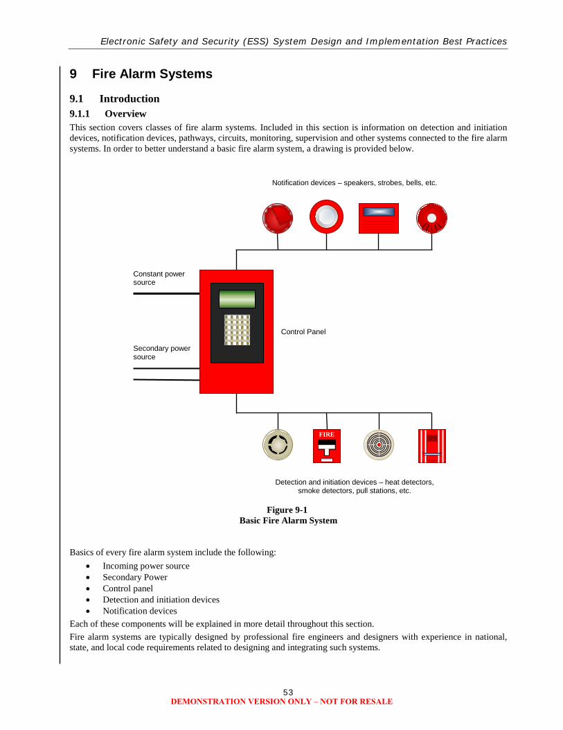
Electronic Safety and Security (ESS) System Design and Implementation Best Practices
53
9 Fire Alarm Systems
9.1 Introduction 9.1.1 Overview This section covers classes of fire alarm systems. Included in this section is information on detection and initiation devices, notification devices, pathways, circuits, monitoring, supervision and other systems connected to the fire alarm systems. In order to better understand a basic fire alarm system, a drawing is provided below.
Figure 9-1
Basic Fire Alarm System
Basics of every fire alarm system include the following:
• Incoming power source • Secondary Power • Control panel • Detection and initiation devices • Notification devices
Each of these components will be explained in more detail throughout this section. Fire alarm systems are typically designed by professional fire engineers and designers with experience in national, state, and local code requirements related to designing and integrating such systems.
Notification devices – speakers, strobes, bells, etc.
Constant power source
Secondary power source
Detection and initiation devices – heat detectors, smoke detectors, pull stations, etc.
FIRE
Control Panel
DEMONSTRATION VERSION ONLY – NOT FOR RESALE