Embed Size (px)
Citation preview
1
European Organization for Nuclear Research (CERN)
Geneva-1121, Switzerland
Electronic Readout Improvement of
HMPID in ALICE
Supervisor: Giacomo Volpe (PH-AID-DT)
Mentor: Lazzaro Manlio Minervini (PH-UAI)
Summer Student: Usman Amin Fiaz (PH-AID-DT) [PAKISTAN]
2
1. INTRODUCTION
ALICE (A Large Ion Collider Experiment) is an experiment at the Large Hadron
Collider (LHC) optimized for the study of heavy-ion collisions, at SNN = 2.76 TeV. The
prime aim of the experiment is to study in detail the behavior of matter at high
densities and temperatures, in view of probing deconfinement and chiral symmetry
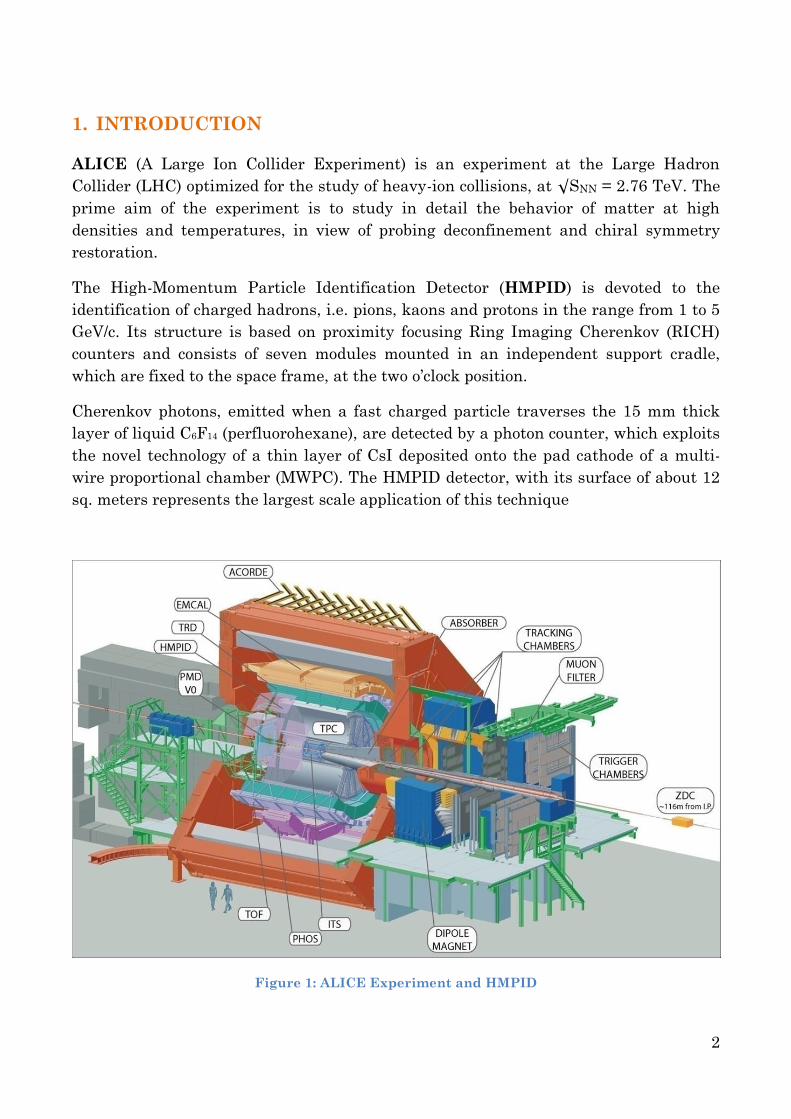
restoration. The High-Momentum Particle Identification Detector (HMPID) is devoted to the
identification of charged hadrons, i.e. pions, kaons and protons in the range from 1 to 5
GeV/c. Its structure is based on proximity focusing Ring Imaging Cherenkov (RICH)
counters and consists of seven modules mounted in an independent support cradle,
which are fixed to the space frame, at the two o’clock position.
Cherenkov photons, emitted when a fast charged particle traverses the 15 mm thick
layer of liquid C6F14 (perfluorohexane), are detected by a photon counter, which exploits
the novel technology of a thin layer of CsI deposited onto the pad cathode of a multi-
wire proportional chamber (MWPC). The HMPID detector, with its surface of about 12
sq. meters represents the largest scale application of this technique
Figure 1: ALICE Experiment and HMPID
3
The Cherenkov photons refract out of the liquid radiator and reach the CsI-coated pad
cathode, located at a suitable distance (the `proximity gap`) that allows the contribution
of the geometrical aberration to the Cherenkov angle resolution to be reduced. The
electrons released by ionizing particles in the proximity gap, filled with CH4, are
prevented from entering the MWPC sensitive volume by a positive polarization of the
`collection` electrode close to the radiator.
2. ELECTRONIC READOUT
The readout of the HMPID modules is organized according to parallel/serial
architecture and is based on the VLSI GASSIPLEX chip, specifically developed to
enable the determination of the hit coordinates by centroid measurement. It is
characterized by a filtering scheme designed to cope with the shape of the signal
delivered by MWPCs and by a long peaking time (1.2 ms) suitable for an external event
trigger. An average noise of 1000 e- has been measured on detector.
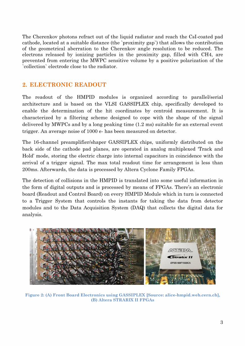
The 16-channel preamplifier/shaper GASSIPLEX chips, uniformly distributed on the
back side of the cathode pad planes, are operated in analog multiplexed ‘Track and
Hold’ mode, storing the electric charge into internal capacitors in coincidence with the
arrival of a trigger signal. The max total readout time for arrangement is less than
200ms. Afterwards, the data is processed by Altera Cyclone Family FPGAs.
The detection of collisions in the HMPID is translated into some useful information in
the form of digital outputs and is processed by means of FPGAs. There’s an electronic
board (Readout and Control Board) on every HMPID Module which in turn is connected
to a Trigger System that controls the instants for taking the data from detector
modules and to the Data Acquisition System (DAQ) that collects the digital data for
analysis.
Figure 2: (A) Front Board Electronics using GASSIPLEX [Source: alice-hmpid.web.cern.ch],
(B) Altera STRARIX II FPGAs
4
3. IMPROVEMENT
Previously the FPGAs are programmed in an old version of Hardware description
language called AHDL. The improvement of HMPID Readout could be carried out just
by improving the language to a better, high level and modern language: the VHDL.
But why merely translation is improvement?
AHDL is an old version of HDL
If you’re going to work with the Engineers of new era, one needs to shift to VHDL
because it’s the latest version of hardware description language.
VHDL is a higher level language
In programming languages the more high level means more close to human
understanding; AHDL is less understandable in sense that you need to take care of
the hardware aspect while writing the code, while in VHDL the compiler takes care
of the hardware; you just need to devise an algorithm.
Very few comments in older codes (Also in Italian)
Another aspect of improvement is that older codes were not oriented in a way that is
easily understandable to a new comer. There were very few comments in Italian
that were not very clear regarding the working logic of the code. The comments are
now modified with clarity and language is changed to English for better
understanding.
Code Complexity
The AHDL code is itself complex at times due to more number of instructions. This
complexity and length of the code is greatly reduced in case of VHDL due to strong
instruction set.
Synchronization
The VHDL code provides the ability to synchronize the circuit enclosing instances in
processes managed by a single clock signal.
Processing Efficiency
Being a newer version of HDL, VHDL files take less compilation and burning time
than respective AHDL files reducing the required processing power.
Debugging
And last but not the least, the debugging of the FPGAs is very easy in case of VHDL
as compared to AHDL that makes working and correction of codes comfortable.
4. PROGRAMMING
The real challenge of the project was to translate the
AHDL codes with very low information in terms of
comments, to VHDL without making any difference in
basic routine of the program. Algorithms were varied
in order to get more efficient and simple hardware,
where ever applicable. For the programming Quartus
II v10.1 was used as an environment.
5
The verification of these codes required simulating both the AHDL and VHDL files for
the desired outputs that should necessarily be the same. I was actually able to do some
simulations of VHDL files in Modelsim but those simulations were not very easy and
clear for AHDL files. So it will be better for the guys who wish to carry on this project
to use some other simulation environment for the verification and testing purposes.
5. EXAMPLE CODE
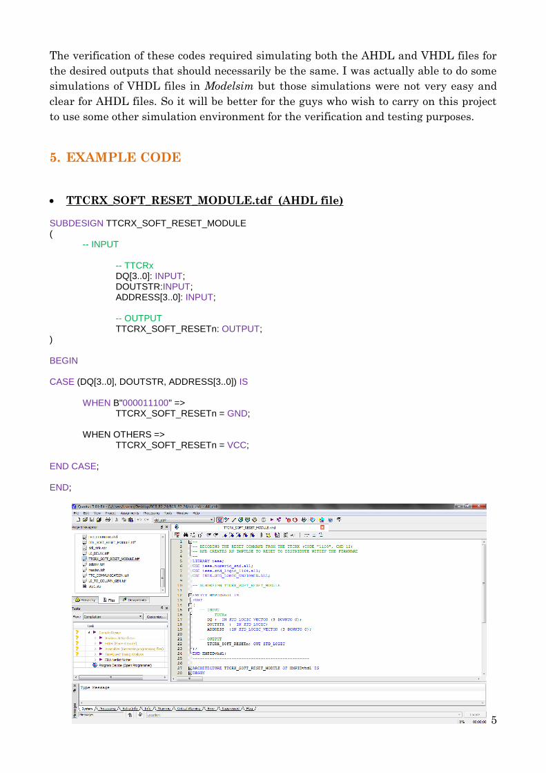
TTCRX_SOFT_RESET_MODULE.tdf (AHDL file)
SUBDESIGN TTCRX_SOFT_RESET_MODULE ( -- INPUT -- TTCRx DQ[3..0]: INPUT; DOUTSTR:INPUT; ADDRESS[3..0]: INPUT; -- OUTPUT TTCRX_SOFT_RESETn: OUTPUT; ) BEGIN CASE (DQ[3..0], DOUTSTR, ADDRESS[3..0]) IS WHEN B"000011100" => TTCRX_SOFT_RESETn = GND; WHEN OTHERS => TTCRX_SOFT_RESETn = VCC; END CASE; END;
6
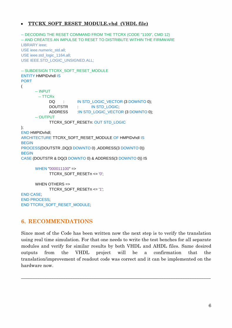
TTCRX_SOFT_RESET_MODULE.vhd (VHDL file)
-- DECODING THE RESET COMMAND FROM THE TTCRX (CODE "1100", CMD 12)
-- AND CREATES AN IMPULSE TO RESET TO DISTRIBUTE WITHIN THE FIRMWARE
LIBRARY ieee;
USE ieee.numeric_std.all;
USE ieee.std_logic_1164.all;
USE IEEE.STD_LOGIC_UNSIGNED.ALL;
-- SUBDESIGN TTCRX_SOFT_RESET_MODULE
ENTITY HMPIDvhdl IS
PORT
(
-- INPUT
-- TTCRx
DQ : IN STD_LOGIC_VECTOR (3 DOWNTO 0);
DOUTSTR : IN STD_LOGIC;
ADDRESS :IN STD_LOGIC_VECTOR (3 DOWNTO 0);
-- OUTPUT
TTCRX_SOFT_RESETn: OUT STD_LOGIC
);
END HMPIDvhdl;
ARCHITECTURE TTCRX_SOFT_RESET_MODULE OF HMPIDvhdl IS
BEGIN
PROCESS(DOUTSTR ,DQ(3 DOWNTO 0) ,ADDRESS(3 DOWNTO 0))
BEGIN
CASE (DOUTSTR & DQ(3 DOWNTO 0) & ADDRESS(3 DOWNTO 0)) IS
WHEN "000011100" =>
TTCRX_SOFT_RESETn <= '0';
WHEN OTHERS =>
TTCRX_SOFT_RESETn <= '1';
END CASE;
END PROCESS;
END TTCRX_SOFT_RESET_MODULE;
6. RECOMMENDATIONS
Since most of the Code has been written now the next step is to verify the translation
using real time simulation. For that one needs to write the test benches for all separate
modules and verify for similar results by both VHDL and AHDL files. Same desired
outputs from the VHDL project will be a confirmation that the
translation/improvement of readout code was correct and it can be implemented on the
hardware now.
_________________________________________________________________________________
7
ABOUT
USMAN AMIN FIAZ |House# 2, Street# 8, Block-F, Soan Gardens | Islamabad, Pakistan | |Mobile: +92-334-9570527 / Residence: +92-51-5738474 | | [email protected] | [email protected] | Objective: A highly motivated and ambitious Electrical Engineer with excellent academic credentials and comprehensive knowledge of the field, seeking to join an organization that allows me to grow professionally by giving the chance to utilize my technical and management skills for the betterment of the organization, with the best use of my dedication, determination and resourcefulness.
EDUCATION
Bachelor of Science, Electrical Engineering (BSEE) CGPA:3.99 Pakistan Institute of Engineering and Applied Sciences, (PIEAS) Islamabad, Pakistan.
(Expected June 2015)
Major: Electrical
Minor: Electronics
Related Courses: Basic Electrical Engineering, Basic Electronics, Differential Equations, Calculus-I/II, Computer Aided Design,
Digital Logic Design, Network Analysis, Integrated Electronics, Microprocessors and Interfacing, Electrical Machines-I/II,
Signals and Systems Theory, Electromagnetic Theory, Power Electronics, Power Generation, Transmission and Distribution.
Projects:
Design & Implementation of Regulated DC Power Supply
Design and Implementation of 8088 microprocessor based Single Board Computer
Design of a Stair Climbing robot able to ascend stairs at the rate of at least one stair per minute and keep a payload to
the ground during the stair climbing action. (CAD Project)
Design of timing sequential circuit for a 4 way traffic signal
Design and implementation of an Audio Amplifier.
Design and Implementation of a line tracking robot (Ongoing project)
SKILLS & ABILITIES
Leadership: Chairperson IEEE PIEAS Student Branch. (2013-Present)
Head Theme Applied Sciences, PIEAS Thematic Society. (2013-Present)
Management:
As the above mentioned post holder, organized;
IEEE Insight, MATLAB/GRE Workshops
Cyber Security Awareness/ Microcontroller Workshops
Couple of technical events; ‘Construct a Thon’ and ‘Pi-Electric’
Memberships:
Member IEEE and IEEE PIEAS Student Branch. (2013-Present)
Executive Member Autodesk Education Community (USA). (2011-Present)
EXPERIENCE
Instrumentation Control and Computer Complex, ICCC Islamabad, Pakistan.
(June 2013 to August 2013)
Six-Week Summer Internship at Instrumentation Control and Computer Complex (ICCC), PAEC. The internship included the hands on experience in six different fields; Robotics, Software/Cryptography, Microcontrollers, Networking, Telecommunication & Embedded systems - FPGA’s.
RESEARCH
Pakistan Institute of Engineering & Applied Sciences (PIEAS), Islamabad, Pakistan.
(February 2014 to Present)
Currently working on the Adaptive state observer for Lipschitz nonlinear systems. (A research based project) – with Dr. Muhammad Rehan (PIEAS)