Embed Size (px)
Citation preview
1069
Mechanicalpressure SW
Electronicpressure SW
Pressure SWfor coolant
Smallflow sensor
Smallflow controller
Flow sensorfor air
Flow sensorfor water
Air sensor
Ele
ctro
nic
pres
sure
sw
itch
Pre
ssur
e se
nsor
Speedcontrol valve
Check valve/ others
Magneticspring buffer
Contact / closecontact conf.SW
Refrigeratingtype dryer
Desiccanttype dryer
High polymermembranetype dryer
Auto. drain/ others
F.R.L.(Module unit)
F.R.L.(Separate)
F.R.L.(Relatedproducts)
CleanF.R.
Airbooster
Joint/ tube
Suctionplate
Total airsystem
Total airsystem(Gamma)
Air filter
CompactF.R.
Preciseregulator
Electropneumaticregulator
Silencer
Vacuumregulator
Ending
Vacuumfilter
C O N T E N T S
� Sensors / pressure sensor
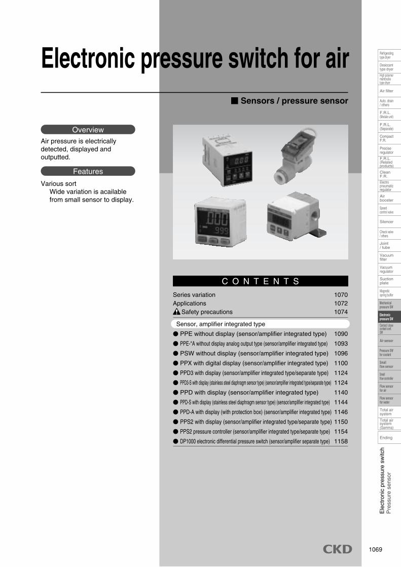
Electronic pressure switch for air
Air pressure is electrically detected, displayed and outputted.
Overview
Various sortWide variation is acailable from small sensor to display.
Features
Series variation 1070Applications 1072 Safety precautions 1074
Sensor, amplifier integrated type
� PPE without display (sensor/amplifier integrated type) 1090
� PPE-*A without display analog output type (sensor/amplifier integrated type) 1093
� PSW without display (sensor/amplifier integrated type) 1096
� PPX with digital display (sensor/amplifier integrated type) 1100
� PPD3 with display (sensor/amplifier integrated type/separate type) 1124
� PPD3-S with display (stainless steel diaphragm sensor type) (sensor/amplifier integrated type/separate type) 1124
� PPD with display (sensor/amplifier integrated type) 1140
� PPD-S with display (stainless steel diaphragm sensor type) (sensor/amplifier integrated type) 1144
� PPD-A with display (with protection box) (sensor/amplifier integrated type) 1146
� PPS2 with display (sensor/amplifier integrated type/separate type) 1150
� PPS2 pressure controller (sensor/amplifier integrated type/separate type) 1154
� DP1000 electronic differential pressure switch (sensor/amplifier separate type) 1158
1070
Ending
Speedcontrol valve
Check valve/ others
Magneticspring buffer
Refrigeratingtype dryer
Desiccanttype dryer
High polymermembranetype dryer
Auto. drain/ others
F.R.L.(Module unit)
F.R.L.(Separate)
F.R.L.(Relatedproducts)
CleanF.R.
Airbooster
Joint/ tube
Suctionplate
Total airsystem
Total airsystem(Gamma)
Air filter
CompactF.R.
Preciseregulator
Electropneumaticregulator
Silencer
Vacuumregulator
Vacuumfilter
Contact / closecontact conf.SW
Mechanicalpressure SW
Electronicpressure SW
Pressure SWfor coolant
Smallflow sensor
Smallflow controller
Flow sensorfor air
Flow sensorfor water
Air sensor
Seriesvariation
1071
Mechanicalpressure SW
Electronicpressure SW
Pressure SWfor coolant
Smallflow sensor
Smallflow controller
Flow sensorfor air
Flow sensorfor water
Air sensor
Ele
ctro
nic
pres
sure
sw
itch
Pre
ssur
e se
nsor
Speedcontrol valve
Check valve/ others
Magneticspring buffer
Contact / closecontact conf.SW
Refrigeratingtype dryer
Desiccanttype dryer
High polymermembranetype dryer
Auto. drain/ others
F.R.L.(Module unit)
F.R.L.(Separate)
F.R.L.(Relatedproducts)
CleanF.R.
Airbooster
Joint/ tube
Suctionplate
Total airsystem
Total airsystem(Gamma)
Air filter
CompactF.R.
Preciseregulator
Electropneumaticregulator
Silencer
Vacuumregulator
Ending
Vacuumfilter
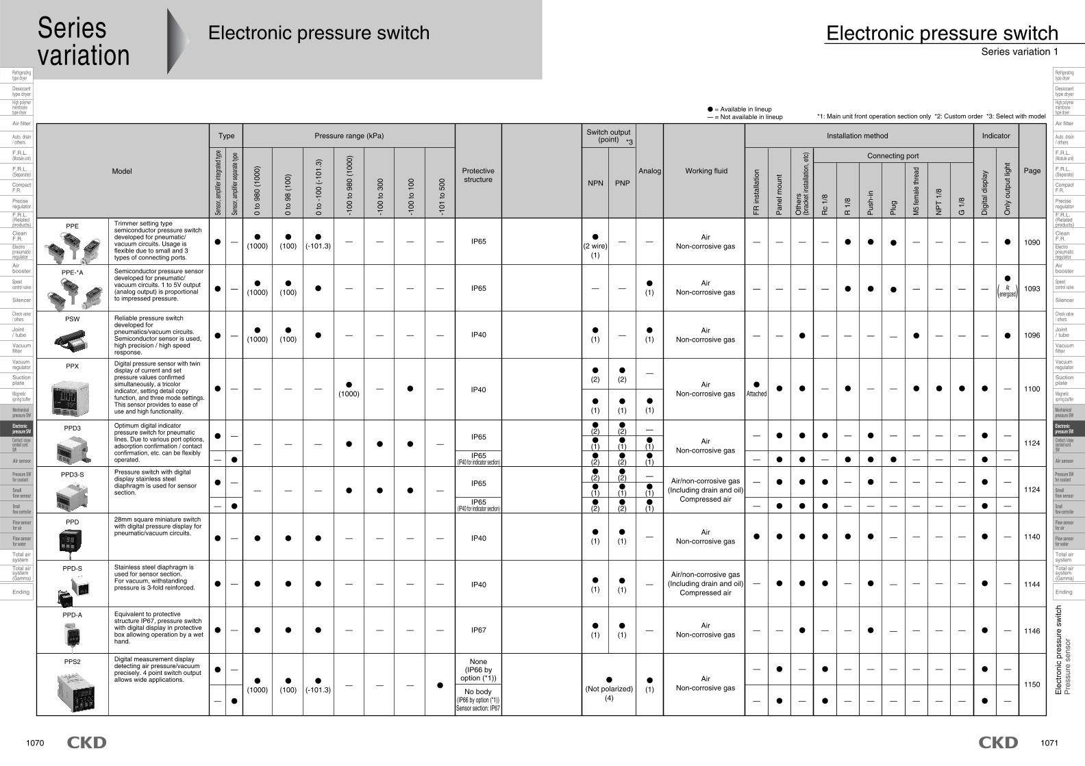
*1: Main unit front operation section only *2: Custom order *3: Select with model
Model
Trimmer setting type semiconductor pressure switch developed for pneumatic/ vacuum circuits. Usage is flexible due to small and 3 types of connecting ports.
Semiconductor pressure sensor developed for pneumatic/ vacuum circuits. 1 to 5V output (analog output) is proportional to impressed pressure.
Reliable pressure switch developed for pneumatics/vacuum circuits. Semiconductor sensor is used, high precision / high speed response.
28mm square miniature switch with digital pressure display for pneumatic/vacuum circuits.
Equivalent to protective structure IP67, pressure switch with digital display in protective box allowing operation by a wet hand.
Stainless steel diaphragm is used for sensor section. For vacuum, withstanding pressure is 3-fold reinforced.
Optimum digital indicator pressure switch for pneumatic lines. Due to various port options, adsorption confirmation / contact confirmation, etc. can be flexibly operated.
Digital pressure sensor with twin display of current and set pressure values confirmed simultaneously, a tricolor indicator, setting detail copy function, and three mode settings. This sensor provides to ease of use and high functionality.
Type Pressure range (kPa) Switch output(point) *3
Installation method Indicator
�
�
�
—
—
—
—
—
—
—
—
�
—
—
�
�
—
—
—
—
�
�
—
�
�
�
—
�
�
�
—
�
—
—
�
—
—
—
—
—
—
—
—
—
—
—
�
�
�
�
—
�
�
�
�
�
—
�
—
—
�
�
�
—
—
—
—
—
—
�
�
�
—
—
—
—
—
—
—
—
—
—
— � � � — � — — — —
�
�
—
—
— � � � — — — — — —
— � � � — � — — — —
�
�
—
—
—
—
—
�
� —
�
(1000)
�
(1000)
�
(1000)
—
�
(100)
�
(100)
�
(100)
—
�
(-101.3)
�
�
—
—
—
—
�
—
—
—
�
—
—
—
�
—
—
—
—
IP65
IP65
IP40
IP40
IP67
IP40
IP65
IP65(IP40 for indicator section)
None(IP66 by
option (*1))
No body(IP66 by option (*1))Sensor section: IP67
�
(2 wire)(1)
AirNon-corrosive gas
AirNon-corrosive gas
AirNon-corrosive gas
AirNon-corrosive gas
AirNon-corrosive gas
Air/non-corrosive gas(Including drain and oil)
Compressed air
AirNon-corrosive gas
AirNon-corrosive gas
—
�
(1)
�
(1)
�
(1)
�
(1)
�
(1)
�
(1)
�
(1)
�(2)�(1)�(2)
�
(Not polarized)(4)
�
(1)
�(2)�(1)�(2)
—
—
—
—�(1)�(1)
—
�
(1)
�
(1)
—
—
—
Connecting port
� = Available in lineup— = Not available in lineup
�
1090
1093
1096
1140
1146
1144
1124
Pressure switch with digital display stainless steel diaphragm is used for sensor section.
— �
� —— — — � � � —
IP65
IP65(IP40 for indicator section)
Air/non-corrosive gas(Including drain and oil)
Compressed air
�(2)�(1)�(2)
�(2)�(1)�(2)
�—� � � — — — —
�—� � � — — — —
�—� � � — — — —
—�(1)�(1)
1124
— � — � — — — — — —
— � — � — — — — — —
�
�
—
—Digital measurement display detecting air pressure/vacuum precisely. 4 point switch output allows wide applications.
— �
� —
�
(1000)�
(100)�
(-101.3)— — — � 1150
IP40Air
Non-corrosive gas
�
(2)�
(2)—
�
(1)�
(1)�
(1)
�
Attached� � — � — — � � � � —� — — —— �
(1000)— � — 1100
�
—
—
PPE
PPE-*A
PSW
PPD3
PPD3-S
PPS2
PPX
PPD
PPD-S
PPD-A
Sens
or, am
plifie
r integ
rated
type
Sens
or, am
plifie
r sep
arate
type
0 to
980
(10
00)
0 to
98
(100
)
0 to
-10
0 (-
101.
3)
-100
to 9
80 (
1000
)
-100
to 3
00
-100
to 1
00
-101
to 5
00
FR
inst
alla
tion
Pan
el m
ount
Oth
ers
(bra
cket
inst
alla
tion,
etc
)
Rc
1/8
R 1
/8
Pus
h-in
Plu
g
M5
fem
ale
thre
ad
NP
T 1
/8
G 1
/8
Dig
ital d
ispl
ay
Onl
y ou
tput
ligh
t
Atenergized( )
Protectivestructure NPN PNP
Analog Working fluid Page
Electronic pressure switchSeries variation 1
Electronic pressure switch
1072
Ending
Speedcontrol valve
Check valve/ others
Magneticspring buffer
Refrigeratingtype dryer
Desiccanttype dryer
High polymermembranetype dryer
Auto. drain/ others
F.R.L.(Module unit)
F.R.L.(Separate)
F.R.L.(Relatedproducts)
CleanF.R.
Airbooster
Joint/ tube
Suctionplate
Total airsystem
Total airsystem(Gamma)
Air filter
CompactF.R.
Preciseregulator
Electropneumaticregulator
Silencer
Vacuumregulator
Vacuumfilter
Contact / closecontact conf.SW
Mechanicalpressure SW
Electronicpressure SW
Pressure SWfor coolant
Smallflow sensor
Smallflow controller
Flow sensorfor air
Flow sensorfor water
Air sensor
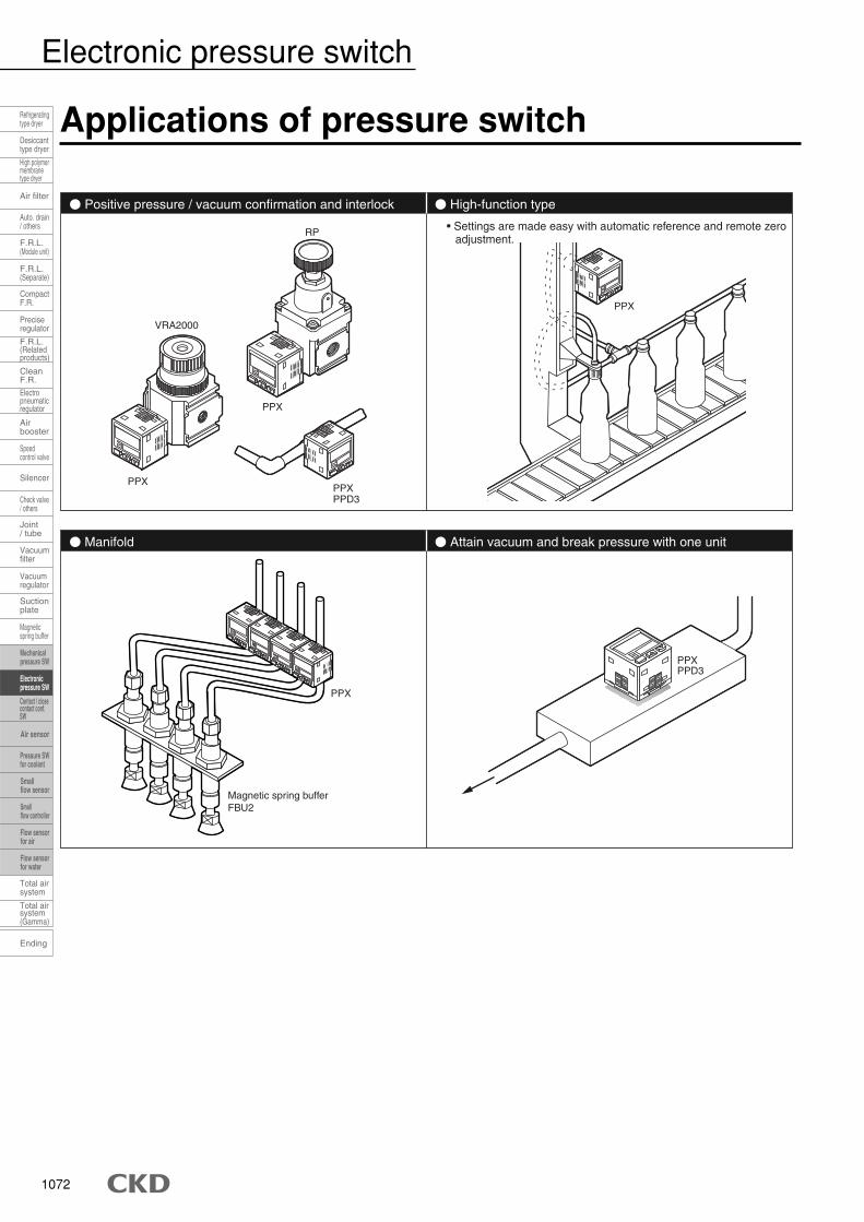
Applications of pressure switch
� Positive pressure / vacuum confirmation and interlock � High-function type
� Manifold � Attain vacuum and break pressure with one unit
PPXPPD3
PPX
PPX
VRA2000
RP
PPX
Magnetic spring bufferFBU2
PPXPPD3
• Settings are made easy with automatic reference and remote zero adjustment.
PPX
Electronic pressure switch
1073
Mechanicalpressure SW
Electronicpressure SW
Pressure SWfor coolant
Smallflow sensor
Smallflow controller
Flow sensorfor air
Flow sensorfor water
Air sensor
Ele
ctro
nic
pres
sure
sw
itch
Pre
ssur
e se
nsor
Speedcontrol valve
Check valve/ others
Magneticspring buffer
Contact / closecontact conf.SW
Refrigeratingtype dryer
Desiccanttype dryer
High polymermembranetype dryer
Auto. drain/ others
F.R.L.(Module unit)
F.R.L.(Separate)
F.R.L.(Relatedproducts)
CleanF.R.
Airbooster
Joint/ tube
Suctionplate
Total airsystem
Total airsystem(Gamma)
Air filter
CompactF.R.
Preciseregulator
Electropneumaticregulator
Silencer
Vacuumregulator
Ending
Vacuumfilter
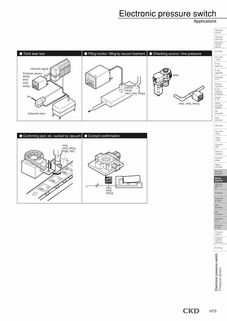
� Tank leak test � Checking source / line pressure
� Confirming part, etc. sucked by vacuum � Contact confirmation
� Filling monitor / filling by vacuum treatment
PPS2PPX, PPD, PPD3
Pressuresensor
PPX, PPD, PPD3
PPD
PPX, PPD, PPD3,PSW, PPE
PPXPPDPPD3
Interlock signal
Pressure sensorPPS2PPXPPDPPD3
Air
Solenoid valve
Electronic pressure switchApplications
1074
Ending
Speedcontrol valve
Check valve/ others
Magneticspring buffer
Refrigeratingtype dryer
Desiccanttype dryer
High polymermembranetype dryer
Auto. drain/ others
F.R.L.(Module unit)
F.R.L.(Separate)
F.R.L.(Relatedproducts)
CleanF.R.
Airbooster
Joint/ tube
Suctionplate
Total airsystem
Total airsystem(Gamma)
Air filter
CompactF.R.
Preciseregulator
Electropneumaticregulator
Silencer
Vacuumregulator
Vacuumfilter
Contact / closecontact conf.SW
Mechanicalpressure SW
Electronicpressure SW
Pressure SWfor coolant
Smallflow sensor
Smallflow controller
Flow sensorfor air
Flow sensorfor water
Air sensor
Pneumatic components (electronic pressure switch and sensor)
Safety precautionsAlways read this section before starting use.Refer to Intro 67 for general precautions, and to " Safety precautions" in this section fordetails on each series.
� Use this product in accordance of specifications.� Use for applications, or at load currents, voltages, tem-
peratures, impacts or sites excluded from the specifica-tions could result in damage or malfunctions.
� Do not use oxygen, corrosive or combustible gas,or toxic fluid for this product.
� Do not use this product in flammable atmosphere.� The pressure switch does not have an explosive-proof
structure. Never use in an explosive gas environment asexplosions or fires could result.
� Avoid installing this product in a sealed control boxor indoors.� If the fluid should leak due to any trouble, the pressure in
the sealed chamber could change and recreate a haz-ardous state. Use this product in the control box havingsafety device to control internal pressure, or indoors withno pressure differential from the outside.
� Power voltageUse the product within the specified power voltage range.The product could rupture or burn if voltage exceeding theworking range is applied or if an AC power supply (100 VAC)is applied.
� Load short circuitDo not short-circuit the load. Failure to observe this couldresult in rupture or burning.
� Incorrect wiringAvoid incorrect wiring such as wrong polarity of power source,etc. Failure to observe this could result in rupture or burning.
Design & Selection
WARNING � Working environment� Avoid using this product where vibration or impact ex-
ceeding 100m/s2 could be applied.� Check the temperature of fluid being measured and the
environmental temperature in piping.� When using a type that does not have the corresponding
protective structure, do not use for applications in whichwater or oil could be applied.
� Determine the setting taking error caused by accuracyand temperature characteristics into consideration.
� Take care when using this product for an interlockcircuit.� When using the pressure switch for an interlock signal
required high reliability, provide a double interlock by in-stalling a mechanical protection function or a switch (sen-sor) other than a pressure switch as a guard if problemsoccur. Execute inspection regularly to check that the nor-mal operation is done.
(Recommended value)
� Response is affected by working pressure and loadvolume. If repeatability with stable responsivenessis required, install a regulator in the proceedingstage.
� Take the following countermeasures to prevent mal-function caused by noise.� Insert a line filter in the AC power supply line.� Do not share power with an inverter or components caus-
ing motor noise, etc.� Use a surge suppressor, such as a CR or diode on the
inductive load (solenoid valve, relay, etc.), and removenoise where generated.
� When using a device such as a switching regulator or in-verter motor that could generate noise near the sensor, besure to ground the device frame ground (F.G.) terminal.
� Separate wiring to the sensors from strong magnetic fields.� Connect wiring to sensors with a shield wire.� Ground the shield wire on the power supply side.
� When the secondary side control pressure is re-leased to atmosphere as air blow, pressure may fluc-tuate depended on piping and blow conditions. Ex-ecute a test under actual working conditions or con-tact to CKD.
� Select the product whose flow is not less than thetotal of that used for sensors when selecting a dryer,an air filter, an oil mist filter and a regulator.
Model Protective structure
PPX/PPD/PPD-S
PPE(-A)/PPD3(-S)
PPS2 front controls (option)
PPD-A/PPS2 sensor's separate sensor section only
IP40
IP65
IP66
IP67
� Working fluidWhen using working fluid other than air; nitrogen gas, etc.,oxygen deficiency could be caused. Observe the followinginstructions.� Use this product in well ventilated locations.� Ventilate the work area when nitrogen gas is being used.� Inspect piping regularly, so nitrogen gas piping does not
leak.� Non-corrosive gas means substances such as nitrogen
or carbon dioxide contained in air and inert gases suchas argon or neon.
� When using this product for compressed air containingwater or oil, use the PPD(3)-S (stainless steel diaphragmsensor specifications) with increased corrosion resistance.
� If this product is used for vacuum suction confirma-tion, care must be taken for following matters.� When applying positive pressure for vacuum break onto
the product, check that it does not exceed the specifiedwithstand pressure.
CAUTION
1075
Mechanicalpressure SW
Electronicpressure SW
Pressure SWfor coolant
Smallflow sensor
Smallflow controller
Flow sensorfor air
Flow sensorfor water
Air sensor
Ele
ctro
nic
pres
sure
sw
itch
Pre
ssur
e se
nsor
Speedcontrol valve
Check valve/ others
Magneticspring buffer
Contact / closecontact conf.SW
Refrigeratingtype dryer
Desiccanttype dryer
High polymermembranetype dryer
Auto. drain/ others
F.R.L.(Module unit)
F.R.L.(Separate)
F.R.L.(Relatedproducts)
CleanF.R.
Airbooster
Joint/ tube
Suctionplate
Total airsystem
Total airsystem(Gamma)
Air filter
CompactF.R.
Preciseregulator
Electropneumaticregulator
Silencer
Vacuumregulator
Ending
Vacuumfilter
� Avoid incorrect connection.� An incorrect connection may cause a fatal error not only
to this product but also peripheral devices.
� DC power not insulated from AC primary side maydamage the product and power, so an electric shockcould occur. Do not use the product in this case.
Installation & Adjustment
WARNING
� Do not use the product where the product is ex-posed to direct-sunlight or may come in contact withwater or oil.
� Flash air pipe connected to sensors before connect-ing. Prevent pipe from catching tips of sealing tapewhen piping.
� Correct pressure control is not possible if the ex-haust port is plugged. Release this port into the at-mosphere.
� Apply adequate torque when connecting pipes.� To prevent air leakage and screw damage.� First tighten the screw by hand to prevent damage to screw
threads, then use a tool.
� Care must be taken for protection of body and lead wire.� Do not bump or drop the main unit, or apply excessive
bending or tensile strength to the lead because the leadcould be disconnected.
� Connect and wire bending-resistant material, such as ro-bot wire material, for the movable sections.
� Wiring� Turn power OFF before wiring this product. Discharge
static electricity charged in human body, tool or equip-ment before and during operation.
� Use a stabilized noise-free power supply with a ripplevoltage of 1% or less.
CAUTION
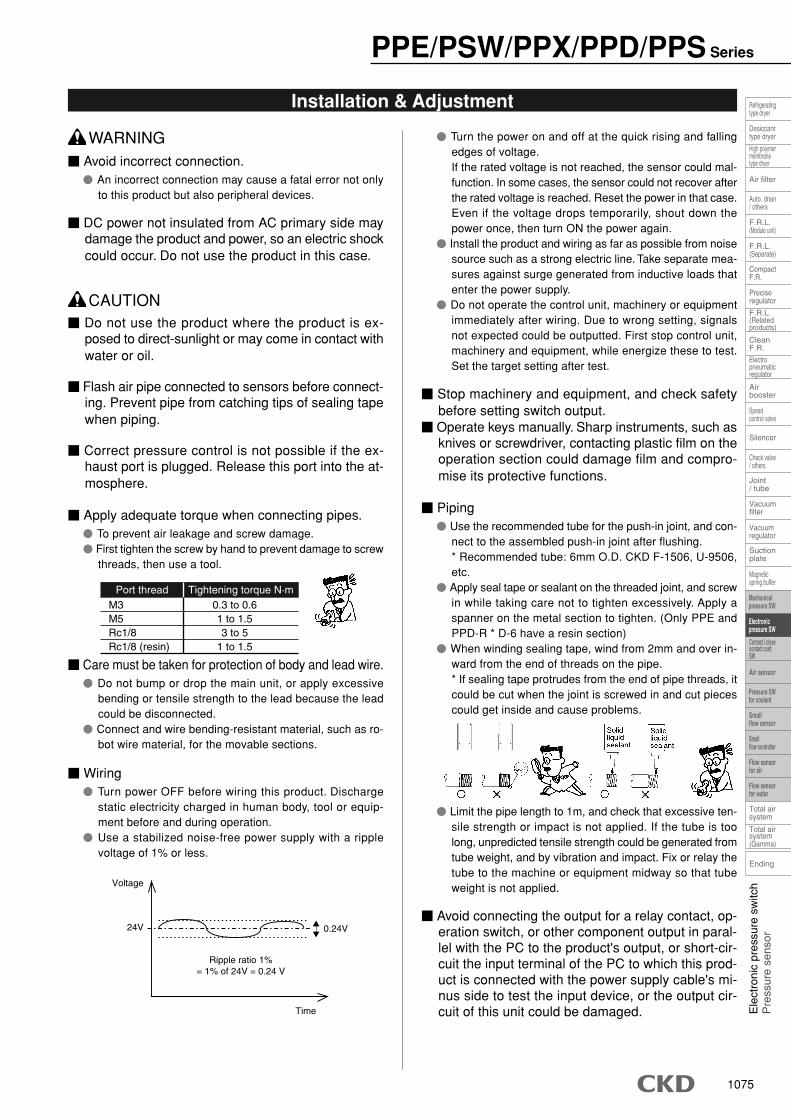
Port thread Tightening torque N·mM3M5Rc1/8Rc1/8 (resin)
0.3 to 0.61 to 1.53 to 5
1 to 1.5
0.24V
Time
Ripple ratio 1%= 1% of 24V = 0.24 V
Voltage
24V
� Turn the power on and off at the quick rising and fallingedges of voltage.If the rated voltage is not reached, the sensor could mal-function. In some cases, the sensor could not recover afterthe rated voltage is reached. Reset the power in that case.Even if the voltage drops temporarily, shout down thepower once, then turn ON the power again.
� Install the product and wiring as far as possible from noisesource such as a strong electric line. Take separate mea-sures against surge generated from inductive loads thatenter the power supply.
� Do not operate the control unit, machinery or equipmentimmediately after wiring. Due to wrong setting, signalsnot expected could be outputted. First stop control unit,machinery and equipment, while energize these to test.Set the target setting after test.
� Stop machinery and equipment, and check safetybefore setting switch output.
� Operate keys manually. Sharp instruments, such asknives or screwdriver, contacting plastic film on theoperation section could damage film and compro-mise its protective functions.
� Piping� Use the recommended tube for the push-in joint, and con-
nect to the assembled push-in joint after flushing.* Recommended tube: 6mm O.D. CKD F-1506, U-9506,etc.
� Apply seal tape or sealant on the threaded joint, and screwin while taking care not to tighten excessively. Apply aspanner on the metal section to tighten. (Only PPE andPPD-R * D-6 have a resin section)
� When winding sealing tape, wind from 2mm and over in-ward from the end of threads on the pipe.* If sealing tape protrudes from the end of pipe threads, itcould be cut when the joint is screwed in and cut piecescould get inside and cause problems.
� Limit the pipe length to 1m, and check that excessive ten-sile strength or impact is not applied. If the tube is toolong, unpredicted tensile strength could be generated fromtube weight, and by vibration and impact. Fix or relay thetube to the machine or equipment midway so that tubeweight is not applied.
� Avoid connecting the output for a relay contact, op-eration switch, or other component output in paral-lel with the PC to the product's output, or short-cir-cuit the input terminal of the PC to which this prod-uct is connected with the power supply cable's mi-nus side to test the input device, or the output cir-cuit of this unit could be damaged.
PPE/PSW/PPX/PPD/PPS Series

1076
Ending
Speedcontrol valve
Check valve/ others
Magneticspring buffer
Refrigeratingtype dryer
Desiccanttype dryer
High polymermembranetype dryer
Auto. drain/ others
F.R.L.(Module unit)
F.R.L.(Separate)
F.R.L.(Relatedproducts)
CleanF.R.
Airbooster
Joint/ tube
Suctionplate
Total airsystem
Total airsystem(Gamma)
Air filter
CompactF.R.
Preciseregulator
Electropneumaticregulator
Silencer
Vacuumregulator
Vacuumfilter
Contact / closecontact conf.SW
Mechanicalpressure SW
Electronicpressure SW
Pressure SWfor coolant
Smallflow sensor
Smallflow controller
Flow sensorfor air
Flow sensorfor water
Air sensor
� Care must be taken for disconnection and reversecurrent caused by wiring resistance.When other devices, including pressure switches,are connected to the same power supply as thepressure switch, and the output cable and powercable's minus side are short-circuited or the powersupply's minus side is disconnected to check op-eration of the input device from the control panel,reverse current could flow to the pressure switch'soutput circuit and cause damage.
Take countermeasures as followings to prevent dam-ages caused by reverse current.(1) Avoid centralizing current at the power cable, especially
the minus side power cable, and use as thick as possible.(2) Limit the number of devices connected to the same power
supply as the pressure switch.(3) Insert a diode in serial with the pressure switch's output
cable to prevent reversal of current.(4) Insert a diode in serial with the pressure switch's power
cable minus side to prevent reversal of current.
� Care must be taken for surge current leading.When the power is shared with inductive loads thatcreate surge current such as pressure switches,solenoid valves or relays, if the circuit is closed withinductive loads activated, surge current could leadto the output circuit, causing damages.
Current fromother device
Test SWor short circuitDisconnection
Pressure switch Control panelDiode to prevent
reverse flow
PLC
inpu
t
Mai
nci
rcui
t
Othe
r dev
ice
Pressure switch
Surge current PLC output
PC
ON
Rel
ay Solenoidvalve
Mai
nci
rcui
t
Circuit cutoff withdisconnection oremergency stop oremergency stop
Surgeabsorbingelement(Integrated)
Surgeabsorbingelement(installed later)
� Some models have a push in joint for the measuredpressure port. Check the perpendicularity of the tubeside, and check that there are no scratches, indents,or dirt near the end. Air and compressed air are mea-sured. Check that water and dirt do not enter thetube during piping.
Installation & Adjustment
CAUTION
� Do not apply overcurrent.� If overcurrent flows to the pressure switch because of
aload short circuit, etc., the pressure switch will be dam-aged and could also ignite. Provide an overcurrent pro-tection circuit, such as a fuse, for the output wire and powercable.
During Use & Maintenance
WARNING
� Do not disassemble the products.� The product could be damaged or performance compro-
mised if this product is disassembled. CKD does not guar-antee performance after disassembly. Remove the entireinstallation section (pressurized port section) when replac-ing or moving this product.
� With the PPD-*-IF-* type, the case must be removed dur-ing initial assembly. Take special care in handling. (Besure to follow assembly methods and precautions givenin the instruction manual enclosed with the product.)
� Stop machinery and equipment, then check thesafety before operating the product.
� With PPD/PPD3/PPS2, pressure is detected 200times per second, but this display is updated 4 timesa second, and cannot track fast pressure changes.The switch could therefore start operating at quicklychanging pressure even when the display does notindicate the switch setting.
� The case is made of resin. Do not use solvent, alco-hol, or detergent in cleaning, or resin could absorbit. Wipe contaminations with a well wrung rag, etc.,after soaked in weakened neutral detergent.
CAUTION
PPE/PSW/PPX/PPD/PPS Series
1077
Mechanicalpressure SW
Electronicpressure SW
Pressure SWfor coolant
Smallflow sensor
Smallflow controller
Flow sensorfor air
Flow sensorfor water
Air sensor
Ele
ctro
nic
pres
sure
sw
itch
Pre
ssur
e se
nsor
Speedcontrol valve
Check valve/ others
Magneticspring buffer
Contact / closecontact conf.SW
Refrigeratingtype dryer
Desiccanttype dryer
High polymermembranetype dryer
Auto. drain/ others
F.R.L.(Module unit)
F.R.L.(Separate)
F.R.L.(Relatedproducts)
CleanF.R.
Airbooster
Joint/ tube
Suctionplate
Total airsystem
Total airsystem(Gamma)
Air filter
CompactF.R.
Preciseregulator
Electropneumaticregulator
Silencer
Vacuumregulator
Ending
Vacuumfilter
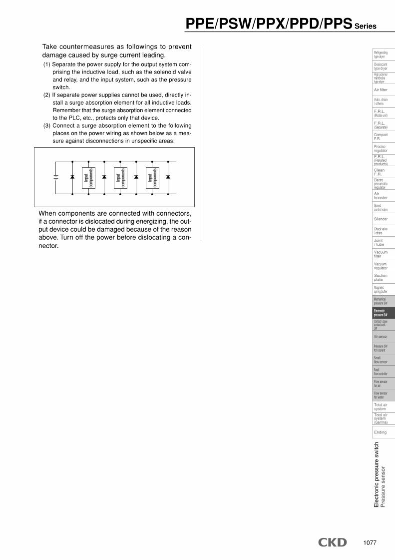
Take countermeasures as followings to preventdamage caused by surge current leading.(1) Separate the power supply for the output system com-
prising the inductive load, such as the solenoid valveand relay, and the input system, such as the pressureswitch.
(2) If separate power supplies cannot be used, directly in-stall a surge absorption element for all inductive loads.Remember that the surge absorption element connectedto the PLC, etc., protects only that device.
(3) Connect a surge absorption element to the followingplaces on the power wiring as shown below as a mea-sure against disconnections in unspecific areas:
When components are connected with connectors,if a connector is dislocated during energizing, the out-put device could be damaged because of the reasonabove. Turn off the power before dislocating a con-nector.
Inpu
tco
mpo
nent
s
Inpu
tco
mpo
nent
s
Inpu
tco
mpo
nent
s
PPE/PSW/PPX/PPD/PPS Series
1083
Mechanicalpressure SW
Electronicpressure SW
Pressure SWfor coolant
Smallflow sensor
Smallflow controller
Flow sensorfor air
Flow sensorfor water
Air sensor
Ele
ctro
nic
pres
sure
sw
itch
Pre
ssur
e se
nsor
Speedcontrol valve
Check valve/ others
Magneticspring buffer
Contact / closecontact conf.SW
Refrigeratingtype dryer
Desiccanttype dryer
High polymermembranetype dryer
Auto. drain/ others
F.R.L.(Module unit)
F.R.L.(Separate)
F.R.L.(Relatedproducts)
CleanF.R.
Airbooster
Joint/ tube
Suctionplate
Total airsystem
Total airsystem(Gamma)
Air filter
CompactF.R.
Preciseregulator
Electropneumaticregulator
Silencer
Vacuumregulator
Ending
Vacuumfilter
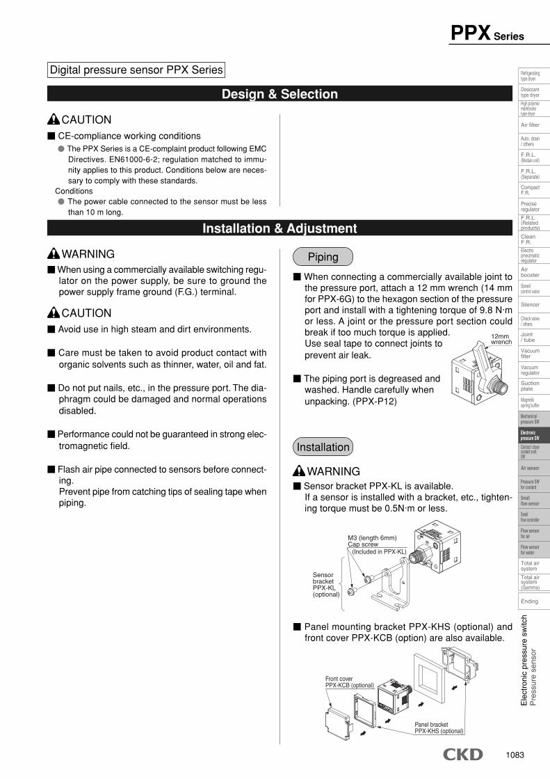
� Sensor bracket PPX-KL is available.If a sensor is installed with a bracket, etc., tighten-ing torque must be 0.5N·m or less.
� Panel mounting bracket PPX-KHS (optional) andfront cover PPX-KCB (option) are also available.
PPX Series
Digital pressure sensor PPX Series
� CE-compliance working conditions� The PPX Series is a CE-complaint product following EMC
Directives. EN61000-6-2; regulation matched to immu-nity applies to this product. Conditions below are neces-sary to comply with these standards.
Conditions� The power cable connected to the sensor must be less
than 10 m long.
Design & Selection
CAUTION
� When using a commercially available switching regu-lator on the power supply, be sure to ground thepower supply frame ground (F.G.) terminal.
Installation & Adjustment
WARNING
� Avoid use in high steam and dirt environments.
� Care must be taken to avoid product contact withorganic solvents such as thinner, water, oil and fat.
� Do not put nails, etc., in the pressure port. The dia-phragm could be damaged and normal operationsdisabled.
� Performance could not be guaranteed in strong elec-tromagnetic field.
� Flash air pipe connected to sensors before connect-ing.Prevent pipe from catching tips of sealing tape whenpiping.
CAUTION
� When connecting a commercially available joint tothe pressure port, attach a 12 mm wrench (14 mmfor PPX-6G) to the hexagon section of the pressureport and install with a tightening torque of 9.8 N·mor less. A joint or the pressure port section couldbreak if too much torque is applied.Use seal tape to connect joints toprevent air leak.
� The piping port is degreased andwashed. Handle carefully whenunpacking. (PPX-P12)
Piping
12mmwrench
Installation
SensorbracketPPX-KL(optional)
M3 (length 6mm)Cap screw
(Included in PPX-KL)
Front coverPPX-KCB (optional)
Panel bracketPPX-KHS (optional)
WARNING
1084
Ending
Speedcontrol valve
Check valve/ others
Magneticspring buffer
Refrigeratingtype dryer
Desiccanttype dryer
High polymermembranetype dryer
Auto. drain/ others
F.R.L.(Module unit)
F.R.L.(Separate)
F.R.L.(Relatedproducts)
CleanF.R.
Airbooster
Joint/ tube
Suctionplate
Total airsystem
Total airsystem(Gamma)
Air filter
CompactF.R.
Preciseregulator
Electropneumaticregulator
Silencer
Vacuumregulator
Vacuumfilter
Contact / closecontact conf.SW
Mechanicalpressure SW
Electronicpressure SW
Pressure SWfor coolant
Smallflow sensor
Smallflow controller
Flow sensorfor air
Flow sensorfor water
Air sensor
PPX Series
Installation & Adjustment
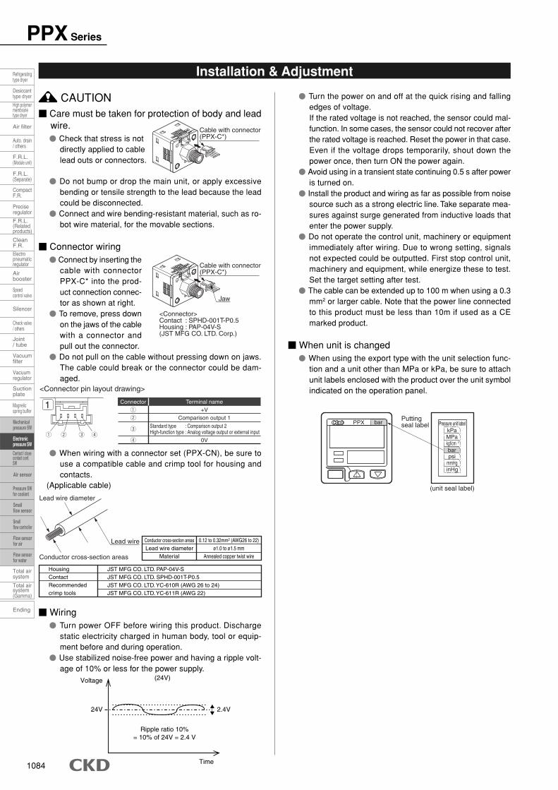
� Care must be taken for protection of body and leadwire.� Check that stress is not
directly applied to cablelead outs or connectors.
� Do not bump or drop the main unit, or apply excessivebending or tensile strength to the lead because the leadcould be disconnected.
� Connect and wire bending-resistant material, such as ro-bot wire material, for the movable sections.
� Connector wiring� Connect by inserting the
cable with connectorPPX-C* into the prod-uct connection connec-tor as shown at right.
� To remove, press downon the jaws of the cablewith a connector andpull out the connector.
� Do not pull on the cable without pressing down on jaws.The cable could break or the connector could be dam-aged.
� When wiring with a connector set (PPX-CN), be sure touse a compatible cable and crimp tool for housing andcontacts.
(Applicable cable)
� Wiring� Turn power OFF before wiring this product. Discharge
static electricity charged in human body, tool or equip-ment before and during operation.
� Use stabilized noise-free power and having a ripple volt-age of 10% or less for the power supply.
(24V)
2.4V
Time
Ripple ratio 10%= 10% of 24V = 2.4 V
Voltage
24V
CAUTION
Cable with connector(PPX-C*)
<Connector>Contact : SPHD-001T-P0.5Housing : PAP-04V-S(JST MFG CO. LTD. Corp.)
Cable with connector(PPX-C*)
Jaw
1 2 3 4
1
<Connector pin layout drawing>
Connector+V1
Comparison output 12
3
0V4
Standard type : Comparison output 2High-function type : Analog voltage output or external input
Terminal name
Conductor cross-section areasLead wire diameter
Material
0.12 to 0.32mm2 (AWG26 to 22)ø1.0 to ø1.5 mm
Annealed copper twist wire
HousingContactRecommended crimp tools
JST MFG CO. LTD. PAP-04V-SJST MFG CO. LTD. SPHD-001T-P0.5JST MFG CO. LTD. YC-610R (AWG 26 to 24)JST MFG CO. LTD. YC-611R (AWG 22)
Lead wire diameter
Lead wire
Conductor cross-section areas
bar
bar
mmHginHg
psi
kgf/cmMPakPa
3
Puttingseal label
(unit seal label)
Pressure unit labelPPX
� Turn the power on and off at the quick rising and fallingedges of voltage.If the rated voltage is not reached, the sensor could mal-function. In some cases, the sensor could not recover afterthe rated voltage is reached. Reset the power in that case.Even if the voltage drops temporarily, shout down thepower once, then turn ON the power again.
� Avoid using in a transient state continuing 0.5 s after poweris turned on.
� Install the product and wiring as far as possible from noisesource such as a strong electric line. Take separate mea-sures against surge generated from inductive loads thatenter the power supply.
� Do not operate the control unit, machinery or equipmentimmediately after wiring. Due to wrong setting, signalsnot expected could be outputted. First stop control unit,machinery and equipment, while energize these to test.Set the target setting after test.
� The cable can be extended up to 100 m when using a 0.3mm2 or larger cable. Note that the power line connectedto this product must be less than 10m if used as a CEmarked product.
� When unit is changed� When using the export type with the unit selection func-
tion and a unit other than MPa or kPa, be sure to attachunit labels enclosed with the product over the unit symbolindicated on the operation panel.
1098 1099
( )
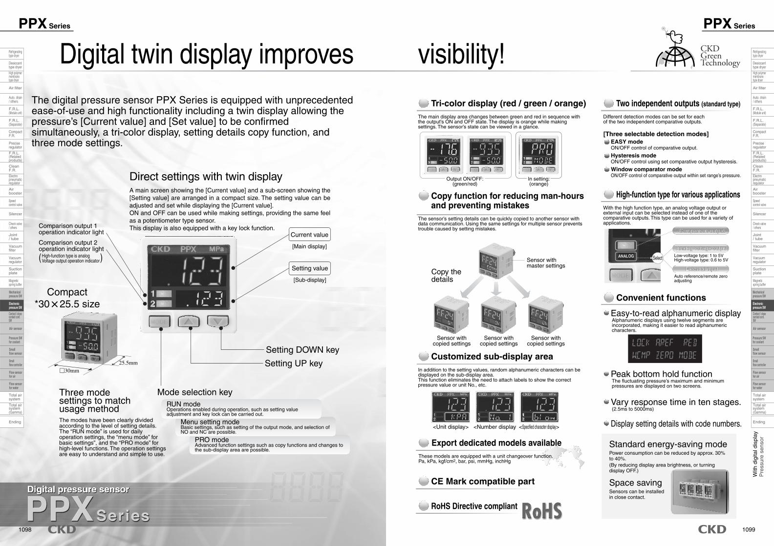
Digital twin display improves visibility!The digital pressure sensor PPX Series is equipped with unprecedented ease-of-use and high functionality including a twin display allowing the pressure’s [Current value] and [Set value] to be confirmed simultaneously, a tri-color display, setting details copy function, and three mode settings.
A main screen showing the [Current value] and a sub-screen showing the [Setting value] are arranged in a compact size. The setting value can be adjusted and set while displaying the [Current value]. ON and OFF can be used while making settings, providing the same feel as a potentiometer type sensor. This display is also equipped with a key lock function.
Direct settings with twin display
Comparison output 2operation indicator light
High-function type is analogVoltage output operation indicator
Comparison output 1operation indicator light Current value
Tri-color display (red / green / orange) Two independent outputs (standard type)
High-function type for various applications
Convenient functions
Comparison output
Analog voltage output
External input
Standard energy-saving mode
Peak bottom hold function
Easy-to-read alphanumeric display
Vary response time in ten stages.
Display setting details with code numbers.
Space saving
Copy function for reducing man-hoursand preventing mistakes
Customized sub-display area
Export dedicated models available
CE Mark compatible part
RoHS Directive compliant
Setting value
Setting DOWN key
Setting UP key
Mode selection keyRUN modeOperations enabled during operation, such as setting valueadjustment and key lock can be carried out.
Menu setting modeBasic settings, such as setting of the output mode, and selection ofNO and NC are possible.
PRO modeAdvanced function settings such as copy functions and changes tothe sub-display area are possible.
25.5mm
Compact*30�25.5 size
�30mm
[Main display]
[Sub-display]
Three modesettings to matchusage methodThe modes have been clearly divided according to the level of setting details. The “RUN mode” is used for daily operation settings, the “menu mode” for basic settings”, and the “PRO mode” for high-level functions. The operation settings are easy to understand and simple to use.
The main display area changes between green and red in sequence with the output’s ON and OFF state. The display is orange while making settings. The sensor’s state can be viewed in a glance.
Power consumption can be reduced by approx. 30% to 40%.(By reducing display area brightness, or turning display OFF.)
Sensors can be installed in close contact.
Different detection modes can be set for eachof the two independent comparative outputs.
With the high function type, an analog voltage output or external input can be selected instead of one of the comparative outputs. This type can be used for a variety of applications.
Alphanumeric displays using twelve segments are incorporated, making it easier to read alphanumeric characters.
The fluctuating pressure’s maximum and minimum pressures are displayed on two screens.
(2.5ms to 5000ms)
In addition to the setting values, random alphanumeric characters can be displayed on the sub-display area. This function eliminates the need to attach labels to show the correct pressure value or unit No., etc.
These models are equipped with a unit changeover function.Pa, kPa, kgf/cm2, bar, psi, mmHg, inchHg
The sensor’s setting details can be quickly copied to another sensor with data communication. Using the same settings for multiple sensor prevents trouble caused by setting mistakes.
Output ON/OFF:(green/red)
In setting:(orange)
Sensor withmaster settings
Copy thedetails
Sensor withcopied settings
<Unit display> <Number display <Specified character display>
Sensor withcopied settings
Sensor withcopied settings
Comparison output
Analog voltage output
Select
External input
Low-voltage type: 1 to 5VHigh-voltage type: 0.6 to 5V
Auto reference/remote zeroadjusting
EASY mode[Three selectable detection modes]
Hysteresis mode
Window comparator mode
ON/OFF control of comparative output.
ON/OFF control using set comparative output hysteresis.
ON/OFF control of comparative output within set range’s pressure.
Ending
Speedcontrol valve
Check valve/ others
Magneticspring buffer
Refrigeratingtype dryer
Desiccanttype dryer
High polymermembranetype dryer
Auto. drain/ others
F.R.L.(Module unit)
F.R.L.(Separate)
F.R.L.(Relatedproducts)
CleanF.R.
Airbooster
Joint/ tube
Suctionplate
Total airsystem
Total airsystem(Gamma)
Air filter
CompactF.R.
Preciseregulator
Electropneumaticregulator
Silencer
Vacuumregulator
Vacuumfilter
Contact / closecontact conf.SW
Mechanicalpressure SW
Electronicpressure SW
Pressure SWfor coolant
Smallflow sensor
Smallflow controller
Flow sensorfor air
Flow sensorfor water
Air sensor
PPX Series
1098
With
dig
ital d
ispl
ayP
ress
ure
sens
or
Speedcontrol valve
Check valve/ others
Magneticspring buffer
Mechanicalpressure SW
Electronicpressure SW
Pressure SWfor coolant
Smallflow sensor
Smallflow controller
Flow sensorfor air
Flow sensorfor water
Air sensor
Contact / closecontact conf.SW
Refrigeratingtype dryer
Desiccanttype dryer
High polymermembranetype dryer
Auto. drain/ others
F.R.L.(Module unit)
F.R.L.(Separate)
F.R.L.(Relatedproducts)
CleanF.R.
Airbooster
Joint/ tube
Suctionplate
Total airsystem
Total airsystem(Gamma)
Air filter
CompactF.R.
Preciseregulator
Electropneumaticregulator
Silencer
Vacuumregulator
Ending
Vacuumfilter
PPX Series

1100
Digital pressure sensor
PPX Series
JIS symbol
Diffused semiconductor pressure sensor
Air/non-corrosive gas
Gauge pressure
Compatible only with export models (-KA) (MPa, kPa, kgf/cm2, bar, psi, mmHg, inchHg)
4-digit + 4-digit tri-color LCD display (display update cycle: 250 ms, 1000 ms, select with key operations)
12 to 24 VDC±10% ripple P-P10% or less
Normal: 840mW or less (current consumption 35mA or less at 24 V power)
ECO mode: 600mW of less at STD (currant consumption 25mA or less at power voltage 24V), 480mW or less at FULL (currant consumption 20mA or less at power voltage 24V)
Select NO/NC with the key operation
EASY MODE/hysteresis mode/window comparator mode
Min.1 digit (variable)
2.5ms, 5ms, 10ms, 25ms, 50ms, 100ms, 250ms, 500ms, 1000ms, 5000ms select by the key operation
Equipped
IP40 (IEC)
-10 to + 50 , at store: -10 to + 60˚C
35 to 85%RH (no dew condensation, freezing), store: 35 to 85%RH
1000 VAC for one minute applied to all charged sections/between cases
50MΩ and over with 500 VDC mega applied to all charged sections/between cases
Durability 10 to 500 Hz double amplitude 3 mm 2 hours each in XYZ directions (When mounted on panel: durability 10 to 150 Hz double amplitude width 0.75 mm 2 hours each in XYZ directions)
Durability 100 m/S2 (10 G) 3 times each in XYZ directions
Connector
M5 female thread + R (PT) 1/8 male thread
When wire is extended, up to 100 m permissible with 0.3 mm2 or larger cable (less than 10 m when CE Mark-compliant)
Product weight: approx. 40g, weight including package: 135g
PPX-C2 (2m cable with connector): 1 pc.Unit seal label (KA with unit change): MPa, kPa.kgf/cm2, bar, psi, mmHg, inchHg
-100.0 to +100.0kPa
-100.0 to +100.0kPa
kPa
0.1kPa
500kPa
±0.1%F.S. (within ±2 digits)
Within ±0.5%F.S.
(NPN output type)NPN transistor/open collector• Max. inrush current: 100mA• Applied voltage: 30 VDC or less (comparison output–0V interval)• Residual voltage: 2V or less (at inrush current 100mA)
(PNP output type)PNP transistor/open collector• Max. output current: 100mA• Applied voltage: 30 VDC or less (comparison output between – and +)• Residual voltage: 2V or less (at output current 100mA)
Orange LED(Comparison output 1 operational indicator light, comparison output 2
operational indicator light: comparison output ON lighting)
(NPN output type)ONVoltage: 0.4VDC or lessOFF voltage: 5 to 30 VDC or releaseInput impedance: 10kΩInput time: 1ms and over
Output voltage: 1 to 5VZero point: Within 3V 5%F.S.Span: Within 4V±5%F.S.Linearity: Within 1%F.S.Output impedance: 1kΩ
(PNP output type)ONVoltage: 5V to +VDCOFF voltage: 0.6 VDC or less or releaseInput impedance: 10kΩInput time: 1ms and over
Output voltage: 0.6 to 5VZero point: Within 1 V±5%F.S.Span: Within 4.4V±5%F.S.Linearity: Within 1%F.S.Output impedance: 1kΩ
-0.100 to +1.000MPa
-0.100 to +1.000MPa
MPa
0.001MPa
1.5MPa
±0.2%F.S.(within ±2 digits)
Within 1%F.S.
-100.0 to +100.0kPa
-100.0 to +100.0kPa
kPa
0.1kPa
500kPa
±0.1%F.S. (within ±2 digits)
Within ±0.5%F.S.
-0.100 to +1.000MPa
-0.100 to +1.000MPa
MPa
0.001MPa
1.5MPa
±0.2%F.S.(within ±2 digits)
Within 1%F.S.
Pressure sensitive element
Working fluid
Type of pressure
Rated pressure range
Set pressure range
Display unit
Minimum display unit
Unit change
Withstanding pressure
Repeatability
Temperature characteristics (+ 20˚C reference)
Indicator
Indicator light
Power voltage
Power consumption
Comparison output
(switch output)
External input
(auto reference/
remote zero adjusting)
Analog output
Connection
Port size Note 1
Wiring length
Weight
Accessory Note 2
Output operation
Output mode
Hysteresis
Response time
Short circuit protection
Protective structure
Ambient temperature
Ambient humidity
Withstanding voltage
Insulation resistance
Mechanical vibration proof
Mechanical shock proof
SpecificationsStandard type High-function type
Descriptions Low pressurePPX-R01*
High pressurePPX-R10*
Low pressurePPX-R01*H
High pressurePPX-R10*H
Note 1: See Table 1 on the next page for export use. Note 2: For (- J), connector cable is not attached.
Env
ironm
ent c
ondi
tions
Orange LED(Comparison output 1 operational indicator light: comparison output ON lighting,
analog voltage output operational indicator light: Lighting when setting)
Ending
Speedcontrol valve
Check valve/ others
Magneticspring buffer
Refrigeratingtype dryer
Desiccanttype dryer
High polymermembranetype dryer
Auto. drain/ others
F.R.L.(Module unit)
F.R.L.(Separate)
F.R.L.(Relatedproducts)
CleanF.R.
Airbooster
Joint/ tube
Suctionplate
Total airsystem
Total airsystem(Gamma)
Air filter
CompactF.R.
Preciseregulator
Electropneumaticregulator
Silencer
Vacuumregulator
Vacuumfilter
Contact / closecontact conf.SW
Mechanicalpressure SW
Electronicpressure SW
Pressure SWfor coolant
Smallflow sensor
Smallflow controller
Flow sensorfor air
Flow sensorfor water
Air sensor
1101
With
dig
ital d
ispl
ayP
ress
ure
sens
or
Speedcontrol valve
Check valve/ others
Magneticspring buffer
Mechanicalpressure SW
Electronicpressure SW
Pressure SWfor coolant
Smallflow sensor
Smallflow controller
Flow sensorfor air
Flow sensorfor water
Air sensor
Contact / closecontact conf.SW
Refrigeratingtype dryer
Desiccanttype dryer
High polymermembranetype dryer
Auto. drain/ others
F.R.L.(Module unit)
F.R.L.(Separate)
F.R.L.(Relatedproducts)
CleanF.R.
Airbooster
Joint/ tube
Suctionplate
Total airsystem
Total airsystem(Gamma)
Air filter
CompactF.R.
Preciseregulator
Electropneumaticregulator
Silencer
Vacuumregulator
Ending
Vacuumfilter
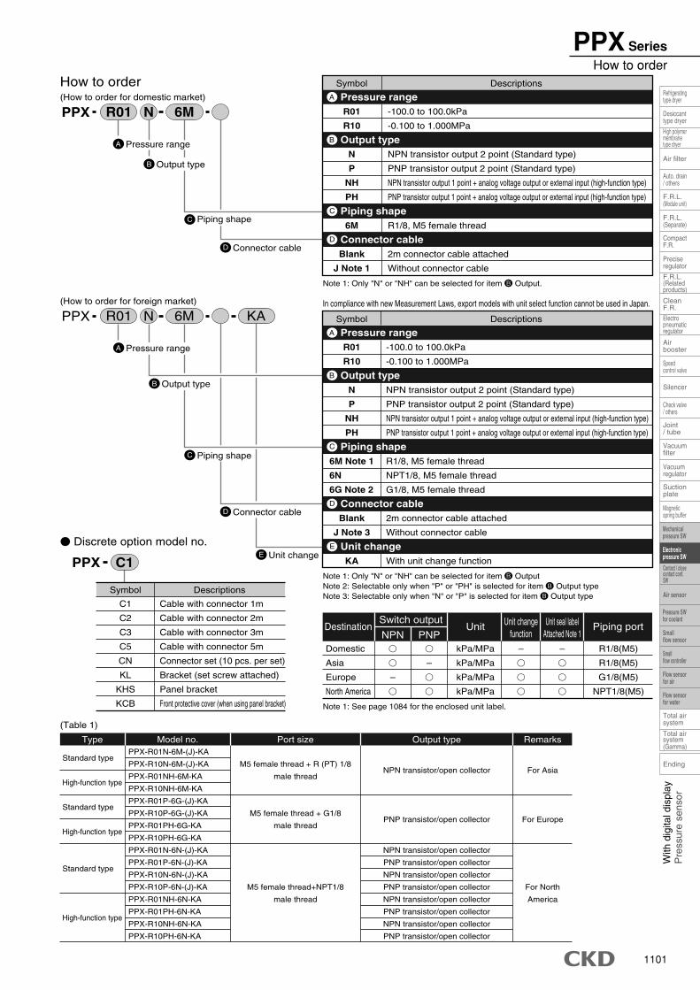
PPX SeriesHow to order
D Connector cable
B Output type
How to order(How to order for domestic market)
C Piping shape
D Connector cable
PPX R01 6MN
A Pressure range
B Output type
(How to order for foreign market)
C Piping shape
E Unit change
PPX R01 6M KAN
A
�
�
–
�
�
–
�
�
Domestic
Asia
Europe
North America
DestinationSwitch output
NPN PNP–
�
�
�
Unit changefunction
R1/8(M5)
R1/8(M5)
G1/8(M5)
NPT1/8(M5)
Piping port
–
�
�
�
Unit seal labelAttached Note 1
Symbol Descriptions
C1
C2
C3
C5
CN
KL
KHS
KCB
Cable with connector 1m
Cable with connector 2m
Cable with connector 3m
Cable with connector 5m
Connector set (10 pcs. per set)
Bracket (set screw attached)
Panel bracket
Front protective cover (when using panel bracket)
� Discrete option model no.
(Table 1)
C1PPX
Standard type
High-function type
Standard type
High-function type
Standard type
High-function type
PPX-R01N-6M-(J)-KA
PPX-R10N-6M-(J)-KA
PPX-R01NH-6M-KA
PPX-R10NH-6M-KA
PPX-R01P-6G-(J)-KA
PPX-R10P-6G-(J)-KA
PPX-R01PH-6G-KA
PPX-R10PH-6G-KA
PPX-R01N-6N-(J)-KA
PPX-R01P-6N-(J)-KA
PPX-R10N-6N-(J)-KA
PPX-R10P-6N-(J)-KA
PPX-R01NH-6N-KA
PPX-R01PH-6N-KA
PPX-R10NH-6N-KA
PPX-R10PH-6N-KA
M5 female thread + R (PT) 1/8
male thread
M5 female thread + G1/8
male thread
M5 female thread+NPT1/8
male thread
Type Model no. Port size
NPN transistor/open collector
PNP transistor/open collector
NPN transistor/open collector
PNP transistor/open collector
NPN transistor/open collector
PNP transistor/open collector
NPN transistor/open collector
PNP transistor/open collector
NPN transistor/open collector
PNP transistor/open collector
Output type
For Asia
For Europe
For North
America
Remarks
kPa/MPa
kPa/MPa
kPa/MPa
kPa/MPa
Unit
Pressure range
Symbol Descriptions
R01
R10
-100.0 to 100.0kPa
-0.100 to 1.000MPa
Pressure range A
N
P
NH
PH
NPN transistor output 2 point (Standard type)
PNP transistor output 2 point (Standard type)
NPN transistor output 1 point + analog voltage output or external input (high-function type)
PNP transistor output 1 point + analog voltage output or external input (high-function type)
Output typeB
6M R1/8, M5 female thread
Piping shapeC
Blank
J Note 1
2m connector cable attached
Without connector cable
Connector cableD
Note 1: Only "N" or "NH" can be selected for item B Output.
Symbol Descriptions
R01
R10
-100.0 to 100.0kPa
-0.100 to 1.000MPa
Pressure range A
N
P
NH
PH
NPN transistor output 2 point (Standard type)
PNP transistor output 2 point (Standard type)
NPN transistor output 1 point + analog voltage output or external input (high-function type)
PNP transistor output 1 point + analog voltage output or external input (high-function type)
Output typeB
6M Note 1
6N
6G Note 2
R1/8, M5 female thread
NPT1/8, M5 female thread
G1/8, M5 female thread
Piping shapeC
Blank
J Note 3
2m connector cable attached
Without connector cable
KA With unit change function
Connector cableD
Unit changeE
Note 1: Only "N" or "NH" can be selected for item B Output Note 2: Selectable only when "P" or "PH" is selected for item B Output type Note 3: Selectable only when "N" or "P" is selected for item B Output type
Note 1: See page 1084 for the enclosed unit label.
In compliance with new Measurement Laws, export models with unit select function cannot be used in Japan.
1102
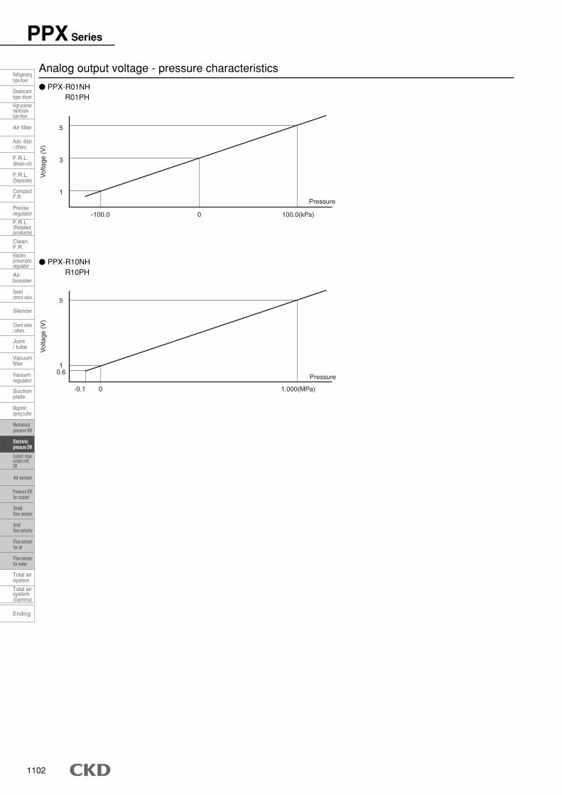
PPX Series
Analog output voltage - pressure characteristics
5
10.6
-0.1 0 1.000(MPa)
Pressure
Vol
tage
(V
)
5
1
-100.0 0 100.0(kPa)
Pressure
3
Vol
tage
(V
)
� PPX-R10NH R10PH
� PPX-R01NH R01PH
Ending
Speedcontrol valve
Check valve/ others
Magneticspring buffer
Refrigeratingtype dryer
Desiccanttype dryer
High polymermembranetype dryer
Auto. drain/ others
F.R.L.(Module unit)
F.R.L.(Separate)
F.R.L.(Relatedproducts)
CleanF.R.
Airbooster
Joint/ tube
Suctionplate
Total airsystem
Total airsystem(Gamma)
Air filter
CompactF.R.
Preciseregulator
Electropneumaticregulator
Silencer
Vacuumregulator
Vacuumfilter
Contact / closecontact conf.SW
Mechanicalpressure SW
Electronicpressure SW
Pressure SWfor coolant
Smallflow sensor
Smallflow controller
Flow sensorfor air
Flow sensorfor water
Air sensor
1103
With
dig
ital d
ispl
ayP
ress
ure
sens
or
Speedcontrol valve
Check valve/ others
Magneticspring buffer
Mechanicalpressure SW
Electronicpressure SW
Pressure SWfor coolant
Smallflow sensor
Smallflow controller
Flow sensorfor air
Flow sensorfor water
Air sensor
Contact / closecontact conf.SW
Refrigeratingtype dryer
Desiccanttype dryer
High polymermembranetype dryer
Auto. drain/ others
F.R.L.(Module unit)
F.R.L.(Separate)
F.R.L.(Relatedproducts)
CleanF.R.
Airbooster
Joint/ tube
Suctionplate
Total airsystem
Total airsystem(Gamma)
Air filter
CompactF.R.
Preciseregulator
Electropneumaticregulator
Silencer
Vacuumregulator
Ending
Vacuumfilter
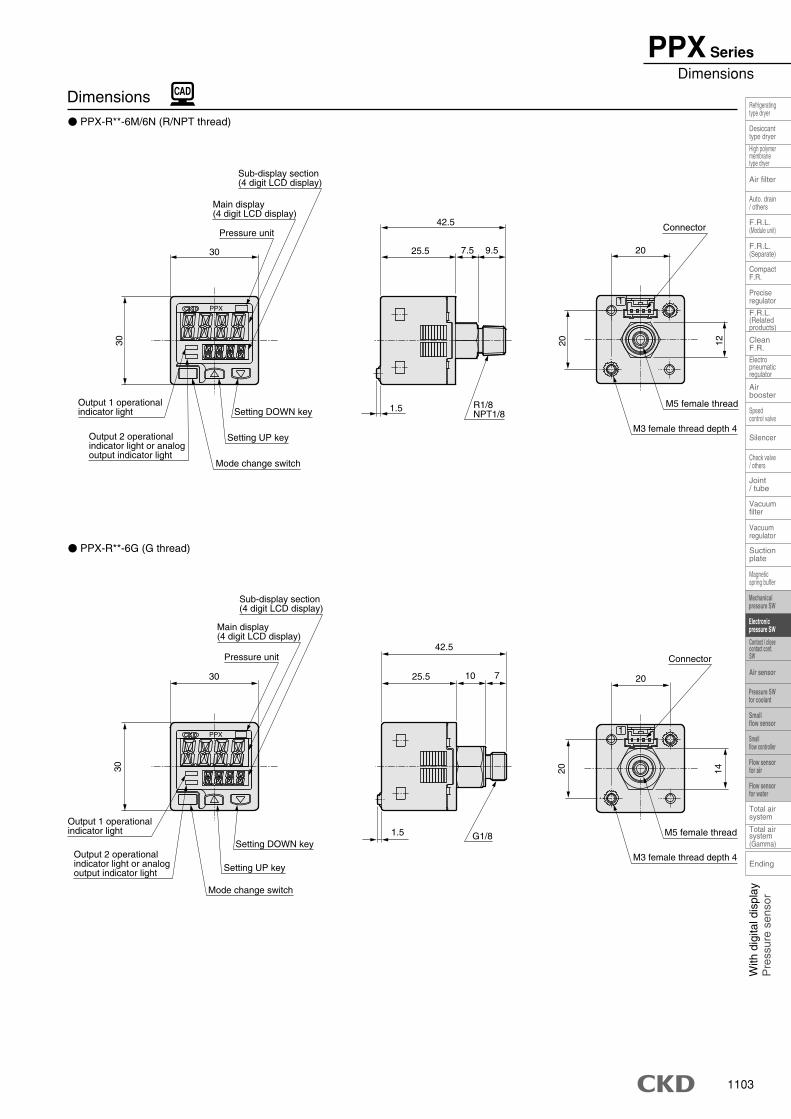
PPX SeriesDimensions
� PPX-R**-6M/6N (R/NPT thread)
� PPX-R**-6G (G thread)
Dimensions
1PPX
PPX 1
30 20
2030
7.525.5
42.5
1.5
12
9.5
M3 female thread depth 4
M5 female thread
Connector
Output 2 operationalindicator light or analogoutput indicator light
Setting DOWN key
Mode change switch
Setting UP key
Output 1 operationalindicator light
Pressure unit
Main display(4 digit LCD display)
Sub-display section(4 digit LCD display)
R1/8NPT1/8
14
20
20
30
30
25.5 710
42.5
1.5
Pressure unit
Main display(4 digit LCD display)
Setting DOWN key
Sub-display section(4 digit LCD display)
Output 1 operationalindicator light
Output 2 operationalindicator light or analogoutput indicator light
Mode change switch
Setting UP key
G1/8
Connector
M3 female thread depth 4
M5 female thread
1104
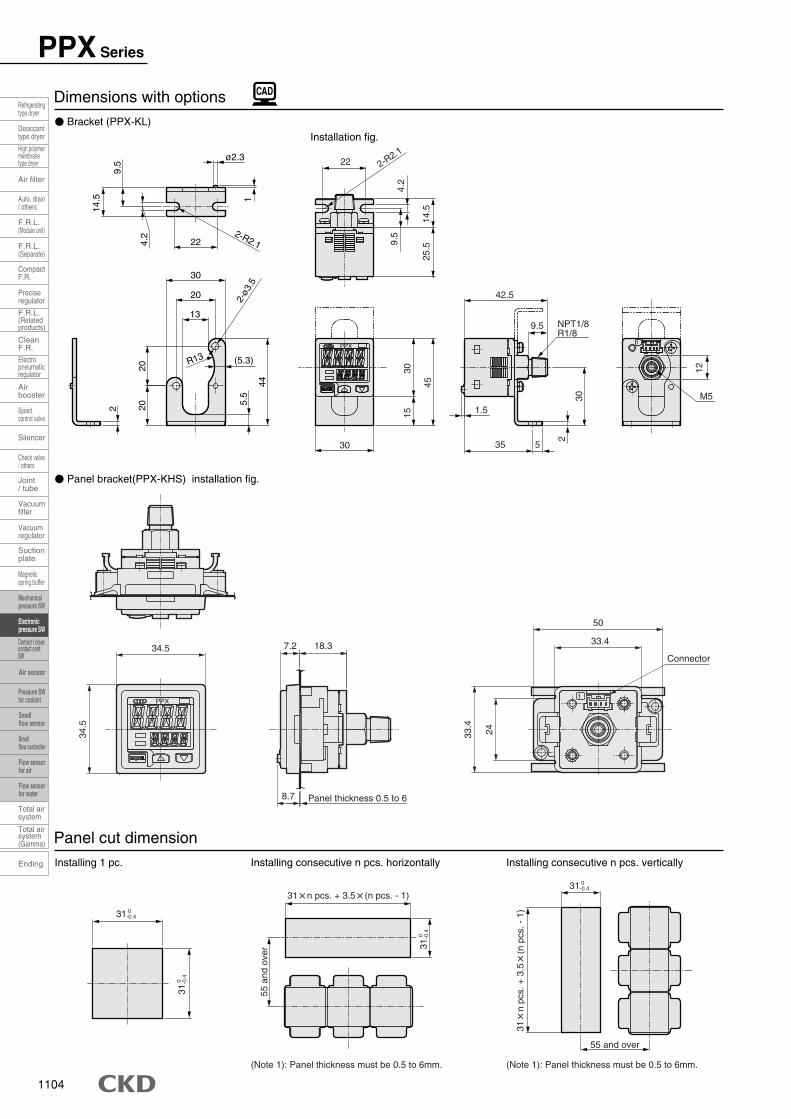
PPX Series
� Bracket (PPX-KL)Installation fig.
� Panel bracket(PPX-KHS) installation fig.
Dimensions with options
Installing 1 pc. Installing consecutive n pcs. horizontally Installing consecutive n pcs. vertically
Panel cut dimension
1
1
30 35
42.5
45
1530
1.5
25.5
14.5
4.2
9.5
30
2
5
22 2-R2.1
M5
12
NPT1/8R1/8
9.5
PPX
(Note 1): Panel thickness must be 0.5 to 6mm.(Note 1): Panel thickness must be 0.5 to 6mm.
ø2.3
4.2
22
R13
13
20
30
5.5
44
2-R2.11
2-ø3
.5
(5.3)
2 2020
9.5
14.5
34.5
2433.4
33.4
50
8.7
34.5 18.37.2Connector
PPX
Panel thickness 0.5 to 6
31 0 -0.4
31 0
-0.4
31 0
-0.4
55 a
nd o
ver
31�n pcs. + 3.5�(n pcs. - 1)31 0
-0.4
31�
n pc
s. +
3.5
�(n
pcs
. - 1
)
55 and over
Ending
Speedcontrol valve
Check valve/ others
Magneticspring buffer
Refrigeratingtype dryer
Desiccanttype dryer
High polymermembranetype dryer
Auto. drain/ others
F.R.L.(Module unit)
F.R.L.(Separate)
F.R.L.(Relatedproducts)
CleanF.R.
Airbooster
Joint/ tube
Suctionplate
Total airsystem
Total airsystem(Gamma)
Air filter
CompactF.R.
Preciseregulator
Electropneumaticregulator
Silencer
Vacuumregulator
Vacuumfilter
Contact / closecontact conf.SW
Mechanicalpressure SW
Electronicpressure SW
Pressure SWfor coolant
Smallflow sensor
Smallflow controller
Flow sensorfor air
Flow sensorfor water
Air sensor
1105
With
dig
ital d
ispl
ayP
ress
ure
sens
or
Speedcontrol valve
Check valve/ others
Magneticspring buffer
Mechanicalpressure SW
Electronicpressure SW
Pressure SWfor coolant
Smallflow sensor
Smallflow controller
Flow sensorfor air
Flow sensorfor water
Air sensor
Contact / closecontact conf.SW
Refrigeratingtype dryer
Desiccanttype dryer
High polymermembranetype dryer
Auto. drain/ others
F.R.L.(Module unit)
F.R.L.(Separate)
F.R.L.(Relatedproducts)
CleanF.R.
Airbooster
Joint/ tube
Suctionplate
Total airsystem
Total airsystem(Gamma)
Air filter
CompactF.R.
Preciseregulator
Electropneumaticregulator
Silencer
Vacuumregulator
Ending
Vacuumfilter
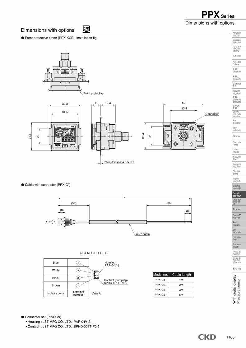
PPX SeriesDimensions with options
� Front protective cover (PPX-KCB) installation fig.
� Connector set (PPX-CN)• Housing : JST MFG CO. LTD. PAP-04V-S• Contact : JST MFG CO. LTD. SPHD-001T-P0.5
� Cable with connector (PPX-C*)
Dimensions with options
Model no. Cable length
PPX-C1
PPX-C2
PPX-C3
PPX-C5
1m
2m
3m
5m
PPX
A
Contact (crimping)SPHD-001T-P0.5
HousingPAP-04V-S
1
2
3
4
TerminalnumberIsolator color
Brown
Black
White
Blue
(JST MFG CO. LTD.)
View A
1
39.3
34.5
34.5
20
11 18.3
L
(8)
(35) (50)
(8)
ø3.7 cable
2433.4
33.4
50
Connector
Panel thickness 0.5 to 6
Front protective
1106
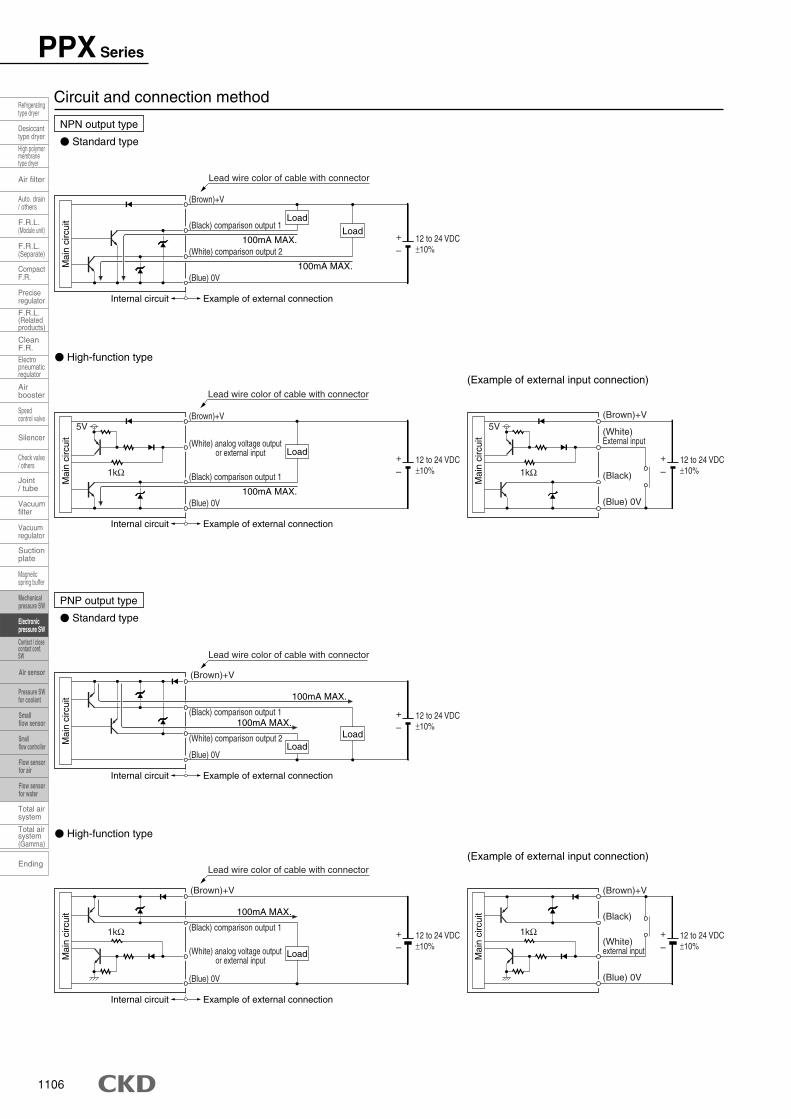
PPX Series
NPN output type
� Standard type
� High-function type
(Example of external input connection)
Circuit and connection method
PNP output type
� Standard type
� High-function type
(Example of external input connection)
(Black) comparison output 1
Example of external connectionInternal circuit
+
–12 to 24 VDC±10%
(Brown)+V
(Blue) 0V
(White) analog voltage outputor external input
1kΩ
100mA MAX.
Lead wire color of cable with connector
Example of external connectionInternal circuit
+
–12 to 24 VDC±10%
(Brown)+V
(Black) comparison output 1
(White) comparison output 2
(Blue) 0V100mA MAX.
100mA MAX.
Lead wire color of cable with connector
Example of external connectionInternal circuit
+
–12 to 24 VDC±10%
(Brown)+V
(White) analog voltage outputor external input
(Black) comparison output 1
(Blue) 0V100mA MAX.
5V
1kΩ
Lead wire color of cable with connector
(Black)
+
–12 to 24 VDC±10%
(Brown)+V
(Blue) 0V
(White)external input
1kΩ
+
–12 to 24 VDC±10%
(Brown)+V
(White)External input
(Black)
(Blue) 0V
5V
1kΩ
Example of external connectionInternal circuit
+
–12 to 24 VDC±10%
(Brown)+V
(Black) comparison output 1
(White) comparison output 2
(Blue) 0V
100mA MAX.
100mA MAX.
Lead wire color of cable with connector
Mai
n ci
rcui
tM
ain
circ
uit
Mai
n ci
rcui
tM
ain
circ
uit
Mai
n ci
rcui
tM
ain
circ
uit
LoadLoad
Load
LoadLoad
Load
Ending
Speedcontrol valve
Check valve/ others
Magneticspring buffer
Refrigeratingtype dryer
Desiccanttype dryer
High polymermembranetype dryer
Auto. drain/ others
F.R.L.(Module unit)
F.R.L.(Separate)
F.R.L.(Relatedproducts)
CleanF.R.
Airbooster
Joint/ tube
Suctionplate
Total airsystem
Total airsystem(Gamma)
Air filter
CompactF.R.
Preciseregulator
Electropneumaticregulator
Silencer
Vacuumregulator
Vacuumfilter
Contact / closecontact conf.SW
Mechanicalpressure SW
Electronicpressure SW
Pressure SWfor coolant
Smallflow sensor
Smallflow controller
Flow sensorfor air
Flow sensorfor water
Air sensor

MEMO
1107
With
dig
ital d
ispl
ayP
ress
ure
sens
or
Speedcontrol valve
Check valve/ others
Magneticspring buffer
Mechanicalpressure SW
Electronicpressure SW
Pressure SWfor coolant
Smallflow sensor
Smallflow controller
Flow sensorfor air
Flow sensorfor water
Air sensor
Contact / closecontact conf.SW
Refrigeratingtype dryer
Desiccanttype dryer
High polymermembranetype dryer
Auto. drain/ others
F.R.L.(Module unit)
F.R.L.(Separate)
F.R.L.(Relatedproducts)
CleanF.R.
Airbooster
Joint/ tube
Suctionplate
Total airsystem
Total airsystem(Gamma)
Air filter
CompactF.R.
Preciseregulator
Electropneumaticregulator
Silencer
Vacuumregulator
Ending
Vacuumfilter
1108
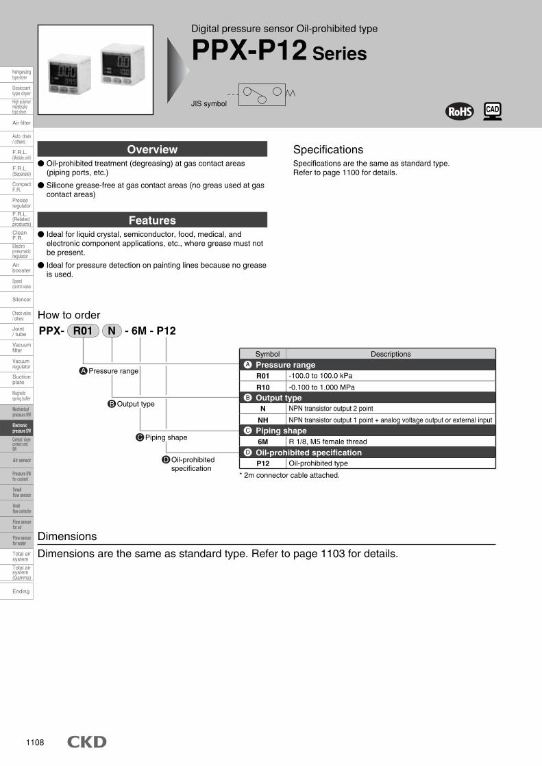
How to order
Symbol Descriptions
R01
R10
-100.0 to 100.0 kPa
-0.100 to 1.000 MPa
6M R 1/8, M5 female thread
P12 Oil-prohibited type
* 2m connector cable attached.
N
NH
NPN transistor output 2 point
NPN transistor output 1 point + analog voltage output or external input
PPX- R01 N - 6M - P12
Pressure rangeA
Output typeB
Piping shapeC
Oil-prohibitedspecification
D
Pressure range
Output type
Piping shape
Oil-prohibited specification
A
B
C
D
Overview Specifications
Features
Dimensions
Dimensions are the same as standard type. Refer to page 1103 for details.
� Oil-prohibited treatment (degreasing) at gas contact areas (piping ports, etc.)
� Silicone grease-free at gas contact areas (no greas used at gas contact areas)
Specifications are the same as standard type.Refer to page 1100 for details.
� Ideal for liquid crystal, semiconductor, food, medical, and electronic component applications, etc., where grease must not be present.
� Ideal for pressure detection on painting lines because no grease is used.
Ending
Speedcontrol valve
Check valve/ others
Magneticspring buffer
Refrigeratingtype dryer
Desiccanttype dryer
High polymermembranetype dryer
Auto. drain/ others
F.R.L.(Module unit)
F.R.L.(Separate)
F.R.L.(Relatedproducts)
CleanF.R.
Airbooster
Joint/ tube
Suctionplate
Total airsystem
Total airsystem(Gamma)
Air filter
CompactF.R.
Preciseregulator
Electropneumaticregulator
Silencer
Vacuumregulator
Vacuumfilter
Contact / closecontact conf.SW
Mechanicalpressure SW
Electronicpressure SW
Pressure SWfor coolant
Smallflow sensor
Smallflow controller
Flow sensorfor air
Flow sensorfor water
Air sensor
Digital pressure sensor Oil-prohibited type
PPX-P12 Series
JIS symbol
MEMO
1109
With
dig
ital d
ispl
ayP
ress
ure
sens
or
Speedcontrol valve
Check valve/ others
Magneticspring buffer
Mechanicalpressure SW
Electronicpressure SW
Pressure SWfor coolant
Smallflow sensor
Smallflow controller
Flow sensorfor air
Flow sensorfor water
Air sensor
Contact / closecontact conf.SW
Refrigeratingtype dryer
Desiccanttype dryer
High polymermembranetype dryer
Auto. drain/ others
F.R.L.(Module unit)
F.R.L.(Separate)
F.R.L.(Relatedproducts)
CleanF.R.
Airbooster
Joint/ tube
Suctionplate
Total airsystem
Total airsystem(Gamma)
Air filter
CompactF.R.
Preciseregulator
Electropneumaticregulator
Silencer
Vacuumregulator
Ending
Vacuumfilter
1110
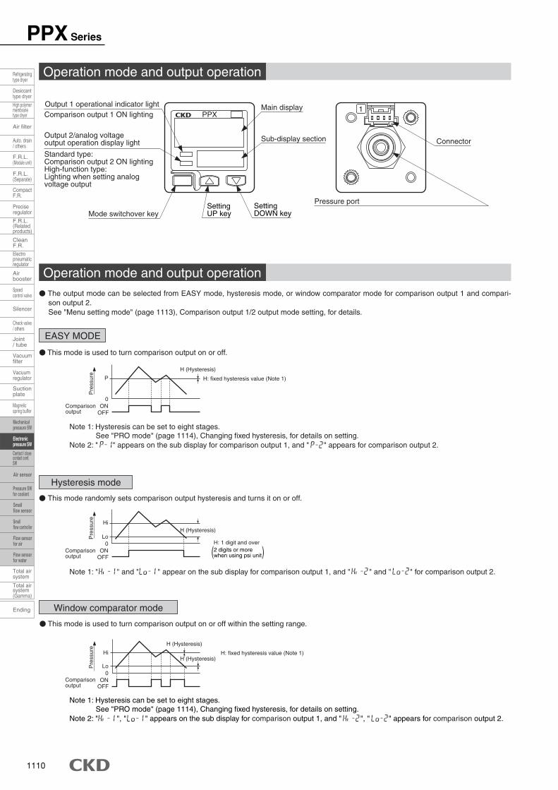
� The output mode can be selected from EASY mode, hysteresis mode, or window comparator mode for comparison output 1 and compari-son output 2. See "Menu setting mode" (page 1113), Comparison output 1/2 output mode setting, for details.
Note 1: Hysteresis can be set to eight stages. See "PRO mode" (page 1114), Changing fixed hysteresis, for details on setting.
Note 2: " " appears on the sub display for comparison output 1, and " " appears for comparison output 2.
� This mode randomly sets comparison output hysteresis and turns it on or off.
� This mode is used to turn comparison output on or off.
EASY MODE
Hysteresis mode
Window comparator mode
H (Hysteresis)
H: fixed hysteresis value (Note 1)P
0ON
OFFComparisonoutput
Comparisonoutput
Note 1: " " and " " appear on the sub display for comparison output 1, and " " and " " for comparison output 2.
Lo
Hi
0ON
OFF
Comparisonoutput
H (Hysteresis)
H: 1 digit and over
� This mode is used to turn comparison output on or off within the setting range.
Note 1: Hysteresis can be set to eight stages. See "PRO mode" (page 1114), Changing fixed hysteresis, for details on setting.
Note 2: " ", " " appears on the sub display for comparison output 1, and " ", " " appears for comparison output 2.
H (Hysteresis)
H: fixed hysteresis value (Note 1)H (Hysteresis)
Lo
Hi
0ON
OFF
Connector
Pressure port
1PPX
Mode switchover keySettingDOWN key
SettingUP key
Output 1 operational indicator lightComparison output 1 ON lighting
Output 2/analog voltageoutput operation display light
Standard type: Comparison output 2 ON lightingHigh-function type: Lighting when setting analogvoltage output
( )
Main display
Sub-display section
Operation mode and output operation
Operation mode and output operation
Pre
ssur
eP
ress
ure
Pre
ssur
e
2 digits or morewhen using psi unit
PPX Series
Ending
Speedcontrol valve
Check valve/ others
Magneticspring buffer
Refrigeratingtype dryer
Desiccanttype dryer
High polymermembranetype dryer
Auto. drain/ others
F.R.L.(Module unit)
F.R.L.(Separate)
F.R.L.(Relatedproducts)
CleanF.R.
Airbooster
Joint/ tube
Suctionplate
Total airsystem
Total airsystem(Gamma)
Air filter
CompactF.R.
Preciseregulator
Electropneumaticregulator
Silencer
Vacuumregulator
Vacuumfilter
Contact / closecontact conf.SW
Mechanicalpressure SW
Electronicpressure SW
Pressure SWfor coolant
Smallflow sensor
Smallflow controller
Flow sensorfor air
Flow sensorfor water
Air sensor
1111
With
dig
ital d
ispl
ayP
ress
ure
sens
or
Speedcontrol valve
Check valve/ others
Magneticspring buffer
Mechanicalpressure SW
Electronicpressure SW
Pressure SWfor coolant
Smallflow sensor
Smallflow controller
Flow sensorfor air
Flow sensorfor water
Air sensor
Contact / closecontact conf.SW
Refrigeratingtype dryer
Desiccanttype dryer
High polymermembranetype dryer
Auto. drain/ others
F.R.L.(Module unit)
F.R.L.(Separate)
F.R.L.(Relatedproducts)
CleanF.R.
Airbooster
Joint/ tube
Suctionplate
Total airsystem
Total airsystem(Gamma)
Air filter
CompactF.R.
Preciseregulator
Electropneumaticregulator
Silencer
Vacuumregulator
Ending
Vacuumfilter
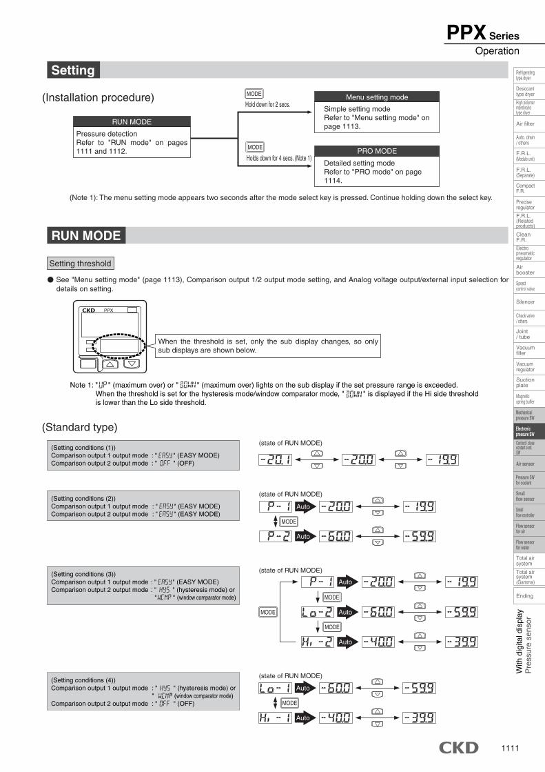
(Installation procedure)
RUN MODE
Pressure detection Refer to "RUN mode" on pages 1111 and 1112.
Menu setting mode
Simple setting mode Refer to "Menu setting mode" on page 1113.
PRO MODE
Detailed setting mode Refer to "PRO mode" on page 1114.
Hold down for 2 secs.
MODE
Holds down for 4 secs. (Note 1)
MODE
(Note 1): The menu setting mode appears two seconds after the mode select key is pressed. Continue holding down the select key.
(Setting conditions (4))Comparison output 1 output mode : " " (hysteresis mode) or
" " (window comparator mode)Comparison output 2 output mode : " " (OFF)
(Standard type)
(Setting conditions (1))Comparison output 1 output mode : " " (EASY MODE)Comparison output 2 output mode : " " (OFF)
(Setting conditions (2))Comparison output 1 output mode : " " (EASY MODE)Comparison output 2 output mode : " " (EASY MODE)
(Setting conditions (3))Comparison output 1 output mode : " " (EASY MODE)Comparison output 2 output mode : " " (hysteresis mode) or
" " (window comparator mode)
Note 1: " " (maximum over) or " " (maximum over) lights on the sub display if the set pressure range is exceeded. When the threshold is set for the hysteresis mode/window comparator mode, " " is displayed if the Hi side threshold is lower than the Lo side threshold.
� See "Menu setting mode" (page 1113), Comparison output 1/2 output mode setting, and Analog voltage output/external input selection for details on setting.
When the threshold is set, only the sub display changes, so only sub displays are shown below.
PPX
MODE
Auto
Auto
MODE
Auto
Auto
MODE
MODE
MODE
Auto
Auto
Auto
Setting threshold
Setting
RUN MODE
(state of RUN MODE)
(state of RUN MODE)
(state of RUN MODE)
(state of RUN MODE)
PPX SeriesOperation
1112
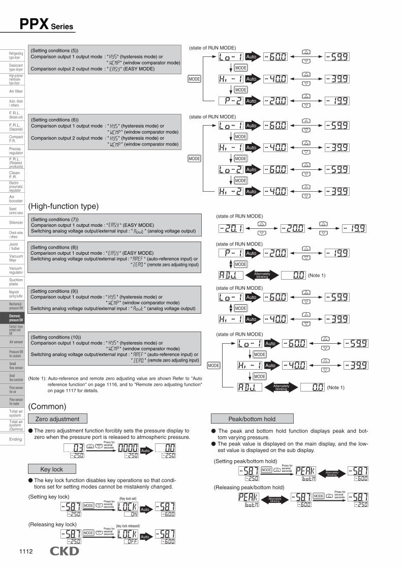
(Setting conditions (5))Comparison output 1 output mode : " " (hysteresis mode) or
" " (window comparator mode)Comparison output 2 output mode : " " (EASY MODE)
(Setting conditions (6))Comparison output 1 output mode : " " (hysteresis mode) or
" " (window comparator mode)Comparison output 2 output mode : " " (hysteresis mode) or
" " (window comparator mode)
(High-function type)
(Setting conditions (7))Comparison output 1 output mode : " " (EASY MODE)Switching analog voltage output/external input : " " (analog voltage output)
(state of RUN MODE)
(Setting conditions (9))Comparison output 1 output mode : " " (hysteresis mode) or
" " (window comparator mode)Switching analog voltage output/external input : " " (analog voltage output)
(state of RUN MODE)
MODE
Auto
Auto
(Setting conditions (8))Comparison output 1 output mode : " " (EASY MODE)Switching analog voltage output/external input : " " (auto-reference input) or
" " (remote zero adjusting input) MODE
(state of RUN MODE)
Auto
Alternatelyblinking (Note 1)
(Setting conditions (10))Comparison output 1 output mode : " " (hysteresis mode) or
" " (window comparator mode)Switching analog voltage output/external input : " " (auto-reference input) or
" " (remote zero adjusting input)
(state of RUN MODE)
MODE
MODE
MODE
Auto
Auto
Alternatelyblinking (Note 1)
(Note 1): Auto-reference and remote zero adjusting value are shown Refer to "Auto reference function" on page 1116, and to "Remote zero adjusting function" on page 1117 for details.
(Common)
� The zero adjustment function forcibly sets the pressure display to zero when the pressure port is released to atmospheric pressure.
Auto
Press forseveralseconds
Press forseveralseconds
Press forseveralseconds
Press forseveralseconds
Press forseveralseconds
� The key lock function disables key operations so that condi-tions set for setting modes cannot be mistakenly changed.
(Setting key lock)
(Releasing key lock)
Auto
(Key lock set)
MODE
(key lock released)
AutoMODE
� The peak and bottom hold function displays peak and bot-tom varying pressure.
� The peak value is displayed on the main display, and the low-est value is displayed on the sub display.
MODEAlternately
blinking
MODEAlternately
blinking
(Setting peak/bottom hold)
(Releasing peak/bottom hold)
(state of RUN MODE)
MODE
MODE
MODE
Auto
Auto
Auto
(state of RUN MODE)
MODE
MODE
MODE
MODE
Auto
Auto
Auto
Auto
Key lock
Zero adjustment Peak/bottom hold
PPX Series
Ending
Speedcontrol valve
Check valve/ others
Magneticspring buffer
Refrigeratingtype dryer
Desiccanttype dryer
High polymermembranetype dryer
Auto. drain/ others
F.R.L.(Module unit)
F.R.L.(Separate)
F.R.L.(Relatedproducts)
CleanF.R.
Airbooster
Joint/ tube
Suctionplate
Total airsystem
Total airsystem(Gamma)
Air filter
CompactF.R.
Preciseregulator
Electropneumaticregulator
Silencer
Vacuumregulator
Vacuumfilter
Contact / closecontact conf.SW
Mechanicalpressure SW
Electronicpressure SW
Pressure SWfor coolant
Smallflow sensor
Smallflow controller
Flow sensorfor air
Flow sensorfor water
Air sensor
1113
With
dig
ital d
ispl
ayP
ress
ure
sens
or
Speedcontrol valve
Check valve/ others
Magneticspring buffer
Mechanicalpressure SW
Electronicpressure SW
Pressure SWfor coolant
Smallflow sensor
Smallflow controller
Flow sensorfor air
Flow sensorfor water
Air sensor
Contact / closecontact conf.SW
Refrigeratingtype dryer
Desiccanttype dryer
High polymermembranetype dryer
Auto. drain/ others
F.R.L.(Module unit)
F.R.L.(Separate)
F.R.L.(Relatedproducts)
CleanF.R.
Airbooster
Joint/ tube
Suctionplate
Total airsystem
Total airsystem(Gamma)
Air filter
CompactF.R.
Preciseregulator
Electropneumaticregulator
Silencer
Vacuumregulator
Ending
Vacuumfilter
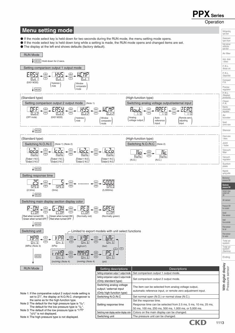
Note 1: If the comparative output 2 output mode setting is set to , the display at N.O./N.C. changeover is the same as for the high-function type.
Note 2: The default for the high pressure type is " ". The default for the low pressure type is " ".
Note 3: The default of the low pressure type is " "" " is not displayed.
Note 4: The high pressure type is not displayed.
( )
( ) ( )
Menu setting mode� If the mode select key is held down for two seconds during the RUN mode, the menu setting mode opens. � If the mode select key is held down long while a setting is made, the RUN mode opens and changed items are set. � The display at the left end shows defaults (factory default).
MODE
(2.5ms) (5ms) (5,000ms)
MODE
• • • • • • • •
MODE
(kPa) (bar)
(mmHg) (Note 4)(inchHg) (Note 4) (psi)
(kgf/cm2)(MPa) (Note 3)
(EASY MODE)
MODE
MODE
Hysteresismode
( )Hysteresismode
Windowcomparatormode
( )Windowcomparatormode
Analogvoltage output
Autoreferenceinput
Remote zeroadjustinginput
(Standard type) (High-function type)
(OFF mode)
(Note 1)
(EASY MODE)
(N.O.) (N.C.)
Hold down for 2 secs.MODE
MODE
Red when turned ONGreen when turned OFF
Green when turned ONRed when turned OFF
(Normally red) (Normally green)
Switching main display section display color
Switching unit
RUN Mode
Switching analog voltage output/external input
(High-function type)
Switching N.O./N.C
(Standard type)
(Note 1) (Note 2) (Note 2)
( ) ( )
( ) ( )
( ) ( )
Setting comparison output 1 output modeSetting comparison output 2 output mode(Only standard type)Switching analog voltageoutput / external input(Only high-function type)Switching N.O./N.C
Setting response time
Switching main display section display colorSwitching unit
Set comparison output 1 output mode.
Set comparison output 2 output mode.
The item can be selected from analog voltage output,automatic reference input, or remote zero adjustment input.
Set normal open (N.O.) or normal close (N.C.). Set the response time. Response time can be selected from 2.5 ms, 5 ms, 10 ms, 25 ms,50 ms, 100 ms, 250 ms, 500 ms, 1,000 ms, or 5,000 ms.Colors on the main display can be changed. The pressure unit can be changed.
Setting descriptions Descriptions
Limited to export models with unit select functions
RUN Mode
Setting comparison output 1 output mode
( )Output 1: N.O.Output 2: N.O.
Output 1: N.C.Output 2: N.C. ( )Output 1: N.C.
Output 2: N.O.Output 1: N.O.Output 2: N.C.
Setting response time
Switching N.O./N.C
Setting comparison output 2 output mode
PPX SeriesOperation
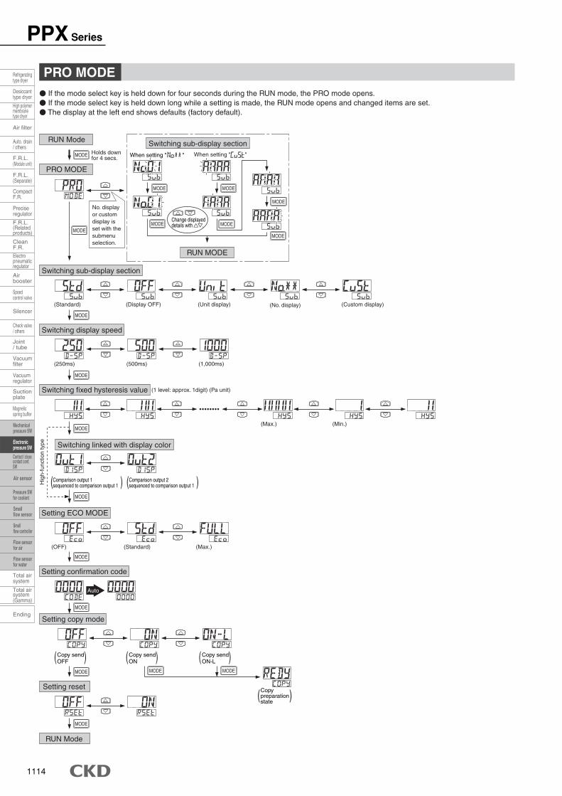
1114
( )( )
( ) ( ) ( )
When setting " "
� If the mode select key is held down for four seconds during the RUN mode, the PRO mode opens. � If the mode select key is held down long while a setting is made, the RUN mode opens and changed items are set. � The display at the left end shows defaults (factory default).
(Custom display)
Comparison output 1sequenced to comparison output 1
Comparison output 2sequenced to comparison output 1
(1 level: approx. 1digit) (Pa unit)
Holds downfor 4 secs. When setting " "
Change displayeddetails with ��.
MODE MODE
MODE
MODE
MODEMODEMODE
MODE
MODE
MODE
MODE
MODE
MODE
MODE MODE MODE
••••••••
Auto
(Standard) (Display OFF) (Unit display)
(250ms) (500ms) (1,000ms)
(OFF) (Standard) (Max.)
(No. display)
(Min.)(Max.)
MODE
Copy sendOFF
Copy sendON
Copy sendON-L
MODE
No. display or custom display is set with the submenu selection.
PRO MODE
RUN Mode
RUN MODE
Switching sub-display section
PRO MODE
Switching sub-display section
Switching display speed
Switching fixed hysteresis value
Switching linked with display color
Setting ECO MODE
Setting confirmation code
Setting copy mode
Setting reset
RUN Mode
Hig
h-fu
nctio
n ty
pe
Copypreparationstate
( )
PPX Series
Ending
Speedcontrol valve
Check valve/ others
Magneticspring buffer
Refrigeratingtype dryer
Desiccanttype dryer
High polymermembranetype dryer
Auto. drain/ others
F.R.L.(Module unit)
F.R.L.(Separate)
F.R.L.(Relatedproducts)
CleanF.R.
Airbooster
Joint/ tube
Suctionplate
Total airsystem
Total airsystem(Gamma)
Air filter
CompactF.R.
Preciseregulator
Electropneumaticregulator
Silencer
Vacuumregulator
Vacuumfilter
Contact / closecontact conf.SW
Mechanicalpressure SW
Electronicpressure SW
Pressure SWfor coolant
Smallflow sensor
Smallflow controller
Flow sensorfor air
Flow sensorfor water
Air sensor
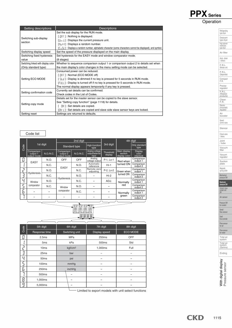
1115
With
dig
ital d
ispl
ayP
ress
ure
sens
or
Speedcontrol valve
Check valve/ others
Magneticspring buffer
Mechanicalpressure SW
Electronicpressure SW
Pressure SWfor coolant
Smallflow sensor
Smallflow controller
Flow sensorfor air
Flow sensorfor water
Air sensor
Contact / closecontact conf.SW
Refrigeratingtype dryer
Desiccanttype dryer
High polymermembranetype dryer
Auto. drain/ others
F.R.L.(Module unit)
F.R.L.(Separate)
F.R.L.(Relatedproducts)
CleanF.R.
Airbooster
Joint/ tube
Suctionplate
Total airsystem
Total airsystem(Gamma)
Air filter
CompactF.R.
Preciseregulator
Electropneumaticregulator
Silencer
Vacuumregulator
Ending
Vacuumfilter
Switching sub-displaysection
Switching display speedSwitching fixed hysteresisvalueSwitching linked with display color(Only standard type)
Setting ECO MODE
Setting confirmation code
Setting copy mode
Setting reset
Set the sub display for the RUN mode. [ ] : Nothing is displayed. [ ] : Displays the current pressure unit. [ ] : Displays a random number. [ ] : Displays a random number, alphabetic character (some characters cannot be displayed), and symbol.Set the speed of the pressure displayed on the main display. Set hysteresis for the EASY mode and window comparator mode. (8 stages)Whether to sequence comparison output 1 or comparison output 2 to details set whenthe main display's color changes in the menu setting mode can be selected. Consumed power can be reduced. [ ] : Normal (ECO MODE off) [ ] : Display is dimmed if no key is pressed for 5 seconds in RUN mode. [ ] : Display is turned off if no key is pressed for 5 seconds in RUN mode.The normal display appears temporarily if any key is pressed. Currently set details can be confirmed. Check codes in the List of Codes. Details set for the master sensor can be copied to the slave sensor. See "Setting copy function" (page 1118) for details. [ ] : Set details are copied. [ ] : Set details are copied and slave side slave sensor keys are locked.Settings are returned to defaults.
Setting descriptions Descriptions
- - - - --
- - --
--
ADJ.-
-
Analogvoltage output
Automatic reference
Remote zero adjusting
N.O. OFFOFF P-1, Lo-1
N.C. N.O. Hi-1
N.O. N.C. P-2, Lo-2
N.C. N.O. Hi-2
N.O. N.C.
N.C.
N.C. N.O.
EASY
Hysteresis
Windowcomparator
EASY
Hysteresis
Windowcomparator
1st digit2nd digit
Standard type3rd digit
4th digit
Cod
e
2.5ms MPa 250ms OFF
5ms kPa 500ms Std
10ms kgf/cm2 1,000ms Full
25ms bar - -
50ms psi - -
100ms mmHg - -
250ms inchHg - -
500ms - - -
1,000ms - - -
5,000ms - - -
Response time Switching unit Display speed ECO MODECod
e
Code list
Limited to export models with unit select functions
Comparisonoutput 1
output modeN.O./N.C. N.O./N.C.
Comparisonoutput 2
output mode
Displaycolor
interlock
Main displaysection
display color
Thresholddisplay
Analog voltageoutput/external
input
Only standardtype
High-functiontype
Comparisonoutput 1
Comparisonoutput 2
Comparisonoutput 1
Comparisonoutput 2
Comparisonoutput 1
Comparisonoutput 2
Comparisonoutput 1
Comparisonoutput 2
5th digit 6th digit 7th digit 8th digit
Red whenturned ON
Green whenturned ON
Normallyred
Normallygreen
��
( )
PPX SeriesOperation
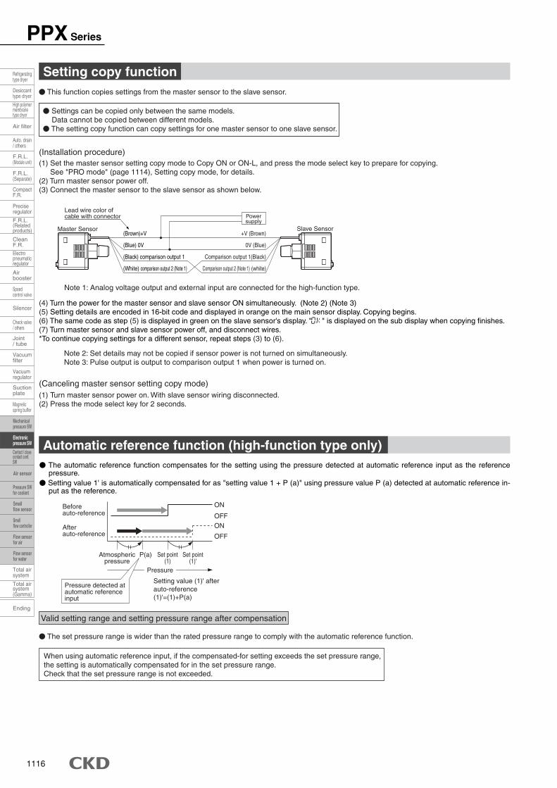
1116
Setting copy function
(1) Set the master sensor setting copy mode to Copy ON or ON-L, and press the mode select key to prepare for copying. See "PRO mode" (page 1114), Setting copy mode, for details.
(2) Turn master sensor power off. (3) Connect the master sensor to the slave sensor as shown below.
(Installation procedure)
(Canceling master sensor setting copy mode)(1) Turn master sensor power on. With slave sensor wiring disconnected. (2) Press the mode select key for 2 seconds.
(4) Turn the power for the master sensor and slave sensor ON simultaneously. (Note 2) (Note 3)(5) Setting details are encoded in 16-bit code and displayed in orange on the main sensor display. Copying begins. (6) The same code as step (5) is displayed in green on the slave sensor's display. " " is displayed on the sub display when copying finishes. (7) Turn master sensor and slave sensor power off, and disconnect wires. *To continue copying settings for a different sensor, repeat steps (3) to (6).
� Settings can be copied only between the same models. Data cannot be copied between different models.
� The setting copy function can copy settings for one master sensor to one slave sensor.
(Brown)+V +V (Brown)
(Blue) 0V 0V (Blue)
(Black) comparison output 1 Comparison output 1(Black)
(White) comparison output 2 (Note 1) Comparison output 2 (Note 1) (white)
Master Sensor Slave Sensor
Powersupply
Lead wire color ofcable with connector
� The automatic reference function compensates for the setting using the pressure detected at automatic reference input as the reference pressure.
� Setting value 1' is automatically compensated for as "setting value 1 + P (a)" using pressure value P (a) detected at automatic reference in-put as the reference.
When using automatic reference input, if the compensated-for setting exceeds the set pressure range, the setting is automatically compensated for in the set pressure range. Check that the set pressure range is not exceeded.
Set point(1)
Beforeauto-reference
Set point(1)'
Afterauto-reference
P(a)Atmosphericpressure
Pressure
ON
OFFON
OFF
Pressure detected atautomatic referenceinput
Setting value (1)' afterauto-reference(1)'=(1)+P(a)
� This function copies settings from the master sensor to the slave sensor.
Note 1: Analog voltage output and external input are connected for the high-function type.
Note 2: Set details may not be copied if sensor power is not turned on simultaneously. Note 3: Pulse output is output to comparison output 1 when power is turned on.
Valid setting range and setting pressure range after compensation
� The set pressure range is wider than the rated pressure range to comply with the automatic reference function.
Automatic reference function (high-function type only)
PPX Series
Ending
Speedcontrol valve
Check valve/ others
Magneticspring buffer
Refrigeratingtype dryer
Desiccanttype dryer
High polymermembranetype dryer
Auto. drain/ others
F.R.L.(Module unit)
F.R.L.(Separate)
F.R.L.(Relatedproducts)
CleanF.R.
Airbooster
Joint/ tube
Suctionplate
Total airsystem
Total airsystem(Gamma)
Air filter
CompactF.R.
Preciseregulator
Electropneumaticregulator
Silencer
Vacuumregulator
Vacuumfilter
Contact / closecontact conf.SW
Mechanicalpressure SW
Electronicpressure SW
Pressure SWfor coolant
Smallflow sensor
Smallflow controller
Flow sensorfor air
Flow sensorfor water
Air sensor
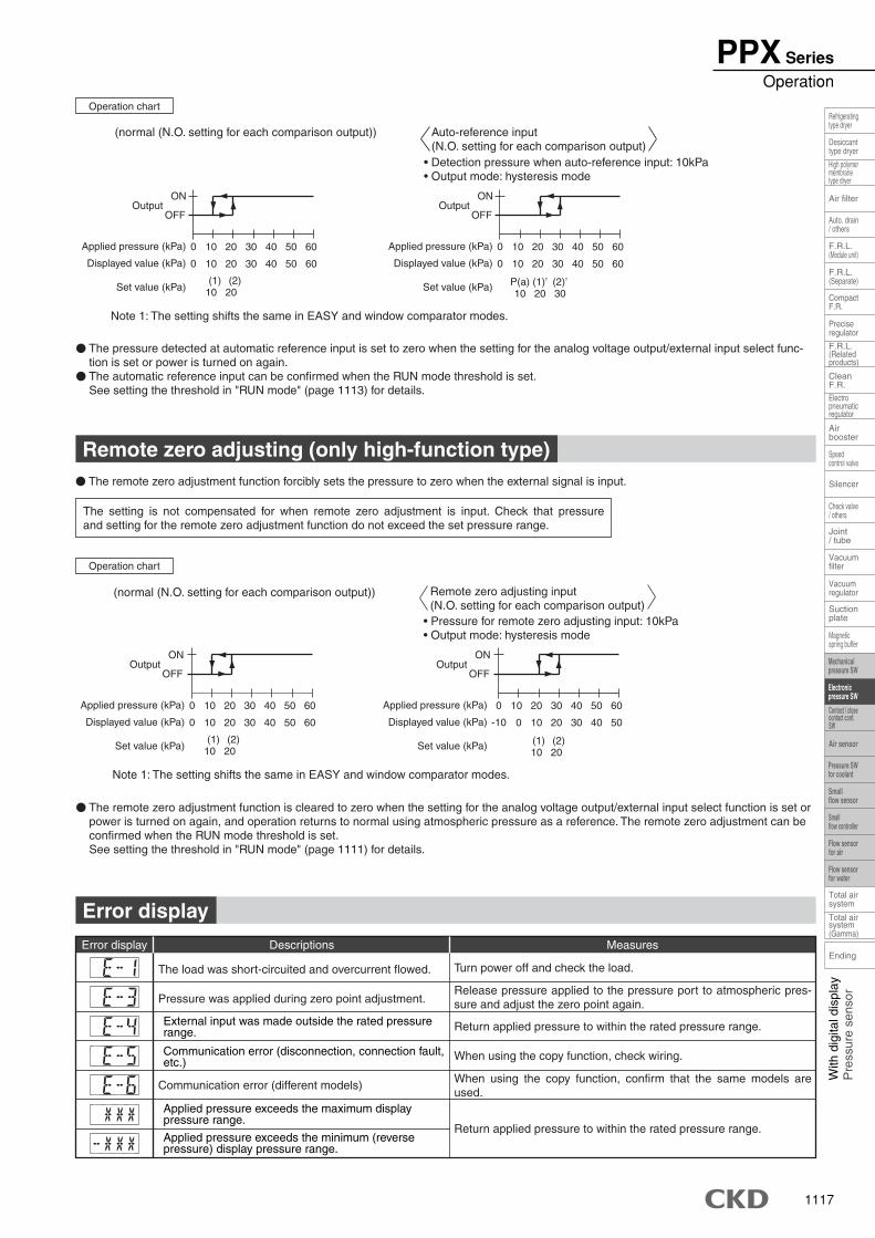
1117
With
dig
ital d
ispl
ayP
ress
ure
sens
or
Speedcontrol valve
Check valve/ others
Magneticspring buffer
Mechanicalpressure SW
Electronicpressure SW
Pressure SWfor coolant
Smallflow sensor
Smallflow controller
Flow sensorfor air
Flow sensorfor water
Air sensor
Contact / closecontact conf.SW
Refrigeratingtype dryer
Desiccanttype dryer
High polymermembranetype dryer
Auto. drain/ others
F.R.L.(Module unit)
F.R.L.(Separate)
F.R.L.(Relatedproducts)
CleanF.R.
Airbooster
Joint/ tube
Suctionplate
Total airsystem
Total airsystem(Gamma)
Air filter
CompactF.R.
Preciseregulator
Electropneumaticregulator
Silencer
Vacuumregulator
Ending
Vacuumfilter
The setting is not compensated for when remote zero adjustment is input. Check that pressure and setting for the remote zero adjustment function do not exceed the set pressure range.
� The remote zero adjustment function is cleared to zero when the setting for the analog voltage output/external input select function is set or power is turned on again, and operation returns to normal using atmospheric pressure as a reference. The remote zero adjustment can be confirmed when the RUN mode threshold is set. See setting the threshold in "RUN mode" (page 1111) for details.
(normal (N.O. setting for each comparison output))
ON
OFF
10 20 30 40 50 600
10 20 30 40 50 600
(2)(1)2010
Output
Applied pressure (kPa)
Displayed value (kPa)
Set value (kPa) (1) (2)10 20
ON
OFF
10 20 30 40 50 600
0 10 20 30 40 50-10
Output
Applied pressure (kPa)
Displayed value (kPa)
Set value (kPa)
• Pressure for remote zero adjusting input: 10kPa • Output mode: hysteresis mode
Remote zero adjusting input(N.O. setting for each comparison output)
Return applied pressure to within the rated pressure range.
When using the copy function, check wiring.
When using the copy function, confirm that the same models are used.
Communication error (different models)
Return applied pressure to within the rated pressure range.
Release pressure applied to the pressure port to atmospheric pres-sure and adjust the zero point again. Pressure was applied during zero point adjustment.
Turn power off and check the load.
Measures
The load was short-circuited and overcurrent flowed.
Error display Descriptions
(normal (N.O. setting for each comparison output))
• Detection pressure when auto-reference input: 10kPa • Output mode: hysteresis mode
� The pressure detected at automatic reference input is set to zero when the setting for the analog voltage output/external input select func-tion is set or power is turned on again.
� The automatic reference input can be confirmed when the RUN mode threshold is set. See setting the threshold in "RUN mode" (page 1113) for details.
ON
OFF
10 20 30 40 50 600
10 20 30 40 50 600
(1) (2)10 20
Output
Applied pressure (kPa)
Displayed value (kPa)
Set value (kPa) (1)’ (2)’20 30
P(a)10
ON
OFF
10 20 30 40 50 600
10 20 30 40 50 600
Output
Applied pressure (kPa)
Displayed value (kPa)
Set value (kPa)
Auto-reference input(N.O. setting for each comparison output)
Note 1: The setting shifts the same in EASY and window comparator modes.
Remote zero adjusting (only high-function type)
Error display
� The remote zero adjustment function forcibly sets the pressure to zero when the external signal is input.
Note 1: The setting shifts the same in EASY and window comparator modes.
Applied pressure exceeds the minimum (reversepressure) display pressure range.
Applied pressure exceeds the maximum displaypressure range.
External input was made outside the rated pressurerange.
Communication error (disconnection, connection fault,etc.)
Operation chart
Operation chart
PPX SeriesOperation
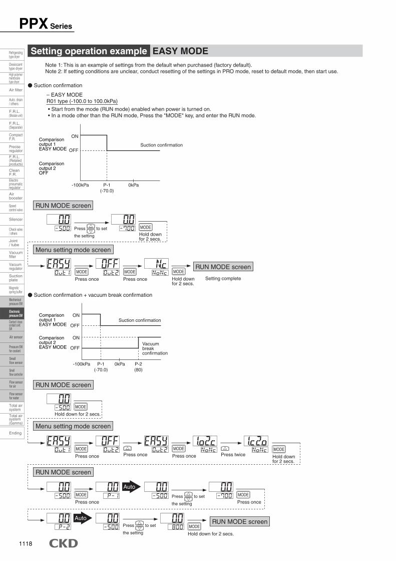
1118
Setting operation example EASY MODE
� Suction confirmation + vacuum break confirmation
Note 1: This is an example of settings from the default when purchased (factory default).Note 2: If setting conditions are unclear, conduct resetting of the settings in PRO mode, reset to default mode, then start use.
� Suction confirmation
– EASY MODE R01 type (-100.0 to 100.0kPa)
• Start from the mode (RUN mode) enabled when power is turned on. • In a mode other than the RUN mode, Press the "MODE" key, and enter the RUN mode.
OFF
ON
-100kPa P-1(-70.0)
0kPa
Suction confirmation
RUN MODE screen
Menu setting mode screen
Press to set
the setting
Hold downfor 2 secs.
MODE
Press once
MODE
Press once
MODE
RUN MODE screen
RUN MODE screen
Menu setting mode screen
Press once
MODE
Press once
MODEPress once Press twice
OFF
ON
OFF
ONComparisonoutput 2EASY MODE
-100kPa P-1(-70.0)
P-2(80)
0kPa
Suction confirmation
Vacuumbreakconfirmation
Auto
AutoRUN MODE screen
Hold downfor 2 secs.
MODE
Hold down for 2 secs.
MODE
Hold downfor 2 secs.
MODE
Hold down for 2 secs.
MODE
Press once
MODE
Press once
MODE
Setting complete
RUN MODE screen
Comparisonoutput 1EASY MODE
Comparisonoutput 2OFF
Comparisonoutput 1EASY MODE
Press to set
the setting
Press to set
the setting
PPX Series
Ending
Speedcontrol valve
Check valve/ others
Magneticspring buffer
Refrigeratingtype dryer
Desiccanttype dryer
High polymermembranetype dryer
Auto. drain/ others
F.R.L.(Module unit)
F.R.L.(Separate)
F.R.L.(Relatedproducts)
CleanF.R.
Airbooster
Joint/ tube
Suctionplate
Total airsystem
Total airsystem(Gamma)
Air filter
CompactF.R.
Preciseregulator
Electropneumaticregulator
Silencer
Vacuumregulator
Vacuumfilter
Contact / closecontact conf.SW
Mechanicalpressure SW
Electronicpressure SW
Pressure SWfor coolant
Smallflow sensor
Smallflow controller
Flow sensorfor air
Flow sensorfor water
Air sensor
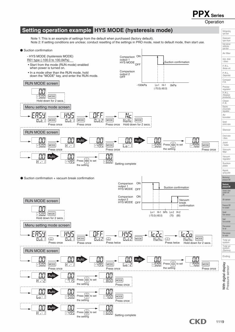
1119
With
dig
ital d
ispl
ayP
ress
ure
sens
or
Speedcontrol valve
Check valve/ others
Magneticspring buffer
Mechanicalpressure SW
Electronicpressure SW
Pressure SWfor coolant
Smallflow sensor
Smallflow controller
Flow sensorfor air
Flow sensorfor water
Air sensor
Contact / closecontact conf.SW
Refrigeratingtype dryer
Desiccanttype dryer
High polymermembranetype dryer
Auto. drain/ others
F.R.L.(Module unit)
F.R.L.(Separate)
F.R.L.(Relatedproducts)
CleanF.R.
Airbooster
Joint/ tube
Suctionplate
Total airsystem
Total airsystem(Gamma)
Air filter
CompactF.R.
Preciseregulator
Electropneumaticregulator
Silencer
Vacuumregulator
Ending
Vacuumfilter
Setting operation example HYS MODE (hysteresis mode)
� Suction confirmation + vacuum break confirmation
Note 1: This is an example of settings from the default when purchased (factory default).Note 2: If setting conditions are unclear, conduct resetting of the settings in PRO mode, reset to default mode, then start use.
� Suction confirmation
- HYS MODE (hysteresis MODE)R01 type (-100.0 to 100.0kPa)
• Start from the mode (RUN mode) enabledwhen power is turned on.
• In a mode other than the RUN mode, holddown the "MODE" key, and enter the RUN mode.
RUN MODE screen
Menu setting mode screen
RUN MODE screen
RUN MODE screen
RUN MODE screen
Menu setting mode screen
Press twicePress onceMODE
Press twice
Auto
Auto
Auto
Auto
OFF
ON
-100kPa Lo-1(-70.0)
Hi-1(-60.0)
Suction confirmation
0kPa
Comparisonoutput 1HYS MODE
Comparisonoutput 2OFF
Auto Auto
Auto
Setting complete
Auto
Setting complete
Lo-1(-70.0)
Hi-1(-60.0)
Lo-2(70)
Hi-2(80)
OFF
ON
OFF
ON
0kPa
Suction confirmation
Vacuumbreakconfirmation
Comparisonoutput 1HYS MODE
Comparisonoutput 2HYS MODE
Hold down for 2 secs.
MODE
Press once
MODE
Press once
MODE
Press once
MODE
Press once
MODE
Press once
MODE
Press once
MODE
Hold down for 2 secs.
MODE
Hold down for 2 secs.
MODE
Press once
MODE
Press once
MODE
Press once
MODE
Press once
MODE
Press once
MODE
Press once
MODE
Hold down for 2 secs.
MODE
Press to set
the setting
Press to set
the setting
Press to set
the setting
Press to set
the setting
Press to set
the setting
Press to set
the setting
PPX SeriesOperation
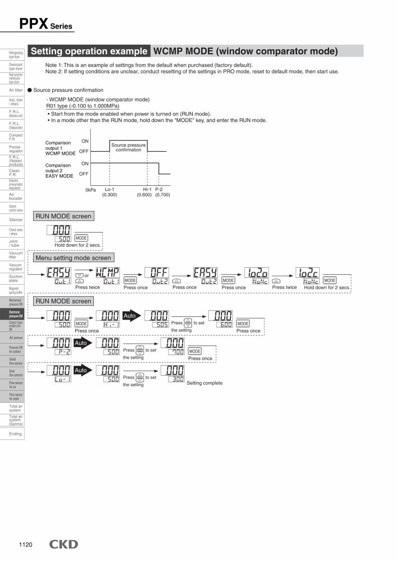
1120
Setting operation example WCMP MODE (window comparator mode)Note 1: This is an example of settings from the default when purchased (factory default).Note 2: If setting conditions are unclear, conduct resetting of the settings in PRO mode, reset to default mode, then start use.
� Source pressure confirmation
- WCMP MODE (window comparator mode)R01 type (-0.100 to 1.000MPa)
• Start from the mode enabled when power is turned on (RUN mode). • In a mode other than the RUN mode, hold down the "MODE" key, and enter the RUN mode.
RUN MODE screen
OFF
ON
OFF
ON
Comparisonoutput 1WCMP MODE
Comparisonoutput 2EASY MODE
Lo-1(0.300)
Hi-1(0.600)
P-2(0.700)
0kPa
Source pressureconfirmation
RUN MODE screen
Menu setting mode screen
Press oncePress twice Press twice
Auto
Auto
or
Auto
Setting complete
Hold down for 2 secs.
MODE
Press once
MODE
Press once
MODE
Press once
MODE
Press once
MODE
Hold down for 2 secs.
MODE
Press once
MODE
Press to set
the setting
Press to set
the setting
Press to set
the setting
PPX Series
Ending
Speedcontrol valve
Check valve/ others
Magneticspring buffer
Refrigeratingtype dryer
Desiccanttype dryer
High polymermembranetype dryer
Auto. drain/ others
F.R.L.(Module unit)
F.R.L.(Separate)
F.R.L.(Relatedproducts)
CleanF.R.
Airbooster
Joint/ tube
Suctionplate
Total airsystem
Total airsystem(Gamma)
Air filter
CompactF.R.
Preciseregulator
Electropneumaticregulator
Silencer
Vacuumregulator
Vacuumfilter
Contact / closecontact conf.SW
Mechanicalpressure SW
Electronicpressure SW
Pressure SWfor coolant
Smallflow sensor
Smallflow controller
Flow sensorfor air
Flow sensorfor water
Air sensor