Embed Size (px)
Citation preview

Electronic-Key-System Manual
Electronic-Key Adapter EKS and EKS FSA with Ethernet Interface
Order No. 100 420
Ethernet

Manual EKS Electronic-Key Adapter Ethernet
Table of contents
1 General notes...............................................................................................................................................4
1.1 Use of the manual..................................................................................................................................4 1.1.1 Explanation of symbols ..............................................................................................................4 1.1.2 Abbreviations .............................................................................................................................5
1.2 CE conformity.........................................................................................................................................5 1.3 Approvals ...............................................................................................................................................5 1.4 Correct use.............................................................................................................................................6 1.5 Obligations on the operating organization .............................................................................................7
2 Safety precautions.......................................................................................................................................8
3 Function........................................................................................................................................................9
3.1 Functional description ............................................................................................................................9 3.1.1 Common functions of EKS standard and version EKS FSA......................................................9 3.1.2 Additional functions of the version EKS FSA .......................................................................... 10
4 Technical data........................................................................................................................................... 11
4.1 Dimension drawing of Electronic-Key adapter.................................................................................... 11 4.1.1 Version EKS-A-IEX-G01-ST02/03 with Ethernet interface ..................................................... 11 4.1.2 Version EKS-A-IEXA-G01-ST02/03/04 (EKS FSA) with Ethernet interface ........................... 11
4.2 Technical data of Electronic-Key adapter ........................................................................................... 12 4.3 Connector configuration...................................................................................................................... 13
4.3.1 Connection socket for Ethernet interface................................................................................ 13 4.3.2 Plug-in screw terminals for power supply ............................................................................... 13 4.3.3 Plug-in screw terminals for outputs LA1/LA2 and LB1/LB2 (EKS FSA only).......................... 13
4.4 DIP switch settings.............................................................................................................................. 14 4.4.1 DIP switch S1.......................................................................................................................... 14 4.4.2 DIP switch S2.......................................................................................................................... 14 4.4.3 DIP switch S3.......................................................................................................................... 15
4.5 LED indicator....................................................................................................................................... 15
5 Mounting.................................................................................................................................................... 16
6 Electrical connection................................................................................................................................ 17
6.1 Ethernet connection ............................................................................................................................ 17 6.1.1 Ethernet configuration ............................................................................................................. 18
6.2 Connection of power supply................................................................................................................ 20 6.3 Connection of function earth ............................................................................................................... 20
Page 2/40 Subject to technical modifications 100420-02-01/09

Manual EKS Electronic-Key Adapter Ethernet
6.4 Connection of the switched outputs (for EKS FSA only) .....................................................................20 6.4.1 Connection example with enabling switch ...............................................................................21 6.4.2 Connection example without enabling switch ..........................................................................24
7 Setup...........................................................................................................................................................27
7.1 Network settings ..................................................................................................................................27 7.1.1 Network settings for a configuration PC with Windows® XP....................................................27
7.2 Configuring the Electronic-Key adapter via the web interface.............................................................30 7.3 Reading key data using the web interface...........................................................................................32
8 Data transfer via the Ethernet interface ..................................................................................................33
8.1 Communication ....................................................................................................................................33 8.2 Basic message structure .....................................................................................................................33
8.2.1 IP – Internet Protocol ...............................................................................................................33 8.2.2 TCP – Transport Control Protocol............................................................................................33
8.3 Commands for writing and reading a read/write Electronic-Key .........................................................34 8.3.1 Write process ...........................................................................................................................35 8.3.2 Read process ...........................................................................................................................36 8.3.3 Reading the serial number.......................................................................................................37 8.3.4 Reading the key status ............................................................................................................37
8.4 Command overview .............................................................................................................................38 8.5 Status numbers....................................................................................................................................38
9 Exclusion of liability..................................................................................................................................39
10 Service and repair .....................................................................................................................................39
11 Guarantee...................................................................................................................................................39
100420-02-01/09 Subject to technical modifications Page 3/40

Manual EKS Electronic-Key Adapter Ethernet
1 General notes
1.1 Use of the manual This manual describes the technical features and the function of the EKS Electronic-Key adapter EKS-A-IEX-G01-ST02/03 with Ethernet interface (order no. 100 401) as well as the version EKS-A-IEXA-G01-ST02/03/04, EKS For Safety Applications (EKS FSA, order no. 099 265). The complete evaluation and interface electronics for data transmission is integrated in these units.
1.1.1 Explanation of symbols The following symbols are used in this manual to identify important instructions and useful information:
Danger! Identifies an immediate hazard. If not avoided, the consequence will be fatality or very serious injuries. Warning! Identifies a possible hazard. If not avoided, the consequence may be fatality or very serious injuries. Caution! Identifies a possible hazard. If not avoided, minor injuries or damage may result.
Attention! Risk of damage to material or machine or degradation of function.
Information! Important information is provided to the user here.
Page 4/40 Subject to technical modifications 100420-02-01/09

Manual EKS Electronic-Key Adapter Ethernet
1.1.2 Abbreviations The following abbreviations are used in this manual:
DHCP Dynamic Host Configuration Protocol
DIP Dual Inline Package
DNS Domain Name Service
E²PROM Electrically Erasable Programmable Read-Only Memory
EKS Electronic-Key-System
EKS FSA Electronic-Key-System For Safety Applications
IP Internet Protocol
LED Light Emitting Diode
LSB Least Significant Bit
MSB Most Significant Bit
PA PolyAmide
RD Receive Data
ROM Read-Only Memory
TCP Transmission Control Protocol
TD Transmit Data
1.2 CE conformity The EKS Electronic-Key adapters with Ethernet interface conform to the EMC directive 2007/108/EC (89/336/EEC, 92/31/EEC, 93/68/EEC) and the low voltage directive 2006/95/EC (73/23/EEC, 93/68/EEC, 98/79/EC).
The Electronic-Key adapters comply with the following European / international standards:
EN 61000-6-2 Electromagnetic compatibility (EMC). Generic standards - Immunity for industrial environments
EN 55011 Industrial, scientific and medical (ISM) radio-frequency equipment - Radio disturbance characteristics - Limits and methods of measurement
1.3 Approvals The EKS Electronic-Key adapters with Ethernet interface are certified to (UL file number E240367).
For use and operation as per the requirements, a power supply for use in class 2 circuits must be used.
100420-02-01/09 Subject to technical modifications Page 5/40

Manual EKS Electronic-Key Adapter Ethernet
1.4 Correct use As part of a higher-level overall system, the EKS Electronic-Key adapter is used for access control and monitoring on controllers or parts of controllers for machine installations. EKS can be used, for example, as part of an overall system for checking access rights for operating mode selection. However, it is not permitted to directly derive the operating mode from the access rights on the Electronic-Key. If the selection of the operating mode is relevant for safety, this must not be performed by means of the EKS; instead an additional device must be used to select the operating mode. This is possible via the graphical user interface on the control system, for example. The version EKS FSA has outputs that can be utilized to form a safe shut-down signal (for block diagram see section 3.1.2). For this purpose a safe evaluation must be included downstream. The EKS FSA can then be used for safety-related tasks. The machine must be reset to a safe operating mode by removing the Electronic-Key. A hazard analysis on this aspect must be prepared as per the requirements in the machinery directive. The risk and the necessary risk minimization by technical means must be determined using a suitable standard. The following requirements must be met for usage:
The data signal (channel LB) and the switched output LA1/LA2 (channel LA) must be polled by a safe downstream evaluation to suit the risk determined. The data wire (channel LB) is used to supply the information as to whether or not an Electronic-Key is inserted and which access rights are assigned to the Electronic-Key. The output LA1/LA2 (channel LA) is used for the redundant supply of the information as to whether or not an Electronic-Key is inserted (independent of the access rights). The data wire or, alternatively, the switched output LB1/LB2 can be used as channel LB. The output LB1/LB2 is used to supply (like LA1/LA2) only the information as to whether or not an Electronic-Key is inserted (independent of the access rights). The usage of the output LB1/LB2 is optional.
The control system must check whether the Electronic-Key inserted is authorized to select the operating mode and whether the access rights on the Electronic-Key permit operation in the operating mode currently selected.
The user must select the related operating mode using the control system or another suitable circuit.
The manufacturer of the system must check which safety level is reached with the overall system and whether the overall system provides adequate safety against hazards in the intended application.
Information! The machinery directive 98/37/EC provides information on selection of the operating mode. It is imperative this information is followed.
When designing machines and using the Electronic-Key adapter , the national and international regulations and standards specific to the application must be observed, e.g.:
EN 60204, Safety of machinery. Electrical equipment of machines
EN 12100-1, Safety of machinery. Basic concepts, general principles for design - part 1: basic terminology, methodology
EN 954-1, Safety of machinery. Safety related parts of control systems - part 1: general principles for design
EN 62061, Safety of machinery. Functional safety of safety-related electrical, electronic and programmable electronic control systems
EN ISO 13849-1, Safety of machinery. Safety related parts of control systems - part 1: general principles for design
Modifications to the electronics of the Electronic-Key adapter and any other changes, especially mechanical modifications and reworking, are not permissible and will result in the loss of the warranty and exclusion of liability.
Page 6/40 Subject to technical modifications 100420-02-01/09

Manual EKS Electronic-Key Adapter Ethernet
The Electronic-Key adapter must only be employed and used in accordance
with this manual and
other documentation referred to in this manual.
The EKS Electronic-Key adapter is not a safety component in the sense of the machinery directive.
Without additional precautions the EKS Electronic-Key adapter must not be used to provide a safety function, particularly if failure or malfunction of the unit could endanger the safety or health of people in the operating area of a machine.
1.5 Obligations on the operating organization The manufacturer and the organization operating the higher-level overall system, e.g. a machine installation, are responsible for the observance of national and international safety and accident prevention regulations applicable in the specific case.
100420-02-01/09 Subject to technical modifications Page 7/40

Manual EKS Electronic-Key Adapter Ethernet
2 Safety precautions
The EKS Electronic-Key adapter is not a safety component in the sense of the machinery directive. Without additional precautions the EKS Electronic-Key adapter must not be used to provide a safety function, particularly if failure or malfunction of the unit could endanger the safety or health of persons in the operating area of a machine. On this topic pay particular attention to the sections
Warning!
Correct use (see section 1.4) and Electrical connection (see section 6).
Mounting and electrical connection are only allowed to be performed by authorized personnel who are familiar with the applicable regulations on accident prevention and have read and understood this manual.
Warning!
Furthermore, the mounting and electrical connection of the version EKS FSA are only allowed to be performed by personnel familiar with handling safety components.
Modifications to the electronics of the Electronic-Key adapter and any other changes, especially mechanical modifications and reworking, are not permissible and will result in the loss of the warranty.
Caution!
Page 8/40 Subject to technical modifications 100420-02-01/09

Manual EKS Electronic-Key Adapter Ethernet
3 Function
3.1 Functional description
3.1.1 Common functions of EKS standard and version EKS FSA The EKS is used for access control and monitoring on controllers or parts of controllers for machine installations.
Instead of passwords, coded Electronic-Keys are assigned. In this way unauthorized access to control and display systems is prevented to the greatest possible extent.
The EKS uses a non-contact, inductive read/write identification system.
It comprises:
Electronic-Key
Electronic-Key adapter
The user is responsible for organizing the programming of the application, integration in an overall system and the assignment and use of the freely programmable memory in the Electronic-Key.
Information! For easier organization and management of your Electronic-Keys and the data they contain, EUCHNER also offers the Electronic-Key-Manager (EKM) software. To enter data in the EKM software, an Electronic-Key adapter with serial interface or USB interface must be in operation on the PC.
The Electronic-Key adapter is a read/write system with integrated evaluation electronics and interface.
Due to the transfer of data without using any contacts, from the access side the Electronic-Key adapter has the high degree of protection of IP 67, i.e. it is suitable for industrial use. The Electronic-Key adapter can be installed in accordance with DIN 43700 in any control panel with a standard cut-out of 33 mm x 68 mm. The Electronic-Key adapter is fastened by means of screw clamp elements from the rear side of the panel in order to exclude unauthorized manipulation from the operator side.
The system is connected using the integrated Ethernet interface that is designed as an RJ45 socket.
Setup and system integration can be realized straightforwardly and quickly on the Electronic-Key adapter with Ethernet interface. Data communication takes place via TCP/IP.
The current state of the Electronic-Key adapter is displayed using a 3-color LED.
The Electronic-Keys are tag shaped. The complete transponder with memory chip and antenna is integrated into the Electronic-Key. The transponder does not have a battery.
100420-02-01/09 Subject to technical modifications Page 9/40
Manual EKS Electronic-Key Adapter Ethernet
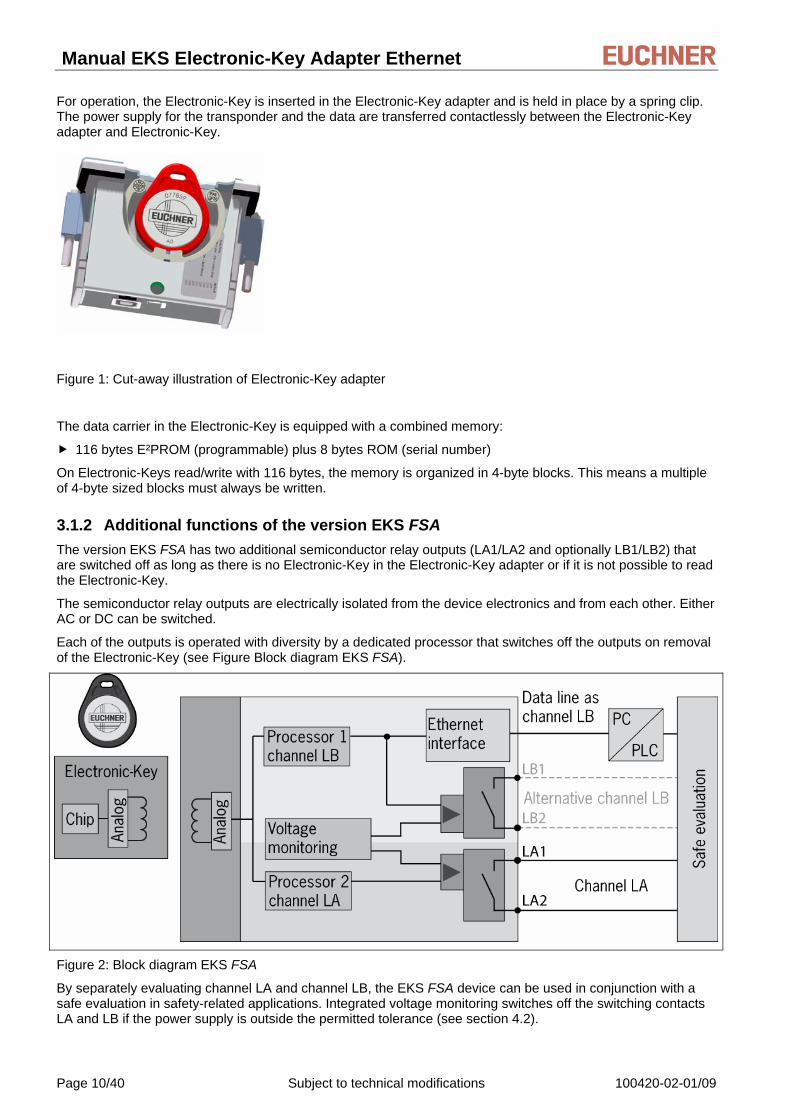
For operation, the Electronic-Key is inserted in the Electronic-Key adapter and is held in place by a spring clip. The power supply for the transponder and the data are transferred contactlessly between the Electronic-Key adapter and Electronic-Key.
Figure 1: Cut-away illustration of Electronic-Key adapter
The data carrier in the Electronic-Key is equipped with a combined memory:
116 bytes E²PROM (programmable) plus 8 bytes ROM (serial number)
On Electronic-Keys read/write with 116 bytes, the memory is organized in 4-byte blocks. This means a multiple of 4-byte sized blocks must always be written.
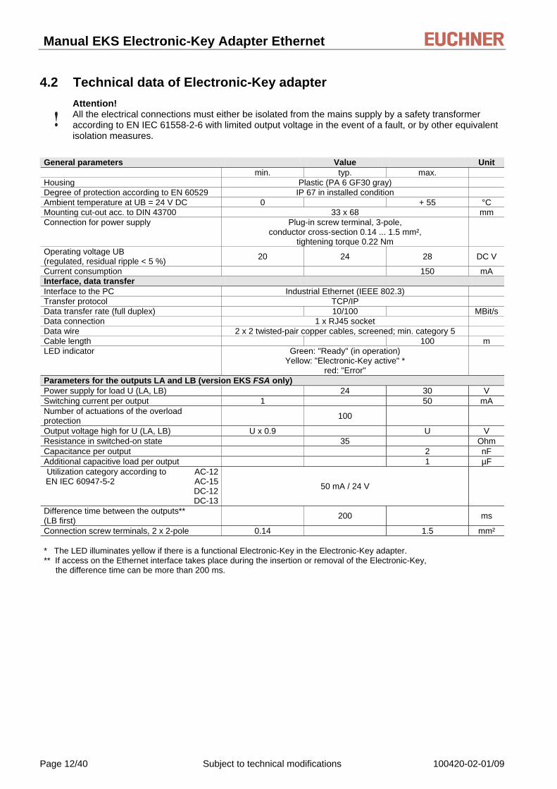
3.1.2 Additional functions of the version EKS FSA The version EKS FSA has two additional semiconductor relay outputs (LA1/LA2 and optionally LB1/LB2) that are switched off as long as there is no Electronic-Key in the Electronic-Key adapter or if it is not possible to read the Electronic-Key.
The semiconductor relay outputs are electrically isolated from the device electronics and from each other. Either AC or DC can be switched.
Each of the outputs is operated with diversity by a dedicated processor that switches off the outputs on removal of the Electronic-Key (see Figure Block diagram EKS FSA).
Figure 2: Block diagram EKS FSA
By separately evaluating channel LA and channel LB, the EKS FSA device can be used in conjunction with a safe evaluation in safety-related applications. Integrated voltage monitoring switches off the switching contacts LA and LB if the power supply is outside the permitted tolerance (see section 4.2).
Page 10/40 Subject to technical modifications 100420-02-01/09

Manual EKS Electronic-Key Adapter Ethernet
4 Technical data
4.1 Dimension drawing of Electronic-Key adapter For installation in a control panel you must provide a cut-out 33 mm x 68 mm according to DIN 43700.
4.1.1 Version EKS-A-IEX-G01-ST02/03 with Ethernet interface
4.1.2 Version EKS-A-IEXA-G01-ST02/03/04 (EKS FSA) with Ethernet interface
100420-02-01/09 Subject to technical modifications Page 11/40
Manual EKS Electronic-Key Adapter Ethernet
4.2 Technical data of Electronic-Key adapter
Attention! All the electrical connections must either be isolated from the mains supply by a safety transformer according to EN IEC 61558-2-6 with limited output voltage in the event of a fault, or by other equivalent isolation measures.
General parameters Value Unit min. typ. max. Housing Plastic (PA 6 GF30 gray) Degree of protection according to EN 60529 IP 67 in installed condition Ambient temperature at UB = 24 V DC 0 + 55 °C Mounting cut-out acc. to DIN 43700 33 x 68 mm Connection for power supply Plug-in screw terminal, 3-pole,
conductor cross-section 0.14 ... 1.5 mm², tightening torque 0.22 Nm
Operating voltage UB (regulated, residual ripple < 5 %) 20 24 28 DC V
Current consumption 150 mA Interface, data transfer Interface to the PC Industrial Ethernet (IEEE 802.3) Transfer protocol TCP/IP Data transfer rate (full duplex) 10/100 MBit/s Data connection 1 x RJ45 socket Data wire 2 x 2 twisted-pair copper cables, screened; min. category 5 Cable length 100 m LED indicator Green: "Ready" (in operation)
Yellow: "Electronic-Key active" * red: "Error"
Parameters for the outputs LA and LB (version EKS FSA only) Power supply for load U (LA, LB) 24 30 V Switching current per output 1 50 mA Number of actuations of the overload protection 100
Output voltage high for U (LA, LB) U x 0.9 U V Resistance in switched-on state 35 Ohm Capacitance per output 2 nF Additional capacitive load per output 1 µF Utilization category according to AC-12 EN IEC 60947-5-2 AC-15
DC-12 DC-13
50 mA / 24 V
Difference time between the outputs** (LB first) 200 ms
Connection screw terminals, 2 x 2-pole 0.14 1.5 mm² * The LED illuminates yellow if there is a functional Electronic-Key in the Electronic-Key adapter. ** If access on the Ethernet interface takes place during the insertion or removal of the Electronic-Key, the difference time can be more than 200 ms.
Page 12/40 Subject to technical modifications 100420-02-01/09

Manual EKS Electronic-Key Adapter Ethernet
4.3 Connector configuration
4.3.1 Connection socket for Ethernet interface The connection on the Electronic-Key adapter is realized as an RJ45 (8P8C) socket corresponding to ISO IEC 61754-24.
Pin Function 1 Transmit Data + (TD+) 2 Transmit Data - (TD-) 3 Receive Data + (RD+) 6 Receive Data - (RD-)
4.3.2 Plug-in screw terminals for power supply
Information! The coded plug for connection of the power supply is included with the Electronic-Key adapter .
Pin Designation Function
1 UB Power supply DC + 24 V
2 0V Power supply DC 0 V
1 2 3
Coded plug, 3-pin with screw terminals
Conductor cross-section 0.14 ... 1.5 mm²
Tightening torque 0.22 Nm 3 Function earth Electrically connected to the housing
4.3.3 Plug-in screw terminals for outputs LA1/LA2 and LB1/LB2 (EKS FSA only)
Information! The coded plug for the connection of the outputs is included with the Electronic-Key adapter .
Channel Pin Function
1 LA
2
Normally open contact channel LA
1
Coded plug 2 x 2-pin with screw terminals
Conductor cross-section 0.14 … 1.5 mm²
Tightening torque 0.22 Nm
LB Normally open contact channel LB
2
100420-02-01/09 Subject to technical modifications Page 13/40

Manual EKS Electronic-Key Adapter Ethernet
4.4 DIP switch settings The device has three DIP switches (S1, S2, S3).
DIP switch Function
S1 (4-fold) S1.1 … S1.4; write and read settings
S2 (8-fold) S2.1 … S2.8; setting of a fixed DNS name (required only for special applications)
S3 (4-fold) S3.1 …S3.4; settings for network connection and service
Information! The settings are only applied when the power supply is switched on.
4.4.1 DIP switch S1
DIP
switch Function Factory setting
S1.1 ON = write protection for read/write Electronic-Key OFF S1.2 No function OFF S1.3 No function OFF S1.4 No function OFF
Information! It is imperative that all DIP switches without a function (S1.2, S1.3 and S1.4) are set to OFF! In this way problems with any functions added in the future will be avoided.
4.4.2 DIP switch S2
DNS name
LSB S2.1
S2.2
S2.3
S2.4
S2.5
S2.6
S2.7
MSB S2.8
EKS000 OFF OFF OFF OFF OFF OFF OFF OFF EKS001 ON OFF OFF OFF OFF OFF OFF OFF EKS002 OFF ON OFF OFF OFF OFF OFF OFF EKS003 ON ON OFF OFF OFF OFF OFF OFF
… … … … … … … … … EKS254 OFF ON ON ON ON ON ON ON EKS255 ON ON ON ON ON ON ON ON
Information! All DIP switches S2 are relevant only in conjunction with the Siemens SINUMERIK DHCP address assignment (see section 6.1.1.3 Operation in the Siemens system network).
Page 14/40 Subject to technical modifications 100420-02-01/09
Manual EKS Electronic-Key Adapter Ethernet
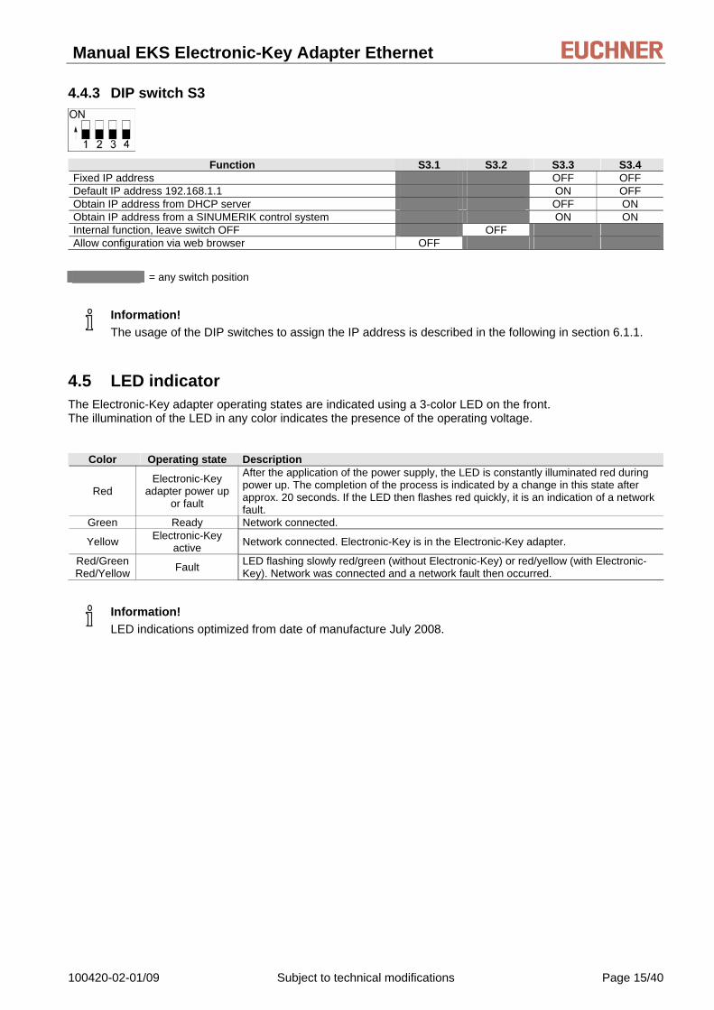
4.4.3 DIP switch S3
Function S3.1 S3.2 S3.3 S3.4
Fixed IP address OFF OFF Default IP address 192.168.1.1 ON OFF Obtain IP address from DHCP server OFF ON Obtain IP address from a SINUMERIK control system ON ON Internal function, leave switch OFF OFF Allow configuration via web browser OFF
= any switch position
Information! The usage of the DIP switches to assign the IP address is described in the following in section 6.1.1.
4.5 LED indicator The Electronic-Key adapter operating states are indicated using a 3-color LED on the front. The illumination of the LED in any color indicates the presence of the operating voltage.
Color Operating state Description
Red Electronic-Key
adapter power up or fault
After the application of the power supply, the LED is constantly illuminated red during power up. The completion of the process is indicated by a change in this state after approx. 20 seconds. If the LED then flashes red quickly, it is an indication of a network fault.
Green Ready Network connected.
Yellow Electronic-Key active Network connected. Electronic-Key is in the Electronic-Key adapter.
Red/Green Red/Yellow Fault LED flashing slowly red/green (without Electronic-Key) or red/yellow (with Electronic-
Key). Network was connected and a network fault then occurred.
Information! LED indications optimized from date of manufacture July 2008.
100420-02-01/09 Subject to technical modifications Page 15/40

Manual EKS Electronic-Key Adapter Ethernet
5 Mounting
Mounting must be performed only by authorized personnel. Warning!
Warning! To achieve the degree of protection IP 67, it is necessary to install the Electronic-Key adapter in a clean, flat metal plate at least 2 mm thick and to tighten the screws with a tightening torque of 0.25 ... 0.35 Nm. A suitable strain relief must be provided for the connection cables in order to avoid damage to the connection sockets or malfunctions.
The Electronic-Key adapter is intended for mounting in control panels with a cut-out measuring 33 mm x 68 mm according to DIN 43700 (see section 4.1). The device is fastened using screw clamp elements from the rear side of the plate.
Information! The screw clamp elements for front panel mounting are included with the Electronic-Key adapter .
1. Insert Electronic-Key adapter , with seal already bonded in place, into the mounting cut-out from the front.
2. Insert screw clamp elements in the housing of the Electronic-Key adapter from the side up to the stop and tighten with 0.25 …0.35 Nm.
Attention! The device may be damaged if the tightening torque applied exceeds 0.35 Nm.
3. After mounting, again check the Electronic-Key adapter for firm seating and correct sealing of the front panel.
Page 16/40 Subject to technical modifications 100420-02-01/09

Manual EKS Electronic-Key Adapter Ethernet
6 Electrical connection
Electrical connection may only be performed by authorized personnel trained in EMC and with the device and wiring isolated.
Danger!
For use and operation as per the Warning!
requirements, a power supply for use in class 2 circuits must be used.
Attention! The Electronic-Key adapter is only allowed to be connected if it is electrically isolated. Otherwise the Electronic-Key adapter may be damaged.
Attention! If connected incorrectly, the Electronic-Key adapter may be damaged. Observe electrical characteristics and the pin assignment (see section 4.2 Technical data of Electronic-Key adapter).
Attention! All the electrical connections must either be isolated from the mains supply by a safety transformer according to IEC/EN 61558-2-6 with limited output voltage in the event of a fault, or by other equivalent isolation measures.
Attention! When installing connections, the operating organization must ensure compliance with the EMC safety requirements in accordance with EN 55011 and EN 61000-6-2.
Attention! The equipotential bonding system of the machine installation must comply with EN 60204-1, section 8, Equipotential bonding.
Attention! Do not lay connection cables in the immediate vicinity of sources of interference.
6.1 Ethernet connection The interface for the Electronic-Key adapter is compatible with the standards ISO/IEC 61754-24 and IEC 61158. The Electronic-Key adapter is operated in full-duplex mode with 10 MBit/s or 100 MBit/s.
Information!
Only a screened 100 BaseTX cable, twisted pair, Cat5 or higher, is permitted for use as the connection cable. The maximum cable length is 100 m.
It may be necessary to provide additional screening in conditions with a high level of EMC interference.
100420-02-01/09 Subject to technical modifications Page 17/40

Manual EKS Electronic-Key Adapter Ethernet
6.1.1 Ethernet configuration The Electronic-Key adapter can be configured for the following operating modes with DIP switch S3 (see section 4.4.3):
With a fixed IP address
As a DHCP client with dynamic IP address
As a DHCP client for a SINUMERIK control system with dynamic IP address based on a fixed station name (see section 4.4.2)
In addition, the following service functions can be set with DIP switch S3:
Reset to default IP address (see sections 4.4.3 and 6.1.1.1)
Permit or prohibit configuration via a web browser (see sections 4.4.3 and 7.2)
The individual functions are described below in detail.
6.1.1.1 Fixed IP address and default IP address Fixed IP address
In this operating mode, communication with the Electronic-Key adapter is via a fixed IP address. In the default setting on delivery, the factory-set default IP address is 192.168.1.1 and the subnet mask is 255.255.255.0.
Information! This operating mode is not suitable for operation in conjunction with a DHCP server.
The DIP switches S3.3 and S3.4 always remain OFF in this operating mode (see DIP switch settings in section 4.4.3).
On powering up the Electronic-Key adapter, the fixed IP address last set is always active after the application of the power supply in this operating mode.
You can assign an individual fixed IP address via the web interface of the Electronic-Key adapter (see section 7.2). To do this, access via a web browser must be enabled (see DIP switch settings in section 4.4.3). Default IP address
Every Electronic-Key adapter has the factory-set default IP address 192.168.1.1 and the subnet mask 255.255.255.0.
Information! If you have forgotten your self-defined IP address, you can reset the Electronic-Key adapter to the default address again. The self-defined address is then overwritten by the default address.
For this purpose proceed as follows. The Electronic-Key adapter can be connected to the network or disconnected from the network during this routine.
1. Disconnect Electronic-Key adapter from the power supply.
2. Set DIP switch S3.3 (see DIP switch settings in section 4.4.3) to ON.
3. Apply power supply. Wait until the Electronic-Key adapter has fully powered up. During power up the LED is illuminated red constantly. The completion of the process is indicated by a change in this state after approx. 20 seconds. The Electronic-Key adapter is now reset to the default IP address 192.168.1.1 and the subnet mask 255.255.255.0.
4. Disconnect Electronic-Key adapter from the power supply. Set DIP switch S3.3 to OFF (see DIP switch settings in section 4.4.3).
After the application of the power supply, the Electronic-Key adapter now powers up again with the default IP address. A new, fixed, self-defined IP address can now be set again using the web interface (see above).
Page 18/40 Subject to technical modifications 100420-02-01/09

Manual EKS Electronic-Key Adapter Ethernet
6.1.1.2 Dynamic IP address
In this operating mode, the Electronic-Key adapter is a DHCP client. The IP address is assigned by a DHCP server (see DIP switch settings in section 4.4.3).
Information! This operating mode is unsuitable for operation in a network with fixed IP addresses.
6.1.1.3 Operation in the Siemens system network
The Siemens system architecture is designed so that the HMI (Human Machine Interface) software and the operating system run on one or more NCUs (Numeric Control Units)/PCUs (PC Units). The TCP/IP protocol is used for communication.
In the case of the SINUMERIK solution line (sl), EKS communicates with an NCU. Linux is used here as the operating system in the NCU. Simple TCUs (Thin Client Units) with MCPs (Machine Control Panels) are provided at the control station for operation and visualization. A control station typically consists of a TCU and MCP. Communication between TCU, MCP and NCU takes place completely via Ethernet.
In the case of the SINUMERIK powerline, EKS communicates with a PCU 50. Windows® is used as the operating system here. If the Electronic-Key adapter is to be operated physically remote from the PCU 50, the Electronic-Key adapter with Ethernet interface is also used with powerline.
Each station in a system network is assigned an unambiguous SINUMERIK station name. The EKS can be integrated in this network. According to the principle of flexible assignment of stations to each other, it is possible to define which stations are to work together, i.e. which TCU is to access which NCU/PCU with which MCP. This means that an EKS Electronic-Key adapter can be assigned to a specific control station.
A DHCP server runs on the NCU/PCU, and a DHCP client runs on the connected network stations. With this SINUMERIK DHCP address assignment routine, an unambiguous SINUMERIK station name is made up of an assigned device name and a number. In the case of the EKS Electronic-Key adapter , this station name consists of the identifier EKS and a consecutive number between 001 and 254 (around 1 byte). The numbers 000 and 255 are not supported by the SINUMERIK address assignment routine. The station name for a specific EKS Electronic-Key adapter would then be EKS027, for example. No programming device or PC is required for setup within the Siemens network. When carrying out setup, it must be ensured that each device receives a separate number in a network. An unambiguous IP address is then dynamically assigned to this name via DHCP. DNS is used to ensure that each device can be addressed by its name.
EKS can obtain the IP address corresponding to the SINUMERIK DHCP address assignment routine. Activation of the SINUMERIK address assignment routine must be set by means of the DIP switches S3 (see section 4.4.3). The 3-digit numbering as part of the station name (i.e. 027 in the example above) can be set by means of the DIP switches S2 (see section 4.4.2).
System integration in the user software is performed by Siemens.
100420-02-01/09 Subject to technical modifications Page 19/40

Manual EKS Electronic-Key Adapter Ethernet
6.2 Connection of power supply (For information on pin assignment see section 4.3.2 Plug-in screw terminals for power supply)
It is imperative that the following points are observed:
The connections must be made as appropriate to maintain EMC performance.
A power supply of suitable EMC performance must be used for the power supply.
Conductor cross-section maximum 1.5 mm².
Tighten the terminal screws on the plug to 0.22 Nm.
6.3 Connection of function earth The function earth is connected via terminal 3 on the plug-in screw terminals for the power supply. This connection is electrically connected internally to the housing of the Electronic-Key adapter.
Information! The function earth must be connected to PE!
6.4 Connection of the switched outputs (for EKS FSA only)
Incorrect connection or errors in the safety-related integration of the EKS FSA can lead to fatal injury. For this reason, observe the following safety aspects:
Warning!
It is not possible to generate a safe signal by using only the switched outputs LA1/LA2 and LB1/LB2. Safe, downstream evaluation is always necessary (e. g. using a safety relay). Use of the switched output LB1/LB2 as an alternative to the data wire is optional.
The safe evaluation must always be dual-channel. For this purpose, there are two alternatives:
1. Evaluation of output LA1/LA2 as channel LA together with an evaluation of the data wire as channel LB (recommended)
2. Evaluation of output LA1/LA2 as channel LA together with the output LB1/LB2 as channel LB
Integrate the EKS FSA as defined in the following connection examples from EUCHNER.
Page 20/40 Subject to technical modifications 100420-02-01/09

Manual EKS Electronic-Key Adapter Ethernet
6.4.1 Connection example with enabling switch
Figure 3: Principle of operation (illustration with selected operating mode and all parts in actuated position)
6.4.1.1 Description of the application example with enabling switch
The danger area on a machine is secured with a fence. To make set-up work on the machine possible with the guard open, an EKS FSA system is integrated in conjunction with a control system, an enabling switch and a safety relay. The safety relay must comply with the following requirements:
Detection of short-circuits and earth faults. A short-circuit can be detected in the safety path in the circuit described due to the fact that both the positive path and earth path of the safety relay are switched. In this case, the safety relay deactivates its safety outputs.
Simultaneity monitoring: the safety relay must detect whether the safety inputs are switched practically simultaneously. If this is not the case, the safety outputs are not switched and the unit switches to fault state. A renewed start is possible only after the enabling switch has been released and then operated again.
The switching contact LA1/LA2 is closed when the Electronic-Key is inserted. The EKS FSA is coupled with a PC. After the insertion of the Electronic-Key, the PC checks whether the key is authorized for work in the selected operating mode. If this is not the case, the operating mode cannot be set. If suitable access rights are available, the control system gives the instruction to the switching contact A100.0 to close.
100420-02-01/09 Subject to technical modifications Page 21/40

Manual EKS Electronic-Key Adapter Ethernet
The switching contact LA1/LA2, in series with a switching contact on the enabling switch, is connected to the first input on the safety relay. The switching contact A100.0 is connected to the second input on the safety relay in series with the second switching contact on the enabling switch. The result is that these inputs on the safety relay are only enabled if
the EKS-FSA (switching contact LA1/LA2) and
the control system (switching contact A100.0) issue the related release and
the enabling switch is actuated.
The output contacts on the safety relay are only released after actuation of the enabling switch.
The safety relay is de-energized without a time delay (stop category 0) and the machine movement is stopped if
the Electronic-Key is removed or
the enabling switch is released or
the machine control system cancels the release (contact A100.0 is opened).
Note: The control system output A100.0 is only allowed to be set if
the related Electronic-Key is inserted and
a suitable operating mode is selected.
6.4.1.2 Feedback loop
The safety relay can be started only with the feedback loop closed. A welded contactor contact in the enable path will thus be detected when a start request is made and a start is then prevented. The power contactor must have positively driven contacts.
6.4.1.3 Start
The safety relay start takes place after release by the EKS FSA and by the control system and after operation of the enabling switch.
Page 22/40 Subject to technical modifications 100420-02-01/09
Manual EKS Electronic-Key Adapter Ethernet
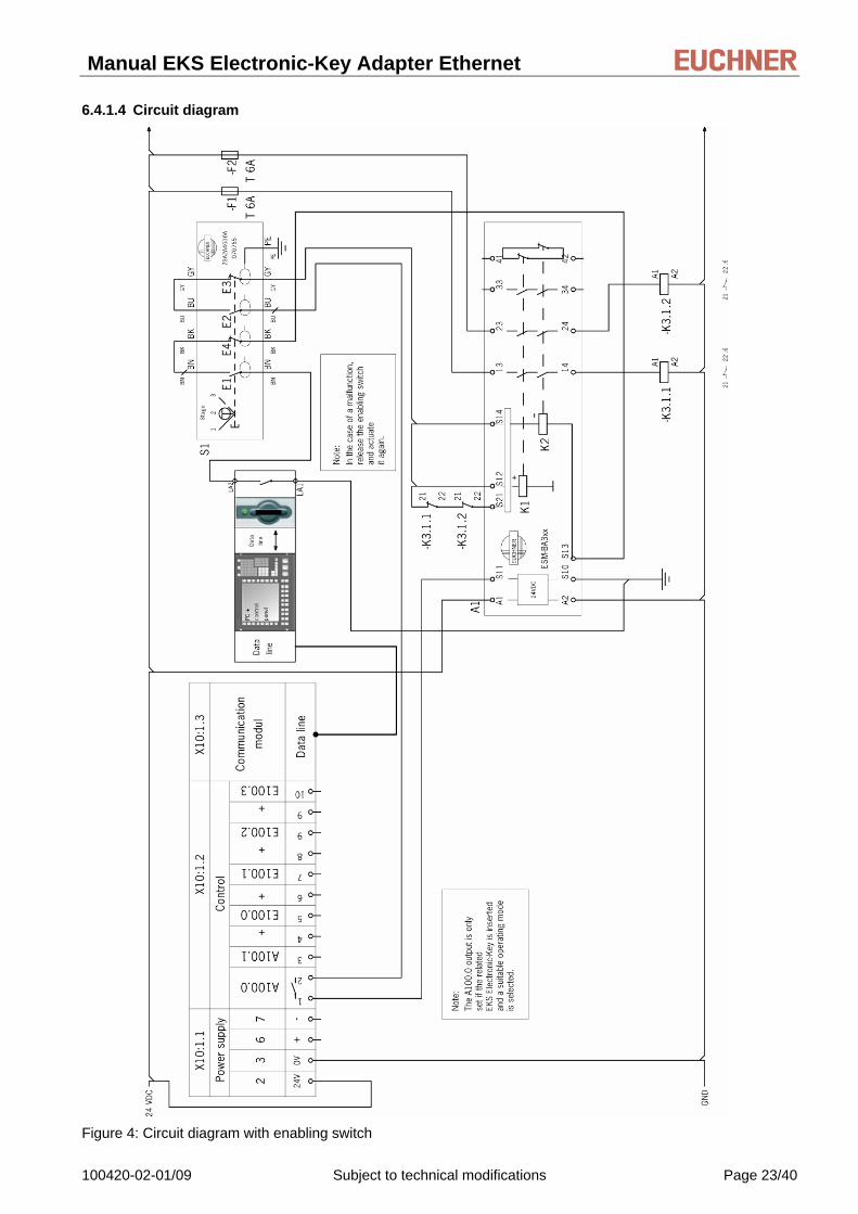
6.4.1.4 Circuit diagram
Figure 4: Circuit diagram with enabling switch
100420-02-01/09 Subject to technical modifications Page 23/40

Manual EKS Electronic-Key Adapter Ethernet
6.4.2 Connection example without enabling switch
Figure 5: Principle of operation (illustration with selected operating mode and all parts in actuated position)
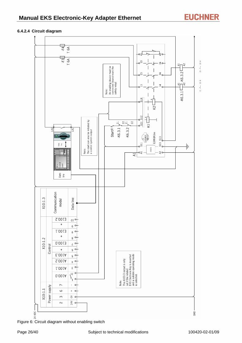
6.4.2.1 Description of the application example without enabling switch
The danger area on a machine is secured with a fence. To make set-up work on the machine possible with the guard open, an EKS FSA system is integrated in conjunction with a control system and a safety relay. The safety relay must comply with the following requirements:
Detection of short-circuits and earth faults. A short-circuit can be detected in the safety path in the circuit described due to the fact that both the positive path and earth path of the safety relay are switched. In this case, the safety relay deactivates its safety outputs.
Simultaneity monitoring: the safety relay must detect whether the safety inputs are switched practically simultaneously. If this is not the case, the safety outputs are not switched and the unit switches to fault state. A renewed start is possible only after the key has been inserted again.
Start button monitoring: the safety relay must detect when the start button is welded or jammed at the latest at the next start. If this is the case, the safety outputs are not switched and the unit switches to fault state. This prevents accidental starting of the system.
The switching contact LA1/LA2 is closed after insertion of the Electronic-Key. The EKS FSA is coupled with a PC. After the insertion of the Electronic-Key, the PC checks whether the key is authorized for work in the selected operating mode. If this is not the case, the operating mode cannot be set. If suitable access rights are available, the control system gives the instruction to the switching contact A100.0 to close.
The switching contact LA1/LA2 of the EKS FSA is connected to the first input on the safety relay. The switching contact A100.0 on the control system is connected to the second input on the safety relay. The control contact A100.0 and the switching contact LA1/LA2 are monitored for simultaneity.
Page 24/40 Subject to technical modifications 100420-02-01/09

Manual EKS Electronic-Key Adapter Ethernet
The safety relay is de-energized without a time delay (stop category 0) and the machine movement is stopped if
the Electronic-Key is removed or
the machine control system cancels the release (switching contact A100.0 is opened).
Note: The switching contact A100.0 is only allowed to be set if
the related Electronic-Key is inserted and
a suitable operating mode is selected.
6.4.2.2 Feedback loop
The safety relay can be started only with the feedback loop closed. A welded contactor contact in the enable path will thus be detected when a start request is made and a start is then prevented. The power contactor must have positively driven contacts.
6.4.2.3 Start
The safety relay start takes place after release by the EKS FSA and by the control and after operation of the start button.
100420-02-01/09 Subject to technical modifications Page 25/40
Manual EKS Electronic-Key Adapter Ethernet
6.4.2.4 Circuit diagram
Figure 6: Circuit diagram without enabling switch
Page 26/40 Subject to technical modifications 100420-02-01/09

Manual EKS Electronic-Key Adapter Ethernet
7 Setup Perform setup in the following sequence:
1. Set the DIP switches on the Electronic-Key adapter (see section 4.4).
2. Check mounting and electrical connection are correct (see section 5 and section 6).
3. After connection of the power supply, the LED on the front of the Electronic-Key adapter first illuminates red. When the connection has been established, the LED illuminates green and signals readiness for operation.
4. Insert Electronic-Key in the Electronic-Key adapter . The LED changes to yellow.
5. Important: for the version EKS FSA, all safety functions must also be thoroughly tested.
7.1 Network settings You need the following information to integrate the EKS Electronic-Key adapter into the network:
IP address of the host computer with which you want to configure the Electronic-Key adapter .
Free IP address that can be assigned to the EKS Electronic-Key adapter (not needed if the IP address is obtained automatically from a DHCP server)
Subnet mask of the network in which the Electronic-Key adapter is to be operated
If necessary, information on valid gateway
If necessary, information on valid DNS server
Information! The TCP connection to the Electronic-Key adapter must be made using port 2444. If the Ethernet ActiveX® module is used, this port is set by default. If the connection, e. g., is to be made from a control system, this port must be set explicitly.
7.1.1 Network settings for a configuration PC with Windows® XP
Information! It is assumed that you perform initial setup of the EKS Electronic-Key adapter using a configuration PC as shown in the following example.
For connection, you need a (Cat5) patch cable with crossed wires (crossover).
You must first adapt the network settings so that the device can be found in the network (see section 7.1).
Figure 7: Connection of configuration PC
100420-02-01/09 Subject to technical modifications Page 27/40
Manual EKS Electronic-Key Adapter Ethernet
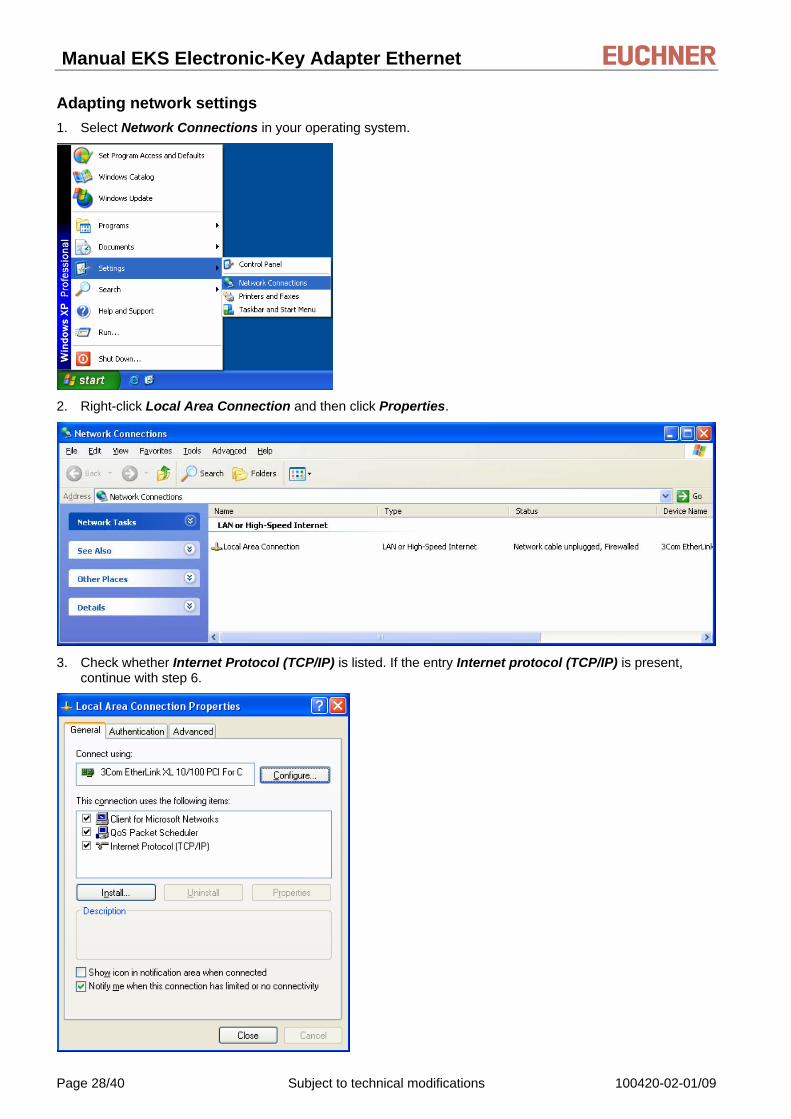
Adapting network settings 1. Select Network Connections in your operating system.
2. Right-click Local Area Connection and then click Properties.
3. Check whether Internet Protocol (TCP/IP) is listed. If the entry Internet protocol (TCP/IP) is present,
continue with step 6.
Page 28/40 Subject to technical modifications 100420-02-01/09

Manual EKS Electronic-Key Adapter Ethernet
4. Click Install. The Select network component type dialog box opens. Click Protocol and then click the Add button. The Select network protocol dialog box opens.
5. In the Select network protocol dialog box, select the entry Microsoft TCP/IP and click OK. You may need the installation CD of Windows® XP to set this up.
6. In the Local Area Connection Properties dialog box, double-click the entry Internet Protocol TCP/IP. The Internet Protocol (TCP/IP) Properties dialog box opens.
7. In order to ensure that the EKS Electronic-Key adapter and the configuration computer are in the same network, you must assign your configuration PC an IP address in the same subnet mask as the Electronic-Key adapter . On delivery, the default IP of the Electronic-Key adapter is 192.168.1.1 and the subnet mask is 255.255.255.0. This means that you can assign the configuration computer an arbitrary IP address between 192.168.1.2 and 192.168.1.254. In this example, the configuration PC is assigned the IP address 192.168.1.2.
8. Click the OK button to confirm your inputs.
The EKS Electronic-Key adapter can now be configured via the integrated web interface as described in section 7.2.
100420-02-01/09 Subject to technical modifications Page 29/40

Manual EKS Electronic-Key Adapter Ethernet
7.2 Configuring the Electronic-Key adapter via the web interface The Electronic-Key adapter can be configured with a web browser.
If you wish to operate the Electronic-Key adapter with a self-defined, fixed IP address, it is recommended to configure the device with a PC. This is the fastest method, particularly if several devices have to be configured. The configuration PC must meet the following requirements:
Network card (10Base-T or 100Base-TX)
Web browser (e.g. Internet Explorer)
Java and Java Script must be activated in the security settings of the browser.
Java Runtime Environment in Version 1.5.0 or higher must be installed.
If the configuration PC features a firewall, it may be necessary to enable the EKS Electronic-Key adapter as a trustworthy application. Refer to the firewall documentation for further information.
Launching the EKS web interface
1. Open a browser window and enter the default IP address (http://192.168.1.1) of the EKS Electronic-Key adapter or the IP address you have assigned. If the EKS Electronic-Key adapter is located in a network with DHCP server, enter the automatically assigned IP address. You will find this in the network connection properties under Windows® XP.
The Information screen of the EKS web interface is now displayed.
Page 30/40 Subject to technical modifications 100420-02-01/09

Manual EKS Electronic-Key Adapter Ethernet
2. Click Configuration.
The Configuration screen of the EKS web interface is now displayed.
1. Enter the desired IP address and the subnet mask. If the network has a gateway, also enter this information.
2. Click the Send button.
The following message is displayed: The settings were saved, to apply settings please switch power off/on…
3. Interrupt the power supply and connect the Electronic-Key adapter again in order to activate the settings.
Information! The DIP switches S3.1, S3.2, S3.3 and S3.4 must all be set to OFF, so that settings can be made via the web interface (see DIP switch settings in section 4.4.3).
100420-02-01/09 Subject to technical modifications Page 31/40
Manual EKS Electronic-Key Adapter Ethernet
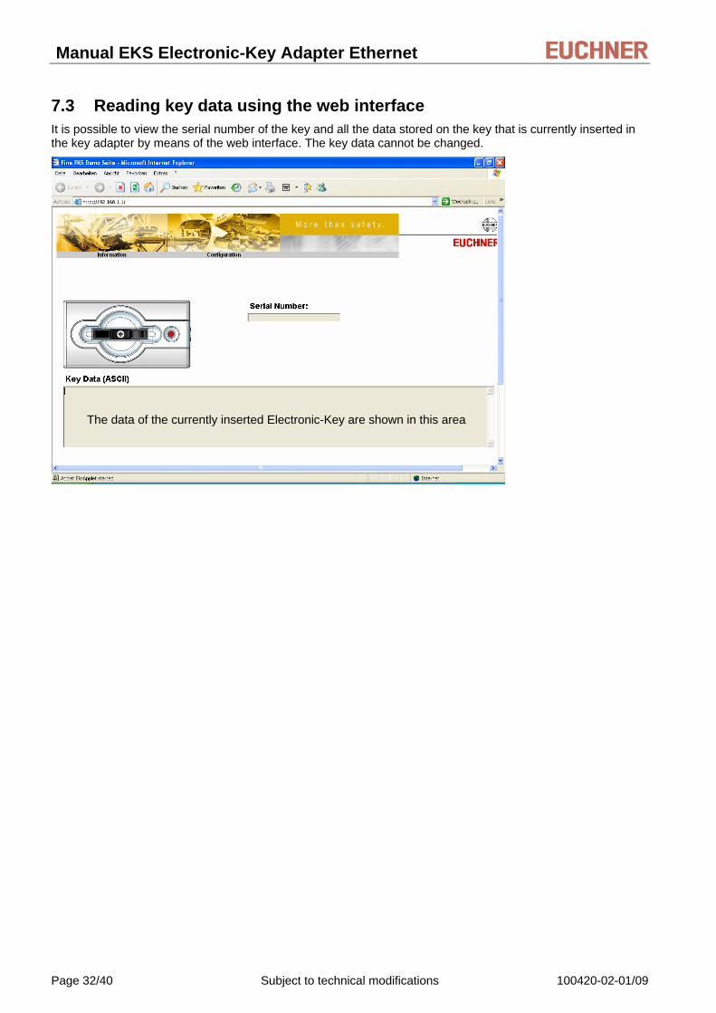
7.3 Reading key data using the web interface It is possible to view the serial number of the key and all the data stored on the key that is currently inserted in the key adapter by means of the web interface. The key data cannot be changed.
The data of the currently inserted Electronic-Key are shown in this area
Page 32/40 Subject to technical modifications 100420-02-01/09

Manual EKS Electronic-Key Adapter Ethernet
8 Data transfer via the Ethernet interface
8.1 Communication This section primarily describes communication between a PC and the Electronic-Key adapter (referred to as the device in the following).
The commands
Program (write) Electronic-Key
Read Electronic-Key
are transferred via TCP/IP.
Integration of the Electronic-Key adapter with Ethernet interface into the user’s PC application is supported by an optionally available ActiveX® module (order no. 100 665) (usable for MS Windows® based programs with ActiveX® capability). EKS can thus be used in conjunction with process visualization. The ActiveX® module is used as a protocol driver for the TCP/IP data transfer protocols described in the following.
Euchner provides a shared library as the interface to the NCU control system of the SINUMERIK Solution Line (Embedded Linux).
Information!
EKS is used in read-only mode in this system environment.
In order to avoid problems caused by parallel use of the TCP/IP interface and the web server, the number of simultaneous connections is limited to one.
8.2 Basic message structure
8.2.1 IP – Internet Protocol The internet protocol defines the basis for data transfer. It guarantees data transfer by connectionless, unsecured transport of data packets. IP provides an addressing mechanism in order to unambiguously identify the sender and receiver. This is done by means of IP addresses.
In addition to the actual user data that are to be transferred, a data packet also contains other important information to facilitate problem-free data transfer. This additional information is also referred to as the packet overhead or header.
8.2.2 TCP – Transport Control Protocol TCP takes care of the handling and security of the IP data packets. It establishes a connection between two network stations for the duration of data transfer. The conditions for data transfer (e.g. the size of the data packets) are defined when the connection is set up. TCP operates according to the so-called client-server principle. The network station that sets up a connection represents the client. The addressed network station is known as the server.
TCP provides every data packet with a checksum and therefore ensures that any data loss is detected. A sequence number is also transferred that calculates a so-called acknowledge number according to a fixed algorithm. This acknowledge number is sent back to the sender. In this way, the receiver acknowledges that the data packet has been received correctly. If this is not the case, the receiver requests the data packet again.
A further task of TCP is forwarding of data packets to the correct application. These applications (so-called services) are addressed by means of different port numbers (e.g. port 80 for HTTP).
100420-02-01/09 Subject to technical modifications Page 33/40

Manual EKS Electronic-Key Adapter Ethernet
8.3 Commands for writing and reading a read/write Electronic-Key Write and read processes are always initiated by the PC/control system using a "command message".
The command message and reply message are also packed as user data in the TCP/IP frame.
The Electronic-Key system then sends a reply message to the PC/control system.
PC/Control system Electronic-Key-System
Command message ⎯⎯⎯⎯⎯⎯⎯⎯⎯→
Reply message ←⎯⎯⎯⎯⎯⎯⎯
Information!
On read/write Electronic-Keys with 116 bytes, the memory is organized in 4-byte blocks. This means a multiple of 4-byte sized blocks must always be written.
The start address must be given in the range byte number 0 to byte number 112, always in 4-byte steps (byte number 0, 4, 8 ... 112)!
However, during reading it is possible to access the memory by bytes without the above mentioned restriction for writing.
Page 34/40 Subject to technical modifications 100420-02-01/09

Manual EKS Electronic-Key Adapter Ethernet
8.3.1 Write process
Information!
When this command is used, the Electronic-Key must be in the Electronic-Key adapter and is only allowed to be removed from within the operating distance after reception of the reply message.
Command message (message core, PC/PLC (control system) → EKS, see Figure 8):
TP (device addr.) (start addr. user data) (number of bytes of user data) (user data)
Reply message (message core, EKS → PC/PLC (control system), see Figure 9):
RF (device addr.) (00hex, 00hex) (status number)
Content Byte no. Description ASCII hexadecimal decimal
0 Number of message bytes 0B ... 7B 11 ... 123 1 2 Command identification T
P 54 50
84 80
3 Device address 01 1 4 5 Start address for user data 00
00 ... 70 0
0 ... 112 6 Number of bytes of user data 04 ... 74 4 ... 116
7 ... 122 User data ASCII or hexadecimal or BCD (code transparent)
Figure 8: Command message write Electronic-Key read/write (message core)
Content Byte no. Description ASCII hexadecimal decimal
0 Number of message bytes 07 7 1 2 Command identification R
F 52 46
82 70
3 Device address 01 1 4 5 Padding data 00
00 0 0
6 Status number *
Figure 9: Reply message write Electronic-Key read/write - status (message core)
* Status number 00hex: No error
02hex: Electronic-Key not in the operating distance
(For further status numbers see section 8.5)
100420-02-01/09 Subject to technical modifications Page 35/40

Manual EKS Electronic-Key Adapter Ethernet
8.3.2 Read process Command message (message core, PC/PLC (control system) → EKS, see Figure 10):
TL (device addr.) (start addr. user data) (number of bytes of user data)
Reply message (message core, EKS → PC/PLC (control system), see Figure 11 or Figure 12):
For this command there are two possible replies:
RL (device addr.) (start addr. user data) (number of bytes of user data) (user data)
or
RF (device addr.) (00hex, 00hex) (status number)
The reply message RL (see Figure 11) stands for correct reception of the data.
If an Electronic-Key cannot be read, an RF reply message is received (see Figure 12). The status number then indicates the cause of the error.
Content Byte no. Description ASCII hexadecimal decimal
0 Number of message bytes 07 7 1 2 Command identification T
L 54 4C
84 76
3 Device address 01 1 4 5 Start address for user data 00
00 ... 73 0
0 ... 115 6 Number of bytes of user data 01 ... 74 1 ... 116
Figure 10: Command message read Electronic-Key read/write (message core)
Content Byte no. Description ASCII hexadecimal decimal 0 Number of message bytes 08 ... 7B 8 ... 123 1 2 Command identification R
L 52 4C
82 76
3 Device address 01 1 4 5 Start address for user data 00
00 ... 73 0
0 ... 115 6 Number of bytes of user data 01 ... 74 1 ... 116
7 ... 122 User data ASCII or hexadecimal or BCD (code transparent)
Figure 11: Reply message read Electronic-Key read/write (message core)
Content Byte no. Description ASCII hexadecimal decimal 0 Number of message bytes 07 7 1 2 Command identification R
F 52 46
82 70
3 Device address 01 1 4 5 Padding data 00
00 0 0
6 Status number *
Figure 12: Reply message read Electronic-Key read/write - status (message core)
* Status number 02hex: Electronic-Key not in the operating distance
(For further status numbers see section 8.5)
Page 36/40 Subject to technical modifications 100420-02-01/09
Manual EKS Electronic-Key Adapter Ethernet
8.3.3 Reading the serial number The Electronic-Key read/write contains a unique 8-byte serial number. This number is written by laser during the Electronic-Key production process and can never be changed or deleted. The serial number is used for secure distinction of every single Electronic-Key. It is necessary that all 8 bytes are completely evaluated for reliable differentiation. The serial number is appended to the freely programmable user data.
The serial number can be read by entering the start address byte number 116 and the number of bytes 8 (see section 8.3.2).
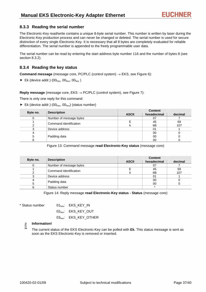
8.3.4 Reading the key status Command message (message core, PC/PLC (control system) → EKS, see Figure 6):
Ek (device addr.) (00hex, 00hex, 00hex )
Reply message (message core, EKS → PC/PLC (control system), see Figure 7):
There is only one reply for this command:
Ek (device addr.) (00hex, 00hex) (status number) Content Byte no. Description ASCII hexadecimal decimal
0 Number of message bytes 07 7 1 2 Command identification E
k 45 6B
69 107
3 Device address 01 1 4 5 6
Padding data 00 00 00
0 0 0
Figure 13: Command message read Electronic-Key status (message core)
Content Byte no. Description ASCII hexadecimal decimal 0 Number of message bytes 07 7 1 2 Command identification E
k 45 6B
69 107
3 Device address 01 1 4 5 Padding data 00
00 0 0
6 Status number *
Figure 14: Reply message read Electronic-Key status - Status (message core)
* Status number 01hex: EKS_KEY_IN
02hex: EKS_KEY_OUT
03hex: EKS_KEY_OTHER
Information!
The current status of the EKS Electronic-Key can be polled with Ek. This status message is sent as soon as the EKS Electronic-Key is removed or inserted.
100420-02-01/09 Subject to technical modifications Page 37/40

Manual EKS Electronic-Key Adapter Ethernet
8.4 Command overview Description Command message Reply message Program (write) Electronic-Key TP (see section 8.3.1) RF (see section 8.3.1) Read Electronic-Key (also read the serial number)
TL (see sections 8.3.2 and 8.3.3) RL (see section 8.3.2) or RF (see section 8.3.2)
Reading the key status Ek (see section 8.3.4) Ek (see section 8.3.4)
8.5 Status numbers Value Description 00hex No error 02hex Electronic-Key not in the operating distance 03hex Parity bit error on read-only Electronic-Key 06hex Write process aborted. Start address or number of bytes is not a multiple of the block size 4
17hex Read attempt when the Electronic-Key adapter is set to read/write Electronic-Key and a read-only Electronic-Key is inserted
18hex Read attempt when the Electronic-Key adapter is set to read-only Electronic-Key and a read/write Electronic-Key is inserted
4xhex General Electronic-Key communication error (renewed write or read necessary) 50hex Write attempt despite enabled write protection
Page 38/40 Subject to technical modifications 100420-02-01/09

Manual EKS Electronic-Key Adapter Ethernet
9 Exclusion of liability Exclusion of liability under the following conditions:
if the device is not used for its intended purpose
non-compliance with safety regulations
if mounting and electrical connection are carried out by unauthorized personnel
if modifications are made
10 Service and repair No servicing is required.
Remove dirt from the Electronic-Key and the Electronic-Key adapter using a soft cloth and solvent-free, non-abrasive cleaning agents.
Repairs must be performed only by the manufacturer.
On version EKS FSA devices, the safety-related functions must be checked at regular intervals.
11 Guarantee The "General Terms and Conditions" of EUCHNER GmbH + Co. KG apply.
100420-02-01/09 Subject to technical modifications Page 39/40

Manual EKS Electronic-Key Adapter Ethernet
Microsoft Windows® and ActiveX® are registered trademarks of Microsoft Corporation
EUCHNER GmbH + Co. KG Phone +49 (0)711 / 75 97 - 0 Kohlhammerstraße 16 Fax +49 (0)711 / 75 33 16 D-70771 Leinfelden-Echterdingen www.euchner.de . [email protected]