Embed Size (px)
Citation preview
ELECTRONIC DIESEL ENGINEDIAGNOSIS SPECIALIST TEST (L2)
MEDIUM/HEAVYCOMPOSITE VEHICLE TYPE 3
REFERENCE BOOKLET
This booklet is intended only for reference when preparing for and taking the ASE Electronic Diesel Engine Diagnosis Specialist (L2) Test. The medium/heavy composite vehicle control system is based on designs common to many engine and vehicle manufacturers, but is not identical to any actual production engine or vehicle.
Page 2 ASE Medium/Heavy Composite Vehicle Type 3 Reference Booklet
— MEDIUM/HEAVY COMPOSITE VEHICLE INFORMATION —
GENERAL DESCRIPTION This generic in-line six cylinder diesel engine is equipped with a variable geometry turbocharger (VGT), charge air cooler (CAC), electronic unit injectors (EUI), closed crankcase ventilation, exhaust gas recirculation (EGR), and exhaust aftertreatment system. The engine rating is 400 hp at 1,800 rpm and develops a peak torque of 1450 lb. ft. at 1,200 rpm.
THE ELECTRONIC CONTROL MODULE (ECM) The electronic control module is the microprocessor that receives electronic inputs from sensors and switches, and is calibrated to control fuel metering, injection timing, diagnostics, and engine protec-tion. The ECM receives power from the battery and ignition switch and provides a reference voltage for some sensors. The software contained in the ECM determines how the electronic diesel engine control system operates. The ECM stores the calibration values that define rated horsepower, torque curves, and rpm specifications. The engine ECM communicates with other vehicle system control modules through the SAE J1939 data link (controller area network - CAN). The ECM is mounted on the engine.
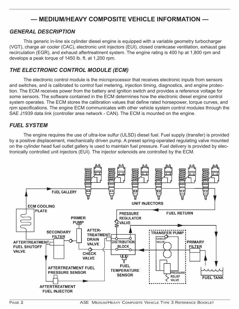
FUEL SYSTEM The engine requires the use of ultra-low sulfur (ULSD) diesel fuel. Fuel supply (transfer) is provided by a positive displacement, mechanically driven pump. A preset spring-operated regulating valve mounted on the cylinder head fuel outlet gallery is used to maintain fuel pressure. Fuel delivery is provided by elec-tronically controlled unit injectors (EUI). The injector solenoids are controlled by the ECM.
ASE Medium/Heavy Composite Vehicle Type 3 Reference Booklet Page 3
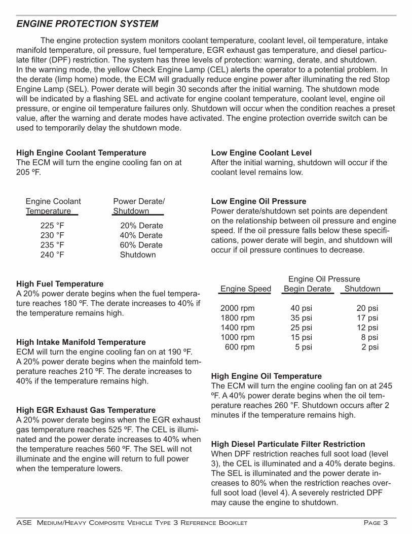
ENGINE PROTECTION SYSTEM The engine protection system monitors coolant temperature, coolant level, oil temperature, intake manifold temperature, oil pressure, fuel temperature, EGR exhaust gas temperature, and diesel particu-late filter (DPF) restriction. The system has three levels of protection: warning, derate, and shutdown.In the warning mode, the yellow Check Engine Lamp (CEL) alerts the operator to a potential problem. In the derate (limp home) mode, the ECM will gradually reduce engine power after illuminating the red Stop Engine Lamp (SEL). Power derate will begin 30 seconds after the initial warning. The shutdown mode will be indicated by a flashing SEL and activate for engine coolant temperature, coolant level, engine oil pressure, or engine oil temperature failures only. Shutdown will occur when the condition reaches a preset value, after the warning and derate modes have activated. The engine protection override switch can be used to temporarily delay the shutdown mode.
High Engine Coolant TemperatureThe ECM will turn the engine cooling fan on at 205 ºF.
Engine Coolant Power Derate/Temperature Shutdown
225 °F 20% Derate 230 °F 40% Derate 235 °F 60% Derate 240 °F Shutdown
High Fuel TemperatureA 20% power derate begins when the fuel tempera-ture reaches 180 ºF. The derate increases to 40% if the temperature remains high.
High Intake Manifold TemperatureECM will turn the engine cooling fan on at 190 ºF. A 20% power derate begins when the mainfold tem-perature reaches 210 ºF. The derate increases to 40% if the temperature remains high.
High EGR Exhaust Gas TemperatureA 20% power derate begins when the EGR exhaust gas temperature reaches 525 ºF. The CEL is illumi-nated and the power derate increases to 40% when the temperature reaches 560 ºF. The SEL will not illuminate and the engine will return to full power when the temperature lowers.
Low Engine Coolant Level After the initial warning, shutdown will occur if the coolant level remains low.
Low Engine Oil PressurePower derate/shutdown set points are dependent on the relationship between oil pressure and engine speed. If the oil pressure falls below these specifi-cations, power derate will begin, and shutdown will occur if oil pressure continues to decrease.
Engine Oil PressureEngine Speed Begin Derate Shutdown
2000 rpm 40 psi 20 psi1800 rpm 35 psi 17 psi1400 rpm 25 psi 12 psi1000 rpm 15 psi 8 psi 600 rpm 5 psi 2 psi
High Engine Oil TemperatureThe ECM will turn the engine cooling fan on at 245 ºF. A 40% power derate begins when the oil tem-perature reaches 260 °F. Shutdown occurs after 2 minutes if the temperature remains high.
High Diesel Particulate Filter RestrictionWhen DPF restriction reaches full soot load (level 3), the CEL is illuminated and a 40% derate begins. The SEL is illuminated and the power derate in-creases to 80% when the restriction reaches over-full soot load (level 4). A severely restricted DPF may cause the engine to shutdown.
Page 4 ASE Medium/Heavy Composite Vehicle Type 3 Reference Booklet
SENSORSAccelerator Pedal Position Sensor (APP) - The APP contains two potentiometers that sense the position of the accelerator pedal. A reference voltage is sent to each potentiometer and as the angle of the accelerator pedal changes, the APP varies the signal voltages to the ECM. Both APP potentiometer voltages are compared by the ECM for diagnostics. If one or both of the signals are lost, the engine will not operate above idle speed.
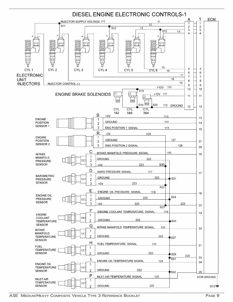
Engine Oil Pressure Sensor (EOP) - The variable capacitance EOP sensor monitors engine oil pressure and is installed in the main lube oil gallery. The ECM uses this signal for engine protection and the instrument panel pressure gauge.
Intake Manifold Pressure Sensor (IMP) - The variable capacitance IMP sensor monitors intake manifold pressure and is located on the intake manifold. The ECM uses this signal to control fuel metering, injection timing, and turbocharger control.
Intake Manifold Temperature Sensor (IMT) - The thermistor IMT sensor monitors air temperature in the intake manifold. The ECM uses this signal to control fuel metering, injection timing, EGR operation, engine protection, and cooling fan operation.
Barometric Pressure Sensor (BARO) - The variable capacitance BARO sensor monitors ambient air pressure. The ECM uses this signal to adjust injection timing and fuel metering based on altitude.
Engine Coolant Temperature Sensor (ECT) - The thermistor ECT sensor monitors coolant temperature and is mounted in the engine block coolant jacket. The ECM uses this signal to control fuel management, engine protection, cooling fan operation, the instrument panel temperature gauge, and DPF regeneration.
Coolant Level Sensor (CLS) - The CL sensor monitors the level of the coolant in the radiator surge tank. The ECM uses this signal for engine protection when coolant is not detected.
Fuel Temperature Sensor (FTS) - The thermistor FT sensor monitors fuel temperature and is mounted on the fuel distribution block. The ECM uses this signal to adjust calculated fuel measurements to compensate for changes in fuel temperature and for engine protection.
Engine Oil Temperature Sensor (EOT) - The thermistor EOT sensor monitors engine oil temperature and is installed in the main lube oil gallery. The ECM uses this signal for engine protection.
Inlet Air Temperature Sensor (IAT) - The thermistor IAT sensor monitors air temperature in the inlet pipe before the turbocharger. The ECM uses this signal for fuel management.
Engine Position Sensor 1 (EPS1) - The Hall-effect EPS1 generates a digital signal that varies in frequency with the speed of the engine camshaft. The ECM uses the frequency and pulse width of this signal to determine camshaft position for fuel control and injection timing. The ECM will use this signal for calculated engine speed in the event of EPS2 (crankshaft) signal failure. The engine will shutdown in the event of EPS1 (camshaft) signal failure. The EPS1 is located in the engine front cover facing the trigger/tone wheel that is mounted on the camshaft gear.
ASE Medium/Heavy Composite Vehicle Type 3 Reference Booklet Page 5
Engine Position Sensor 2 (EPS2) - The Hall-effect EPS2 generates a digital signal that varies in fre-quency with the speed of the engine crankshaft. The ECM uses the frequency of this signal to determine engine speed for fuel control and injection timing. The ECM requires input from both EPS1 and EPS2 for starting. The EPS2 is located in the engine rear flywheel housing facing the trigger/tone wheel mounted on the crankshaft.
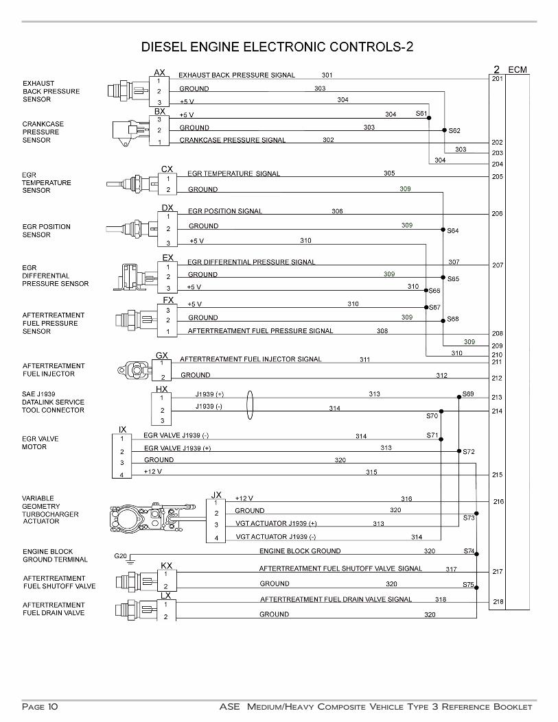
Exhaust Back Pressure Sensor (EBP) - The variable capacitance EBP sensor monitors exhaust gas pressure from a tube connected to the exhaust manifold. The ECM uses this signal for EGR valve and variable geometry turbocharger (VGT) operation.
Crankcase Pressure Sensor (CPS) - The variable capacitance CP sensor monitors pressure in the en-gine crankcase. The ECM uses this signal to verify the condition of the closed crankcase ventilation sys-tem and filter.
EGR Temperature Sensor (EGRT) - The thermistor EGRT sensor monitors the temperature of the ex-haust gases in the outlet of the EGR cooler. The ECM uses this signal for emissions management and engine protection.
EGR Differential Pressure Sensor (EGR Delta P) - The variable capacitance EGR Delta P sensor has two ports that monitor the exhaust gas pressure across the EGR differential pressure orifice. One port is located on each side of the EGR venturi. The ECM uses this pressure drop signal and the EGR tempera-ture signal to calculate the amount of EGR flow into the intake manifold. The ECM commands the EGR valve and the VGT actuator positions to control the amount of exhaust gases entering the engine.
EGR Position Sensor (EGRP) - The three-wire fixed potentiometer EGRP sensor monitors the position of the EGR valve. The ECM uses this signal to verify proper operation of the EGR valve and motor for emis-sions control and diagnostics.
Ambient Air Temperature Sensor (AT) - The thermistor AT sensor monitors the outside (ambient) air temperature and is mounted on the cab. The signal is sent from the body control module (BCM) to the ECM through the J1939 data link (CAN). The ECM uses this temperature for idle shutdown operation.
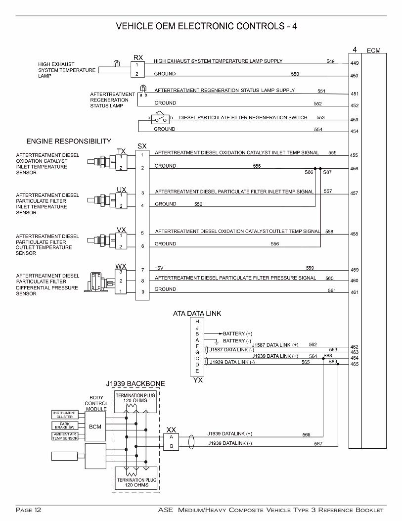
Aftertreatment Fuel Pressure Sensor (AFP) - The variable capacitance AFP sensor monitors the pres-sure in the aftertreatment fuel system. The ECM uses this signal in determining operation of the aftertreat-ment fuel injector during regeneration. Active and stationary regeneration will be disabled if a fuel pressure fault is detected.
Aftertreatment Diesel Oxidation Catalyst Inlet Temperature Sensor (EGT1) - The thermistor aftertreat-ment diesel oxidation catalyst (DOC) inlet temperature sensor monitors the exhaust gas temperature into the (DOC). The ECM uses this signal to control EGR and VGT actuator positions and aftertreatment fuel injection during DPF regeneration.
Aftertreatment Diesel Particulate Filter Inlet Temperature Sensor (EGT2) - The thermistor aftertreat-ment diesel particulate filter (DPF) inlet temperature sensor monitors the exhaust gas temperature enter-ing the DPF. The ECM uses this signal in determining EGR and VGT actuator positions and aftertreatment fuel injection during DPF regeneration.
Page 6 ASE Medium/Heavy Composite Vehicle Type 3 Reference Booklet
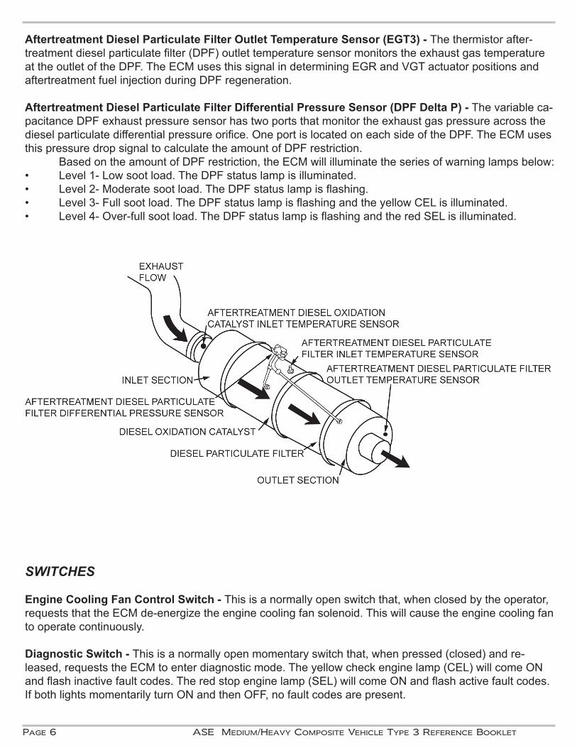
Aftertreatment Diesel Particulate Filter Outlet Temperature Sensor (EGT3) - The thermistor after-treatment diesel particulate filter (DPF) outlet temperature sensor monitors the exhaust gas temperature at the outlet of the DPF. The ECM uses this signal in determining EGR and VGT actuator positions and aftertreatment fuel injection during DPF regeneration. Aftertreatment Diesel Particulate Filter Differential Pressure Sensor (DPF Delta P) - The variable ca-pacitance DPF exhaust pressure sensor has two ports that monitor the exhaust gas pressure across the diesel particulate differential pressure orifice. One port is located on each side of the DPF. The ECM uses this pressure drop signal to calculate the amount of DPF restriction. Based on the amount of DPF restriction, the ECM will illuminate the series of warning lamps below: • Level 1- Low soot load. The DPF status lamp is illuminated.• Level 2- Moderate soot load. The DPF status lamp is flashing.• Level 3- Full soot load. The DPF status lamp is flashing and the yellow CEL is illuminated.• Level 4- Over-full soot load. The DPF status lamp is flashing and the red SEL is illuminated.
SWITCHES
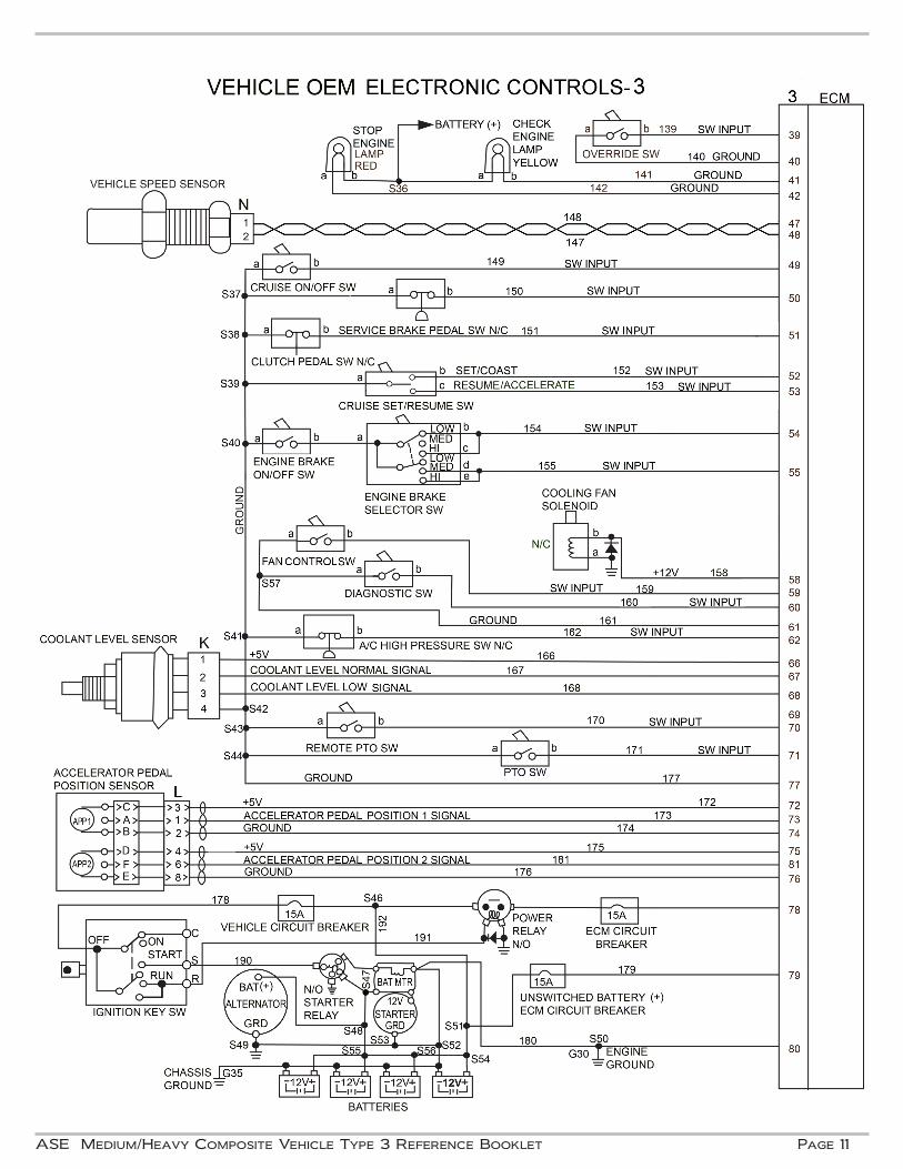
Engine Cooling Fan Control Switch - This is a normally open switch that, when closed by the operator, requests that the ECM de-energize the engine cooling fan solenoid. This will cause the engine cooling fan to operate continuously.
Diagnostic Switch - This is a normally open momentary switch that, when pressed (closed) and re-leased, requests the ECM to enter diagnostic mode. The yellow check engine lamp (CEL) will come ON and flash inactive fault codes. The red stop engine lamp (SEL) will come ON and flash active fault codes. If both lights momentarily turn ON and then OFF, no fault codes are present.
ASE Medium/Heavy Composite Vehicle Type 3 Reference Booklet Page 7
Air Conditioning High Pressure Switch - This normally closed pressure switch opens when the air conditioner high-side pressure reaches a preset value. This signals the ECM to operate the engine cooling fan.
Cruise Control On/Off Switch - This normally open switch enables cruise control operation when it is closed by the operator.
Cruise Set/Resume Switch - This switch has two momentary positions: SET/COAST and RESUME/ACCELERATE. Vehicle cruising speed can be set by pressing SET/COAST. Once a speed has been set, and then disengaged using the brake or clutch, the ECM will return to the previously set speed when RESUME/ACCELERATE is pressed. Vehicle cruise control set speed is adjusted lower by pressing SET/COAST and higher by pressing RESUME/ACCELERATE. The two set/resume switch positions are also used for engine speed settings during PTO operation.
Clutch Pedal Switch - This normally closed switch opens when the clutch pedal is depressed. This sig-nals the ECM to cancel cruise control, power take-off mode, or engine braking and to override the idle shutdown timer.
Service Brake Pedal Switch - This normally closed pressure switch opens when the service brake pedal is depressed. This signals the ECM to enable engine braking, cancel cruise control and power take-off mode, and to override the idle shutdown timer.
Engine Brake On/Off Switch - This normally open switch signals the ECM that the operator is requesting engine brake system activation when closed. The ECM will energize the engine brake solenoids based on inputs from the accelerator pedal and the cruise control on/off, clutch and service brake switches.
Engine Brake Selector Switch - This three-position switch sets the level of engine braking (LOW, MEDI-UM, or HIGH). The engine brake solenoid for engine cylinders 3 & 4 is energized for the LOW level. The engine brake solenoids for cylinders 1 & 2 and cylinders 5 & 6 are energized for the MEDIUM level. All three solenoids are energized for the HIGH engine braking level.
Power Take-Off (PTO) On/Off Switch - This normally open switch enables PTO mode operation when closed. In this mode, the cruise control set/resume switch is used for two preset PTO engine speeds. SET/COAST is pressed for the first engine speed setting and RESUME/ACCELERATE is pressed for the sec-ond setting.
Power Take-Off (PTO) Remote Switch - This normally open switch is mounted outside the cab and en-ables remote PTO mode operation at a preset engine speed when closed. Engine Protection Override Switch - This is a normally open momentary switch that, when pressed (closed) and released during the shutdown warning period, requests the ECM to override (delay) an en-gine protection shutdown for 30 seconds.
Diesel Particulate Filter Regeneration Switch - This normally open momentary switch that, when pressed (closed) and released, requests the ECM to enable a stationary or parked DPF regeneration.
Parking Brake Switch - This normally closed switch opens when the parking brake is released. The switch position signal is sent from the body control module (BCM) to the ECM through the J1939 data link (CAN). The ECM uses this input to control stationary or parked DPF regeneration, idle shutdown, and PTO operation.
Page 8 ASE Medium/Heavy Composite Vehicle Type 3 Reference Booklet
ACTUATORSElectronic Unit Injectors (EUI) - These electromechanical diesel fuel injectors contain a solenoid controlled by the ECM to manage fuel timing and metering. The ECM injector driver circuitry supplies high voltage to the injector solenoids which are energized by controlling the ground circuits within the ECM. Injector calibration codes need to be programmed into the ECM to compensate for manufacturing tolerances.
Engine Cooling Fan Solenoid - When energized by the ECM, this normally closed solenoid supplies air pressure to disengage the engine cooling fan clutch and turn the fan OFF. The solenoid can be de-energized by the ECM, shutting off air pressure to engage the fan clutch and turn the fan ON. The ECM engages the fan to assist with engine braking when the selector switch is in the HIGH position. The ECM will operate the fan for engine protection when coolant temperature reaches 205ºF, engine oil temperature at 245ºF, intake manifold temperature at 190ºF, and when the A/C high-pressure switch opens.
Stop Engine Lamp - The red stop engine lamp (SEL) illuminates when the engine protection system is in the derate and shutdown modes. The red SEL can also be used to read active fault “flash” codes when in the diagnostic mode.
Check Engine Lamp - The amber/yellow check engine lamp (CEL) illuminates when the engine protection system is in the warning mode, or when electronic control system failures are occurring and an active fault is present. The yellow CEL can also be used to read inactive fault “flash” codes when in the diagnostic mode. The CEL and SEL are used in combination with the aftertreatment regeneration status lamp (DPFR) for DPF restriction status and regeneration requirements. Engine Brake Solenoids - These three solenoids can be energized by the ECM to provide engine braking on two, four or all six cylinders. The engine brake can be activated during cruise control operation. The solenoids will be energized after the set speed has been exceeded or when the service brake pedal is depressed and the accelerator pedal is released. The ECM will not energize the solenoids when the clutch pedal is depressed.
EGR Valve Motor - The EGR valve stepper motor is mounted on the EGR valve and controlled by the ECM through the J1939 data link (CAN). Exhaust gases flow through the EGR cooler to the EGR valve and into a venturi (mixing chamber combining intake air and exhaust gas) at the intake manifold. The ECM will disable the EGR valve (default closed position) in the event of motor data link communication failure.
Variable Geometry Turbocharger Actuator - The VGT actuator is mounted on the turbocharger and controlled by the ECM through the J1939 data link (CAN). The actuator operates an internal sliding nozzle ring in the turbine housing. The sliding nozzle ring allows for control of turbine shaft speed and by regulating exhaust gas flow through the turbocharger. As the ring is moved from the open to the closed position, exhaust gas flow velocity increases. The actuator has self-diagnostic capabilities and has a preset default position in the event of actuator failure. The ECM calculates turbocharger shaft speed for displayed data and diagnostics.
(Actuator section continues after the following wiring diagrams.)
ASE Medium/Heavy Composite Vehicle Type 3 Reference Booklet Page 9
Page 10 ASE Medium/Heavy Composite Vehicle Type 3 Reference Booklet
ASE Medium/Heavy Composite Vehicle Type 3 Reference Booklet Page 11
Page 12 ASE Medium/Heavy Composite Vehicle Type 3 Reference Booklet
ASE Medium/Heavy Composite Vehicle Type 3 Reference Booklet Page 13
Idle Shutdown Timer (IST)
The idle shutdown feature reduces the amount of fuel burned and increases engine life by shutting down the engine after a period of engine idling with no driver activity. Thirty seconds before the shutdown oc-curs, the stop engine lamp flashes to alert the driver of an impending shutdown. The driver can override the shutdown by depressing the service brake, clutch, or accelerator pedals during the warning period. If the override is successful, the SEL will continue flashing for two minutes. The idle shutdown time period will restart when the idle condition is detected by the ECM.
Idle shutdown can interact with the PTO feature. It can cause the engine to shutdown when in PTO mode. If the idle shutdown percent load threshold is not exceeded, the engine will be shutdown.
The following conditions must be set for the idle shutdown timer to activate. Any change to one or more of these conditions will reset or disable the IST.
Enable Conditions for IST:• Engine is idling below 750 rpm. • Vehicle speed is 0 mph.• No active vehicle speed sensor diagnostic faults.• PTO/Remote PTO is operating below the percent load threshold. (Customer Programmable Parameters) • Ambient air temperature is between 40 °F and 80 °F (CAN message from body control module).
(Customer Programmable Parameters) • No active inlet air temperature sensor diagnostic faults. • Engine coolant temperature is above 140 °F.• No active engine coolant temperature sensor diagnostic faults.• Stationary diesel particulate filter (DPF) regeneration is inactive.• Accelerator pedal position is released (at idle).• Service brake pedal switch is closed.• Clutch pedal switch is closed.• Parking brake applied (CAN message from body control module).
EXHAUST AFTERTREATMENTHigh Exhaust System Temperature Lamp (HEST) - The (HEST) lamp is illuminated by the ECM when the exhaust gas temperatures monitored by EGT3 exceed 850 °F and vehicle speed is below 5 mph.
Aftertreatment Regeneration Status Lamp (DPFR) - The ECM illuminates the aftertreatment regener-ation status lamp when DPF restriction reaches set points based on the input from the DPF differential pressure sensor (DPF Delta P). This indicates the need for DPF regeneration based on the following levels:
• Level 1- Low soot load. The DPFR status lamp is illuminated.• Level 2- Moderate soot load. The DPFR status lamp is flashing.• Level 3- Full soot load. The DPFR status lamp is flashing and CEL is illuminated.• Level 4- Over-full soot load. The DPFR status lamp is flashing and the SEL is illuminated.
Page 14 ASE Medium/Heavy Composite Vehicle Type 3 Reference Booklet
Aftertreatment Fuel Injector (AFI) - Fuel transfer pressure is supplied to the pulse width modulated (PWM) aftertreatment fuel injector from a shutoff valve located on the secondary fuel filter outlet. The ECM injects diesel fuel into the exhaust gas, upstream of the diesel oxidation catalyst (DOC), to raise the tem-perature. When DOC inlet temperature is 600 °F, the ECM begins operating the AFI and the duty cycle is varied until the exhaust temperature increases to the desired level for regeneration.
Aftertreatment Fuel Shutoff Valve (AFS) - The AFS controls the fuel flow to the supply valve on the secondary fuel filter housing when commanded by the ECM. After startup and during the first minute of engine operation, the ECM performs a self-test on the system by opening the AFS to pressurize the after-treatment fuel system. The AFD is then opened to relieve the fuel pressure while the ECM monitors the AFP sensor readings. The ECM will disable active and stationary regeneration until the next key cycle if a problem is detected.
Aftertreatment Fuel Drain Valve (AFD) - The AFD valve is used to maintain and relieve the fuel pressure in the aftertreatment fuel system. The ECM commands the AFD to open and allow fuel to flow into the fuel return line.
Aftertreatment Regeneration System Operation - The aftertreatment diesel particulate filter accumu-lates soot and ash during engine operation. Soot is oxidized and removed during regeneration. Ash ac-cumulates in the DPF over the service life of the unit. The DPF needs to be disassembled and the ash is removed by a special cleaning process. Regeneration is passive or active based on engine operating conditions, DPF restriction level, and driver’s response requirement. The ECM will not enable active or stationary regeneration if the DPF re-striction is at Level 4. Passive regeneration occurs when the exhaust temperatures are high enough through normal en-gine operation. This typically happens when the vehicle is driven at highway speeds and/or under heavy loads. Active regeneration occurs when the exhaust temperatures are not high enough to oxidize the soot collected in the DPF. This will occur more frequently in vehicles with low speed and low load duty cycles. The ECM will inject diesel fuel into the exhaust gas before the inlet of the diesel oxidation catalyst (DOC) to raise the temperature for regeneration. The ECM will enable and disable active regeneration as need-ed. The speed threshold for active regeneration to take place is 25 mph and it will stop when the vehicle speed drops below it. The exhaust temperature during active regeneration can reach up to 1,500 °F. Stationary (Parked) regeneration is needed when conditions are not reached during vehicle oper-ation. This is a form of active regeneration initiated by the operator using the DPF Regeneration Switch when the vehicle is not moving. The vehicle must be parked with the transmission in NEUTRAL and the parking brake set. There can be no input from the accelerator, brake, and clutch pedals. The ECM controls the regeneration process that can last up to 1 ½ hours depending on the amount of DPF restriction.
ASE Medium/Heavy Composite Vehicle Type 3 Reference Booklet Page 15
DATA LINK COMMUNICATIONS
The SAE J1939 data link bus (controller area network - CAN) allows the ECM to communicate with other vehicle control systems such as transmission, automatic traction control, antilock brake, and body controllers. The J1939 data link is an unshielded twisted pair (UTP). The ECM will broadcast public data link messages when the key switch is in the ON position and stops when the key switch is OFF. The ECM will also broadcast private data link messages to drive actuators using J1939 protocol during engine operation and diagnostic programming. The Society of Automotive Engineers (SAE) recommends a max-imum backbone harness of 131 feet (40 meters) in length. The harness is terminated at each end with a 120 ohm resistor. Up to 30 different devices can be attached to the J1939 backbone harness at one time. Each device is connected to the backbone harness with a 3 pin stub connector and can be a maximum of 3.3 feet (1 meter) in length. Any of the following conditions will cause the data communications bus to fail and result in the stor-age of network DTCs: either data line shorted to power, to ground, or to the other data line. The data bus will remain operational when one of the two modules containing a terminating resistor is not connected to the network. The data bus will fail when both terminating resistors are not connected to the network. Data communication failures do not prevent the ECM from providing fuel management. The Diagnostic Tool communicates with the ECM through the 9 pin ATA connector using J1708 pro-tocols over the J1939 and/or J1587 data links. This allows for diagnostic information retrieval and parame-ter calibration setting. The 9 pin ATA type data link connector is located in the cab.
DIAGNOSTIC TROUBLE CODES (DTC)
Trouble codes can be active or inactive. Active codes indicate that the problem currently exists and inactive codes indicate that a problem once existed. Flash codes represent digits assigned to diagnostic trouble codes, so that DTCs can be retrieved through the warning lamps when the diagnostic switch is ac-tivated. Active codes are indicated by the red stop engine lamp (SEL). Inactive codes are indicated by the yellow check engine lamp (CEL). When using the diagnostic tool, DTCs are formatted under SAE J1939 standards and descriptions.
DIAGNOSTIC EQUIPMENT
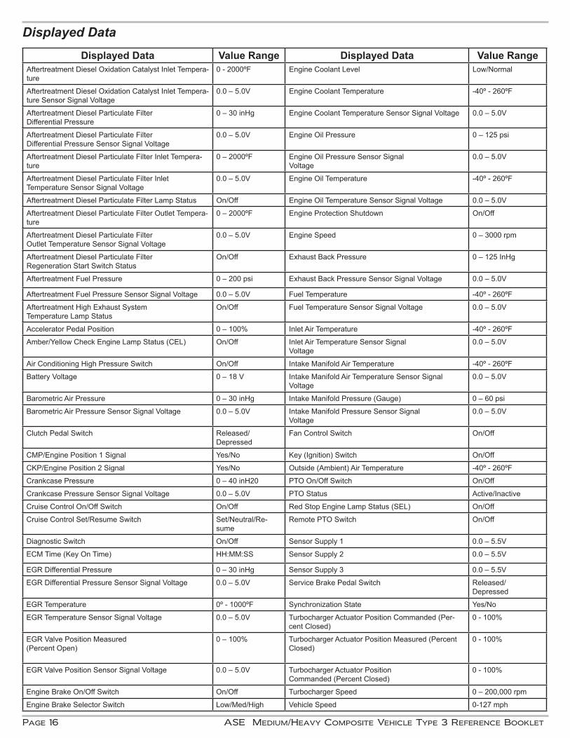
A breakout tool can be connected into a circuit to measure voltage signals and resistance values with a digital multimeter (DMM). A diagnostic tool can be connected to the data link connector to read en-gine data, diagnostic codes, and set programmable parameters. ECM software updates (re-flash) can be performed using a PC based diagnostic tool. The Displayed Data chart shows how diagnostic tool data will be presented in some Composite Vehicle test questions. The chart includes how the status of components (switches and lamps) or opera-tional modes will be indicated. The minimum – maximum measurement range and values for engine data (voltages, temperatures, pressures, and speeds) is also shown.
(Please refer to the chart that follows.)
Page 16 ASE Medium/Heavy Composite Vehicle Type 3 Reference Booklet
Displayed Data Value Range Displayed Data Value RangeAftertreatment Diesel Oxidation Catalyst Inlet Tempera-ture
0 - 2000ºF Engine Coolant Level Low/Normal
Aftertreatment Diesel Oxidation Catalyst Inlet Tempera-ture Sensor Signal Voltage
0.0 – 5.0V Engine Coolant Temperature -40º - 260ºF
Aftertreatment Diesel Particulate Filter Differential Pressure
0 – 30 inHg Engine Coolant Temperature Sensor Signal Voltage 0.0 – 5.0V
Aftertreatment Diesel Particulate Filter Differential Pressure Sensor Signal Voltage
0.0 – 5.0V Engine Oil Pressure 0 – 125 psi
Aftertreatment Diesel Particulate Filter Inlet Tempera-ture
0 – 2000ºF Engine Oil Pressure Sensor Signal Voltage
0.0 – 5.0V
Aftertreatment Diesel Particulate Filter Inlet Temperature Sensor Signal Voltage
0.0 – 5.0V Engine Oil Temperature -40º - 260ºF
Aftertreatment Diesel Particulate Filter Lamp Status On/Off Engine Oil Temperature Sensor Signal Voltage 0.0 – 5.0V
Aftertreatment Diesel Particulate Filter Outlet Tempera-ture
0 – 2000ºF Engine Protection Shutdown On/Off
Aftertreatment Diesel Particulate Filter Outlet Temperature Sensor Signal Voltage
0.0 – 5.0V Engine Speed 0 – 3000 rpm
Aftertreatment Diesel Particulate Filter Regeneration Start Switch Status
On/Off Exhaust Back Pressure 0 – 125 InHg
Aftertreatment Fuel Pressure 0 – 200 psi Exhaust Back Pressure Sensor Signal Voltage 0.0 – 5.0V
Aftertreatment Fuel Pressure Sensor Signal Voltage 0.0 – 5.0V Fuel Temperature -40º - 260ºF
Aftertreatment High Exhaust System Temperature Lamp Status
On/Off Fuel Temperature Sensor Signal Voltage 0.0 – 5.0V
Accelerator Pedal Position 0 – 100% Inlet Air Temperature -40º - 260ºF
Amber/Yellow Check Engine Lamp Status (CEL) On/Off Inlet Air Temperature Sensor Signal Voltage
0.0 – 5.0V
Air Conditioning High Pressure Switch On/Off Intake Manifold Air Temperature -40º - 260ºF
Battery Voltage 0 – 18 V Intake Manifold Air Temperature Sensor Signal Voltage
0.0 – 5.0V
Barometric Air Pressure 0 – 30 inHg Intake Manifold Pressure (Gauge) 0 – 60 psi
Barometric Air Pressure Sensor Signal Voltage 0.0 – 5.0V Intake Manifold Pressure Sensor Signal Voltage
0.0 – 5.0V
Clutch Pedal Switch Released/ Depressed
Fan Control Switch On/Off
CMP/Engine Position 1 Signal Yes/No Key (Ignition) Switch On/Off
CKP/Engine Position 2 Signal Yes/No Outside (Ambient) Air Temperature -40º - 260ºF
Crankcase Pressure 0 – 40 inH20 PTO On/Off Switch On/Off
Crankcase Pressure Sensor Signal Voltage 0.0 – 5.0V PTO Status Active/Inactive
Cruise Control On/Off Switch On/Off Red Stop Engine Lamp Status (SEL) On/Off
Cruise Control Set/Resume Switch Set/Neutral/Re-sume
Remote PTO Switch On/Off
Diagnostic Switch On/Off Sensor Supply 1 0.0 – 5.5V
ECM Time (Key On Time) HH:MM:SS Sensor Supply 2 0.0 – 5.5V
EGR Differential Pressure 0 – 30 inHg Sensor Supply 3 0.0 – 5.5V
EGR Differential Pressure Sensor Signal Voltage 0.0 – 5.0V Service Brake Pedal Switch Released/ Depressed
EGR Temperature 0º - 1000ºF Synchronization State Yes/No
EGR Temperature Sensor Signal Voltage 0.0 – 5.0V Turbocharger Actuator Position Commanded (Per-cent Closed)
0 - 100%
EGR Valve Position Measured(Percent Open)
0 – 100% Turbocharger Actuator Position Measured (Percent Closed)
0 - 100%
EGR Valve Position Sensor Signal Voltage 0.0 – 5.0V Turbocharger Actuator Position Commanded (Percent Closed)
0 - 100%
Engine Brake On/Off Switch On/Off Turbocharger Speed 0 – 200,000 rpm
Engine Brake Selector Switch Low/Med/High Vehicle Speed 0-127 mph
Displayed Data
ASE Medium/Heavy Composite Vehicle Type 3 Reference Booklet Page 17
Feature Range Setting Feature Range SettingRoad Speed Governor PTO/Remote PTO
Accelerator Max. Road Speed 30-120 mph 65 mph Max PTO Speed 600-2500 rpm 1000 rpm
Accelerator Upper Droop 0-3 mph 0 mph Min PTO Speed 600-2500 rpm 700 rpm
Accelerator Lower Droop 0-3 mph 1 mph Set PTO Speed 600-2500 rpm 900 rpm
Global Max. Road Speed 0-120 mph 120 mph Resume PTO Speed 600-2500 rpm 1000 rpm
Gear Down Protection (GDP) Remote PTO Speed 600-2500 rpm 1000 rpm
GDP Light Load Vehicle Speed 30-1000 mph 54 mph Max. Engine Load 0-1850 ft.lb. 800 ft.lb.
GDP Heavy Load Vehicle Speed 30-1000 mph 60 mph Max. Vehicle Speed 0-30 mph 0 mph
Idle Speed Control Ramp Rate 100-2500 rpm/sec 250 rpm/sec
Idle Engine Speed 600-850 rpm 700 rpm AftertreatmentIdle Shutdown Stationary Regeneration in PTO Enabled/Disabled Enabled
Idle Shutdown Timer 1-100 min. 5.0 min. Automatic Stationary Regeneration Enabled/Disabled Enabled
Idle Shutdown Lower Ambient Air Temp.
0-100ºF 40ºF Mobile/Active Regeneration Enabled/Disabled Enabled
Idle Shutdown Upper AmbientAir Temperature Override
0-100ºF 5.0 min. Automatic Stationary Regeneration Enabled/Disabled Enabled
Idle Shutdown Percent PTO Load Override
0-100% 100% Diesel Particulate Filter Lamp Enabled/Disabled Enabled
Idle Shutdown Enabled/Disabled Enabled Diesel Particulate FilterRegeneration Permit Switch
Enabled/Disabled Enabled
Idle Shutdown Manual Override Enabled/Disabled Enabled Diesel Particulate FilterRegeneration Start Switch
Enabled/Disabled Enabled
Fan Control High Exhaust System TemperatureLamp
Enabled/Disabled Enabled
Minimum Fan On Time 0-1000 sec. 240 sec. Vehicle Setup Parameters
Fan Control Solenoid Logic 0 Volts ON Rear Axle Ratio 2-15.98 4.1
Fan On During Engine Braking Enabled/Disabled Enabled Tire Size 301-700 rev/mile 501
Fan Vehicle Speed Interaction Enabled/Disabled Enabled No. of Tailshaft Gear Teeth 1-64 16
Fan Control A/C Press Switch Enabled/Disabled Enabled Vehicle Speed Sensor Type Magnetic
Fan Control Switch Enabled/Disabled Enabled Max. Engine Speed w/out VSS 1400-3000 rpm 1800 rpm
Cruise Control/Engine Brakes Max. Engine Speed with VSS 1400-3000 rpm 2100 rpm
Max. Cruise Control Speed 30-102 mph 65 mph Trans. Top Gear Ratio 0.1-2 1.00
Cruise Control Upper Droop 0-3 mph 0 mph Trans. One Gear Down Ratio 0.1-16 1.34
Cruise Control Lower Droop 0-3 mph 2 mph Transmission Type Manual
Cruise Control Speed Delta for Max. Engine Brake
0-6 mph 5 mph Multiplexing Ambient Air Temperature Sensor
J1939
Cruise Control Speed Delta for Min. Engine Brake
0-102 mph 3 mph Ambient Air Temperature Source Address
0-255 51
Cruise Control Feature Enabled/Disabled Enabled Multiplexing Parking Brake Switch J1939
Engine BrakeCruise Control Activation
Enabled/Disabled Enabled Parking Brake Source Address 0-255 49
Engine Brake Min. Vehicle Speed 0-35 mph 0 mph Engine Protection
Engine Brake Delay 0-10 sec. 0 sec. Engine ProtectionShutdown Feature
Warning/Derate/Shutdown
Shutdown
Engine Brake Service Brake Activation
Enabled/Disabled Enabled Engine Protect Restart Inhibit Enabled/Disabled Enabled
Engine Brake Control Enabled/Disabled Enabled Manual Override Enabled/Disabled Enabled
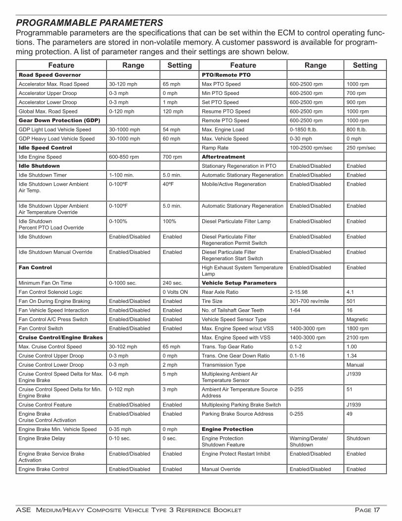
PROGRAMMABLE PARAMETERSProgrammable parameters are the specifications that can be set within the ECM to control operating func-tions. The parameters are stored in non-volatile memory. A customer password is available for program-ming protection. A list of parameter ranges and their settings are shown below.
Page 18 ASE Medium/Heavy Composite Vehicle Type 3 Reference Booklet
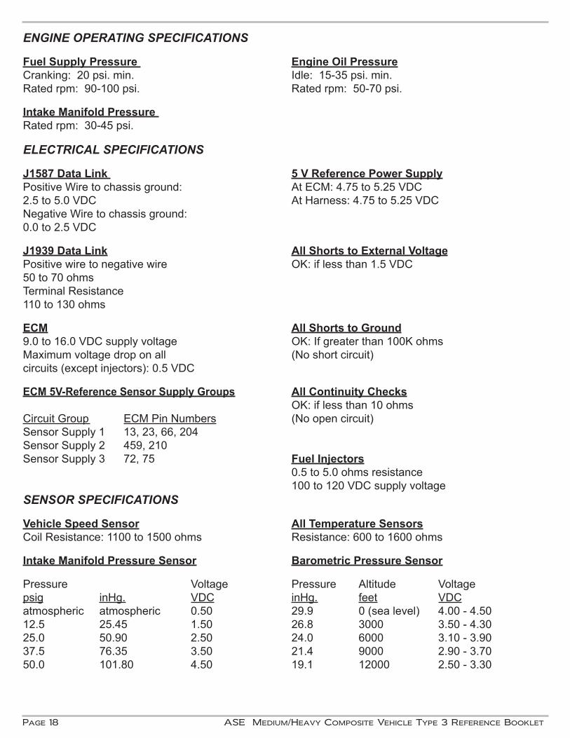
ENGINE OPERATING SPECIFICATIONS
Fuel Supply Pressure Engine Oil PressureCranking: 20 psi. min. Idle: 15-35 psi. min.Rated rpm: 90-100 psi. Rated rpm: 50-70 psi. Intake Manifold Pressure Rated rpm: 30-45 psi.
ELECTRICAL SPECIFICATIONS
J1587 Data Link 5 V Reference Power SupplyPositive Wire to chassis ground: At ECM: 4.75 to 5.25 VDC 2.5 to 5.0 VDC At Harness: 4.75 to 5.25 VDCNegative Wire to chassis ground:0.0 to 2.5 VDC
J1939 Data Link All Shorts to External VoltagePositive wire to negative wire OK: if less than 1.5 VDC50 to 70 ohmsTerminal Resistance110 to 130 ohms
ECM All Shorts to Ground9.0 to 16.0 VDC supply voltage OK: If greater than 100K ohmsMaximum voltage drop on all (No short circuit)circuits (except injectors): 0.5 VDC
ECM 5V-Reference Sensor Supply Groups All Continuity Checks OK: if less than 10 ohmsCircuit Group ECM Pin Numbers (No open circuit)Sensor Supply 1 13, 23, 66, 204Sensor Supply 2 459, 210Sensor Supply 3 72, 75 Fuel Injectors 0.5 to 5.0 ohms resistance 100 to 120 VDC supply voltageSENSOR SPECIFICATIONS Vehicle Speed Sensor All Temperature SensorsCoil Resistance: 1100 to 1500 ohms Resistance: 600 to 1600 ohms
Intake Manifold Pressure Sensor Barometric Pressure Sensor
Pressure Voltage Pressure Altitude Voltagepsig inHg. VDC inHg. feet VDCatmospheric atmospheric 0.50 29.9 0 (sea level) 4.00 - 4.5012.5 25.45 1.50 26.8 3000 3.50 - 4.3025.0 50.90 2.50 24.0 6000 3.10 - 3.9037.5 76.35 3.50 21.4 9000 2.90 - 3.7050.0 101.80 4.50 19.1 12000 2.50 - 3.30
ASE Medium/Heavy Composite Vehicle Type 3 Reference Booklet Page 19
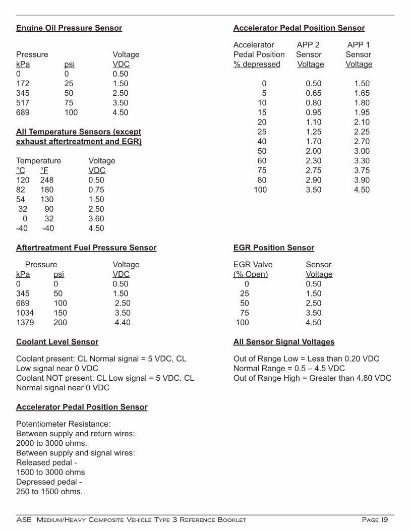
Engine Oil Pressure Sensor Accelerator Pedal Position Sensor
Accelerator APP 2 APP 1Pressure Voltage Pedal Position Sensor SensorkPa psi VDC % depressed Voltage Voltage0 0 0.50172 25 1.50 0 0.50 1.50345 50 2.50 5 0.65 1.65517 75 3.50 10 0.80 1.80689 100 4.50 15 0.95 1.95 20 1.10 2.10All Temperature Sensors (except 25 1.25 2.25exhaust aftertreatment and EGR) 40 1.70 2.70 50 2.00 3.00Temperature Voltage 60 2.30 3.30°C °F VDC 75 2.75 3.75120 248 0.50 80 2.90 3.9082 180 0.75 100 3.50 4.5054 130 1.50 32 90 2.50 0 32 3.60-40 -40 4.50 Aftertreatment Fuel Pressure Sensor EGR Position Sensor
Pressure Voltage EGR Valve Sensor kPa psi VDC (% Open) Voltage0 0 0.50 0 0.50345 50 1.50 25 1.50689 100 2.50 50 2.501034 150 3.50 75 3.501379 200 4.40 100 4.50
Coolant Level Sensor All Sensor Signal Voltages
Coolant present: CL Normal signal = 5 VDC, CL Out of Range Low = Less than 0.20 VDCLow signal near 0 VDC Normal Range = 0.5 – 4.5 VDCCoolant NOT present: CL Low signal = 5 VDC, CL Out of Range High = Greater than 4.80 VDC Normal signal near 0 VDC
Accelerator Pedal Position Sensor
Potentiometer Resistance:Between supply and return wires: 2000 to 3000 ohms.Between supply and signal wires:Released pedal - 1500 to 3000 ohmsDepressed pedal - 250 to 1500 ohms.

©1998-2017 by the National Institute for AUTOMOTIVE SERVICE EXCELLENCE (ASE)All rights reserved
101 Blue Seal Dr. S.E., Suite 101, Leesburg, VA 20175 • (703) 669-6600 • www.ase.com
Prometric Inventory Code:
P6943