Embed Size (px)
Citation preview

Readers are advised to check the validity of this Certificate by either referring to the BBA’s website (www.bbacerts.co.uk) or contactingthe BBA direct (Telephone Hotline 01923 665400).
1 The Building Regulations 2000 (as amended) (England and Wales)The Secretary of State has agreed with the British Board of Agrémentthe aspects of performance to be used by the BBA in assessing thecompliance of drainage systems with the Building Regulations. In the
opinion of the BBA, the Vulcathene Mechanical and Enfusion LaboratoryDrainage System, if used in accordance with the provisions of this Certificate,will meet or contribute to meeting the relevant requirements.Requirement: B3(4) Internal fire spread (structure)
Comment: Any pipe passing through a separating wall, compartmentfloor or compartment wall should be protected to meet theprovisions in Appendix F. See section 5 of these Front Sheets.
Requirement: H1(1) Foul water drainage
Comment: See the marked sections in the Design Data parts of theaccompanying Detail Sheets.
Requirement: H3(1) Rainwater drainage
Comment: See the marked sections in the Design Data parts of theaccompanying Detail Sheets.
Requirement: Regulation 7 Materials and workmanship
Comment: The system is acceptable.
VulcatheneWalsall RoadNorton CanesCannockStaffordshire WS11 3NSTel: 01543 279909 Fax: 01543 279450e-mail: [email protected]: www.durapipe.co.uk
AgrémentCertificate
No 92/2805Fourth issue*
Designated by Governmentto issue
European TechnicalApprovals
VULCATHENE MECHANICAL AND ENFUSIONLABORATORY DRAINAGE SYSTEMSystèmes de canalisations d’évacuationAbflußleitungen
Product
Regulations — Detail Sheet 1• THIS CERTIFICATE RELATESTO THE VULCATHENEMECHANICAL ANDENFUSION LABORATORYDRAINAGE SYSTEM, ANABOVE-GROUND DRAINAGESYSTEM, THE COMPONENTSOF WHICH ARE REFERRED TOIN THE ACCOMPANYINGDETAIL SHEETS.• The system is for use forlaboratory drainage systemswhere the chemical resistanceof the polypropylene is suitablefor the envisaged effluent.CP 312-1 : 1973 givesguidance on the chemicalresistance of polypropylenepipework both at normal andelevated temperatures. Theadvice of the manufacturer
CI/SfB
(52) In6
continued
Electronic CopyElectronic Copy
2
2 The Building Standards (Scotland) Regulations 1990 (as amended)In the opinion of the BBA, the Vulcathene Mechanical and EnfusionLaboratory Drainage System, if used in accordance with the provisionsof this Certificate, will satisfy or contribute to satisfying the various
Regulations and related Technical Standards as listed below.Regulation: 10 Fitness of materials and workmanshipStandard: B2.1 Selection and use of materials, fittings, and components, and workmanship
Comment: The product can contribute to a construction meeting thisStandard. See the Installation part of this Certificate.
Standard: B2.2 Selection and use of materials, fittings, and components, and workmanship
Comment: The product is an acceptable material. See the markedsections in Durability of the accompanying Detail Sheets.
Regulation: 12 Structural fire precautionsStandard: D6.7 Concealed spaces — Openings
Comment: A pipe which passes through a separating wall or separatingfloor or a compartment wall or compartment floor must beconstructed, or protected, so that in the event of fire the fireresistance required for the wall or floor is maintained. Everyservice opening through an element must be suitably fire-stopped. See section 5 of these Front Sheets.
3 The Building Regulations (Northern Ireland) 2000In the opinion of the BBA, the Vulcathene Mechanical and EnfusionLaboratory Drainage System, if used in accordance with the provisionsof this Certificate, will satisfy or contribute to satisfying the various
Building Regulations as listed below.Regulation: B2 Fitness of materials and workmanship
Comment: The system is acceptable.Regulation: E3 Internal fire spread — Linings
Comment: Any pipe which passes through a separating wall orprotecting structure should be protected. See section 5 ofthese Front Sheets.
Regulation: N3 Sanitary pipework
Comment: The system will meet the requirements of this Regulation. Seethe marked sections in the Design Data of the accompanyingDetail Sheets.
continued
4 Construction (Design and Management) Regulations 1994 (as amended)Construction (Design and Management) Regulations (Northern Ireland)1995 (as amended)
Information in this Certificate may assist the client, planning supervisor,designer and contractors to address their obligations under these Regulations.See sections: 2 Delivery and site handling (2.2) of Detail Sheets 2, 3 and 4
and (2) of Detail Sheet 5, 11 General of Detail Sheets 2 and4 (11.1 and 11.2), 13 General of Detail Sheet 3,14 General of Detail Sheet 5 and Installation and12 Procedure (12.12, 12.17, 12.18, 12.20 and 12.21)of Detail Sheet 2, 15 Procedure (15.1, 15.2 and 15.4) ofDetail Sheet 5.
should be sought for resistanceto chemicals not covered byCP 312-1 : 1973.• The system is for use indomestic, commercial andpublic buildings in accordancewith BS EN 12056-2 : 2000for the conveyance of chemicalwaste and domestic drainageand sewage as is permitted tobe discharged into publicsewers by the Water IndustryAct, Chapter 56 1991 andsewage as is permitted anddefined by the Sewerage(Scotland) Act 1968 and theWater and Sewerage Services(Northern Ireland) Order1973.
These Front Sheets must be readin conjunction with theaccompanying Detail Sheets,which relate to specificcomponents of the system andprovide information on their useeither individually or incombination.
Design Data
5 Properties in relation to fireThe regulations concerning the prevention offire spread by fire-stopping (listed in DetailSheet 1) must be taken into account if the
drainage system passes through a fire rated wall orfloor.
Additional Information
The Durapipe UK quality management system isregistered by BSI to ISO 9001 : 1994.
Bibliography
BS EN 12056-2 : 2000 Gravity DrainageSystems inside Buildings — Sanitary pipework,layout and calculation
ISO 9001 : 1994 Quality managementsystems — Requirements
CP 312-1 : 1973 Code of practice for plasticspipework (thermoplastics material) — Generalprinciples and choice of material
Electronic CopyElectronic Copy
Conditions of Certification
6 Conditions6.1 This Certificate:(a) relates only to the product that is described,installed, used and maintained as set out in thisCertificate;(b) is granted only to the company, firm or personidentified on the front cover — no other company,firm or person may hold or claim any entitlement tothis Certificate;(c) has to be read, considered and used as awhole document — it may be misleading and willbe incomplete to be selective;(d) is copyright of the BBA.
6.2 References in this Certificate to any Act ofParliament, Regulation made thereunder, Directiveor Regulation of the European Union, StatutoryInstrument, Code of Practice, British Standard,manufacturers’ instructions or similar publication,shall be construed as references to such publicationin the form in which it was current at the date ofthis Certificate.
6.3 This Certificate will remain valid for anunlimited period provided that the product and themanufacture and/or fabricating process(es) thereof:(a) are maintained at or above the levels whichhave been assessed and found to be satisfactoryby the BBA;
(b) continue to be checked by the BBA or itsagents; and(c) are reviewed by the BBA as and when itconsiders appropriate.
6.4 In granting this Certificate, the BBA makes norepresentation as to:(a) the presence or absence of any patent orsimilar rights subsisting in the product or any otherproduct;(b) the right of the Certificate holder to market,supply, install or maintain the product; and(c) the nature of individual installations of theproduct, including methods and workmanship.
6.5 Any recommendations relating to the use orinstallation of this product which are contained orreferred to in this Certificate are the minimumstandards required to be met when the product isused. They do not purport in any way to restate therequirements of the Health & Safety at Work etcAct 1974, or of any other statutory, common lawor other duty which may exist at the date of thisCertificate or in the future; nor is conformity withsuch recommendations to be taken as satisfying therequirements of the 1974 Act or of any present orfuture statutory, common law or other duty of care.In granting this Certificate, the BBA does notaccept responsibility to any person or body for anyloss or damage, including personal injury, arisingas a direct or indirect result of the installation anduse of this product.
3
In the opinion of the British Board of Agrément, the Vulcathene Mechanical and EnfusionLaboratory Drainage System is fit for its intended use provided it is installed, used and maintainedas set out in this Certificate. Certificate No 92/2805 is accordingly awarded to Vulcathene.
On behalf of the British Board of Agrément
Date of Fourth issue: 24th September 2003 Chief Executive
*Original Certificate was issued to Vulcathene (Glynwed Plastics Ltd) on 6th November 1992. This amended versionincludes the addition of the Enfusion system and reference to revised Building Regulations.
Electronic CopyElectronic Copy

British Board of AgrémentP O Box No 195, Bucknalls LaneGarston, Watford, Herts WD25 9BAFax: 01923 665301
©2003For technical or additional information,contact the Certificate holder (seefront page).For information about the AgrémentCertificate, including validity andscope, tel: Hotline 01923 665400,or check the BBA website.
e-mail: [email protected]: www.bbacerts.co.uk
Electronic CopyElectronic Copy
Readers are advised to check the validity of this Detail Sheet by either referring to the BBA’s website (www.bbacerts.co.uk) or contactingthe BBA direct (Telephone Hotline 01923 665400).
Technical Specification
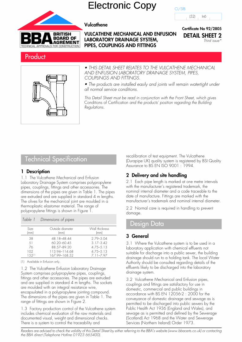
1 Description1.1 The Vulcathene Mechanical and EnfusionLaboratory Drainage System comprises polypropylenepipes, couplings, fittings and other accessories. Thedimensions of the pipes are given in Table 1. The pipesare extruded and are supplied in standard 4 m lengths.The olives for the mechanical joint are moulded in athermoplastic elastomer material. The range ofpolypropylene fittings is shown in Figure 1.
Table 1 Dimensions of pipes
Size Outside diameter Wall thickness(mm) (mm) (mm)
38 48.18–48.44 2.79–3.0451 60.20–60.45 3.17–3.4276 88.57–89.20 4.75–5.13
102 113.94–114.68 4.75–5.13152(1) 167.99–168.52 7.11–7.97
(1) Available in Enfusion only.
1.2 The Vulcathene Enfusion Laboratory DrainageSystem comprises polypropylene pipes, couplings,fittings and other accessories. The pipes are extrudedand are supplied in standard 4 m lengths. The socketsare moulded with an integral resistance wire,encapsulated in a polypropylene jointing compound.The dimensions of the pipes are given in Table 1. Therange of fittings are shown in Figure 2.
1.3 Factory production control of the Vulcathene systemincludes chemical evaluation of the raw materials anddocumented visual, weight and dimensional checks.There is a system to control the traceability and
recalibration of test equipment. The Vulcathene(Durapipe UK) quality system is registered by BSI QualityAssurance to BS EN ISO 9001 : 1994.
2 Delivery and site handling2.1 Each pipe length is marked at one metre intervalswith the manufacturer’s registered trademark, thenominal internal diameter and a code traceable to thedate of manufacture. Fittings are marked with themanufacturer’s trademark and nominal internal diameter.
2.2 Normal care is required in handling to preventdamage.
Design Data
3 General3.1 Where the Vulcathene system is to be used in alaboratory application with chemical effluents notsuitable for discharge into a public sewer, the buildingdrainage should run to a holding tank. The local WaterAuthority should be consulted regarding details of theeffluents likely to be discharged into the laboratorydrainage system.
3.2 Vulcathene Mechanical and Enfusion pipes,couplings and fittings are satisfactory for use indomestic, commercial and public buildings inaccordance with BS EN 12056-2 : 2000 for theconveyance of domestic drainage and sewage as ispermitted to be discharged into public sewers by thePublic Health Act 1936 (England and Wales), andsewage as is permitted and defined by the Sewerage(Scotland) Act 1968 and the Water and SewerageServices (Northern Ireland) Order 1973.
• THIS DETAIL SHEET RELATES TO THE VULCATHENE MECHANICALAND ENFUSION LABORATORY DRAINAGE SYSTEM, PIPES,COUPLINGS AND FITTINGS.• The products are installed easily and joints will remain watertight underall normal service conditions.
This Detail Sheet must be read in conjunction with the Front Sheet, which givesConditions of Certification and the products' position regarding the BuildingRegulations.
Certificate No 92/2805
DETAIL SHEET 2Third issue*
Vulcathene
VULCATHENE MECHANICAL AND ENFUSIONLABORATORY DRAINAGE SYSTEM,PIPES, COUPLINGS AND FITTINGS
Product
CI/SfB
(52) In6
Electronic CopyElectronic Copy
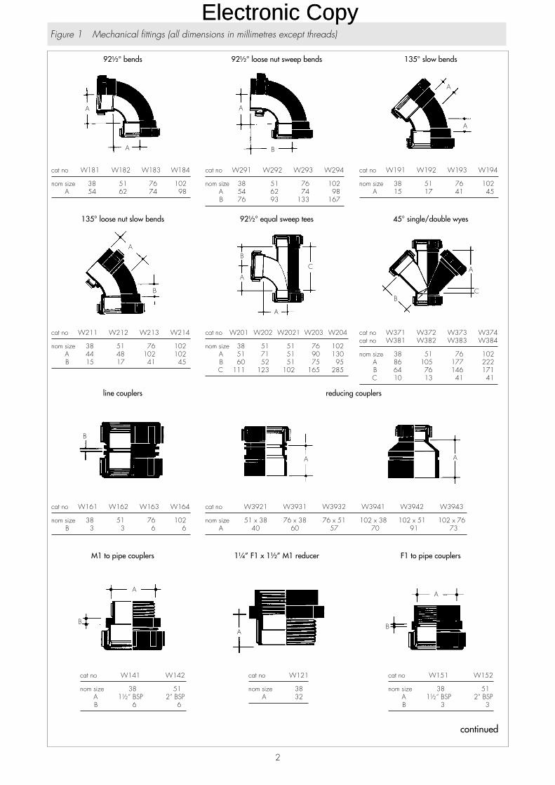
cat no W151 W152
nom size 38 51A 1½“ BSP 2” BSPB 3 3
cat no W121
nom size 38A 32
cat no W141 W142
nom size 38 51A 1½“ BSP 2” BSPB 6 6
F1 to pipe couplers1¼” F1 x 1½” M1 reducerM1 to pipe couplers
cat no W3921 W3931 W3932 W3941 W3942 W3943
nom size 51 x 38 76 x 38 76 x 51 102 x 38 102 x 51 102 x 76A 40 60 57 70 91 73
cat no W161 W162 W163 W164
nom size 38 51 76 102B 3 3 6 6
reducing couplersline couplers
cat no W371 W372 W373 W374cat no W381 W382 W383 W384
nom size 38 51 76 102A 86 105 177 222B 64 76 146 171C 10 13 41 41
cat no W201 W202 W2021 W203 W204
nom size 38 51 51 76 102A 51 71 51 90 130B 60 52 51 75 95C 111 123 102 165 285
cat no W211 W212 W213 W214
nom size 38 51 76 102A 44 48 102 102B 15 17 41 45
45° single/double wyes92½° equal sweep tees135° loose nut slow bends
cat no W191 W192 W193 W194
nom size 38 51 76 102A 15 17 41 45
cat no W291 W292 W293 W294
nom size 38 51 76 102A 54 62 74 98B 76 93 133 167
cat no W181 W182 W183 W184
nom size 38 51 76 102A 54 62 74 98
135° slow bends92½° loose nut sweep bends92½° bends
2
Figure 1 Mechanical fittings (all dimensions in millimetres except threads)
continuedcontinued
continued
Electronic CopyElectronic Copy

cat no W801 W802 W803 / W804
nom size 38 51 76 102A min 70 149 9 9A max 108 203 60 60
thermal stress relief units
Table ‘D’
cat no W101 T.D. W102 T.D. W103 T.D. W104 T.D.
nom size 38 51 76 102A 30 30 41 41B 133 152 187 216C 16 16 19 19
‘Vulcathene’ Table
cat no W101 V.T. W102 V.T. W103 V.T. W104 V.T.
nom size 38 51 76 102A 25 26 33 33B 92 111 152 178C 16 16 19 19D 6 6 6 6
flanges
cat no 91101 91201 91301 91401
nom size 38 51 76 102A 38 44 67 89B 60 76 111 140C 19 19 32 32
cat no W231 W232 W233 W234
nom size 38 51 76 102A 67 83 134 162B 21 25 33 35
cat no W271
nom size 38A 1¾“ BSPB 5
pipe clipsnuts1¾” F1 to pipe coupler
3
Figure 1 Mechanical fittings (continued)
Electronic CopyElectronic Copy

cat no L341 L342
nom size 38 51A 56 64B 23 25
cat no L3721 L3731 L3732 L3742 L3743
nom size 51 x 51 76 x 76 76 x 76 102 x 102 102 x 102x 38 x 38 x 51 x 51 x 76
A 84 144 144 165 211B 27 22 22 10 41C 87 178 146 165 235
cat no L3762 L3763 L3764
nom size 152 x 152 152 x 152 152 x 152x 51 x 76 x 102
A 184 184 184B 10 10 10C 242 248 196
cat no L371 L372 L373 L374 L376
nom size 38 51 76 102 152A 83 92 168 212 241B 29 36 38 46 44C 83 92 168 187 241
A A
BC
A
BC B
A
double wye45° reducing wye45° single wye
cat no L2021 L2031 L2032 L2042 L2043
nom size 51 x 51 76 x 76 76 x 76 102 x 102 102 x 102x 38 x 38 x 51 x 51 x 76
A 57 114 83 117 89B 70 90 89 95 64C 51 65 66 39 235D 120 155 155 133 142
cat no L201 L202 L203 L204
nom size 38 51 76 102A 57 57 79 98B 70 70 102 84C 51 51 66 106D 121 121 168 190
cat no L211 L212 L213 L214 L216
nom size 38 51 76 102 152A 28 38 51 51 43B 38 76 95 100 114
C
B
A
DC
B
A
D
A
B
92½° reducing sweep tee92½° equal sweep tee45° single socket slow bend
cat no L191 L192 L193 L194 L196
nom size 38 51 76 102 152A 28 38 51 51 43
cat no L181 L182
nom size 38 51A 43 64
cat no L171 L172 L173 L174 L176
nom size 38 51 76 102 152A 89 102 130 155 198
A
A
A
AA
45° double socket slow benddouble socket short sweep benddouble socket long sweep bend
cat no L291A
nom size 38A 87B 114
cat no L291 L292
nom size 38 51A 43 57B 75 94
cat no L281 L282 L283 L284 L286
nom size 38 51 76 102 152A 89 102 128 155 197B 117 136 171 203 247
B
A
B
A
B
A
loose nut/socket short sweep bendsingle socket short sweep bendsingle socket long sweep bend
4
Figure 2 Enfusion fittings (all dimensions in millimetres except threads)
continued
Electronic CopyElectronic Copy

pipe scraperlink cableclamps
A
A
E
CBA D
enfusion control unitcleanout plugflange
cat no L803 L804 L806
nom size 76 102 152A min 9 9 9A max 60 60 60
cat no L802
nom size 51A min 149A max 203
cat no L801
nom size 38A max 70A min 108
A
AA
thermal stress relief units
cat no L151 L152
nom size 38 51A 8 8
cat no L141 L142
nom size 38 51A 6 6
cat no L3912 L3913 L3923 L3914 L3924
nom size 51 x 38 76 x 38 76 x 51 102 x 38 102 x 51A 32 52 42 51 51
cat no L3912 L3913 L3923 L3914 L3924
nom size 102 x 76 152 x 38 152 x 51 152 x 76 152 x 102A 47 65 64 64 64
AAA
F1 to pipe couplerM1 to pipe couplerreducing coupler
cat no L161 L162 L163 L164 L165
nom size 38 51 76 102 152A 6 8 11 11 13
cat no L351 L352 L353 L354
nom size 38 51 76 102A 59 71 86 98B 90 105 79 84C 42 48 54 88D 132 153 133 172
cat no L3421 L3432 L3443
nom size 51 x 38 76 x 51 102 x 76A 61 61 77B 18 13 25
A
C
B
A
D
A A
B
coupling92½° double branchreducing double wye
5
Figure 2 Enfusion fittings (continued)
Electronic CopyElectronic Copy
4 Strength4.1 Vulcathene Mechanical and Enfusion pipes,couplings and fittings will have adequate resistanceto the forms of loading associated with installation.
4.2 The products should be protected from impacts, forexample, from heavy vehicles such as fork-lift trucks usedon commercial premises.
5 Performance of joints5.1 The joints will not be adversely affected by thermalmovement when correctly made.
5.2 The joints will remain watertight under conditions ofpipeline movement in excess of those expected to occurin normal good drainage practice.
6 Flow characteristics6.1 A drainage system comprising VulcatheneMechanical and Enfusion pipes, couplings andfittings will have satisfactory flow characteristics.
Non-swept branch connections are restricted inaccordance with BS EN 12056-2 : 2000.
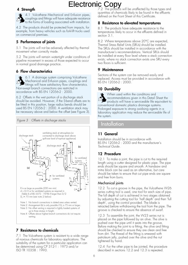
6.2 Offsets in the wet portion of a discharge stackshould be avoided. However, if the S-bend offsets are tobe fitted in this position, large radius bends should beused BS EN 12056-2 : 2000. A ventilation stack maybe necessary above and below the offset (see Figure 3).
Figure 3 Offsets in discharge stacks
7 Resistance to chemicals7.1 The Vulcathene system is resistant to a wide rangeof noxious chemicals for laboratory applications. Thesuitability of the system for a particular application canbe determined using CP 312-1 : 1973 and/orISO TR 10358 : 1993.
7.2 The products will be unaffected by those types andquantities of chemicals likely to be found in the effluentsdefined on the Front Sheet of this Certificate.
8 Resistance to elevated temperatures8.1 The products have adequate resistance to thetemperatures likely to occur in the effluents defined insection 3.1.
8.2 Where temperatures above 20°C are expected,Thermal Stress Relief Units (SRUs) should be installed.The SRUs should be installed in accordance with themanufacturer’s recommendations. Vertical SRUs shouldbe installed at every floor level where a stack connectionexists; where no stack connection exists one SRU everytwo floors is sufficient.
9 MaintenanceSections of the system can be removed easily andreplaced. Access must be provided in accordance withBS EN 12056-2 : 2000.
10 DurabilityWhen used within the conditions andrecommendations given in this Detail Sheet theproducts will have a serviceable life equivalent to
conventional domestic plastics drainage systems.Prolonged exposure to strong oxidising agents in alaboratory application may reduce the serviceable life ofthe system.
Installation
11 GeneralInstallation should be in accordance withBS EN 12056-2 : 2000 and the manufacturer’sTechnical Guide.
12 Procedure12.1 To make a joint, the pipe is cut to the requiredlength using a cutter designed for plastic pipe. The pipeends should be square and smooth. A handsaw andmitre block can be used as an alternative, but careshould be taken to ensure that cut pipe ends are squareand free from burrs.
Mechanical joints12.2 To cut a groove in the pipe, the Vulcathene W26series cutting tool is used, one tool for each size of pipe.The full depth of cut is achieved in two stages obtainedby adjusting the cutting tool for ‘half depth’ and then ‘fulldepth’, using the control provided. The blade isretracted before withdrawing the tool from the pipe. Thegroove is checked to ensure the absence of swarf.
12.3 To assemble the joint, the W23 series nut isplaced on the pipe followed by an olive. The olive ispushed over the pipe until it seats into the groove.Before making the joint to a fitting, the olive and fittingshould be checked to ensure they are clean and freefrom dirt. The thread of the fitting is smeared withpetroleum jelly, pushed over the olive and the nuttightened by hand.
12.4 For the other pipe to be jointed, the proceduredescribed in sections 12.2 and 12.3 is repeated.
R is as large as possible (200 mm min)d = D/2 or for ventilated systems as required in(Table 6 of BS 5572 : 1978) if larger than D/2
D 75 mm (see note 2 below)
Note 1 No branch connections in dotted area unless vented.Note 2 Arrangement (b) is only possible if D is 75 mm or larger.Note 3 No offset venting is required in lightly loaded systems of
up to three storeys in height.Note 4 Offsets above highest branch connections do not require
venting.
b
b
�
ventilating stack at atmosphere (orconnected to discharge stack abovespill-over level of topmost appliance)
discharge stack
d
discharge stack
(b)
for ventilatedsystems
D
for ventilatedsystems
(a) R
R
d
d
Db
R
R
Db
D
6
Electronic CopyElectronic Copy

12.5 The W23 series nuts are tightened using theVulcathene W36 series spanners.
12.6 It is important that the nuts are tightened as theinstallation progresses and not left until the job iscomplete.
Enfusion joints12.7 A pipe scraper is used to scrape the end of thepipe equivalent to the depth of the socket plus 50%.Removal of the slick or ‘skin’ on the surface of the pipe isimperative in order to obtain a good fusion joint. Onceprepared, this area must not be handled or allowed toget dirty.
12.8 The pipe is inserted all the way to the stop at thebottom of the socket.
12.9 It should be decided whether the joint is to bewelded singly or in series. See Table 2 if multiple jointsare to be made which indicates the maximum number ofjoints relative to the pipe size.
12.10 The appropriate-sized clamp(s) should beloosely fitted over the hub(s) of the socket(s) to be joinedand positioned flush with the socket opening.
12.11 The clamp(s) should be tightened round thehub(s) of the socket(s). It is important that the clamp(s)is/are fully tightened to obtain a homogeneous joint.
12.12 Before using the Enfusion Control Unit all cablesmust be unwound from the protective frame.
12.13 When Enfusion Control Unit is turned on it willself test and should display a copyright message.
12.14 Instruction on the display to ‘connect outputlead’ should be followed. If fusing a single joint, theoutput leads should be connected to one joint or ifmultiple joints, the link leads should be utilised asrequired.
12.15 Instructions are then displayed to ‘select pipesize’. When the correct size is displayed the start buttonis pressed and the Enfusion Control Unit displays thetemperature and the welding time.
12.16 When completed, the Enfusion Control Unitemits an audible alarm and displays the message‘disconnect output lead’. During this period the EnfusionControl Unit counts down to zero.
12.17 The joints should be allowed to cool(30 seconds), before gently disconnecting the leadsfrom the joints.
12.18 The joint should be left undisturbed for at leastfive minutes before the clamp(s) are removed.
Making multiple Enfusion joints12.19 Table 2 indicates the number of joints whichcan be fused at any one time utilising additional linkcables in series, as shown in Figure 4. The chart onlyapplies to joints of the same size. The use of the multiplejointing method for connecting joints of differing sizesshould not be attempted.
Table 2 Multiple joint fusion chart
Pipe size 38 mm 51 mm 76 mm 102 mm 152 mm
Maximum numberof joints 10 8 4 3 2
Figure 4 Typical multiple jointing configuration
Supporting pipes12.20 Pipe clip fixing centres are detailed in Table 3.
Table 3 Pipe clip fixing centres(1)
Horizontal installationNominal ID (mm) 38 51 76 102 152Fixing centres (cm) 122 137 152 183 183
Vertical installation1.5 m fixing centres for all pipe sizes
(1) It is recommended that where high sustained temperatures of effluentare expected, horizontal pipe runs are continuously supported usingVulcathene galvanized support channels.
Waste pipe falls12.21 Waste pipe runs should be installed to providea natural fall of at least 2°.
Jointing to cast iron or stoneware12.22 The end of the polypropylene pipe to be jointedshould be scored. The socket is packed half full withrope and is then caulked with acid-resistant cement (orproprietary brand of sealing compound) until level withthe bead of the collar.
Technical Investigations
The following is a summary of the technicalinvestigations carried out on the Vulcathene Mechanicaland Enfusion Laboratory Drainage System, Pipes,Couplings and Fittings.
13 TestsTests were carried out to determine:• dimensional accuracy• impact resistance of pipes to BS 4991 : 1974• impact resistance of fittings to BS 2782-11 :
Method 1108A : 1989• resistance to elevated temperature cycling to
BS 5255 : 1989, Appendix A and toBS EN 1055 : 1996
• tensile test to BS 2782-3 : Methods 320A to 320F :1976
link cable connectorcable
EnfusionControl
Unit
7
Electronic CopyElectronic Copy
• watertightness to BS EN 1053 : 1996• airtightness to BS EN 1054 : 1996• ring stiffness to BS EN ISO 9969 : 1995• strength of pipe supports• practicability of installation.
14 Investigations14.1 An evaluation of data was made to assess:• heat reversion of pipe to BS 4991 : 1974,
Appendix C• stress relief behaviour of fittings to BS 5255 : 1989,
Appendix B• resistance to short-term hydrostatic pressure to
BS 4991 : 1974, Appendix D• resistance to long-term hydrostatic pressure to
BS 4991 : 1974, Appendix E• system design• resistance to chemicals• suitability of materials• effect of crossflow.
14.2 Factory production control was examined,including the methods adopted for quality control, anddetails were obtained of the quality and composition ofthe materials used.14.3 A survey was conducted of existing users of theVulcathene system to establish the performance in use.14.4 A site visit was conducted to establish the ease ofinstallation.
Bibliography
BS 2782-3 : Methods 320A to 320F : 1976 Methodsof testing plastics — Mechanical properties — Tensilestrength, elongation and elastic modulusBS 2782-11 : Method 1108A : 1989 Methods oftesting plastics — Thermoplastics pipes, fittings andvalves — True impact rate (TIR) boundaries of pipes
BS 4991 : 1974 Specification for propylene copolymerpressure pipe
BS 5255 : 1989 Specification for thermoplastics wastepipe and fittings
BS 5572 : 1978 Code of practice for sanitary pipework
BS EN 1053 : 1996 Plastics piping systems —Thermoplastics piping systems for non-pressureapplications — Test method for watertightness
BS EN 1054 : 1996 Plastics piping systems —Thermoplastics piping systems for soil and wastedischarge — Test method for airtightness of joints
BS EN 1055 : 1996 Methods of testing plastics —Thermoplastics pipes, fittings and valves — Plasticspiping systems — Thermoplastics piping systems for soiland waste discharge inside buildings — Test method forresistance to elevated temperature cycling
BS EN 12056-2 : 2000 Gravity Drainage Systemsinside Buildings — Sanitary pipework, layout andcalculation
BS EN ISO 9001 : 1994 Quality systems. Model forquality assurance in design, development, production,installation and servicing
BS EN ISO 9969 : 1995 Thermoplastics pipes —Determination of ring stiffness
ISO TR 10358 : 1993 Plastics pipes and fittings —Combined chemical-resistance classification table
CP 312-1 : 1973 Code of practice for plasticspipework (thermoplastics material) — General principlesand choice of material
On behalf of the British Board of Agrément
Date of Third issue: 24th September 2003 Chief Executive
*Original Detail Sheet issued on 6th November 1992. This amended version includes the addition of the Enfusion System.
British Board of AgrémentP O Box No 195, Bucknalls LaneGarston, Watford, Herts WD25 9BAFax: 01923 665301
©2003For technical or additional information,contact the Certificate holder (seefront page).For information about the AgrémentCertificate, including validity andscope, tel: Hotline 01923 665400,or check the BBA website.
e-mail: [email protected]: www.bbacerts.co.uk
Electronic CopyElectronic Copy

Readers are advised to check the validity of this Detail Sheet by either referring to the BBA’s website (www.bbacerts.co.uk) or contactingthe BBA direct (Telephone Hotline 01923 665400).
Technical Specification
1 Description1.1 The Vulcathene Mechanical LaboratoryDrainage System, Sinks, Troughs, Drip Cups andTraps comprises the fittings described in this DetailSheet used in conjunction with the Vulcathenepipes and fittings described in additional DetailSheets contained in this Certificate.
1.2 The range of sinks, troughs and drip cups isshown in Figure 1. The 601 and 602 series blackpolypropylene sinks, drip cups and accessories areinjection moulded. The 605 series troughs and the604 series sinks are vacuum formed frompolypropylene. The 603 series troughs arefabricated from polyethylene. Sinks, troughs anddrip cups are connected to the traps by the 504series wastes, which have an integral grating andare supplied with a removable plug. Waste sealsto the sink, trough or drip cup are supplied with anitrile rubber gasket. The wastes are also suitablefor connection to metal sinks to BS 1244-2 : 1988and pottery sinks to BS 1206 : 1974 notmanufactured by Vulcathene. The polypropylenestanding waste tubes, 508 series plugs and 509series overflow assemblies are designed for usewith the 504 series wastes.
1.3 The range of traps is shown in Figure 2. Thetraps are manufactured from polypropylene. Trapstypes 910G, W691 and W571 have a clear
base of heat-resistant borosilicate glass. Details ofthe traps depths of seal and liquid capacities aregiven in Table 1.
Table 1 Depth of seal and liquid capacity — traps
Vulcathene Depth of seal Liquid capacityreference (mm) (L)
W681 76 2.3
W691 76 2.3
W612 76 4.5
910G 76 4.5
1.4 Factory production control of the Vulcathenesystem includes chemical evaluation of the rawmaterials and documented visual, weight anddimensional checks. There is a system to control thetraceability and recalibration of test equipment. TheVulcathene (Glynwed Pipe Systems Ltd) qualitysystem is registered by BSI Quality Assurance toBS EN ISO 9001 : 1994.
2 Delivery and site handling2.1 The traps are marked with the manufacturer’sregistered trademark and the nominal internaldiameter of the inlet and outlet connections.
2.2 The Vulcathene sinks, troughs, drip cups andtraps are robust but normal care is required inhandling to prevent damage, with the exception ofthe traps types 910G, W691 and W571 whichhave a borosilicate glass base and should behandled more carefully.
• THIS DETAIL SHEET RELATES TO THE VULCATHENE MECHANICALLABORATORY DRAINAGE SYSTEM, SINKS, TROUGHS, DRIP CUPSAND TRAPS.• The products are installed easily and joints will remain watertight underall normal service conditions.
This Detail Sheet must be read in conjunction with the Front Sheet, which givesConditions of Certification and the products' position regarding the BuildingRegulations.
Certificate No 92/2805
DETAIL SHEET 3Second issue*
Vulcathene
VULCATHENE MECHANICALLABORATORY DRAINAGE SYSTEM,SINKS, TROUGHS, DRIP CUPS AND TRAPS
Product
CI/SfB
(52) In6
Electronic CopyElectronic Copy

Figure 1 Sinks, troughs, drip cups and accessories (all dimensions in millimetres except threads)
cat no 499B 499T 499WA 264 305 264B 225 225 225C 1½” BSP 1½” BSP 1½” BSPD 111 152 117E 6 6 6F 13 32 13
G 161 161 161
cat no 497A 178B 216C 1½” BSPD 102E 6F 6
G 143
cat no 501A 102B 136C 1½” BSPE 5F 6
G 76
large oval drip cupsmall oval drip cupsmall circular drip cup
cat no 500 cat no 500A 168 E 8B 165 F 11C 1½” BSP G 114
cat no 509A 60B 48
cat no 507A 140/178/225B 32/38/51
A B
A
B
large circular drip cupoverflow assembliesstanding waste tubes
cat no 504A 63/76/89B 89/102/102C 1¼” BSP/1½” BSP/2” BSPD 3/3/3
cat no 605/1A 403B 111C 76D 190H 38
cat no 604/1 604/2 604/4A 343 445 492B 140 140 165C 76 76 76D 292 343 419E – 152 152H 38 38 41
AD
B
C
AxDH
B
C
AxDH
B
CE
wastestroughsink
cat no 603A 127B 210C 1½” BSP 2” BSP
cat no 602 cat no 602A 552 D 400B 226 E 152C 70 H 35
cat no 601 cat no 601A 492 D 241B 171 H 32C 70
A
B
C
AxDH
B
CE
AxD
H
B
C
troughsinksink
2
Electronic CopyElectronic Copy

Figure 2 Traps (all dimensions in millimetres except threads)
‘running’ traps
nom size 38 51A 298 359B 136 171
‘S’ traps
nom size 38 51A 276 330B 85 103C 84 104
‘P’ traps
nom size 38 51A 219 259B 136 171C 84 104
‘P’, ‘S’ and ‘running’ tubular traps
cat no W691
A 86B 314C 254D 229E 1½” mechanical threadF 1½” BSP
cat no 910G
A 194B 230C 264D 140
cat no W612
A 230B 121C 318D 244E 168
anti-siphonic dilution recovery traps (glass base)dilution recovery traps (glass base)dilution recovery traps
cat no W571 (glass base)
A 86B 222C 162D 1½” BSPE 1½” mechanical threadF 89
cat no W561
A 86B 203C 143D 1½” BSPE 1½” mechanical threadF 89
cat no W681
A 86B 325C 270D 133E 1½” mechanical threadF 1½” BSP
anti-siphonic bottle trapsanti-siphonic dilution recovery trap
3
Electronic CopyElectronic Copy

4
Design Data
3 General3.1 Where the Vulcathene system is to beused in a laboratory application withchemical effluents not suitable for discharge
into a public sewer, the building drainage shouldrun to a holding tank. The local Water Authorityshould be consulted regarding details of theeffluents likely to be discharged into the laboratorydrainage system.
3.2 Vulcathene mechanical sinks, troughs, dripcups and traps are satisfactory for use in domestic,commercial and public buildings in accordancewith BS EN 12056-2 : 2000 for the conveyanceof domestic drainage and sewage as is permittedto be discharged into public sewers by the PublicHealth Act 1936 (England and Wales), and sewageas is permitted and defined by the Sewerage(Scotland) Act 1968 and the Water and SewerageServices (Northern Ireland) Order 1973.
4 Strength4.1 Vulcathene mechanical sinks, troughs,drip cups and traps will have adequateresistance to the forms of loading associated
with installation.
4.2 The products should be protected fromimpacts, for example, from heavy vehicles such asfork-lift trucks used on commercial premises.
5 Performance of jointsThe joints will not be adversely affected bythermal movement when correctly made.
6 Effectiveness of trap seals6.1 The Vulcathene traps have a depth ofseal of 76 mm. The seal will withstand theapplication of an air pressure of 70 mm
water gauge and will not therefore nullify the effectof the water seal in the trap.
6.2 In the opinion of the BBA, the Vulcathene anti-siphon bottle traps types W561 and W571comply with the requirements of Department ofHealth and the Welsh Office, Health TechnicalMemorandum Building Components Sanitaryassemblies 64.
7 Flow characteristics7.1 The flow characteristics of the sinks,troughs, drip cups and traps minimise the riskof blockages.
7.2 At flow rates of up to 10 litres per minute theVulcathene dilution recovery traps are effective incollecting and retaining solid matter.
8 Resistance to chemicals8.1 The Vulcathene system is resistant to awide range of noxious chemicals forlaboratory applications. The suitability of the
system for a particular application can bedetermined using CP 312-1 : 1973 and/orISO/TR 10358 : 1993.
8.2 The products will be unaffected by those typesand quantities of chemicals likely to be found in theeffluents defined in section 3.1.
9 Resistance to elevated temperaturesThe products have adequate resistance tothe temperatures likely to occur in theeffluents defined in section 3.1.
10 Health and hygieneIn clinical laboratory applications the use oftraditional plug/overflow assemblies with a sink ortrough is considered to be unhygienic. In suchinstances a standing waste tube should be used.
11 Maintenance11.1 The W561 and W571 anti-siphonbottle traps and the W681 dilution recoverytraps have sumps that can be removed for
cleaning by unscrewing. The chamber of thedilution recovery trap type W691 is removed byunscrewing the flange assembly. The dilutionrecovery traps Types W612 and 910G are cleanedby removing the dip tubes and carefully flushing theinterior of the dilution chambers. Access is providedin accordance with BS EN 12056-2 : 2000.
11.2 The use of abrasive agents should be avoidedwhen the sinks, troughs and drip-cups are cleaned.
12 DurabilityWhen used within the conditions andrecommendations given in this Detail Sheetthe products will have a serviceable life
equivalent to conventional plastics drainagesystems. Prolonged exposure to strong oxidisingagents in a laboratory application may reduce theserviceable life of the system.
Installation
13 GeneralInstallation should be in accordance withBS EN 12056-2 : 2000 and the manufacturer’sTechnical Guide.
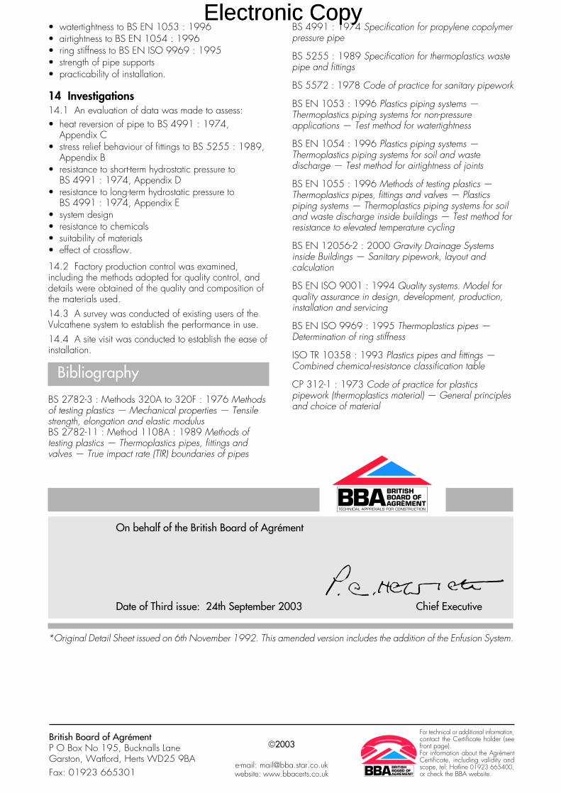
14 Procedure14.1 Typical laboratory bench waste runs areshown in Figures 3 and 4. The sinks, troughs anddrip cups are jointed to the traps by a 1½" BSPloose nut coupling. Typical sink and drip cupinstallation details are shown in Figure 5.
Electronic CopyElectronic Copy
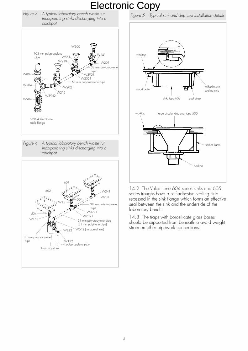
Figure 5 Typical sink and drip cup installation details
14.2 The Vulcathene 604 series sinks and 605series troughs have a self-adhesive sealing striprecessed in the sink flange which forms an effectiveseal between the sink and the underside of thelaboratory bench.
14.3 The traps with borosilicate glass basesshould be supported from beneath to avoid weightstrain on other pipework connections.
Figure 4 A typical laboratory bench waste runincorporating sinks discharging into acatchpot
Figure 3 A typical laboratory bench waste runincorporating sinks discharging into acatchpot
5
Electronic CopyElectronic Copy
Technical Investigations
The following is a summary of the technicalinvestigations carried out on the VulcatheneMechanical Laboratory Drainage System, Sinks,Troughs, Drip Cups and Traps.
15 Tests15.1 Tests were carried out to determine:dimensional accuracyflow capacitytightness of jointseffect of temperatureabrasion resistanceeffectiveness of standing waste tubes.
15.2 Tests were carried out on the traps todetermine:dimensional accuracyeffectiveness of dilution trapsease of maintenanceeffect of elevated temperature cycling to BS 3943 :
1979(1988), Appendix Bimpact resistance to BS 3943 : 1979(1988),
Appendix Chydrostatic pressure resistance to BS 3943 :
1979(1988), Appendix Eeffectiveness of water seal to BS 3943 :
1979(1988), Appendix Fflow of water to BS 3943 : 1979(1988),
Appendix G.
16 Other investigations16.1 An evaluation of data was made to assess:system designresistance to chemicalssuitability of materialseffect of crossflow.
16.2 Factory production control was examined,including the methods adopted for quality control,and details were obtained of the quality andcomposition of the materials used.
16.3 A survey was conducted of existing users ofthe Vulcathene system to establish the performancein use.
16.4 A site visit was conducted to establish theease of installation.
Bibliography
BS 1206 : 1974 Specification for fireclay sinks:dimensions and workmanshipBS 1244 Metal sinks for domestic purposesBS 1244-2 : 1988 Specification for sit-on andinset sinksBS 3943 : 1979(1988) Specification for plasticwaste trapsBS EN 12056 Gravity Drainage Systems insideBuildingsBS EN 12056-2 : 2000 Sanitary pipework, layoutand calculationBS EN ISO 9001 : 1994 Quality systems. Modelfor quality assurance in design, development,production, installation and servicing
ISO/TR 10358 : 1993 Plastics pipes and fittings— Combined chemical-resistance classificationtableCP 312 Code of practice for plastics pipework(thermoplastics material)CP 312-1 : 1973 General principles and choiceof materials
On behalf of the British Board of Agrément
Date of Second issue: 25th March 2002 Chief Executive
*Original Certificate issued on 6th November 1992. This amended version includes a revision and update to BS,BS EN and BS EN ISO references.
6
Electronic CopyElectronic Copy

7
Blank page
Electronic CopyElectronic Copy

British Board of AgrémentP O Box No 195, Bucknalls LaneGarston, Watford, Herts WD25 9BAFax: 01923 665301
©2002 For technical or additionalinformation, tel: 01923 665300.For information about AgrémentCertificate validity and scope, tel:Hotline: 01923 665400
e-mail: [email protected]: www.bbacerts.co.uk
Electronic CopyElectronic Copy

Readers are advised to check the validity of this Detail Sheet by either referring to the BBA’s website (www.bbacerts.co.uk) or contactingthe BBA direct (Telephone Hotline 01923 665400).
Technical Specification
1 Description1.1 The Vulcathene Mechanical LaboratoryDrainage System, Access Pipes comprises thefittings described in this Detail Sheet used inconjunction with the Vulcathene pipes and fittingsdescribed in additional Detail Sheets contained inthis Certificate.
1.2 The range of access pipes is shown inFigure 1. Access pipes are injection mouldedfrom black polyethylene and have spigot endssuitable for mechanical connection to otherVulcathene pipe fittings. Unit type W902 (51 mm)has a threaded screw-down cover. Units typesW903 (76 mm) and W904 (102 mm) eachhave a cover secured by brass nuts.
1.3 Factory production control of the Vulcathenesystem includes chemical evaluation of the rawmaterials and documented visual, weight anddimensional checks. There is a system to controlthe traceability and recalibration of test equipment.The Vulcathene (Glynwed Pipe Systems Ltd) qualitysystem is registered by BSI Quality Assurance toBS EN ISO 9001 : 1994).
2 Delivery and site handling2.1 The access pipes are marked with themanufacturer’s registered trademark and the nominalinternal diameter of the inlet and outlet connections.
2.2 The access pipes are robust but normal careis required in handling to prevent damage.
Figure 1 Access pipes
• THIS DETAIL SHEET RELATES TO THE VULCATHENE MECHANICALLABORATORY DRAINAGE SYSTEM, ACCESS PIPES.• The products are installed easily and joints will remain watertight underall normal service conditions.
This Detail Sheet must be read in conjunction with the Front Sheet, which givesConditions of Certification and the products' position regarding the BuildingRegulations.
Certificate No 92/2805
DETAIL SHEET 4Second issue*
Vulcathene
VULCATHENE MECHANICAL LABORATORY DRAINAGE SYSTEM,ACCESS PIPES
Product
CI/SfB
(52) In6
Electronic CopyElectronic Copy
Design Data
3 General3.1 Where the Vulcathene system is to beused in a laboratory application withchemical effluents not suitable for discharge
into a public sewer, the building drainage shouldrun to a holding tank. The local Water Authorityshould be consulted regarding details of theeffluents likely to be discharged into the laboratorydrainage system.
3.2 Vulcathene access pipes are satisfactory foruse in domestic, commercial and public buildingsin accordance with BS EN 12056-2 : 2000 forthe conveyance of domestic drainage and sewageas is permitted to be discharged into public sewersby the Public Health Act 1936 (England andWales), and sewage as is permitted and definedby the Sewerage (Scotland) Act 1968 and theWater and Sewerage Services (Northern Ireland)Order 1973.
4 Strength4.1 Vulcathene access pipes will haveadequate resistance to the forms of loadingassociated with installation.
4.2 The products should be protected fromimpacts, for example, from heavy vehicles such asfork-lift trucks used on commercial premises.
5 Performance of joints5.1 The joints will not be adversely affectedby thermal movement when correctly made.
5.2 The access cover seal will remain watertightafter removal and replacement of the cover formaintenance access.
6 Flow characteristicsThe internal dimensions of the access pipeswill not restrict the flow characteristics of thepipeline in which they are installed.
7 Resistance to chemicals7.1 The access pipes are resistant to awide range of noxious chemicals forlaboratory applications. The suitability of the
system for a particular application can bedetermined using CP 312-1 : 1973 and/orISO/TR 10358 : 1993.
7.2 The access pipes will be unaffected by thosetypes and quantities of chemicals likely to be foundin the effluents defined on the Front Sheet of thisCertificate.
8 Resistance to elevated temperaturesThe access pipes have adequate resistance tothe temperatures likely to occur in the effluentsdefined on the Front Sheet of this Certificate.
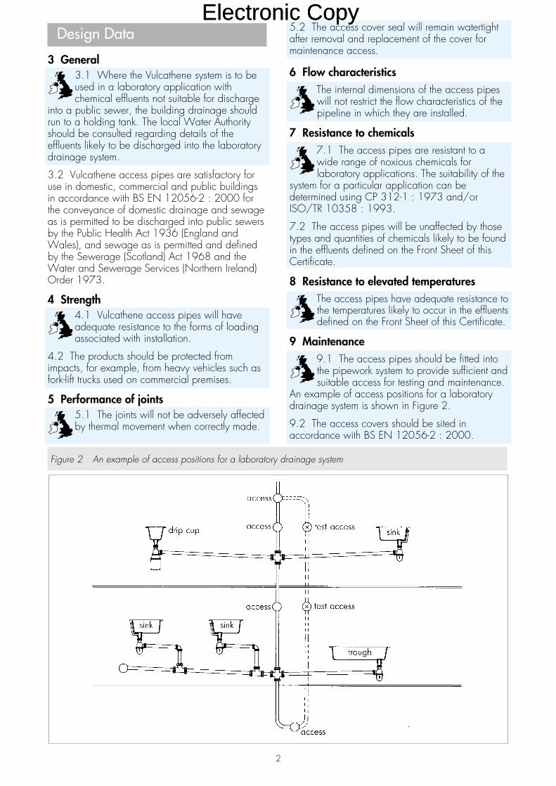
9 Maintenance9.1 The access pipes should be fitted intothe pipework system to provide sufficient andsuitable access for testing and maintenance.
An example of access positions for a laboratorydrainage system is shown in Figure 2.
9.2 The access covers should be sited inaccordance with BS EN 12056-2 : 2000.
2
Figure 2 An example of access positions for a laboratory drainage system
Electronic CopyElectronic Copy
10 DurabilityWhen used within the conditions andrecommendations given in this Detail Sheetthe access pipes will have a serviceable life
equivalent to conventional plastics drainagesystems. Prolonged exposure to strong oxidisingagents in a laboratory application may reduce theserviceable life of the system.
Installation
11 General11.1 Installation should be in accordance withBS EN 12056-2 : 2000 and the manufacturer’sTechnical Guide.
11.2 Where the Vulcathene system is to beenclosed in ducts they should provide easy accessfor maintenance, testing and cleaning. It isimportant to ensure that the access pipes are notobstructed by the installation of sanitaryappliances.
12 Procedure12.1 The spigot ends of the access pipes aregrooved at the factory. To assemble a joint, the nutis placed over the spigot end followed by an olive.Before making the joint to another Vulcathene fittingthe olive and fitting should be checked to ensurethat they are clean and free from dirt. The thread ofthe fitting is smeared with petroleum jelly, pushedover the olive and the nut tightened by hand.
12.2 For the other spigot end of the access pipe,the procedure described in section 12.1 isrepeated.
Technical Investigations
The following is a summary of the technicalinvestigations carried out on the VulcatheneMechanical Laboratory Drainage System, AccessPipes.
13 TestsTests were carried out to determine:dimensional accuracyease of removal of access cover for maintenanceease of roddingresistance to hydrostatic pressure to BS 4991 :
1974(1982)tightness of seal after removal and replacement of
cover.
14 Other investigations14.1 An evaluation of data was made to assess:system designresistance to chemicalssuitability of materials.
14.2 Factory production control was examined,including the methods adopted for quality control,and details were obtained of the quality andcomposition of the materials used.
14.3 A survey was conducted of existing users ofthe Vulcathene system to establish the performancein use.
14.4 A site visit was conducted to establish theease of installation.
3
Electronic CopyElectronic Copy

Bibliography
BS 4991 : 1974(1982) Specification forpropylene copolymer pressure pipes
BS EN 12056 Gravity Drainage Systems insideBuildingsBS EN 12056-2 : 2000 Sanitary pipework, layoutand calculation
BS EN ISO 9001 : 1994 Quality systems. Modelfor quality assurance in design, development,production, installation and servicing
ISO/TR 10358 : 1993 Plastics pipes and fittings— Combined chemical-resistance classificationtable
CP 312 Code of practice for plastics pipework(thermoplastics material)CP 312-1 : 1973 General principles and choiceof materials
On behalf of the British Board of Agrément
Date of Second issue: 25th March 2002 Chief Executive
*Original Certificate issued on 6th November 1992. This amended version includes a revision and update to BS,BS EN and BS EN ISO references
British Board of AgrémentP O Box No 195, Bucknalls LaneGarston, Watford, Herts WD25 9BAFax: 01923 665301
©2002For technical or additional information,contact the Certificate holder (seefront page).For information about the AgrémentCertificate, including validity andscope, tel: Hotline 01923 665400,or check the BBA website.
e-mail: [email protected]: www.bbacerts.co.uk
Electronic CopyElectronic Copy
Readers are advised to check the validity of this Detail Sheet by either referring to the BBA’s website (www.bbacerts.co.uk) or contactingthe BBA direct (Telephone Hotline 01923 665400).
Technical Specification
1 Description1.1 The Vulcathene Mechanical LaboratoryDrainage System, Floor Gullies comprises thefittings described in this Detail Sheet used inconjunction with the Vulcathene pipes and fittingsdescribed in additional Detail Sheets contained inthis Certificate.
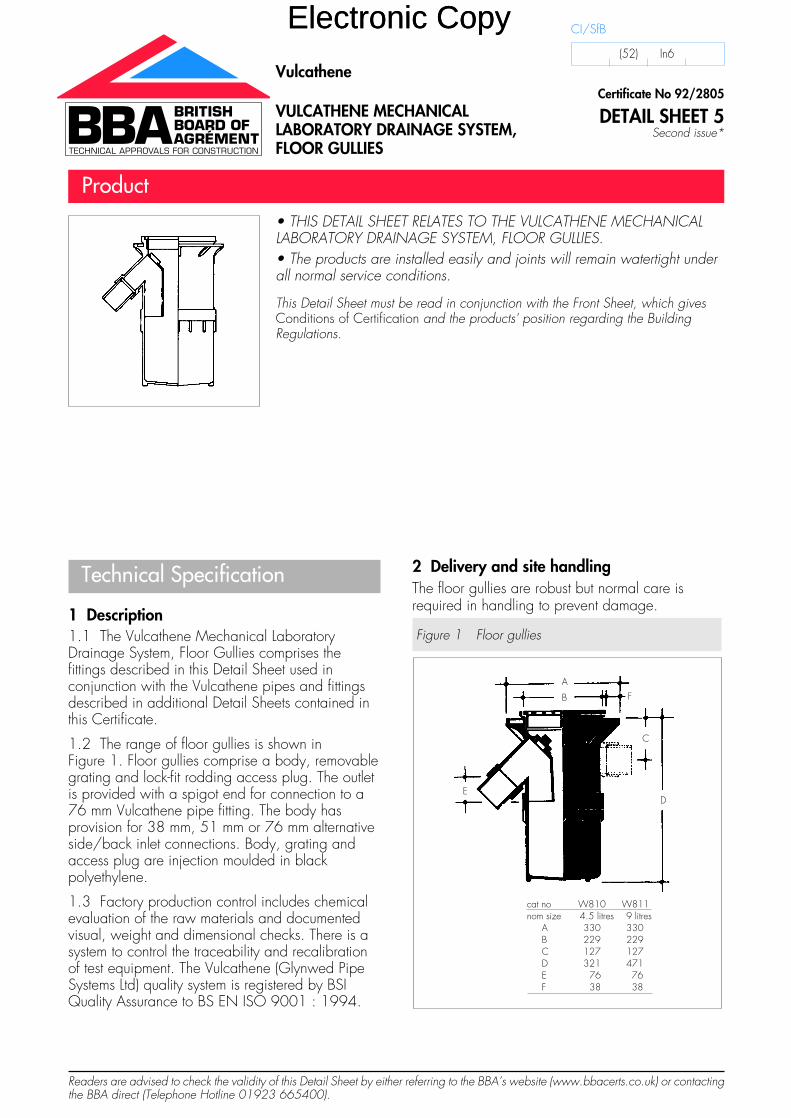
1.2 The range of floor gullies is shown inFigure 1. Floor gullies comprise a body, removablegrating and lock-fit rodding access plug. The outletis provided with a spigot end for connection to a76 mm Vulcathene pipe fitting. The body hasprovision for 38 mm, 51 mm or 76 mm alternativeside/back inlet connections. Body, grating andaccess plug are injection moulded in blackpolyethylene.
1.3 Factory production control includes chemicalevaluation of the raw materials and documentedvisual, weight and dimensional checks. There is asystem to control the traceability and recalibrationof test equipment. The Vulcathene (Glynwed PipeSystems Ltd) quality system is registered by BSIQuality Assurance to BS EN ISO 9001 : 1994.
2 Delivery and site handlingThe floor gullies are robust but normal care isrequired in handling to prevent damage.
Figure 1 Floor gullies
cat no W810 W811nom size 4.5 litres 9 litres
A 330 330B 229 229C 127 127D 321 471E 76 76F 38 38
A
B F
C
DE
• THIS DETAIL SHEET RELATES TO THE VULCATHENE MECHANICALLABORATORY DRAINAGE SYSTEM, FLOOR GULLIES.• The products are installed easily and joints will remain watertight underall normal service conditions.
This Detail Sheet must be read in conjunction with the Front Sheet, which givesConditions of Certification and the products' position regarding the BuildingRegulations.
Certificate No 92/2805
DETAIL SHEET 5Second issue*
Vulcathene
VULCATHENE MECHANICALLABORATORY DRAINAGE SYSTEM,FLOOR GULLIES
Product
CI/SfB
(52) In6
Electronic CopyElectronic Copy
Design Data
3 General3.1 Where the Vulcathene system is to beused in a laboratory application withchemical effluents not suitable for discharge
into a public sewer, the building drainage shouldrun to a holding tank. The local Water Authorityshould be consulted regarding details of theeffluents likely to be discharged into the laboratorydrainage system.
3.2 Vulcathene floor gullies are satisfactory for usein domestic, commercial and public buildings inaccordance with BS EN 12056-2 : 2000 for theconveyance of domestic drainage and sewage asis permitted to be discharged into public sewers bythe Public Health Act 1936 (England and Wales),and sewage as is permitted and defined by theSewerage (Scotland) Act 1968 and the Water andSewerage Services (Northern Ireland) Order 1973.
4 Strength4.1 When installed in accordance with therecommendations given in this Detail Sheetthe floor gullies will have adequate strength
to resist the loads normally encountered inhandling, installation and backfilling.
4.2 The floor gully grating is suitable for usewhere subject to foot traffic only.
5 Performance of jointsThe joints will not be adversely affected bythermal movement when correctly made.
6 Watertightness/airtightness6.1 Joints with the pipeline remainwatertight under conditions of pipelinemovement in excess of those expected to
occur in normal good drainage practice.
6.2 The seal of the lock-fit rodding access plugwill withstand the application of an air pressure of70 mm water gauge and will not therefore nullifythe effect of the water seal in the floor gullies.
7 Flow characteristicsThe satisfactory flow characteristics of the floorgullies minimise the risk of blockages. Whenmeasured with the flow entering the top grating themaximum flow capacity is 145 litres per minute.
8 Resistance to chemicals8.1 The Vulcathene system is resistant to awide range of noxious chemicals forlaboratory applications. The suitability of the
system for a particular application can bedetermined using CP 312-1 : 1973 and/orISO/TR 10358 : 1993.
8.2 The products will be unaffected by those typesand quantities of chemicals likely to be found in theeffluents defined on the Front Sheet of thisCertificate.
9 Resistance to elevated temperaturesThe products have adequate resistance tothe temperatures likely to occur in theeffluents defined on the Front Sheet of this
Certificate.
10 Practicability of installationInstallation of the floor gullies is achieved easilyunder normal site conditions.
11 Rodding11.1 The floor gullies provide adequateaccess for rodding the drain withconventional cane or polypropylene drain
rods (see section 12).
11.2 Care must be taken to avoid damage to thegully body when using rods with brass ferrules atthe joints.
12 MaintenanceThe floor gullies are cleaned easily by hand afterremoval of the grating.
13 DurabilityWhen used within the conditions andrecommendations given in this Detail Sheet thefloor gullies will have a serviceable life equivalentto conventional plastics drainage systems.
Installation
14 GeneralInstallation should be in accordance withBS EN 12056-2 : 2000.
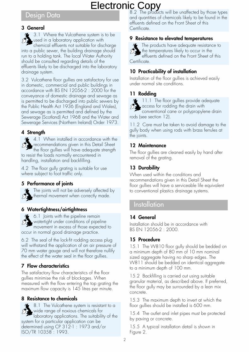
15 Procedure15.1 The W810 floor gully should be bedded ona minimum depth of 80 mm of 10 mm nominalsized aggregate having no sharp edges. TheW811 should be bedded on identical aggregateto a minimum depth of 100 mm.
15.2 Backfilling is carried out using suitablegranular material, as described above. If preferred,the floor gully may be surrounded by a lean mixconcrete.
15.3 The maximum depth to invert at which thefloor gullies should be installed is 600 mm.
15.4 The outlet and inlet pipes must be protectedby paving or concrete.
15.5 A typical installation detail is shown inFigure 2.
2
Electronic CopyElectronic Copy
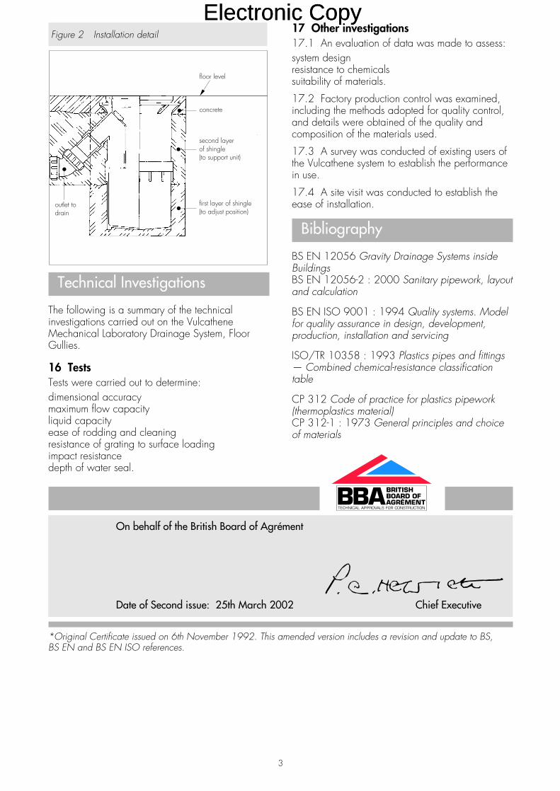
Figure 2 Installation detail
Technical Investigations
The following is a summary of the technicalinvestigations carried out on the VulcatheneMechanical Laboratory Drainage System, FloorGullies.
16 TestsTests were carried out to determine:dimensional accuracymaximum flow capacityliquid capacityease of rodding and cleaningresistance of grating to surface loadingimpact resistancedepth of water seal.
17 Other investigations17.1 An evaluation of data was made to assess:system designresistance to chemicalssuitability of materials.
17.2 Factory production control was examined,including the methods adopted for quality control,and details were obtained of the quality andcomposition of the materials used.
17.3 A survey was conducted of existing users ofthe Vulcathene system to establish the performancein use.
17.4 A site visit was conducted to establish theease of installation.
Bibliography
BS EN 12056 Gravity Drainage Systems insideBuildingsBS EN 12056-2 : 2000 Sanitary pipework, layoutand calculation
BS EN ISO 9001 : 1994 Quality systems. Modelfor quality assurance in design, development,production, installation and servicing
ISO/TR 10358 : 1993 Plastics pipes and fittings— Combined chemical-resistance classificationtable
CP 312 Code of practice for plastics pipework(thermoplastics material)CP 312-1 : 1973 General principles and choiceof materials
3
On behalf of the British Board of Agrément
Date of Second issue: 25th March 2002 Chief Executive
*Original Certificate issued on 6th November 1992. This amended version includes a revision and update to BS,BS EN and BS EN ISO references.
Electronic CopyElectronic Copy

British Board of AgrémentP O Box No 195, Bucknalls LaneGarston, Watford, Herts WD25 9BAFax: 01923 665301
©2002For technical or additional information,contact the Certificate holder (seefront page).For information about the AgrémentCertificate, including validity andscope, tel: Hotline 01923 665400,or check the BBA website.
e-mail: [email protected]: www.bbacerts.co.uk
Electronic CopyElectronic Copy