Embed Size (px)
Citation preview

www.danfoss.com
Electronic ControlsFitter’s Notes
MAKING MODERN LIVING POSSIBLE

2 DKRCC.PF.000.G2.02 / 520H8626
Fitter notes – Electronic Controls

DKRCC.PF.000.G2.02 / 520H8626 3
Fitter notes – Electronic Controls
Measuring 4Measuring a temperature 4Temperature sensor type EKS 111 5Temperature sensor type EKS 211 5Positioning sensors 6Evaporator positions 6S1 and S2 sensors 7How to mount S2 sensor on a vertical pipe 7How to mount S2 sensor on a horizontal pipe 7Measuring a pressure 8Positioning sensors 11Pressure transmitter in liquid line with pulse snubber 12
Electrical connections 13Pulse width modulation electronically operated expansion valve type AKV 13Stepper motor electronically operated expansion valve type ETS 13Digital Input (DI) / Digital Output (DO) 14No power 14Split sensors and AKV 14External Start/Stop of regulation 14
Controlling 15Input and output 15Operation 15Evaporator controls 16Parameters 16What is the controller doing...? 17Quick start 17What is wrong....? 18
Communication 19Why...? 19How…? 19Cable selection / termination 20Requirement to installation 20Cable 21Addressing 24Trouble shooting 24
Contents

4 DKRCC.PF.000.G2.02 / 520H8626
Fitter notes – Electronic Controls
R
NTC
PTC Pt
T
AKS 11, AKS 12, AKS 21, AK-HS 1000°C ohm °C ohma0 1000.0 1000.01 1003.9 -1 996.12 1007.8 -2 992.23 1011.7 -3 988.34 1015.6 -4 984.45 1019.5 -5 980.46 1023.4 -6 976.57 1027.3 -7 972.68 1031.2 -8 968.79 10.35.1 -9 964.810 1039.0 -10 960.911 1042.9 -11 956.912 1046.8 -12 953.013 1050.7 -13 949.114 1054.6 -14 945.215 1058.5 -15 941.216 1062.4 -16 937.317 1066.3 -17 933.418 1070.2 -18 929.519 1074.0 -19 925.520 1077.9 -20 921.621 1081.8 -21 917.722 1085.7 -22 913.723 1089.6 -23 909.824 1093.5 -24 905.925 1097.3 -25 901.926 1101.2 -26 898.027 1105.1 -27 894.028 1109.0 -28 890.129 1112.8 -29 886.230 1116.7 -30 882.231 1120.6 -31 878.332 1124.5 -32 874.333 1128.3 -33 870.434 1132 -34 866.434 1132.2 -34 866.435 1136.1 -35 862.536 1139 -36 858.537 1143.8 -37 854.638 1147.7 -38 850.639 1151.5 -39 846.740 1155.4 -40 842.741 1159.3 -41 838.842 1163.1 -42 835.043 1167.0 -43 830.844 1170.8 -44 826.945 1174.7 -45 822.946 1178.5 -46 818.947 1182.4 -47 815.048 1186.3 -48 811.049 1190.1 -49 807.050 1194.0 -50 803.1
approx 3.9 ohm/K
Note
Up to 50m use 0.75mm²Up to 100m use 1.5mm²Up to 150m use 2.5mm²
The typical resistance values for cables are: y -2.4Ω/100m for core cross-sectional area of 0.75mm². y -1.2Ω/100m for core cross-sectional area of 1.5mm². y -0.7Ω/100m for core cross-sectional area of 2.5mm² .
Temperature sensor type: AKS11, AKS12, AKS21, AK-HS 1000
Pt sensorThese sensors are also known as RTD´s, Resistance Temperature Detectors. The sensing elements is made of platinum, example PT1000, where the number describes the nominal resistance at 0°C, here 1.000Ω. The resistance increases 4Ω per 1°C. The sensor characteristic is linear. In Danfoss these sensors are the type AKS.The tolerance of a Pt1000 sensor is less than ± (0.3 + 0.005 T).This translates into a temperature error of less than 0.5 degree for refrigeration control.The Pt1000 sensor must be used for food safety logs and regulation of superheat as they conform to the tolerance requirements of EN 60751 Class B and therefore satisfy the HACCP requirements of EN 12830, EN 13485.Extension of sensor cablesWhen extending a sensor cable, the new resistance value of the longer cable may give rise to indication error. It is recommended that the total cable resistance should not exceed 2Ω corresponding to an indication error of 0.5°C (Pt1000Ω).
MeasuringMeasuring a temperature
Pressure temperature inputsWith the use of electronic controllers such as Danfoss ADAP-KOOL® products the installation requirements must be followed to ensure the electrical connections, pressure and temperature sensors and any communication network connections are correct so that the unit operates as intended. The following are some general guidelines:
y Pressure temperature inputs It is very important that the correct type of temperature sensor is used for the temperature range, sensing application, and the temperature sensor signal is compatible with the electronic refrigeration controller, (please see the technical manual for the controller to ensure the correct temperature sensor is used).
y Sensor types The product programme of temperature sensors for refrigeration consists of two main families: AKS and EKS. These sensor elements are based on the three technologies: Pt, PTC and NTC.

DKRCC.PF.000.G2.02 / 520H8626 5
Fitter notes – Electronic Controls
Temperature sensor type EKS 211
NTC sensorThe sensing element in NTC´s is a thermistor having a negative temperature coefficient. The sensor characteristic is described by a number, that as with PTC´s, indicates the nominal resistance at 25°C, and by a β-value which defines the curve characteristic.Due to the variety of characteristics it is not possible to develop a standard NTC sensor that can be used for all controller types. Hence, when making service you must install an “original” NTC sensor to ensure the controller to work properly.
Temperature sensor type EKS 211NTC characteristic matches controllers type EKC and AK-CC.The NTC temperature sensor type EKS211 must not be used for food safety logs as they do not conform to the requirements EN 12830, EN 13485 or regulation of superheat because they do not have the needed accuracy of +/- 0.5K.
Temperature sensor type EKS 111
PTC sensorThe PTC sensor got their name as the sensing element has a positive temperature coefficient.The sensing element is a semi conductor, example PTC1000 where the number describes the nominal resistance at 25°C.The sensor characteristic is almost linear but is not standardized, the manufacturer can define their own characteristics.
In Danfoss the EKS111 is a PTC1000 type.The PTC temperature sensor type EKS111 must not be used for food safety logs as they do not conform to the requirements EN 12830, EN 13485 or regulation of superheat because they do not have the needed accuracy of +/- 0.5K.
R (typ.) Ohm Temp. °C Error K Temp °F
1679 100 +/-3.5 212
1575 90 194
1475 80 176
1378 70 158
1286 60 140
1196 50 122
1111 40 104
1029 30 86
990 25 +/-1.3 77
951 20 68
877 10 50
807 0 32
740 -10 14
677 -20 -4
617 -30 -22
562 -40 -40
510 -50 -58
485 -55 +/-3.0 -67
R_nom Ohm Temp. °C Temp °F
631.0 80 176
743.2 75 167
878.9 70 158
1044 65 149
1247 60 140
1495 55 131
1803 50 122
2186 45 113
2665 40 104
3266 35 95
4029 30 86
5000 25 77
6246 20 68
7855 15 59
9951 10 50
12696 5 41
16330 0 32
21166 -5 23
27681 -10 14
36503 -15 5
48614 -20 -4
65333 -25 -13
88766 -30 -22
121795 -35 -31
169157 -40 -40
6 DKRCC.PF.000.G2.02 / 520H8626
Fitter notes – Electronic Controls
Ø=12 - 16mm
12 123
4
1
in.1 2 5 8
Ø=18 - 26mm
in.3 4 1 8
12 123
4
Ø=6.5
NB!
S6 S4
S2Pe
S5
S3
Po PcSd
M M
SS
SCS
Positioning sensors
It is very important that during the installation process and also during maintenance schedules the correct position and mounting of all temperature sensors is in line with the recommendations. Incorrect mounting can cause faulty temperature signals to be used by the controller which will result in, in-correct operation of the refrigeration application.
Evaporator positions
Nomenclature of temperature tensors & pressuretransmitters in Danfoss controllers
y S1: Temperature sensor measuring evaporating temperature (Can be used as a less accurate measurement of evaporating temperature without the need for a pressure transmitter)
y Pe: Pressure transmitter measuring true evaporating pressure (preferred method)
y S2: Suction temperature outlet of the evaporator y S3: Air entering the evaporator y S4: Air leaving the evaporator y S5: Defrost termination temperature sensor when defrost is
being used y S6: Is used as a product sensor (type AK-HS1000,HACCP
compliance for food safety)
Pack positions y Po: Pressure transmitter - Suction pressure y Pc: Pressure transmitter - Discharge pressure y Ss: Temperature sensor - Suction temperature to work out
suction superheat in connection with suction pressure Po y Sd: Temperature sensor - Discharge temperature y Sc3: Temperature sensor - Ambient temperature of the air
entering the condenser

DKRCC.PF.000.G2.02 / 520H8626 7
Fitter notes – Electronic Controls
S1
S1 S1A BS1B
Where and how to mount the S1 sensor
S2 B
S2 A
Where and how to mount the S2 sensor
Mount on vertical pipe if possible not too close to bendand not to far from evaporator outlet
S2
A A The sensor should bemounted rmly on thepipe using heat-conductingpaste and the sensorshould be insulated
Cut A-A
Pipe isolation
Oil splash can disturb the signal
S2 sensorCut A-A
S2B
B
The sensor should bemounted rmly on thepipe using heat-conductingpaste and the sensorshould be insulated
Cut B-B
S2 sensor
Pipe
Isolation
S1 and S2 sensors
S1 and S2 sensors measuring saturation temperature and temperature of superheat gasses.
y S1: This sensor is measuring the evaporating temperature of the evaporator and therefore must be mounted on the coldest point on the evaporator, normally the first return bend. The reading should be checked against the suction gauge pressure to confirm that the pressure and temperature relationship is correct otherwise the control of superheat will be incorrect.
y S2: Sensor function is to measure the temperature of the refrigerant exiting at the evaporator’s pipe outlet and, has thus, the same goal as a thermostatic expansion valve’s bulb and should be placed exactly according to the same rules. Only a Pt1000 AKS11 type sensor must be used, as it is the only type providing the necessary accuracy needed for this purpose.
How to mount S2 sensor on a vertical pipe
Steel pipesIf steel pipes are used on the evaporator outlet the superheat signal it must be measured using a pocket sensor “S2” to get a correct signal. This is absolutely necessary to get a good injection control.
Copper pipes (exceeding 50mm)When pipe dimensions go up so does the material thickness. Bigger thickness also means greater temperature difference between inner and outer temperatures. You should use immersion pocket sensors here also.
How to mount S2 sensor on a horizontal pipe
When mounted on horizontal pipe the position depends on the size of the pipe.
y Mount at 1 o’clock when diameter is between 1/2 and 5/8inch (12-16mm).
y Mount at 2 o’clock when diameter is between 3/4 and 1- 1/8inch (18-26mm).
y Mount at 4 o’clock when diameter is over 1- 1/2inch (38mm). y Use immerse pocket sensor if you want to measure on steel
pipe.

8 DKRCC.PF.000.G2.02 / 520H8626
Fitter notes – Electronic Controls
Measuring a pressure
It is very important that the correct type of pressure transmitter is used for the pressure range, sensing application, and the pressure transmitter signal is compatible with the electronic refrigeration controller, (please see the technical manual for the controller to ensure correct pressure transmitter is used).
AKS ratiometricType Operating range [bar] Permissible working pressure
PB [bar]
AKS 2050 -1 to 59 100
-1 to 99 150
-1 to 159 250
AKS 32, version 1-5V
Operating range Max working pressure PB
LP-1 --> 6 [bar] 33 [bar]
-1 --> 12 [bar] 33 [bar]
HP-1 --> 20 [bar] 40 [bar]
-1 --> 34 [bar] 55 [bar]
AKS 32, version 0-10V
Operating range Max working pressure PB
LP-1 --> 5 [bar] 33 [bar]
-1 --> 9 [bar] 33 [bar]
HP-1 --> 21 [bar] 10 [bar]
-1 --> 39 [bar] 60 [bar]
AKS 33, version 4-20mA
Operating range Max working pressure PB
LP
-1 --> 5 [bar] 33 [bar]
-1 --> 6 [bar] 33 [bar]
-1 --> 9 [bar] 33 [bar]
-1 --> 12 [bar] 33 [bar]
-1 --> 20 [bar] 40 [bar]
HP
-1 --> 34 [bar] 55 [bar]
0 --> 16 [bar] 40 [bar]
0 --> 25 [bar] 40 [bar]

DKRCC.PF.000.G2.02 / 520H8626 9
Fitter notes – Electronic Controls
Pressure transmitter Range and types of signals
A pressure transmitter will measure the pressure and this measurement will be conditioned in the form of a defined electrical signal that will allow it to be “transmitted” on a further distance. A pressure transmitter needs a power supply, most of the time this is going to be provided from the controller it is connected to.Don’t forget that sensors, in general, are the “eyes” of a controller.The better they are selected and positioned, the better the controller is able to do its job!
Two main data will be needed to define a pressure transmitter:1. The pressure range, depending on the application where the
pressure transmitter is needed. In traditional refrigeration system, mostly two different ranges of pressures will be found, the evaporating pressure (LP) and the condensing pressure (HP). This is happening at rather different pressure levels so the pressure range of the pressure transmitter for the low pressure side will be different than the one for the high pressure side. Typically, a range from -1 to 12bar is used for the low pressure side and a range of -1 to 34bar is used on the high pressure side. It is important, for the accuracy of the signal, that the range is properly selected according to the application. Example: If you need to measure a pressure of 5bar, a pressure transmitter of -1 to 12bar will give you a much better accuracy than one of -1 to 34bar.
2. The type of electrical signal, can be either in current [mA] or voltage [V]. The two first types mentioned, the electrical signal issued is directly proportional to the pressure only. How to find the value of the expected signal for a known pressure? Example: A pressure transmitter with a range -1 to 12bar is used. The pressure in the system is 5bar. The total pressure range is thus from -1 to 12bar making a total of 13bar (+12-(-1)). For a 4-20mA transmitter, a signal of 4mA will be issued for a pressure of -1bar and 20mA will be for 12bar. The current output range is from 4 to 20mA making a total range of 16mA (20-4). We divide the 16mA by 13bar, and this will give us 1,23mA/bar. We multiply now by the number of bar starting from -1bar, thus 1+5 = 6bar by 1,23. Results = 7.38mA and we finally add the starting point of 4mA (not “0” !!) to give us the final answer of 11,38mA for a pressure of 5bar. This value can be easily controlled by using a ammeter in series with the sensor’s wires. For a 0-10V transmitter, a signal of 0V will be issued for a pressure of -1bar and 10V will be for 12bar. The total pressure range is thus from -1 to 12bar making a total of 13bar (+12-(-1)). The voltage output range is from 0 to 10V making a total range of 10V. We divide the 10V by 13bar, and this will give us 0.77V/bar. We multiply now by the number of bar starting from -1bar, thus 1+5 = 6bar by 0.77. Results = 4.62V for a pressure of 5bar. This value can be easily controlled by using a voltmeter on the sensor’s wires.
4-20mA output, 2 wires (+,-)
RL
UB
1
2
3
0-10V or 1-5V output, 3 wires (+, s, -)
RL
UB
1
2
3

10 DKRCC.PF.000.G2.02 / 520H8626
Fitter notes – Electronic Controls
For ratiometric transmitter, the ratio metric transmitter, the output signal is not only proportional to the pressure but is also directly depending of the voltage on the power supply. This is the type that is commonly used on most of the controllers. The output signal of the transmitter will be presented as a percentage of the voltage of the power supply Example: 10….90% of [V] supply. For a ratiometric transmitter, let’s take an example: a pressure transmitter with a range -1 to 12bar is used. The pressure in the system is 5bar and the power supply is of 5VDC. The lowest signal will be for -1bar and will correspond to 10% of the power supply, thus 0.5V. The highest signal will be for 12bar and will correspond to 90% of the power supply, thus 4.5V. A signal of 0.5V will be issued for a pressure of -1bar and 4.5V will be for 12bar. The total pressure range is thus from -1 to 12bar making a total of 13bar (+12-(-1)). The voltage output range is from 0.5V to 4.5V making a total range of 4V (4.5-0.5). We divide the 4V by 13 (bar), and this will give us 0.3V/bar. We multiply now by the number of bar starting from -1 bar, thus 1+5 = 6bar by 0.3. Results = 1.8V and we finally add the starting point of 0.5V (not “0” !!) to give us the final answer of 2.3V for a pressure of 5bar. This value can be easily controlled by using a voltmeter on the sensor’s wires but you need to measure not only the signal but also the value of the power supply to ensure a correct answer
Ratio metric [V] output, 3 wires (+, s, -)
RL
UB
1
2
3

DKRCC.PF.000.G2.02 / 520H8626 11
Fitter notes – Electronic Controls
Positioning sensors
Sensor mountingIt is very important that during the installation process and also during maintenance schedules the correct position and mounting of all pressure transmitters is in line with the recommendations. Incorrect mounting can cause faulty pressure signals to be used by the controller which will result in, in-correct operation of the refrigeration application.
Cable versionThe pressure transmitter must be mounted before the cable is fastened to avoid twisting the cable.
OrientationCan be mounted horizontal or vertical but with the pressure connection facing downwards, example not on the bottom of the pipe to avoid oil or dirt contamination. Plug cable facingdownwards prevents water collection in the cable entry.
Hot gas pipeUse a distance sleeve to reduce the temperature influence on hot gas lines to avoid overheating the pressure transmitter.

12 DKRCC.PF.000.G2.02 / 520H8626
Fitter notes – Electronic Controls
Pressure transmitter in liquid line with pulse snubber
y Cavitation, liquid hammer and pressure peaks may occur in liquid filled systems with changes in flow velocity, example fast closing of a valve or pump starts and stops. The problem may occur on the inlet and outlet side, even at rather low operating pressures.
y Pressure pulsations do not normally limit the pressure sensor lifetime, however for the sake of the controller or the pressure display equipment it may be expedient to dampen or filter the signal from the pressure sensor.
y Dampening can be performed by electronics in the controller equipment, or by means of connecting the sensor to the plant through normal damping coils (capillary tubes).
y It is also possible to order specific pressure transmitters which have a damping orifice fitted.
If a control valve is mounted on an evaporator, a separate pressure measurement will have to be made for the other controllers on the common suction if the evaporator controllers are of course using a pressure transmitter to measure the evaporating temperature.
Damping orice
AKS 32R
AKS 32R
AKS 32R

DKRCC.PF.000.G2.02 / 520H8626 13
Fitter notes – Electronic Controls
15
14
230V d.c.
L
ETS
L
ETSAKA 211
L < 5m
5m < L < 50m
ETS
AKA 2114x10mH
230V a.c.~~
5 6
230V a.c. coil
Electrical connectionsPulse width modulation electronically operated expansion valve type AKV
Using AC coil (alternating current)On present controllers (AK-CC) you find the electronic contact which switches the power to the AC coil.
Stepper motor electronically operated expansion valve type ETS
On some controllers the length between the controller and the valve ETS have to be max 5m.If the cable distance is greater than 5m a filter need to be used on some controllers to extend the cabling up to 50m.Find more information in the Instruction or Manual of the specific controller.
FilterThe filter has to placed beside the controller.
Using DC coil (direct current)In previous controllers (AKC or EKC) the supply came directly from the controller to the DC coil.
Note
Do not use a switch between the output and AKV coil.

14 DKRCC.PF.000.G2.02 / 520H8626
Fitter notes – Electronic Controls
Digital Input (DI) / Digital Output (DO)
Digital Output NC/NOYou must be aware, which type of contact do you have.
No power
GenerallyThe drawings ( especially the digital outputs ) of the electrical connections are always shown without connected power supply.
External Start/Stop of regulation
Some controllers can be started and stopped externally via a contact function connected to input terminals.The function must be used when the compressor is stopped.The controller then closes the solenoid valve so that the evaporator is not charged with refrigerant.
Split sensors and AKV
Temperature sensorEach controller needs its own temperature sensor input.
Pressure transmitterThe signal from one ratiometric pressure transmitter can be received by up to 10 controllers. But only if there are no significant pressure difference between the evaporators to be controlled.
AKVUse only one AKV coil for one solid state output. (“Pulse width modulation electronically operatedexpansion valve type AKV“) on page 13.
Digital Input powerless contacts
~ ~ Relay orAKV coil110/230V
3132 33 39 40 41 42 43 44 45 46 47 48 49 50
C
24
NO NC
25 16 17 18 19
1
Start/Stop
The signal from one pressure transmittercan be received by up to ten controllers
AKS 32R info
AKS 32R info
blac
k
blue
brow
n
30 31 32+ s
30 31 32+ s
+ - out1 2 3
1 2 3
24 25
DI1 DI21
SIG GND
V/Ω
Ω
24 25
Solid State Output DO1 (for AKV coil) Max 240V a.c.MAx 0.5 ALeak < 1mAMax 1 pcs. AKV
DKRCC.PF.000.G2.02 / 520H8626 15
Fitter notes – Electronic Controls
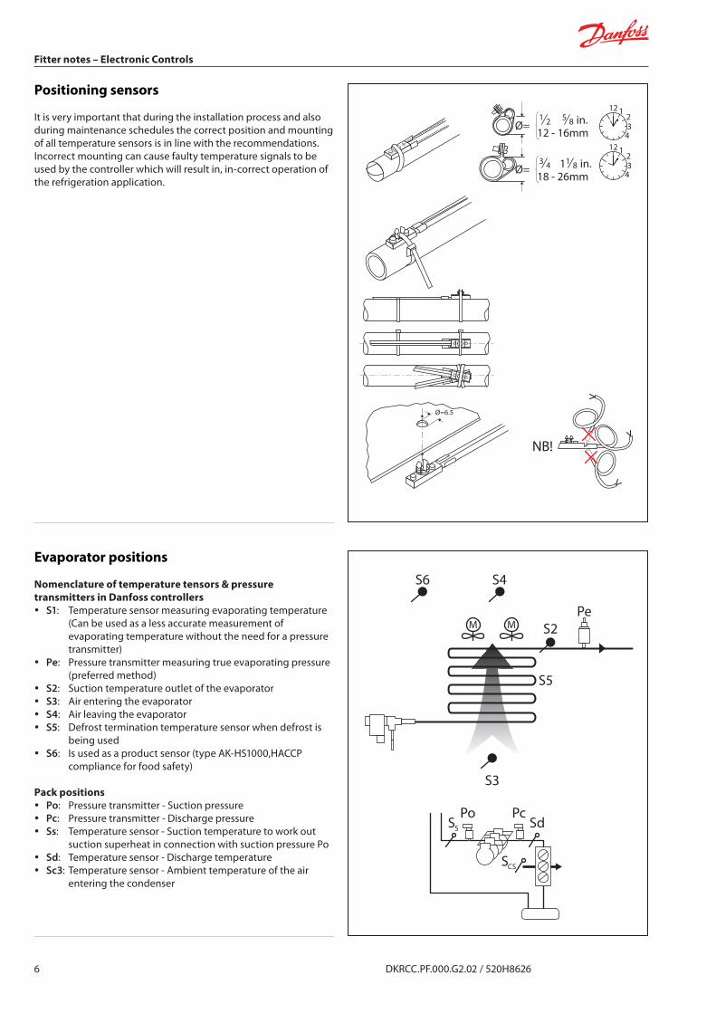
ControllingInput and output
Electronic controllers will have a number of inputs and outputs that will allow the measurement and control of several tasks related to refrigeration, mostly for evaporators and packs.
Inputs can roughly be divided in 2 types: y Analog inputs that are typical for either temperature or
pressure sensors, readings being °C/°F or bar/psi, (see MEASURING).
y Digital inputs that are typical for contact or voltage detection, readings being an ON/OFF results, (see CONNECTION).
Outputs can be divided in several types like: y Digital outputs that are typically electromechanical relays. y Electronics outputs generating pulses signals typically for
controls of electronic expansion valves like AKV (pulse width modulation) or ETS (stepper motor).
y Analog outputs generating mostly a 0 to 10VDC signal available either as information or additional controls.
See the example beside
Operation
DisplayThe values will be shown with three digits, and with a setting you can determine whether the temperature is to be shown in °C orin °F.
Light-Emitting Diodes (LED) on front panelThe LED’s on the front panel will light up when the relevant relay is activated.The light-emitting diodes will flash when there is an alarm.In this situation you can download the error code to the display and cancel/sign for the alarm by giving the top button a brief push.
The buttonsWhen you want to change a setting, the upper and the lower buttons will give you a higher or lower value depending on the button you are pushing. But before you change the value, you must have access to the menu. You obtain this by pushing the upper button for a couple of seconds, you will then enter the column with parameter codes. Find the parameter code you want to change and push the middle buttons until value for the parameter is shown. When you have changed the value, save the new value by once more pushing the middle button.
Examples:Set menu1. Push the upper button until a parameter r01 is shown2. Push the upper or the lower button and find that parameter you
want to change3. Push the middle button until the parameter value is shown4. Push the upper or the lower button and select the new value5. Push the middle button againt to freeze the value
Cutout alarm relay/receipt alarm/see alarm code y A short press of the upper button If there are several alarm codes
they are found in a rolling stack. Push the uppermost or lowermost button to scan the rolling stack.
1
S2
S2 S3
18 19 20 21 22 23 24 25 26
S3
whiteblackredgreen
ETS
RefrigerationDefrostFan running

16 DKRCC.PF.000.G2.02 / 520H8626
Fitter notes – Electronic Controls
Set temperature1. Push the middle button until the temperature value is shown2. Push the upper or the lower button and select the new value3. Push the middle button again to conclude the setting
Reading the temperature at defrost sensor (Or product sensor, if selected in “o92”)
y A short press of the lower button
Manuel start or stop of a defrost (Or product sensor, if selected in “o92”)
y Push the lower button for four seconds
Evaporator controls
Controllers for evaporators have built in functionalities that allow them to perform the necessary tasks for the control of the application including evaporators like cold rooms, cases, etc.Being electronic, allow them a large choice in the availablefunctionalities under a very compact format, this is giving a lot offlexibility in their use.Access to the functionalities is easily made through the use of adisplay and keys, allowing access to a list containing the different parameters. Basically, no “programming” is necessary, just setting of parameters values. An explanation on how to accessparameters via display and keys is shown beside.
Parameters
Parameters are placed in “groups” related to their functions.Example:Thermostat related functions are all placed in the group of parameters starting with letter “r” followed by a number.
Access to the thermostat differential is done via parameter “r01” and the value is expressed in degree Kelvin (to show it’s a difference). In all available controllers, “r01” will be referring to the differential therefore making the use of different controllers much easier. And so on for the others parameters.
y Group “r..” refers to thermostat related functions. y Group “A..” refers to Alarms setting and functions. y Group “C..” refers to Compressor management. y Group “D..” refers to Defrost functions. y Group “F..” refers to Fan functions. y Group “h..” refers to HACCP temperature. y Group “n..” refers to setting linked with the use of electronic
expansion valves. y Group “t” refers to the real-time clock. y Group “o..” refers to miscellaneous functions like addressing,
door functions, refrigerant, etc.
Beside parameters, readings are available in the “u..” group allowing to access sensors readings and Input/output status like opening degree of an electronic expansion valve or superheat value. These are usefully indications for the service technician, allowing him to see what the controller “sees” and helping drawn a fast diagnostic in case of problems.
Continued Code 1 2 3 4 5 6 7 8 9 10ServiceTemperature measured with S5 sensor u09 1 1 1 1 1 1 1 1 1 1Status on DI1 input. on/1=closed u10 1 1 1 1 1 1 1 1 1 1Actual defrost time (minutes) u11 1 1 1 1 1 1 1 1 1 1Temperature measured with S3 sensor u12 1 1 1 1 1 1 1 1 1 1Status on night operation (on or off) 1=on
u13 1 1 1 1 1 1 1 1 1 1
Temperature measured with S4 sensor u16 1 1 1 1 1 1 1 1 1 1Thermostat temperature u17 1 1 1 1 1 1 1 1 1 1Run time of thermostat (cooling time) in minutes
u18 1 1 1 1 1 1 1 1 1 1
Temperature of evaporator outlet temp.
u20 1 1 1 1 1 1 1 1 1 1
Superheat across evaporator u21 1 1 1 1 1 1 1 1 1 1Reference of superheat control u22 1 1 1 1 1 1 1 1 1 1Opening degree of AKV valve ** u23 1 1 1 1 1 1 1 1 1 1Evaporating pressure Po (relative) u25 1 1 1 1 1 1 1 1 1 1Evaporator temperature To (Calculated)
u26 1 1 1 1 1 1 1 1 1 1
Temperature measured with S6 sensor (product temperature)
u36 1 1 1 1 1 1 1 1 1
Status on DI2 output. on/1=closed u37 1 1 1 1 1 1 1 1 1 1Air temperature . Weighted S3 and S4 u56 1 1 1 1 1 1 1 1 1 1Measured temperature for alarm thermostat
u57 1 1 1 1 1 1 1 1 1 1
Status on relay for cooling ** u58 1 1 1 1Status on relay for fan ** u59 1 1 1 1 1 1 1 1 1 1Status on relay for defrost ** u60 1 1 1 1 1 1 1 1 1Status on relay for rail heat ** u61 1 1 1 1 1 1 1Status on relay for alarm ** u62 1 1 1 1 1Status on relay for light ** u63 1 1 1 1 1 1 1 1Status on relay for valve in suction line ** u64 1

DKRCC.PF.000.G2.02 / 520H8626 17
Fitter notes – Electronic Controls
What is the controller doing...?
Through status codes, the controller keeps you informed about his present behavior.Example:“S11” indicate that refrigeration has stopped after reaching thermostat cutout.“S14” would indicate that a defrost is in progress.
S0 Normal regulation S23 Adaptive control S46
S1 Waiting for the end of the coord def. S24 Start up phase: signal reliability S47
S2 Comp. must run for at least x min S25 Manual control of outputs S48
S3 Comp. must remain stop for x min S26 No refrigerant selected S49
S4 Evaporator drips OFF S27 Forced cooling S50
S5 Renewed cuting of relay wait x min S28 Stopped regulation S51
S6 Day operation (Sout control) S29 Case cleanig procedure S52
S7 Night operation (sin control) S30 Forced cooling S53
S8 Next relay must not cutin until x min S31 Door is oper (DI open) S54
S9 Nerxt relay must not cutout until x min S32 Delay on outputs during start up S55
S10 Stopped by mainswitch “r12” or DI S33 Heat function “r36” is active S56
S11 Refrig. stopped by thermostat S34 Safety cutout S57
S12 Refrig. stopped due to low sair S35 Cooling ON section B S58
S13 Defrost KVQ valve is closing S36 Cooling OFF section B S59
S14 Defrost in progress S37 Cooling ON section C S60
S15 Defrost sequence: fan delay S38 Cooling OFF section C S61
S16 Refrig. stopped by ON input S39 Cooling ON section D S62
S17 Door is open. DI input is open S40 Cooling OFF section D S63
S18 Melt function S41 S64
S19 Modulating thermostat control S42 S65
S20 Emergency cool sensor error S43 S66
S21 Injection problems S44 S67
S22 Start up: evaporator beign charged S45 S68
Quick start
Before allowing the controller to start the regulation, it is important to check if the controller readings are showing the right measurements. (“u”, see chapter “Parameters” at page 16).
Accessing the “u” readings in the service group, allow you to check this.Use the instruction sheet of the specific controller to locate the “u” readings corresponding to the connected sensors and contacts.
y Begin with checking that parameter “r12” (main switch) is set to OFF(0), that will stop the regulation.
y When done, ensure that the proper selection of the electrical diagram for the outputs has be done via the parameter “o61”.
y An easy way would then be to use preselected settings for your application room/case/cooling/freezing via the parameter “o62”.
y Setting parameter “r12” to ON(1) will then start the regulation with immediate effect.
100% tightThe buttons and the seal are imbedded in the front.A special moulding technique unites the hard front plastic, thesofter buttons and the seal, so that they become an integralpart of the front panel. There are no openings that can receive moisture or dirt.

18 DKRCC.PF.000.G2.02 / 520H8626
Fitter notes – Electronic Controls
What is wrong....?
In case of a default, Error and Alarm codes will be shown pointing directly to the problem.Example:“A1” will tell you that the alarm temperature has been reached. “E8” shows that the “S4” temperature sensor wiring is short-circuited.
A1 High temperature alarm A24 Compressor 6 fault A47 Fan 6 fault
A2 Low temperature/P0 alarm A25 Compressor 7 fault A48 Fan 7 fault
A3 Alarm level limit reached A26 Compressor 8 fault A49 Fan 8 fault
A4 Door alarm A27 Housing temperature A50 Saux1 temperature
A5 Max hold time/Slv def time-out A28 Digital input 1 alarm A51 DO1 fault
A6 “S4” out high temperature A29 Digital input 2 alarm A52 DO2 fault
A7 “S4” out low temperature A30 Digital input 3 alarm A53 DO3 fault
A8 “S3” in high temperature A31 Digital input 4 alarm A54 DO4 fault
A9 “S3” in low temperature A32 Digital input 5 alarm A55 DO5 fault
A10 Injection problem A33 Configuration change A56 DO6 fault
A11 No refrigerant selected A34 Fan 1 fault A57 DO7 fault
A12 Digital input alarm A35 Fan 2 fault A58 DO8 fault
A13 High temperature “S6” A36 Fan 3 fault A59 Case cleaning (DI input)
A14 Low temperature “S6” A367 Fan 4 fault A60 HACCP alarm
A15 Digital input 1 alarm A38 Fan 5 fault A61 Condenser alarm
A16 Digital input 2 alarm A39 Fan 6 fault A62 High T1 alarm
A17 Pc high alarm A40 Fan 7 fault A63 Low T1 alarm
A18 Pc low alarm A41 Fan 8 fault A64 High T2 alarm
A19 Compressor 1 fault A42 Amb. mode A65 Low T2 alarm
A20 Compressor 2 fault A43 Stepper motor alarm A66 High T3 alarm
A21 Compressor 3 fault A44 Battery alarm A67 Low T3 alarm
A22 Compressor 4 fault A45 Standby mode (“r12” or DI) A68 High temperature B
A23 Compressor 5 fault A46 Fan 5 fault A69 Low temperature
A70 High temperature C E1 Faults in the controller E24 Sensor “S2” error
A71 Low temperature C E2 Air sensor open circuit E25 Sensor “S3” error
A72 High temperature D E3 Air sensor short circuit E26 Sensor “S4” error
A73 Low temperature D E4 Defrost sensor open circuit E27 Defrost sensor “S5” error
A74 Adaptive defrost fault E5 Defrost sensor short circuit E28 Product sensor “S6” error
A75 Adaptive defrost evaporator iced E6 Realtime clock error (battery) E29 Sensor Sair error
A76 Adaptive Defrost not defrosted E7 “S4” out sensor open circuit E30 Sensor Saux error
A77 Pump 1 fault E8 “S4” out sensor short circuit E31 T1 error
A78 Pump 2 fault E9 “S3” in sensor open circuit E32 T2 error
A79 Pump 1 & 2 fault E10 “S3” in sensor short circuit E33 T3 error
A80 Condensor blocked E11 Q-actuator error E34 Sensor “S3” error B
A81 “S3” in “S4” out switched E12 AI input signal outside range E35 Sensor “S3” error C
A82 E13 “S1” sensor open circuit E36 Sensor “S3” error D
A83 E14 “S1” sensor short circuit E37 Sensor “S5” error B
A84 E15 “S2” sensor open circuit E38 Sensor “S6” error B
A85 E16 “S2” sensor short circuit E39
A86 E17 “S3” sensor open circuit E40
A87 E18 “S3” sensor short circuit E41
A88 E19 Analog input error E42
A89 E20 Po pressure input error E43
A90 E21 Level signal outside the range E44
A91 E22 Signal AKS45 outside range E45
A92 E23 Sensor “S1” error E46

DKRCC.PF.000.G2.02 / 520H8626 19
Fitter notes – Electronic Controls
CommunicationWhy...?
Although controllers have their own independent control, communication between controllers and systems open up new possibilities in terms of service, commissioning, monitoring, alarming and optimization of energy on installations.Some tasks can then be centralized in the system, allowing for example scheduled defrosts, coordinated defrosts between controllers, lighting control, scheduled stop of refrigeration and optimization of the suction pressure for energy savings.Access to any controller connected to the system can now be done from a central point making set point and setting adaptation faster and easier.
How…?
The interconnection between the controllers (and system) is done by the mean of “bus”.A ”bus” is physically a specific electrical cable containing twisted wires in the form of a pair, with a shield.The shield is protecting the signal transmitted on the pair from external disturbances, it must only be connected to the proper connection for shielding that is present on each controller. Connection of the shied must never be done directly to the earth, thus bypassing internal filters presents. This can cause serious communication problems.Communication occurs by sending high frequency digital signals on the cable. Twisted pair is then a must to carry this signal without deforming it. Every cable has a capacitance and the effect of a capacitance is to act as a short circuit at high frequency. So if capacitance increase, so do the losses.
The capacitance of the cable is counter balanced by the coil effect created by the twisted pair, ensuring the signal is kept in form properly across the cable. Recommended cross section of the wiring must be respected to avoid increasing the capacitance of the cable by increasing is cross section. The bigger doesn’t mean the better in this case.
The electrical signals sent over the cable can have an analogy in the following form:A length of pipe is filled with water and the pipe is closed at both ends. If an hammer is used on one of the ends, a pressure wave (signal) will travel through the pipe and bounce at the other end, going back to where it came from and thus mixing with the incoming wave. This deforms the signal. To avoid that, we should put a damper on both ends. This is called termination of the bus, and it’s done by means of connecting resistors of 120Ω on both ends of the cable.The resistors are supplied with the system.
= ! Not OK
OK
Termination of the bus: 120Ω

20 DKRCC.PF.000.G2.02 / 520H8626
Fitter notes – Electronic Controls
Cables selection / termination
When all cables have been mounted on the different units, the cable must be terminated.A section must be terminated at both ends. The section must be terminated using a resistor.A repeater will normally terminate two cable sections.The termination should be made with 120Ω resistor (the resistor can be in the range 100 to 130Ω).Bus standards in use with the controllers are called: LONbus RS-485, MODbus RS-485.
Requiements to installation
Cable typeCables twisted in pairs must be used, and they may be provided with a screen. Some types of communication require a cable with a screen to be used.The conductor’s cross section must be at least 0.60mm.Examples of cable types:
y Belden 7703NH, single-thread 1 x 2 x 0.65mm, with screen. y Belden 7704NH, single-thread 2 x 2 x 0.65mm, with screen. y LAPP UNITRONIC Li2YCY (TP), multi-thread 2 x 2 x 0.65mm, with
screen. y Dätwyler Uninet 3002 4P, single-thread 4 x 2 x 0.6mm, with screen.
ConductorsThe wires in the cable that is connected to the controller must be correct. Although there are four wires in the cable inside the screen, you cannot simply choose colours freely. The wires are twisted in pairs, example 2 and 2, and you must use a pair that is twisted around each other. If there are several “vacant” pairs in the cable, they must be used for nothing else than data communication.
Cable lengthA cable length must not exceed 1200m (500m for Lon-FTT10.)A repeater must be used for longer lengths.
See the additional requirements for the respective communication forms.
R
R= 120Ω
Repeater
System
A B
R
R= 120Ω
A B

DKRCC.PF.000.G2.02 / 520H8626 21
Fitter notes – Electronic Controls
Cables
Long wire endsDo not strip more of the cable insulation than strictly necessary.Max. 3-4cm. Continue the twisting of the cables right up to the terminals.StubsAvoid stubs on the cable. Feed the cable right to the end and then back again.
Noise sourcesKeep the cable away from electrical noise sources and power cables (relays, contactors and especially electronic ballast for strip lights are strong noise sources). A distance of at least 10-15cm will be sufficient.
Cable length extremitiesEach section of data communication must be terminated correctly.
ScreenSee the respective communication forms. There should be a continuity of the screening cable up to the last controller.
Cable trayWhen the cable is ducted with other cables, there is a strong risk that electrical noise will be transferred. Keep away from live cables.
When the cable is ducted in a cable tray, the cable must be fed out and right up to the controller. The fast solution where only wires are fed out will cause problems.
Min 10-15cm
Max 10-15cm
Note
Our experience indicates that problems can occur with communication due to the following weaknesses:

22 DKRCC.PF.000.G2.02 / 520H8626
Fitter notes – Electronic Controls
Cabinet mountingWhen controllers are installed in a cabinet, internal cable ducting must also comply with the relevant requirements. Use this cable ducting when one or more controllers are installed in a cabinet. The short connections between controllers must also be of the correct cable types.
Keep a distance to relays, their cables and other things emitting electric noises.
Lon RS-485 bus & wiringThe cable must be with screen.The cable is connected from controller to controller, and no branches are allowed on the cable.If the cable length exceeds 1.200m a repeater AKA223 must be inserted.If the data communication cable runs through an electrically noisy environment which impairs the data signal, one ore more repeaters must be added to stabilize the signal.Every 60 controllers a repeater AKA223 needs to be placed.
ConductorsThe two wires are looped from device. There are no polarisation requirements.On some controllers, the clamps are designated A and B. On others there is no designation. Otherwise the connections are identical.If the screen used, it must be connected to the system device and any repeaters.A screen must always be looped from device to device. The screen must not be connected to anything else.
Bus standardsin use with the controllers are called: LONbus RS-485, MODbus RS-485.Standards define the kind of electrical signals and “language” used on the bus.Signals are at a voltage level of 5V and at a speed of several thousand bits per second, but this cannot be measured by common voltmeters. An oscilloscope is needed to visualize the presence of the signal.
Min10-15cm
Lon RS-485 bus
RS-485
max 1.200m
System
Wiring
Lon RS-485
OK
OK
OK

DKRCC.PF.000.G2.02 / 520H8626 23
Fitter notes – Electronic Controls
MOD-busThis data communication can be used in the series:
y EKC...
The system device must be: y System manager type AK2-SM. y Monitoring unit type AK2-AM.
WiringThe cable must be with screen.The cable is connected from controller to controller, and no branches are allowed on the cable.If the cable length exceeds 1.200m a repeater type AKA222 must be inserted.Every 32 controllers a repeater AKA222 is to be placed.
If the data communication cable runs through an electrically noisy environment which impairs the data signal, one or more repeaters must be added to stabilise the signal.
ConductorsThe wires are looked from device to device:
y A is connected to A. y B is connected to B.
The screen must be connected to the system device, all controllers and any repeaters.A screen must always be looked from device to device. The screen must not be connected to anything else.The screen is earthed inside the system device and must not be earthed in any other way.
MOD
AK-SM
max 1.200m
32 32
MOD
A+ B- A+ B- A+ B-

DKRCC.PF.000.G2.02 / 520H8626
Danfoss can accept no responsibility for possible errors in catalogues, brochures and other printed material. Danfoss reserves the right to alter its products without notice. This also applies to products already on order provided that such alternations can be made without subsequential changes being necessary in specifications already agreed.All trademarks in this material are property of the respective companies. Danfoss and Danfoss logotype are trademarks of Danfoss A/S. All rights reserved.
© Danfoss A/S (EL-MSSM/AZ), 2014-March
Fitter notes – Electronic Controls
Addressing
Each controller need to have an unique address in the range of 1 to 120. This address can be set via parameter “o03” or by means of rotary switch, depending of the type of controller.If parameter “o03” and “o04” are not visible, it means that the communication card is not seen as present by the controller. Always power off the controller before inserting/extracting a communication card.A scan can be perform by the system to discover the connected addresses. It is important that no address is used more than once!
Displays communicationSome controllers allow remote placement of display, this can be done in two ways:
y On short distances, less than 15m, connector type display can be used.
y On long distance, up to 1.000m, Modbus display must be used with communication cable.
Then, to activate the communication between the remote display and the controller, an address must be set in parameter “o03”.
Trouble shooting
Trouble shooting communication without an oscilloscope can prove difficult but there is some basic verification that can be done:
y Are all controllers and systems properly earthed? y Is the termination resistors in place, are they of the correct
value of 120Ohm? y Is the shield not in contact with the earth somewhere?
That can be check with an ohmmeter, disconnect from the system before measuring between the shield and the Earth.
y Is the used communication cards of the proper type? y If Modbus is in use, is the polarity respected everywhere?
Display EKA 163/164L<15m
Max 15m
Max 1000m
RS MOD
Data com
L>15m
54 55 56 57A+
AB
12V
B-58
EKA 163A/164A


![Manx Museum Gallery Factfile · smelting works at Swansea.....A tram line connected the washing floors with the ... [There was a] fitter’s shop, a joiner’s shop and blacksmith](https://img.pdfslide.us/doc/110x75/5f99c6e3f0e65c170750eb01/manx-museum-gallery-factfile-smelting-works-at-swanseaa-tram-line-connected.jpg)